WO2022070568A1 - 熱伝導性シート、その装着方法及び製造方法 - Google Patents
熱伝導性シート、その装着方法及び製造方法 Download PDFInfo
- Publication number
- WO2022070568A1 WO2022070568A1 PCT/JP2021/027302 JP2021027302W WO2022070568A1 WO 2022070568 A1 WO2022070568 A1 WO 2022070568A1 JP 2021027302 W JP2021027302 W JP 2021027302W WO 2022070568 A1 WO2022070568 A1 WO 2022070568A1
- Authority
- WO
- WIPO (PCT)
- Prior art keywords
- heat conductive
- conductive sheet
- heat
- hydrocarbon compound
- filler
- Prior art date
- Legal status (The legal status is an assumption and is not a legal conclusion. Google has not performed a legal analysis and makes no representation as to the accuracy of the status listed.)
- Ceased
Links
Images
Classifications
-
- H—ELECTRICITY
- H05—ELECTRIC TECHNIQUES NOT OTHERWISE PROVIDED FOR
- H05K—PRINTED CIRCUITS; CASINGS OR CONSTRUCTIONAL DETAILS OF ELECTRIC APPARATUS; MANUFACTURE OF ASSEMBLAGES OF ELECTRICAL COMPONENTS
- H05K7/00—Constructional details common to different types of electric apparatus
- H05K7/20—Modifications to facilitate cooling, ventilating, or heating
- H05K7/2039—Modifications to facilitate cooling, ventilating, or heating characterised by the heat transfer by conduction from the heat generating element to a dissipating body
- H05K7/20436—Inner thermal coupling elements in heat dissipating housings, e.g. protrusions or depressions integrally formed in the housing
- H05K7/20445—Inner thermal coupling elements in heat dissipating housings, e.g. protrusions or depressions integrally formed in the housing the coupling element being an additional piece, e.g. thermal standoff
- H05K7/20472—Sheet interfaces
- H05K7/20481—Sheet interfaces characterised by the material composition exhibiting specific thermal properties
-
- C—CHEMISTRY; METALLURGY
- C08—ORGANIC MACROMOLECULAR COMPOUNDS; THEIR PREPARATION OR CHEMICAL WORKING-UP; COMPOSITIONS BASED THEREON
- C08J—WORKING-UP; GENERAL PROCESSES OF COMPOUNDING; AFTER-TREATMENT NOT COVERED BY SUBCLASSES C08B, C08C, C08F, C08G or C08H
- C08J5/00—Manufacture of articles or shaped materials containing macromolecular substances
- C08J5/18—Manufacture of films or sheets
-
- C—CHEMISTRY; METALLURGY
- C08—ORGANIC MACROMOLECULAR COMPOUNDS; THEIR PREPARATION OR CHEMICAL WORKING-UP; COMPOSITIONS BASED THEREON
- C08K—Use of inorganic or non-macromolecular organic substances as compounding ingredients
- C08K3/00—Use of inorganic substances as compounding ingredients
- C08K3/01—Use of inorganic substances as compounding ingredients characterized by their specific function
- C08K3/013—Fillers, pigments or reinforcing additives
-
- C—CHEMISTRY; METALLURGY
- C08—ORGANIC MACROMOLECULAR COMPOUNDS; THEIR PREPARATION OR CHEMICAL WORKING-UP; COMPOSITIONS BASED THEREON
- C08K—Use of inorganic or non-macromolecular organic substances as compounding ingredients
- C08K3/00—Use of inorganic substances as compounding ingredients
- C08K3/02—Elements
- C08K3/04—Carbon
-
- C—CHEMISTRY; METALLURGY
- C08—ORGANIC MACROMOLECULAR COMPOUNDS; THEIR PREPARATION OR CHEMICAL WORKING-UP; COMPOSITIONS BASED THEREON
- C08K—Use of inorganic or non-macromolecular organic substances as compounding ingredients
- C08K5/00—Use of organic ingredients
- C08K5/54—Silicon-containing compounds
- C08K5/541—Silicon-containing compounds containing oxygen
- C08K5/5415—Silicon-containing compounds containing oxygen containing at least one Si—O bond
-
- C—CHEMISTRY; METALLURGY
- C08—ORGANIC MACROMOLECULAR COMPOUNDS; THEIR PREPARATION OR CHEMICAL WORKING-UP; COMPOSITIONS BASED THEREON
- C08L—COMPOSITIONS OF MACROMOLECULAR COMPOUNDS
- C08L23/00—Compositions of homopolymers or copolymers of unsaturated aliphatic hydrocarbons having only one carbon-to-carbon double bond; Compositions of derivatives of such polymers
-
- C—CHEMISTRY; METALLURGY
- C08—ORGANIC MACROMOLECULAR COMPOUNDS; THEIR PREPARATION OR CHEMICAL WORKING-UP; COMPOSITIONS BASED THEREON
- C08L—COMPOSITIONS OF MACROMOLECULAR COMPOUNDS
- C08L83/00—Compositions of macromolecular compounds obtained by reactions forming in the main chain of the macromolecule a linkage containing silicon with or without sulfur, nitrogen, oxygen or carbon only; Compositions of derivatives of such polymers
- C08L83/04—Polysiloxanes
-
- C—CHEMISTRY; METALLURGY
- C09—DYES; PAINTS; POLISHES; NATURAL RESINS; ADHESIVES; COMPOSITIONS NOT OTHERWISE PROVIDED FOR; APPLICATIONS OF MATERIALS NOT OTHERWISE PROVIDED FOR
- C09K—MATERIALS FOR MISCELLANEOUS APPLICATIONS, NOT PROVIDED FOR ELSEWHERE
- C09K5/00—Heat-transfer, heat-exchange or heat-storage materials, e.g. refrigerants; Materials for the production of heat or cold by chemical reactions other than by combustion
- C09K5/08—Materials not undergoing a change of physical state when used
- C09K5/14—Solid materials, e.g. powdery or granular
-
- H—ELECTRICITY
- H10—SEMICONDUCTOR DEVICES; ELECTRIC SOLID-STATE DEVICES NOT OTHERWISE PROVIDED FOR
- H10W—GENERIC PACKAGES, INTERCONNECTIONS, CONNECTORS OR OTHER CONSTRUCTIONAL DETAILS OF DEVICES COVERED BY CLASS H10
- H10W40/00—Arrangements for thermal protection or thermal control
- H10W40/20—Arrangements for cooling
- H10W40/25—Arrangements for cooling characterised by their materials
- H10W40/255—Arrangements for cooling characterised by their materials having a laminate or multilayered structure, e.g. direct bond copper [DBC] ceramic substrates
-
- C—CHEMISTRY; METALLURGY
- C08—ORGANIC MACROMOLECULAR COMPOUNDS; THEIR PREPARATION OR CHEMICAL WORKING-UP; COMPOSITIONS BASED THEREON
- C08G—MACROMOLECULAR COMPOUNDS OBTAINED OTHERWISE THAN BY REACTIONS ONLY INVOLVING UNSATURATED CARBON-TO-CARBON BONDS
- C08G77/00—Macromolecular compounds obtained by reactions forming a linkage containing silicon with or without sulfur, nitrogen, oxygen or carbon in the main chain of the macromolecule
- C08G77/04—Polysiloxanes
- C08G77/12—Polysiloxanes containing silicon bound to hydrogen
-
- C—CHEMISTRY; METALLURGY
- C08—ORGANIC MACROMOLECULAR COMPOUNDS; THEIR PREPARATION OR CHEMICAL WORKING-UP; COMPOSITIONS BASED THEREON
- C08G—MACROMOLECULAR COMPOUNDS OBTAINED OTHERWISE THAN BY REACTIONS ONLY INVOLVING UNSATURATED CARBON-TO-CARBON BONDS
- C08G77/00—Macromolecular compounds obtained by reactions forming a linkage containing silicon with or without sulfur, nitrogen, oxygen or carbon in the main chain of the macromolecule
- C08G77/04—Polysiloxanes
- C08G77/20—Polysiloxanes containing silicon bound to unsaturated aliphatic groups
-
- C—CHEMISTRY; METALLURGY
- C08—ORGANIC MACROMOLECULAR COMPOUNDS; THEIR PREPARATION OR CHEMICAL WORKING-UP; COMPOSITIONS BASED THEREON
- C08J—WORKING-UP; GENERAL PROCESSES OF COMPOUNDING; AFTER-TREATMENT NOT COVERED BY SUBCLASSES C08B, C08C, C08F, C08G or C08H
- C08J2383/00—Characterised by the use of macromolecular compounds obtained by reactions forming in the main chain of the macromolecule a linkage containing silicon with or without sulfur, nitrogen, oxygen, or carbon only; Derivatives of such polymers
- C08J2383/04—Polysiloxanes
-
- C—CHEMISTRY; METALLURGY
- C08—ORGANIC MACROMOLECULAR COMPOUNDS; THEIR PREPARATION OR CHEMICAL WORKING-UP; COMPOSITIONS BASED THEREON
- C08K—Use of inorganic or non-macromolecular organic substances as compounding ingredients
- C08K3/00—Use of inorganic substances as compounding ingredients
- C08K3/02—Elements
- C08K3/08—Metals
- C08K2003/0806—Silver
-
- C—CHEMISTRY; METALLURGY
- C08—ORGANIC MACROMOLECULAR COMPOUNDS; THEIR PREPARATION OR CHEMICAL WORKING-UP; COMPOSITIONS BASED THEREON
- C08K—Use of inorganic or non-macromolecular organic substances as compounding ingredients
- C08K2201/00—Specific properties of additives
- C08K2201/001—Conductive additives
-
- C—CHEMISTRY; METALLURGY
- C08—ORGANIC MACROMOLECULAR COMPOUNDS; THEIR PREPARATION OR CHEMICAL WORKING-UP; COMPOSITIONS BASED THEREON
- C08K—Use of inorganic or non-macromolecular organic substances as compounding ingredients
- C08K2201/00—Specific properties of additives
- C08K2201/002—Physical properties
- C08K2201/005—Additives being defined by their particle size in general
-
- H—ELECTRICITY
- H10—SEMICONDUCTOR DEVICES; ELECTRIC SOLID-STATE DEVICES NOT OTHERWISE PROVIDED FOR
- H10W—GENERIC PACKAGES, INTERCONNECTIONS, CONNECTORS OR OTHER CONSTRUCTIONAL DETAILS OF DEVICES COVERED BY CLASS H10
- H10W40/00—Arrangements for thermal protection or thermal control
- H10W40/20—Arrangements for cooling
- H10W40/25—Arrangements for cooling characterised by their materials
- H10W40/251—Organics
-
- H—ELECTRICITY
- H10—SEMICONDUCTOR DEVICES; ELECTRIC SOLID-STATE DEVICES NOT OTHERWISE PROVIDED FOR
- H10W—GENERIC PACKAGES, INTERCONNECTIONS, CONNECTORS OR OTHER CONSTRUCTIONAL DETAILS OF DEVICES COVERED BY CLASS H10
- H10W40/00—Arrangements for thermal protection or thermal control
- H10W40/70—Fillings or auxiliary members in containers or in encapsulations for thermal protection or control
Definitions
- the present invention relates to a heat conductive sheet, for example, a heat conductive sheet arranged and used between a heating element and a radiator.
- a heat sink such as a heat sink is generally used to dissipate heat generated from a heating element such as a semiconductor element or a mechanical part. It is known that a heat conductive sheet is arranged between a heating element and a heat radiating element for the purpose of increasing the heat transfer efficiency to the heat radiating element.
- Patent Document 1 discloses a heat-dissipating sheet containing at least an alkyl group-introduced silicone oil, an ⁇ -olefin, and a thermally conductive filler, which is putty-like at room temperature and softens and fluidizes by heating.
- Patent Document 2 describes a heat-dissipating sheet comprising a polymer gel, a compound that becomes a liquid when heated in the form of a solid or paste at room temperature, and a thermally conductive filler, and is softened by heating.
- Patent Document 3 describes a heat conductive sheet including a heat conductive resin layer, wherein the heat conductive resin layer includes a binder resin containing wax and a heat conductive filler dispersed in the binder resin.
- a silicone gel is used as a binder resin in a heat conductive sheet containing.
- the phase change sheet disclosed in each of the above Patent Documents 1 to 3 and the heat conductive sheet using a polymer gel such as a silicone gel have high flexibility, and therefore have good followability to a heat radiator and a heating element. Yes, it makes it possible to improve the heat conduction performance.
- the heat conductive sheet shown in Patent Documents 1 to 3 has insufficient shape retention due to lack of sufficient stiffness, and the workability when assembling the heat conductive sheet deteriorates, and the cutting process is performed. Problems such as difficulty in manufacturing occur due to such factors. Further, pump-out is likely to occur, and the impact resilience is insufficient, so that there may be a problem in reliability.
- a binder component which is a mixture of a silicone matrix (A) and a hydrocarbon compound (B), A heat conductive filler (C) dispersed in the binder component is provided.
- a heat conductive sheet having a compressibility of 15% or more at 80 ° C. and 0.276 MPa and having shape retention.
- thermally conductive filler (C) contains an anisotropic filler and the anisotropic filler is oriented in the thickness direction.
- Thermal conductivity sheet [6] The heat conductive sheet according to any one of the above [1] to [4], wherein the volume filling factor of the heat conductive filler (C) is 30 to 85% by volume.
- a heat radiating member comprising the heat conductive sheet according to any one of the above [1] to [6] and a heat radiating body, and the heat conductive sheet is mounted on the surface of the heat radiating body.
- a binder component which is a mixture of a silicone matrix (A) and a hydrocarbon compound (B), and a heat conductive filler (C) dispersed in the binder component are provided, and heat conduction having shape retention is provided.
- a method of mounting a heat conductive sheet which comprises a step of assembling the heat conductive sheet.
- the heat conductive sheet of the present invention secures a certain degree of flexibility when heated at high temperature (that is, when used), and applies a high load to a heating element, a radiator, and the like. It is possible to secure the followability without any problem, and the thermal conductivity is improved. Further, since the heat conductive sheet is easily compressed, the distance between the heat conductive fillers (C) in the heat conductive sheet can be shortened by assembling with a high compression ratio, or the heat conductive filler can be assembled. (C) The thermal conductivity is improved by contacting each other.
- the heat conductive sheet has shape retention, it can be easily assembled to an electronic device, and as described later, a block-shaped sheet is processed into a sheet by slicing to manufacture a heat conductive sheet. Furthermore, if it is given a certain amount of elasticity near room temperature, it will be easier to handle. In addition, since it has a predetermined impact resilience even after assembly and pumping out is less likely to occur, reliability is improved while ensuring flexibility.
- the hydrocarbon-based compound (B) is incompatible with the silicone matrix (A), and the silicone matrix (A) is a sea component and the hydrocarbon-based compound (B) is an island component in the binder component. It is presumed to have a sea-island structure. Since the binder component has a sea-island structure, the hydrocarbon compound (B) is continuously retained by the silicone matrix (A) even if it is softened, melted, or has a low viscosity during heating, and is pumped out while increasing flexibility. Is presumed to be able to be suppressed.
- the heat conductive sheet since the silicone matrix (A) constitutes a sea component, the heat conductive sheet has a predetermined impact resilience, so that an air layer cannot be formed between the heating element or the heat radiating element, and the sheet can be stably assembled. Is presumed to be.
- the compression ratio is less than 15%, the flexibility when heated becomes insufficient. Therefore, the heat conductive sheet has insufficient followability to the heating element and the heat radiating body at the time of use, and cannot be assembled with a high compressibility, so that the heat conductivity is lowered.
- the compressibility is preferably 18% or less, more preferably 20% or more, from the viewpoint of increasing flexibility during use and improving thermal conductivity.
- the compression rate is preferably 50% or less. When the compression rate is 50% or less, the handleability and reliability tend to be good, the assembly to the electronic device and the cutting process become easy, and the pump-out is less likely to occur. From these viewpoints, the compression ratio is more preferably 40% or less, and further preferably 38% or less.
- the silicone matrix (A) is preferably a silicone having no fluidity at both room temperature (23 ° C.) and high temperature (80 ° C.). Since the silicone matrix (A) has no fluidity, the shape retention of the heat conductive sheet can be ensured at room temperature and high temperature. Further, as the silicone matrix (A) of the present invention, for example, silicone rubber may be used. By using silicone rubber, compression deformation becomes easy, and it becomes easy to assemble between the heating element and the radiator. Further, since a certain compression characteristic can be imparted to the heat conductive sheet, reliability can be improved.
- the silicone used in the silicone matrix (A) may be either a condensation reaction type or an addition reaction type, but it is added because it is easy to highly fill the thermally conductive filler and the curing temperature can be easily adjusted by a catalyst or the like.
- the reaction type is preferable.
- the silicone matrix (A) can be obtained, for example, by curing the curable silicone composition (A1).
- the curable silicone composition (A1) may be composed of, for example, a main agent and a curing agent.
- the curable silicone composition (A1) contains an alkenyl group-containing organopolysiloxane as a main agent and a hydrogen organopolysiloxane as a curing agent from the viewpoint of easy high filling of a heat conductive filler. Is preferably contained.
- the curable silicone composition (A1) is preferably liquid before curing. Since the curable silicone composition (A1) is liquid before curing, it is easy to highly fill the heat conductive filler, and further, the hydrocarbon compound (B) is contained in the curable silicone composition (A1). It becomes easier to disperse.
- the liquid means a liquid at room temperature (23 ° C.) and 1 atm.
- the silicone matrix (A) it is preferable to use a silicone matrix that is three-dimensionally crosslinked so as to ensure the shape retention of the heat conductive sheet.
- a silicone matrix that is three-dimensionally crosslinked so as to ensure the shape retention of the heat conductive sheet.
- the sex silicone composition (A1) may be cured.
- the content of the silicone matrix (A) may be, for example, about 15 to 70% by mass, preferably 17 to 50% by mass, and more preferably 20 to 39% by mass with respect to the total amount of the heat conductive sheet.
- ⁇ Hydrocarbon compound (B)> As the hydrocarbon compound (B) used in the present invention, a compound that is liquid at room temperature or melts by heating to a constant temperature (for example, a temperature higher than 23 ° C and 80 ° C or lower) may be used. By containing the hydrocarbon compound (B) as a liquid or a compound that melts by heating, the heat conductive sheet can increase the flexibility at the time of high temperature heating, and the above-mentioned compressibility can be easily increased.
- a constant temperature for example, a temperature higher than 23 ° C and 80 ° C or lower
- the melting point of the hydrocarbon compound (B) is preferably 80 ° C. or lower, more preferably 70 ° C. or lower, still more preferably 60 ° C. or lower, still more preferably, from the viewpoint of being able to melt when heated at a high temperature (for example, 80 ° C.). It is preferably 50 ° C. or lower.
- the hydrocarbon compound (B) is preferably in a solid state at room temperature and 1 atm. Being a solid at room temperature enhances handleability. For example, when the cutting process described later is performed at a temperature near room temperature, the heat conductive sheet can be easily obtained by having a predetermined rigidity. Therefore, the melting point of the hydrocarbon compound is preferably higher than normal temperature (23 ° C.), more preferably 30 ° C.
- the melting point of the hydrocarbon compound is the temperature of the endothermic peak of the DTA curve measured at a heating rate of 1 ° C./min using thermal weight differential thermal analysis (TGDTA).
- TTDTA thermal weight differential thermal analysis
- hydrocarbon compound examples include liquid paraffin, paraffin wax, petrolatum, polyalphaolefin (PAO), polyethylene wax, polypropylene wax and the like.
- paraffin wax, petrolatum, polyalphaolefin (PAO), polyethylene wax, and polypropylene wax are preferable from the viewpoint of handleability at room temperature.
- Vaseline is a semi-solid hydrocarbon compound, and is a mixture of a plurality of hydrocarbon compounds such as isoparaffin, cycloparaffin, and naphthene.
- the petrolatum for example, white petrolatum defined in the Japanese Pharmacopoeia can be exemplified.
- polyalphaolefin PAO
- crystalline polyalphaolefin CPAO
- Polyalphaolefins are polymers of ⁇ -olefins.
- the type of ⁇ -olefin is not particularly limited, and may be linear, may have a branched chain, or may have a cyclic structure.
- the polyalphaolefin is, for example, a polymer of an ⁇ -olefin having 2 to 30 carbon atoms, preferably 6 to 20 carbon atoms.
- the crystalline polyalpha olefin may be, for example, a side chain crystalline polyalpha olefin by increasing the number of carbon atoms of the ⁇ -olefin.
- the poly ⁇ -olefin may be a polymer of a single ⁇ -olefin or a copolymer of two or more kinds of ⁇ -olefins.
- the content of the hydrocarbon compound (B) in the heat conductive sheet is preferably 1 to 50 parts by mass with respect to a total of 100 parts by mass of the silicone matrix (A) and the hydrocarbon compound (B).
- the heat conductive sheet has a certain flexibility at a high temperature, and when it is assembled between a heating element and a heat radiating element, etc. Thermal conductivity is likely to improve.
- the silicone matrix (A) is contained in a certain amount in the heat conductive sheet, and the shape retention of the heat conductive sheet can be improved.
- the heat conductive sheet tends to have an appropriate rebound resilience, and an air layer is not formed between the heating element or the heat radiating element, so that the sheet can be stably assembled and the reliability is enhanced.
- the content of the hydrocarbon compound (B) is more preferably 3 parts by mass or more, further preferably 5 parts by mass or more, further preferably 8 parts by mass or more, and further preferably 40 parts by mass or less. , 30 parts by mass or less is further preferable, and 25 parts by mass or less is even more preferable.
- the silicone matrix (A) is formed from the curable silicone composition (A1) described later. Therefore, in the mixed composition described later, the content of the hydrocarbon compound (B) with respect to a total of 100 parts by mass of the curable silicone composition (A1) and the hydrocarbon compound (B) is the above-mentioned hydrocarbon compound ( It becomes the same as the content of B). The same applies to the contents of the thermally conductive filler (C), the anisotropic filler, and the non-anisotropic filler, which will be described later.
- the binder component may be composed of a silicone matrix (A) and a hydrocarbon compound (B), but as long as the effect of the present invention is not impaired, a resin component other than the silicone matrix (A) or a hydrocarbon compound may be used.
- a plasticizer other than the compound (B) may be contained as a binder component.
- the thermally conductive sheet of the present invention further comprises a thermally conductive filler (C).
- the thermally conductive filler (C) may be dispersed in a binder component which is a mixture of the silicone matrix (A) and the hydrocarbon compound (B), and may be retained in the binder component.
- the thermally conductive filler may be an anisotropic filler, a non-anisotropic filler, or both of them in combination.
- the thermally conductive filler preferably contains at least an anisotropic filler, and more preferably contains both an anisotropic filler and a non-anisotropic filler.
- the heat conductive sheet contains an anisotropic filler, which makes it easy to increase the heat conductivity.
- the anisotropic filler is preferably oriented in one direction, and specifically, preferably oriented in the thickness direction of the heat conductive sheet.
- the anisotropic filler By orienting the anisotropic filler in the thickness direction, it becomes easy to increase the thermal conductivity in the thickness direction. Further, if it is oriented in the thickness direction, it becomes difficult to increase the compressibility in the thickness direction described above.
- the hydrocarbon compound (B) is dispersed in the silicone matrix (A) to increase the thickness. The compression rate in the direction can be increased.
- the anisotropic filler is oriented in the thickness direction, the major axis direction does not have to be strictly parallel to the thickness direction, and even if the major axis direction is slightly tilted with respect to the thickness direction.
- an anisotropic filler whose major axis direction is tilted by less than 20 ° is also an anisotropic filler which is oriented in the thickness direction, and such an anisotropic filler is large in the heat conductive sheet. If it is a part (for example, more than 60%, preferably more than 80% with respect to the number of total anisotropic fillers), it shall be oriented in the thickness direction. Further, in the above description, the anisotropic filler is described on the premise that the anisotropic filler is oriented in the thickness direction, but the same applies to the case where the anisotropic filler is oriented in the other direction.
- the content of the thermally conductive filler (C) is preferably 150 to 3000 parts by mass, more preferably 200 to 2000 parts by mass with respect to 100 parts by mass of the total of the silicone matrix (A) and the hydrocarbon compound (B). Parts, more preferably 300 to 1000 parts by mass.
- the heat conductive filler (C) can be appropriately dispersed in the binder component. In addition, it is possible to prevent the viscosity of the mixed composition described later from becoming higher than necessary.
- the volume filling ratio of the heat conductive filler with respect to the total amount of the heat conductive sheet is preferably 30 to 85% by volume, more preferably 50 to 83% by volume, and further preferably 61 to 80% by volume. ..
- the volume filling factor is preferably 30 to 85% by volume, more preferably 50 to 83% by volume, and further preferably 61 to 80% by volume. ..
- the anisotropic filler is a filler having anisotropy in shape and can be oriented.
- Examples of the anisotropic filler include a fiber material and a scaly material.
- the anisotropic filler has a high aspect ratio, specifically, the aspect ratio exceeds 2, and the aspect ratio is preferably 5 or more. By making the aspect ratio larger than 2, it becomes easy to orient the anisotropic filler in one direction such as the thickness direction, and it is easy to increase the thermal conductivity in one direction such as the thickness direction of the heat conductive sheet.
- the upper limit of the aspect ratio is not particularly limited, but is practically 100.
- the aspect ratio is the ratio of the length in the major axis direction to the length in the minor axis direction of the anisotropic filler, which means the fiber length / fiber diameter in the fiber material and in the scaly material. Means the length / thickness of the scaly material in the major axis direction.
- the content of the anisotropic filler in the heat conductive sheet is preferably 10 to 500 parts by mass, preferably 30 to 300 parts by mass, based on 100 parts by mass of the total of the silicone matrix (A) and the hydrocarbon compound (B). It is more preferably parts by mass, and even more preferably 50 to 250 parts by mass.
- the content of the anisotropic filler is preferably 10 parts by mass or more, it becomes easy to increase the thermal conductivity. Further, when the content is 500 parts by mass or less, the viscosity of the mixed composition described later is likely to be appropriate, and the orientation of the anisotropic filler is good. Further, the dispersibility of the anisotropic filler in the silicone matrix (A) is also improved.
- the average fiber length thereof is preferably 10 to 500 ⁇ m, more preferably 20 to 350 ⁇ m, and further preferably 50 to 300 ⁇ m.
- the average fiber length is 10 ⁇ m or more, the anisotropic fillers appropriately contact each other inside the heat conductive sheet, a heat transfer path is secured, and the heat conductivity of the heat conductive sheet is improved.
- the average fiber length is 500 ⁇ m or less, the bulk of the anisotropic filler becomes low, and the binder component can be highly filled.
- the average fiber length of the fiber material is preferably shorter than the thickness of the heat conductive sheet.
- the average fiber length can be calculated by observing the anisotropic filler with a microscope. More specifically, the fiber length of 50 arbitrary anisotropic fillers can be measured using, for example, an electron microscope or an optical microscope, and the average value (arithmetic mean value) can be used as the average fiber length. can.
- the average particle size thereof is preferably 10 to 400 ⁇ m, more preferably 15 to 300 ⁇ m, still more preferably 20 to 200 ⁇ m.
- the anisotropic fillers are likely to come into contact with each other in the heat conductive sheet, a heat transfer path is secured, and the heat conductivity of the heat conductive sheet is improved.
- the average particle size is 400 ⁇ m or less, the bulk of the thermally conductive sheet becomes low, and it becomes possible to highly fill the binder component with the anisotropic filler.
- the average particle size of the scaly material can be calculated by observing the anisotropic filler with a microscope and using the major axis as the diameter. More specifically, for example, using an electron microscope or an optical microscope, the major axis of 50 arbitrary anisotropic fillers can be measured, and the average value (arithmetic mean value) thereof can be used as the average particle size. ..
- anisotropic filler a known material having thermal conductivity may be used, but when it is oriented by magnetic field orientation as described later, it may have diamagnetism. On the other hand, if it is oriented by flow orientation or if the anisotropic filler is not oriented, it does not have to have diamagnetism.
- Specific examples of the anisotropic filler include carbon fibers, carbon-based materials represented by scaly carbon powder, metal materials and metal oxides represented by metal fibers, boron nitride and metal nitrides, and metal carbides. Examples thereof include metal hydroxides and polyparaphenylene benzoxazole fibers.
- the carbon-based material is preferable because it has a small specific gravity and good dispersibility in the binder component, and among them, a graphitized carbon material having a high thermal conductivity is more preferable.
- the graphitized carbon material has diamagnetism when the graphite surfaces are aligned in a predetermined direction.
- Boron nitride is also preferable as the anisotropic filler. Boron nitride is not particularly limited, but is preferably used as a scaly material.
- the scaly boron nitride may or may not be aggregated, but it is preferable that part or all of the boron nitride is not aggregated. Boron nitride and the like also have diamagnetism when their crystal planes are aligned in a predetermined direction.
- the anisotropic filler is not particularly limited, but has a thermal conductivity of generally 30 W / m ⁇ K or more along the direction having anisotropy (that is, the long axis direction), preferably 60 W / m / K. It is m ⁇ K or more, more preferably 100 W / m ⁇ K or more, still more preferably 200 W / m ⁇ K or more.
- the upper limit of the thermal conductivity of the anisotropic filler is not particularly limited, but is, for example, 2000 W / m ⁇ K or less.
- the thermal conductivity can be measured by a laser flash method or the like.
- the anisotropic filler may be used alone or in combination of two or more.
- the anisotropic filler at least two anisotropic fillers having different average particle sizes or average fiber lengths may be used.
- the anisotropic filler is densely filled in the binder component by allowing the small anisotropic filler to enter between the relatively large anisotropic fillers. At the same time, it is thought that the heat conduction efficiency can be improved.
- the carbon fiber used as the anisotropic filler is preferably graphitized carbon fiber. Further, as the scaly carbon powder, scaly graphite powder is preferable. As the anisotropic filler, it is also preferable to use graphitized carbon fiber and scaly graphite powder in combination.
- the graphitized carbon fiber has a crystal plane of graphite connected in the fiber axis direction and has a high thermal conductivity in the fiber axis direction. Therefore, by aligning the fiber axial directions in a predetermined direction, the thermal conductivity in a specific direction can be increased.
- the scaly graphite powder has graphite crystal planes connected in the in-plane direction of the scaly plane, and has high thermal conductivity in the in-plane direction. Therefore, by aligning the scale faces in a predetermined direction, the thermal conductivity in a specific direction can be increased.
- the graphitized carbon fiber and the scaly graphite powder are preferably those having a high degree of graphitization.
- the graphitized carbon material such as the graphitized carbon fiber and the scaly graphite powder described above
- the following raw materials that have been graphitized can be used.
- examples thereof include condensed polycyclic hydrocarbon compounds such as naphthalene, condensed heterocyclic compounds such as PAN (polyacrylonitrile) and pitch, and graphitized mesophase pitch, polyimide and polybenzazole having a particularly high degree of graphitization should be used. Is preferable.
- the mesophase pitch in the spinning process described later, the pitch is oriented in the fiber axis direction due to its anisotropy, and a graphitized carbon fiber having excellent thermal conductivity in the fiber axis direction can be obtained.
- the mode of use of the mesophase pitch in the graphitized carbon fiber is not particularly limited as long as it can be spun, and the mesophase pitch may be used alone or in combination with other raw materials.
- the use of mesophase pitch alone that is, graphitized carbon fiber having a mesophase pitch content of 100% is most preferable from the viewpoint of high thermal conductivity, spinnability and quality stability.
- the graphitized carbon fiber one obtained by sequentially performing each treatment of spinning, infusibilization and carbonization, and then graphitized after being crushed or cut to a predetermined particle size, or one which is graphitized after being crushed or cut after carbonization may be used.
- the shrink polymerization reaction and cyclization reaction are likely to proceed during the graphitization treatment on the surface newly exposed by crushing, so the degree of graphitization is increased and heat conduction is further increased.
- Graphitized carbon fibers with improved properties can be obtained.
- the spun carbon fibers are granulated and then crushed, the carbon fibers after graphitization are rigid and easily crushed, and carbon fiber powder having a relatively narrow fiber length distribution can be obtained by crushing in a short time.
- the average fiber length of the graphitized carbon fibers is preferably 10 to 500 ⁇ m, more preferably 20 to 350 ⁇ m, and even more preferably 50 to 300 ⁇ m. Further, the aspect ratio of the graphitized carbon fiber exceeds 2 as described above, and is preferably 5 or more.
- the thermal conductivity of the graphitized carbon fiber is not particularly limited, but the thermal conductivity in the fiber axial direction is preferably 400 W / m ⁇ K or more, more preferably 800 W / m ⁇ K or more.
- the anisotropic filler may or may not be exposed on the surface of the sheet, but it is preferable that the thermally conductive sheet is exposed.
- the surface of the heat conductive sheet can be made a non-adhesive surface by exposing the anisotropic filler.
- the heat conductive sheet is the main surface of the sheet, and the anisotropic filler may be exposed on only one of both surfaces of the sheet, or the anisotropic filler may be exposed on both surfaces. It may be exposed. Since the surface of the heat conductive sheet is non-adhesive, it can be slid when it is attached to an electronic device or the like, and the assembling property is improved.
- the non-anisotropic filler is a material that imparts thermal conductivity to the thermally conductive sheet alone or together with the anisotropic filler. When the non-anisotropic filler is used in combination with the anisotropic filler oriented in one direction, the non-anisotropic filler can be interposed in the gap between the oriented anisotropic fillers to further increase the thermal conductivity.
- the non-anisotropic filler is a filler having substantially no anisotropy in shape, and is under an environment in which the anisotropic filler is oriented in a predetermined direction, such as under the generation of magnetic field lines or the action of shearing force, which will be described later. However, it is a filler that does not orient in the predetermined direction.
- the non-anisotropic filler has an aspect ratio of 2 or less, preferably 1.5 or less.
- the non-anisotropic filler having such a low aspect ratio is used in combination with the anisotropic filler, it is likely to be arranged in the gap of the anisotropic filler, and the thermal conductivity is easily improved. Further, by setting the aspect ratio to 2 or less, it is possible to prevent the viscosity of the mixed composition described later from increasing and to achieve high filling.
- non-asymmetric filler examples include metals, metal oxides, metal nitrides, metal hydroxides, carbon materials, non-metal oxides, nitrides, carbides and the like.
- the shape of the non-anisotropic filler may be spherical or amorphous powder.
- examples thereof include aluminum, copper, nickel and the like as metals, aluminum oxide, magnesium oxide and zinc oxide represented by alumina as metal oxides, and aluminum nitride and the like as metal nitrides. can do.
- the metal hydroxide examples include aluminum hydroxide.
- carbon material examples include spheroidal graphite.
- oxides, nitrides and carbides other than metals include quartz, boron nitride and silicon carbide.
- aluminum oxide and aluminum are preferable because they have high thermal conductivity and spherical ones are easily available.
- the non-anisotropic filler one of the above-mentioned ones may be used alone, or two or more of them may be used in combination.
- the average particle size of the non-anisotropic filler is, for example, 0.1 to 200 ⁇ m.
- the average particle size of the non-anisotropic filler is preferably 0.1 to 50 ⁇ m, more preferably 0.5 to 35 ⁇ m, and 1 to 15 ⁇ m. Is more preferable.
- the average particle size is 0.1 ⁇ m or more, the specific surface area of the non-anisotropic filler does not become larger than necessary, and the viscosity of the mixed composition does not easily increase even if a large amount is blended. It becomes easier to highly fill the anisotropic filler.
- the non-anisotropic filler for example, as the non-anisotropic filler, at least two non-anisotropic fillers having different average particle sizes may be used.
- the average particle size is preferably 0.1 to 200 ⁇ m, preferably 0.5 to 100 ⁇ m. It is more preferably 1 to 70 ⁇ m, and even more preferably 1 to 70 ⁇ m. Further, in this case, from the viewpoint of enhancing the thermal conductivity of the thermally conductive sheet, it is preferable to use two or more kinds of non-anisotropic fillers having different average particle sizes in combination, and the average particle size is 0.1 ⁇ m or more and 5 ⁇ m or less.
- a small particle size heat conductive filler in combination with a large particle size heat conductive filler having an average particle size of more than 5 ⁇ m and 200 ⁇ m or less.
- the mass ratio of these is preferable. It is 0.1 to 10, more preferably 0.3 to 7, and even more preferably 1 to 5.
- the average particle size of the non-anisotropic filler can be measured by observing with an electron microscope or the like. More specifically, the particle size of 50 arbitrary non-anisotropic fillers is measured using, for example, an electron microscope or an optical microscope, and the average value (arithmetic mean value) is used as the average particle size. Can be done.
- the content of the non-isomeric filler is preferably 50 to 2500 parts by mass, preferably 100 to 1500 parts by mass with respect to 100 parts by mass of the total of the silicone matrix (A) and the hydrocarbon compound (B). It is more preferable to have 200 to 750 parts by mass, and further preferably 200 to 750 parts by mass. By setting the amount to 50 parts by mass or more, the heat conductivity of the heat conductive sheet can be improved. On the other hand, when the content is 2500 parts by mass or less, the non-anisotropic filler is appropriately dispersed in the binder component, and the effect of increasing the thermal conductivity according to the content can be obtained. In addition, it is possible to prevent the viscosity of the mixed composition from increasing more than necessary.
- the mass ratio of the content of the non-anisotropic filler to the content of the anisotropic filler is not particularly limited, but is preferably 0.5 to 5, more preferably 1 to 3. It is preferably 1.1 to 2.5.
- the non-anisotropic filler can be appropriately filled between the anisotropic fillers to form an efficient heat transfer path, so that the heat conductive sheet can be formed.
- the thermal conductivity of the can be further improved.
- additives may be further added to the binder component as long as the function as the heat conductive sheet is not impaired.
- the additive include at least one selected from a dispersant, a coupling agent, a pressure-sensitive adhesive, a flame retardant, an antioxidant, a colorant, an antioxidant and the like.
- a curing catalyst or the like that accelerates the curing may be blended as an additive.
- the curing catalyst include platinum-based catalysts.
- the compatible substance (D) may be blended in the mixed composition. The compatible substance (D) does not have to be volatilized in the process of producing the heat conductive sheet and does not remain in the heat conductive sheet, but at least a part of the blended compatible substance (D) remains. May be good.
- the heat conductive sheet has shape retention.
- the heat conductive sheet has shape retention not only at room temperature (23 ° C.) but also at high temperature (for example, 80 ° C.).
- the heat conductive sheet does not lose its elasticity at high temperatures in order to ensure shape retention.
- the heat conductive sheet of the present invention preferably has the strain of 50% or less. Further, it is preferably 40% or less, and more preferably 30% or less.
- the strain can be realized by adding the hydrocarbon compound (B), which is a phase change material, to a predetermined amount or less. For example, when the amount of the phase changing material is more than a predetermined amount, the strain becomes large. When the phase change material is a matrix, it solidifies in a compressed state, so that the strain is 90 to 100%. The smaller the lower limit of the strain is, the more preferable it is, for example, 1% or more.
- the thickness of the heat conductive sheet is not particularly limited and may be appropriately set according to the shape and application of the electronic device on which the heat conductive sheet is mounted, but is, for example, in the range of 0.1 to 5 mm. It is good.
- the heat conductive sheet of the present invention can be manufactured, for example, by a manufacturing method including the following steps X and Y.
- Step X The curable silicone composition (A1), the hydrocarbon compound (B), the heat conductive filler (C), and the compatible substance (D) are at least mixed to obtain a mixed composition.
- Step Step Y Step of curing the mixed composition obtained in Step X by heating Each step will be described in detail below.
- step X a mixed composition is obtained by mixing the curable silicone composition (A1), the hydrocarbon compound (B), and the heat conductive filler (C) with the compatible substance (D). ..
- the compatible substance (D) is a substance that is compatible with or soluble in the hydrocarbon compound (B) and the curable silicone composition (A1).
- the hydrocarbon compound (B) has low compatibility with the curable silicone composition (A1), but can be uniformly mixed in the curable silicone composition (A1) by using the compatible substance (D). .. Therefore, the hydrocarbon compound (B) is uniformly mixed in the silicone matrix (A) obtained by curing the curable silicone composition (A1).
- step X as long as each of the above components can be mixed to obtain a mixed composition, the mixing method and mixing order are not particularly limited, and the curable silicone composition (A1) and the hydrocarbon compound (B) are not particularly limited.
- the heat conductive filler (C), the compatible substance (D), and other components optionally added may be appropriately mixed in any order to obtain a mixed composition.
- the curable silicone composition (A1) is composed of, for example, a main agent and a curing agent. In such a case, the main agent, the curing agent, the hydrocarbon compound (B), and the thermally conductive filler ( C), the compatible substance (D), and other components optionally added may be mixed in any order to obtain a mixed composition.
- the hydrocarbon compound (B) is dissolved in the compatible substance (D) and then mixed with the curable silicone composition (A1) and other components.
- the hydrocarbon compound (B) when the hydrocarbon compound (B) is dissolved in the compatible substance (D) in the step X, the hydrocarbon compound (B) can be mixed more uniformly in the silicone matrix (A).
- the heating temperature is preferably heated to a temperature higher than the melting point of the compatible substance (D), and may be heated to, for example, 40 ° C. or higher to melt.
- the upper limit of the heating temperature can be a temperature at which the thermally conductive silicone does not substantially cure in the process of mixing when the main agent and the curing agent are mixed.
- the temperature can be set so that the compatible substance (D) does not easily volatilize. May be good.
- the state in which the silicone matrix (A) and the hydrocarbon compound (B) are mixed is a transparent or slightly cloudy uniform mixture due to the presence of the compatible substance (D).
- the compatible substance (D) is not contained, the solid hydrocarbon compound is dispersed or the liquid hydrocarbon compound is separated into two layers.
- the compatible substance (D) used in the present invention is preferably a substance that is soluble in the hydrocarbon compound (B) and compatible with the curable silicone composition (A1).
- the compatible substance (D) is preferably a substance that is liquid at room temperature (23 ° C.) and 1 atm.
- the compatible substance (D) is a component that volatilizes, for example, by heating in step Y at about 50 to 180 ° C.
- the compatible substance (D) volatilizes by heating during curing, so that the content ratio of the heat conductive filler (C) in the heat conductive sheet can be increased.
- the mixed composition contains the compatible substance (D), so that the viscosity is lowered. Therefore, it becomes easy to increase the blending amount of the heat conductive filler (C), and further, it becomes easy to orient the anisotropic filler in a predetermined direction by magnetic field orientation or the like described later.
- the compatible substance (D) examples include an alkoxysilane compound, a hydrocarbon solvent, and an alkoxysiloxane compound. Since these compounds have high solubility or compatibility with the hydrocarbon compound (B) and the curable silicone composition (A1), the hydrocarbon compound (B) with respect to the curable silicone composition (A1) in the mixed composition. ) Can be enhanced. As a result, the hydrocarbon compound (B) is appropriately dispersed even in the heat conductive sheet, and it becomes easy to secure shape retention, reliability, flexibility at high temperature and the like.
- the compatible substance (D) may be used alone or in combination of two or more.
- the compatible substance (D) it is preferable to use an alkoxysilane compound.
- the alkoxysilane compound By using the alkoxysilane compound, bubbles and the like are not seen on the surface of the heat conductive sheet obtained by curing, and the appearance is improved.
- the alkoxysilane compound used as the compatible substance (D) 1 to 3 of the 4 bonds of the silicon atom (Si) are bonded to the alkoxy group, and the remaining bonds are bonded to the organic substituent. It is a compound having a structure. Since the alkoxysilane compound has an alkoxy group and an organic substituent, the dispersibility of the hydrocarbon compound (B) with respect to the curable silicone composition (A1) can be enhanced.
- alkoxy group contained in the alkoxysilane compound examples include a methoxy group, an ethoxy group, a protoxy group, a butoxy group, a pentoxy group, and a hexatoxy group.
- the alkoxysilane compound may be contained as a dimer in the curable silicone composition (A1).
- an alkoxysilane compound having at least one of a methoxy group and an ethoxy group is preferable from the viewpoint of easy availability.
- the number of alkoxy groups contained in the alkoxysilane compound is preferably 2 or 3 from the viewpoint of compatibility and solubility with the curable silicone composition (A1) and the hydrocarbon compound (B). It is more preferable to have.
- the alkoxysilane compound is preferably at least one selected from a trimethoxysilane compound, a triethoxysilane compound, a dimethoxysilane compound, and a diethoxysilane compound.
- Examples of the functional group contained in the organic substituent of the alkoxysilane compound include an acryloyl group, an alkyl group, a carboxyl group, a vinyl group, a methacrylic group, an aromatic group, an amino group, an isocyanate group, an isocyanurate group and an epoxy group. Examples include a hydroxyl group and a mercapto group.
- a platinum catalyst is used as the curing catalyst of the curable silicone composition (A1), it is preferable to select and use an alkoxysilane compound that does not easily affect the curing reaction of the organopolysiloxane.
- the organic substituent of the alkoxysilane compound shall not contain an amino group, an isocyanate group, an isocyanurate group, a hydroxyl group, or a mercapto group. Is preferable.
- the alkoxysilane compound has an alkylalkoxysilane compound having an alkyl group bonded to a silicon atom, that is, an alkyl group as an organic substituent from the viewpoint of enhancing the dispersibility of the hydrocarbon compound (B) in the silicone matrix (A). It preferably contains an alkoxysilane compound. Therefore, a dialkyldialkoxysilane compound and an alkyltrialkoxysilane compound are preferable, and an alkyltrialkoxysilane compound is particularly preferable.
- the number of carbon atoms of the alkyl group bonded to the silicon atom may be, for example, 1 to 16.
- the number of carbon atoms of the alkyl group is preferably 6 or more, preferably 8 or more, from the viewpoint of enhancing the dispersibility of the hydrocarbon compound. It is more preferably 12 or less, and more preferably 10 or less.
- the dialkoxysilane compound such as the dimethoxysilane compound and the diethoxysilane compound
- the number of carbon atoms of the alkyl group may be 1 or more, and the number of carbon atoms may be increased, from the viewpoint of enhancing the dispersibility of the hydrocarbon compound. 10 or less is preferable, 6 or less is more preferable, and 4 or less is further preferable.
- alkyl group-containing alkoxysilane compound examples include methyltrimethoxysilane, dimethyldimethoxysilane, diethyldimethoxysilane, trimethylmethoxysilane, methyltriethoxysilane, dimethyldiethoxysilane, ethyltrimethoxysilane, and n-propyltrimethoxysilane.
- n-decyltrimethoxysilane, dimethyldimethoxysilane, and n-octyltriethoxysilane are more preferable, and hydrocarbon-based compounds are more preferable from the viewpoint of improving the dispersibility of the hydrocarbon compound (B).
- hydrocarbon-based compounds are more preferable from the viewpoint of improving the dispersibility of the hydrocarbon compound (B).
- n-decyltrimethoxysilane and n-octyltriethoxysilane are even more preferable.
- the alkoxysiloxane compound used as the compatible substance (D) has two or more siloxane bonds and has a structure in which an alkoxy group is bonded to at least one silicon atom.
- the alkoxysiloxane compound has a structure in which an organic substituent is bonded to at least one silicon atom among the silicon atoms constituting the siloxane bond.
- the alkoxysiloxane compound has an alkoxy group and an organic substituent, so that the dispersibility of the hydrocarbon compound (B) can be enhanced.
- alkoxy group and the organic substituent contained in the alkoxysiloxane compound include those exemplified in the above description of the alkoxysilane compound, which have at least an alkyl group from the viewpoint of enhancing the dispersibility of the hydrocarbon compound (B). Is preferable.
- alkoxysiloxane compound examples include methylmethoxysiloxane oligomer, methylphenylmethoxysiloxane oligomer, methylepoxymethoxysiloxane oligomer, methylmercaptomethoxysiloxane oligomer, and methylacryloylmethoxysiloxane oligomer.
- alkoxysiloxane compound one kind or two or more kinds can be used.
- hydrocarbon solvent used as the compatible substance (D) examples include aromatic hydrocarbon solvents. Of these, an aromatic hydrocarbon solvent is preferable from the viewpoint of compatibility with the curable silicone composition (A1).
- aromatic hydrocarbon solvent examples include aromatic hydrocarbon solvents having about 6 to 10 carbon atoms, and examples thereof include toluene, xylene, methylene, ethylbenzene, propylbenzene, butylbenzene, t-butylbenzene and the like. , Preferably toluene, xylene and the like.
- the content of the compatible substance (D) is preferably 6 to 60 parts by mass with respect to a total of 100 parts by mass of the curable silicone composition (A1) and the hydrocarbon compound (B).
- the uniformity of mixing of the hydrocarbon compound (B) with respect to the curable silicone composition (A1) can be sufficiently enhanced.
- the content of the compatible substance (D) is more preferably 10 to 50 parts by mass, further preferably 15 to 45 parts by mass.
- the hydrocarbon compound (B) remains undissolved, and for example, a solid hydrocarbon compound is dispersed.
- a dispersed solid substance may have properties as a filler in the mixed composition. That is, since the undissolved solid matter becomes a part of the filler that increases the viscosity, it may be difficult to increase the blending amount of the thermally conductive filler as a result.
- the content of the compatible substance (D) is preferably larger than the content of the hydrocarbon compound (B) from the viewpoint of enhancing the dispersibility of the hydrocarbon compound (B). .. It is preferable that part or all of the compatible substance (D) is volatilized by heating in step Y. Therefore, the compatible substance (D) may not be contained in the heat conductive sheet, but may be contained in the heat conductive sheet in an amount smaller than the content in the mixed composition.
- components other than the compatible substance (D) that is, curable silicone composition (A1), hydrocarbon compound (B), thermally conductive filler (C), other additives, etc.
- the contents of the hydrocarbon compound (B) and the heat conductive filler (C) in the mixed composition are also as described above.
- the content of each component is shown based on a total of 100 parts by mass of the silicone matrix (A) and the hydrocarbon compound (B), but in the mixed composition, the curable silicone composition is shown. The amount is based on a total of 100 parts by mass of the substance (A1) and the hydrocarbon compound (B).
- Step Y is a step of curing the mixed composition by heating.
- the temperature at which the mixed composition is heated is not particularly limited as long as the curable silicone composition (A1) can be cured by heating, and may be higher than room temperature (23 ° C.), but is preferably at a temperature of 50 ° C. or higher. It is good to heat.
- the heating temperature is not particularly limited, but may be any temperature as long as the heat conductive sheet and the mixed composition are not thermally deteriorated, and are, for example, 180 ° C. or lower, preferably 150 ° C. or lower. Further, the heating of the mixed composition may be carried out in one step or in two or more steps.
- the heating temperature may be within the above range at least in any one step, but it is preferable that the heating temperature is within the above range in all steps.
- the total heating time is, for example, about 10 minutes to 3 hours.
- the mixed composition may be formed into a predetermined shape such as a block shape or a sheet shape, and may be heated and cured. Further, in step Y, when the mixed composition contains an anisotropic filler as the heat conductive filler (C), the anisotropic filler is oriented in one direction and then cured by heating. good.
- the anisotropic filler can be oriented by the magnetic field orientation method or the flow orientation method, but it is preferably oriented by the magnetic field orientation method.
- the magnetic field orientation method it is preferable to inject the mixed composition into a mold or the like and place it in a magnetic field to orient the anisotropic filler along the magnetic field. Then, it is preferable to obtain an oriented molded product by curing the curable silicone composition (A1). The mixing composition may be cured under the heating conditions as described above.
- the oriented molded body is preferably block-shaped, but may be sheet-shaped. By forming the sheet, the oriented molded body can be used as it is as a heat conductive sheet without slicing. On the other hand, the block shape enhances the orientation of the anisotropic filler.
- a release film may be placed in a portion of the mold that comes into contact with the mixed composition.
- the release film for example, a resin film having good peelability or a resin film whose one side is peeled with a release agent or the like is used. By using the release film, the oriented molded body can be easily released from the mold.
- the viscosity of the mixed composition used in the magnetic field orientation method is preferably 10 to 300 Pa ⁇ s in order to align the magnetic field. When it is set to 10 Pa ⁇ s or more, the heat conductive filler (C) is less likely to settle. Further, when the content is 300 Pa ⁇ s or less, the fluidity is improved, the anisotropic filler is appropriately oriented by a magnetic field, and there is no problem that the orientation takes too long.
- the viscosity is a viscosity measured at a rotation speed of 10 rpm at 25 ° C. using a rotational viscometer (Brookfield viscometer DV-E, spindle SC4-14). However, when the thermally conductive filler (C) which is difficult to settle is used or when an additive such as a settling inhibitor is combined, the viscosity of the mixed composition may be less than 10 Pa ⁇ s.
- examples of the source of magnetic field lines for applying magnetic field lines include superconducting magnets, permanent magnets, and electromagnets, but superconducting magnets are preferable because they can generate a magnetic field with a high magnetic flux density.
- the magnetic flux density of the magnetic field generated from these magnetic field line generation sources is preferably 1 to 30 tesla.
- the above-mentioned anisotropic filler made of a carbon material or the like can be easily oriented. Further, by setting the content to 30 Tesla or less, it becomes possible to practically manufacture the product.
- a shearing force is applied to the mixed composition to produce a primary sheet in which the anisotropic filler is oriented along the plane direction. More specifically, in the flow orientation method, first, the mixed composition prepared in step X is flatly stretched while applying a shearing force to be formed into a sheet (primary sheet). By applying a shearing force, the anisotropic filler can be oriented in the shearing direction.
- a sheet forming means for example, a coating applicator such as a bar coater or a doctor blade, extrusion molding, ejection from a nozzle, or the like is used to apply the mixed composition onto the base film, and then, if necessary.
- the mixed composition may be semi-cured, or it may be fully cured.
- the thickness of the primary sheet is preferably about 50 to 5000 ⁇ m.
- the anisotropic filler is oriented in one direction along the surface direction of the sheet.
- the mixed composition used in the flow orientation method has a relatively high viscosity so that a shearing force is applied when the mixed composition is stretched into a sheet.
- the viscosity of the mixed composition is preferably 3 to 500 Pa ⁇ s.
- the primary sheet may be used as it is as a heat conductive sheet without forming a block. Further, after stacking a plurality of primary sheets so that the orientation directions are the same, the primary sheets are bonded to each other by a hot press or the like while being cured by heating as necessary to form a laminated block (block-shaped). An oriented molded body) may be formed. Further, when forming a laminated block, the primary sheets may be overlapped after irradiating at least one of the surfaces of the primary sheets to be overlapped with each other with vacuum ultraviolet rays. When the primary sheets are overlapped with each other through the surface irradiated with vacuum ultraviolet rays, the primary sheets can be firmly adhered to each other.
- the mixed composition when irradiating with vacuum ultraviolet rays, the mixed composition may be completely cured when the primary sheet is produced, and when the primary sheets are laminated to form a laminated block, the mixed composition is cured by heating or the like. There is no need. Also in the flow orientation method, the curing of the mixed composition may be performed under the heating conditions as described above.
- the obtained oriented molded body is cut by a slice or the like perpendicular to the direction in which the anisotropic filler is oriented to form a sheet. Good for the body. Slicing may be performed with, for example, a shear blade.
- the tip of the anisotropic filler is exposed from the binder component on each surface which is the cut surface by cutting the slice or the like.
- the sheet-shaped molded product obtained by cutting may be used as it is as a heat conductive sheet, or may be further treated.
- each surface which is a cut surface may be polished. The surface may be polished using, for example, abrasive paper.
- the heat conductive sheet of the present invention is used inside an electronic device or the like. Specifically, the heat conductive sheet is interposed between the two members and is used to conduct heat from one member to the other. Specifically, the heat conductive sheet is interposed between the heating element and the heat radiating element, conducts heat generated by the heating element, transfers the heat to the radiating element, and dissipates heat from the radiating element.
- the heating element include various electronic components such as a CPU, a power amplifier, and a power supply used inside an electronic device.
- Examples of the radiator include a heat sink, a heat pump, and a metal housing of an electronic device.
- the heat conductive sheet may be used with both surfaces in close contact with each of the heating element and the heat radiating element and compressed.
- the present invention also provides a method for mounting a heat conductive sheet.
- the heat conductive sheet of the present invention comprises a binder component which is a mixture of a silicone matrix (A) and a hydrocarbon compound (B), and a heat conductive filler (C) dispersed in the binder component. It is prepared and has shape retention.
- the heat conductive sheet of the present invention can be stably mounted between two members (between the first and second members) by the mounting method having the following steps 1 to 3.
- Step 1 Place the heat conductive sheet on the surface of the first member
- Step 2 Step to heat the heat conductive sheet
- Step 3 The side opposite to the surface of the heat conductive sheet on the first member side
- the first and second members are Although not particularly limited, it is preferable that one is a heating element and the other is a radiator. The detailed description of the heating element and the radiator is as described above.
- Step 1 the heat conductive sheet is placed on the surface of the first member.
- the method of arranging the heat conductive sheet is not particularly limited, but it is preferable to arrange the heat conductive sheet so that one surface of the heat conductive sheet comes into contact with the first member. In this method, as will be described later, it is preferable to perform step 2 after step 1. In that case, since the heat conductive sheet is arranged on the surface of the first member in a state where there is elasticity before heating, the workability of the step 1 is improved.
- Step 2 the heat conductive sheet is heated.
- Step 2 may be performed after step 1, before step 2, or in parallel with step 1, but step 2 may be performed after step 1 as described above. preferable. That is, in step 2, it is preferable to heat the heat conductive sheet arranged on the surface of the first member.
- the heat conductive sheet may be heated to a temperature equal to or higher than the melting point of the hydrocarbon compound (B). Therefore, the thermal conductivity sheet should be heated to a temperature higher than normal temperature (23 ° C.), but the hydrocarbon compound (B) is surely melted and thermally conductive at the time of assembly (step 3 described later). From the viewpoint of increasing the flexibility of the sheet, it is preferable to heat the sheet to 40 ° C. or higher, more preferably 50 ° C. or higher, still more preferably 60 ° C. or higher. Further, from the viewpoint of preventing the heat conductive sheet from being heated more than necessary, the heat conductive sheet may be heated to 100 ° C. or lower, preferably 90 ° C. or lower, more preferably 85 ° C.
- step 2 when the heat conductive sheet is heated to a temperature equal to or higher than the melting point of the hydrocarbon compound (B), the first and second heat-conducting sheets are pressurized in step 3 through the molten hydrocarbon compound (B). Can be easily fixed to the member of.
- the method for heating the heat conductive sheet is not particularly limited, and the heat conductive sheet may be heated by a heating device such as an infrared heater, a hot air heater, or a heat transfer heater.
- a heating device such as an infrared heater, a hot air heater, or a heat transfer heater.
- the phase change sheet is generally softened or melted by heating a heating element constituting either the first or second member, but in this mounting method, the heat conductive sheet generates heat.
- the heating device is heated by a heating device separate from the body before being sandwiched between the first and second members.
- the heat conductive sheet can be fixed to the first and second members before the use of the electronic device. Therefore, it is possible to compress and assemble the heat conductive sheet at the compression rate as designed.
- Step 3 the second member is arranged on the surface of the heat conductive sheet opposite to the surface of the first member side, and the heat conductive sheet is pressurized to be between the first and second members. Assemble the heat conduction sheet.
- step 3 it is preferable to further arrange the second member on the heat conductive sheet arranged on the surface of the first member, whereby the heat conductive sheet is made of the first and second members. It will be in a state of being sandwiched between them.
- Step 3 may be performed in parallel with step 2, but is preferably performed after step 2. Therefore, in step 3, it is preferable to further arrange the second member on the heat conductive sheet that has been arranged on the surface of the first member and has already been heated. In this mounting method, it is more preferable to perform the steps 1, step 2, and step 3 in this order. If each process is performed in such an order, workability is improved.
- the heat conductive sheet sandwiched between the first and second members in step 3 is heated by step 2, and therefore, in step 3, the heated state is further pressurized in the thickness direction. It is good.
- the pressurization may be performed, for example, by further pressing the heat conductive sheet sandwiched between the first and second members in the thickness direction by the first and second members.
- the heat conductive sheet has a temperature equal to or higher than the melting point of the hydrocarbon compound (B) at the time of pressurization in step 3, and the hydrocarbon compound (B) is melted.
- the heat conductive sheet may be fixed to the first and second members by the compound (B).
- the heat conductive sheet of the present invention has a certain degree of flexibility in a heated state, it can be made to follow the first and second members by the pressurization in step 3. Therefore, even if the first and second members have irregularities, the heat conductive sheet can be brought into close contact with the first and second members to prevent the thermal resistance from increasing. Further, the heat conductive sheet can be assembled without applying high stress to the first and second members. Further, since the heat conductive sheet has shape retention even when heated, pump-out is suppressed and reliability is enhanced even when used in a compressed state as described above. Further, since the heat conductive sheet has a certain elasticity before heating, the workability at the time of assembly can be improved.
- the present invention also provides a heat-dissipating member provided with the above-mentioned heat-conducting sheet and a heat-dissipating body, and the heat-conducting sheet is mounted on the surface of the heat-dissipating body.
- a heat radiating member can be obtained, for example, by arranging a heat conductive sheet on the surface of the heat radiating body and fixing the heat conductive sheet to the surface of the heat radiating body.
- the heat conductive sheet may be fixed to the surface of the radiator by heating to a temperature equal to or higher than the melting point of the hydrocarbon compound (B) and pressurizing, for example. At this time, the heat conductive sheet may be placed on the surface of the heat radiating body after being heated, or may be placed on the surface of the heat radiating body and then heated.
- the heat conductive sheet can be mounted between the heat radiating body and the heat generating body by arranging the heat generating body on the surface of the heat conductive sheet opposite to the surface of the heat radiating body side.
- the mounting method the method including the above steps 2 and 3 may be performed, and the details thereof are as described above and will be omitted.
- the heat conductive sheets obtained in this example and comparative example were evaluated by the following methods.
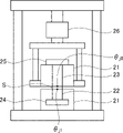
- the thermal resistance value was measured by the method shown below using a thermal resistance measuring device as shown in FIG. Specifically, for each sample, a test piece S having a size of 30 mm ⁇ 30 mm was prepared for this test. Then, each test piece S is attached onto a copper block 22 having a measurement surface of 25.4 mm ⁇ 25.4 mm and whose side surface is covered with a heat insulating material 21, sandwiched between the upper copper blocks 23, and pressed by a load cell 26 at a pressure of 40 psi (. A load of 0.276 MPa) was applied. Here, the lower copper block 22 is in contact with the heater 24.
- the upper copper block 23 is covered with the heat insulating material 21 and connected to the heat sink 25 with a fan.
- the heater 24 is heated with a calorific value of 25 W, and 10 minutes after the temperature becomes substantially steady, the temperature of the upper copper block 23 ( ⁇ j0 ), the temperature of the lower copper block 22 ( ⁇ j1 ), and the heater.
- the calorific value (Q) was measured, and the thermal resistance value of each sample was obtained from the following formula (1). The temperature was adjusted so that the temperature of the heat conductive sheet was 80 ° C.
- compression strain The compression strain was measured according to the method described in the specification.
- the test piece used for the measurement had the same shape as the evaluation of the compressibility.
- Example 1 Side-chain crystalline polyalphaolefin (CPAO, melting point (Tm): 42 ° C.) as the hydrocarbon compound (B) and n-decyltrimethoxysilane as the compatible substance (D) are added according to the blending amounts in Table 1.
- the mixture was mixed at 23 ° C. to obtain a mixture in which the hydrocarbon compound (B) was dissolved in the compatible substance (D).
- the silicone main agent 1 alkenyl group-containing organopolysiloxane
- silicone curing agent hydroogen organopolysiloxane
- platinum-based catalyst platinum-based catalyst
- thermally conductive filler (C) aluminum powder (spherical, average particle size 3 ⁇ mm, aspect ratio 1 to 1.5, thermal conductivity 236 W / m ⁇ K) was used as the non-anisotropic filler. .. Further, as an anisotropic filler, scaly graphite powder (average particle size 40 ⁇ m, aspect ratio 15, thermal conductivity 100 W / m ⁇ K), graphitized carbon fiber 1 (average fiber length 77 ⁇ m, aspect ratio 8, thermal conductivity 1200 W). / M ⁇ K) and graphitized carbon fiber 2 (average fiber length 150 ⁇ m, aspect ratio 15, thermal conductivity 900 W / m ⁇ K) were used.
- the volume filling factor of the heat conductive filler (C) in each Example and Comparative Example was 66% by volume.
- the melting point is the temperature of the endothermic peak of the DTA curve measured under the condition of a heating rate of 1 ° C./min by thermal weight differential thermal analysis (TGDTA, "DTG-60” manufactured by Shimadzu Corporation).
- the mixed composition is injected into a mold set to a thickness sufficiently larger than that of the heat conductive sheet, and an 8T magnetic field is applied in the thickness direction to apply the anisotropic filler in the thickness direction.
- the curable silicone composition (A1) was cured by heating at 80 ° C. for 60 minutes to obtain a block-shaped oriented molded body.
- a sheet-shaped molded product in which the anisotropic filler is exposed is obtained, and the sheet-shaped molded product is heat-conducted. It was a sex sheet.
- the obtained heat conductive sheet was evaluated. The evaluation results are shown in Table 1.
- the heat conductive sheet of Example 1 had a high compressibility and a low thermal resistance value, ensured excellent flexibility at high temperatures, and had good heat conductivity. Further, since the heat conductive sheet obtained in Example 1 was a relatively rigid sheet at room temperature lower than the melting point of the hydrocarbon compound (B), the heat conductive sheet was sliced as described above. Was obtained, and it was excellent in handleability. In addition, the compression strain at 80 ° C. is within a predetermined range, and it has shape retention, and since it does not become liquid or the liquid material does not flow out, pump-out does not occur even if it is compressed for a long period of time, and it is reliable. The sex was also good. Furthermore, no bubbles were observed on the surface of the heat conductive sheet, and the appearance was good.
- Examples 2 to 7 The same procedure as in Example 1 was carried out except that the blending amount of each component was changed to the amount shown in Table 1.
- Table 1 shows the evaluation results of the heat conductive sheets obtained in Examples 2 to 7. As shown in Table 1, the heat conductive sheets of Examples 2 to 7 had a high compressibility and a low thermal resistance value, ensured excellent flexibility at high temperatures, and had good heat conductivity. .. Further, since the heat conductive sheets obtained in Examples 2 to 7 were relatively rigid sheets at room temperature lower than the melting point of the hydrocarbon compound (B), heat conduction by slicing as described above. A sex sheet could be obtained, and it was excellent in handleability. In addition, the compression strain at 80 ° C.
- Example 8 The procedure was carried out in the same manner as in Example 1 except that liquid paraffin (melting point: ⁇ 9 ° C.) was used as the hydrocarbon compound (B).
- Table 1 shows the evaluation results of the obtained heat conductive sheet.
- the heat conductive sheet of Example 8 had a high compressibility and a low thermal resistance value, ensured excellent flexibility at high temperatures, and had good heat conductivity.
- the heat conductive sheet obtained in Example 8 was slightly flexible at both room temperature and 80 ° C., but had shape retention. Therefore, the handleability at room temperature was slightly deteriorated, and although it was difficult to slice, a heat conductive sheet could be obtained.
- pump-out did not occur even when compressed for a long period of time, and the reliability was good. Furthermore, no bubbles were observed on the surface of the heat conductive sheet, and the appearance was good.
- Example 9 The same procedure as in Example 1 was carried out except that “Vaseline (white)” (melting point: 33 ° C.) manufactured by Wako Pure Chemical Industries, Ltd. was used as the hydrocarbon compound (B).
- Table 1 shows the evaluation results of the obtained heat conductive sheet. As shown in Table 1, the heat conductive sheet of Example 9 had a high compressibility and a low thermal resistance value, ensured excellent flexibility at high temperatures, and had good heat conductivity. Further, since the heat conductive sheet obtained in Example 9 was a relatively rigid sheet at room temperature lower than the melting point of the hydrocarbon compound (B), the heat conductive sheet was sliced as described above. Was obtained, and it was excellent in handleability. In addition, the compression strain at 80 ° C.
- Example 10 This was carried out in the same manner as in Example 1 except that dimethyldimethoxysilane was used as the compatible substance (D).
- the hydrocarbon compound (B) tended to be difficult to dissolve in the compatible substance (D), and it took time to dissolve, but a heat conductive sheet could be obtained without any problem.
- Table 1 shows the evaluation results of the obtained heat conductive sheet. As shown in Table 1, the heat conductive sheet of Example 10 had a high compressibility and a low thermal resistance value, ensured excellent flexibility at high temperatures, and had good heat conductivity. Further, since the heat conductive sheet obtained in Example 10 was a relatively rigid sheet at room temperature lower than the melting point of the hydrocarbon compound (B), the heat conductive sheet was sliced as described above.
- the compression strain at 80 ° C. is within a predetermined range, and it has shape retention, and since it does not become liquid or the liquid material does not flow out, pump-out does not occur even if it is compressed for a long period of time, and it is reliable.
- the sex was also good. Furthermore, no bubbles were observed on the surface of the heat conductive sheet, and the appearance was good.
- Example 11 This was carried out in the same manner as in Example 1 except that toluene was used as the compatible substance (D).
- Table 1 shows the evaluation results of the obtained heat conductive sheet.
- the heat conductive sheet of Example 11 had a high compressibility and a low thermal resistance value, ensured excellent flexibility at high temperatures, and had good heat conductivity.
- the heat conductive sheet obtained in Example 11 has bubbles on the surface of the heat conductive sheet and is inferior in appearance to that of Example 1, but at room temperature lower than the melting point of the hydrocarbon compound (B). Since it was a relatively rigid sheet, a heat conductive sheet could be obtained by slicing as described above, and it was excellent in handleability.
- the compression strain at 80 ° C. is within a predetermined range, and it has shape retention, and since it does not become liquid or the liquid material does not flow out, pump-out does not occur even if it is compressed for a long period of time, and it is reliable. The sex was also good.
- Example 12 This was carried out in the same manner as in Example 1 except that n-octyltriethoxysilane was used as the compatible substance (D).
- Table 1 shows the evaluation results of the obtained heat conductive sheet. As shown in Table 1, the heat conductive sheet of Example 12 had a high compressibility and a low thermal resistance value, ensured excellent flexibility at high temperatures, and had good heat conductivity. Further, since the heat conductive sheet obtained in Example 12 was a relatively rigid sheet at room temperature lower than the melting point of the hydrocarbon compound (B), the heat conductive sheet was sliced as described above. Was obtained, and it was excellent in handleability. In addition, the compression strain at 80 ° C.
- Example 13 The same procedure as in Example 1 was carried out except that the blending amount of each component was changed to the amount shown in Table 1.
- Table 1 shows the evaluation results of the heat conductive sheet obtained in Example 13. As shown in Table 1, the heat conductive sheet of Example 13 had a high compressibility and a low thermal resistance value, ensured excellent flexibility at high temperatures, and had good heat conductivity. Further, since the heat conductive sheet obtained in Example 13 was a relatively rigid sheet at room temperature lower than the melting point of the hydrocarbon compound (B), the heat conductive sheet was sliced as described above. Was obtained, and it was excellent in handleability. In addition, the compression strain at 80 ° C.
- Example 1 The same procedure as in Example 1 was carried out except that a heat conductive sheet was prepared from a mixed composition obtained by mixing each component according to the formulation shown in Table 1 without using the hydrocarbon compound (B). Table 1 shows the evaluation results of the heat conductive sheet obtained in Comparative Example 1. As shown in Table 1, the heat conductive sheet of Comparative Example 1 had a low compressibility at high temperature and did not have a certain degree of flexibility. Therefore, the followability to the heating element and the radiator is insufficient, and the thermal resistance value becomes high.
- Example 2 The same procedure as in Example 1 was carried out except that the mixed composition obtained by mixing each component according to the formulation shown in Table 1 was used without using the compatible substance (D), but the hydrocarbon compound (B) was used. Was not dispersed in the curable silicone composition (A1), and a block-shaped oriented molded product could not be obtained.
- Example 3 The same procedure as in Example 1 was carried out except that sorbitan trioleate was used instead of the compatible substance (D) and a mixed composition obtained by mixing each component according to the formulation shown in Table 1 was used, but hydrocarbons were used.
- the hydrogen-based compound (B) did not disperse in the curable silicone composition (A1), and a block-shaped oriented molded product could not be obtained.
- the hydrocarbon compound (B) could be dispersed in the silicone matrix (A) by using the compatible substance (D). Therefore, the heat conductive sheet of each embodiment has shape retention and flexibility at high temperature, has good followability to heating elements and heat radiating elements during use, and is easily compressed. In the state, the thermal resistance became low, and the reliability and handleability became good.
- the heat conductive sheet of Comparative Example 1 does not contain the hydrocarbon compound (B) in the binder component, the flexibility at high temperature is insufficient, and the followability and compressibility at the time of use are low. As a result, the thermal resistance also increased. Further, in Comparative Examples 2 and 3, since the compatible substance (D) was not used, the hydrocarbon compound (B) could not be dispersed in the silicone matrix (A), and the heat conductive sheet could not be produced. rice field.
Landscapes
- Chemical & Material Sciences (AREA)
- Chemical Kinetics & Catalysis (AREA)
- Organic Chemistry (AREA)
- Engineering & Computer Science (AREA)
- Polymers & Plastics (AREA)
- Health & Medical Sciences (AREA)
- Medicinal Chemistry (AREA)
- Materials Engineering (AREA)
- Manufacturing & Machinery (AREA)
- Physics & Mathematics (AREA)
- Thermal Sciences (AREA)
- Combustion & Propulsion (AREA)
- Microelectronics & Electronic Packaging (AREA)
- Cooling Or The Like Of Semiconductors Or Solid State Devices (AREA)
- Compositions Of Macromolecular Compounds (AREA)
- Ceramic Engineering (AREA)
Priority Applications (5)
| Application Number | Priority Date | Filing Date | Title |
|---|---|---|---|
| KR1020237005340A KR20230077716A (ko) | 2020-09-30 | 2021-07-21 | 열전도성 시트, 그 장착 방법 및 제조 방법 |
| CN202180055778.0A CN116075547B (zh) | 2020-09-30 | 2021-07-21 | 导热性片、其安装方法及制造方法 |
| JP2022553493A JPWO2022070568A1 (cg-RX-API-DMAC7.html) | 2020-09-30 | 2021-07-21 | |
| US18/021,226 US20230323181A1 (en) | 2020-09-30 | 2021-07-21 | Heat-conductive sheet, method for attaching same and method for producing same |
| EP21874872.1A EP4225001A4 (en) | 2020-09-30 | 2021-07-21 | HEAT-CONDUCTING FILM, METHOD FOR ATTACHING THE SAME AND METHOD FOR PRODUCING THE SAME |
Applications Claiming Priority (2)
| Application Number | Priority Date | Filing Date | Title |
|---|---|---|---|
| JP2020-165565 | 2020-09-30 | ||
| JP2020165565 | 2020-09-30 |
Publications (1)
| Publication Number | Publication Date |
|---|---|
| WO2022070568A1 true WO2022070568A1 (ja) | 2022-04-07 |
Family
ID=80949857
Family Applications (1)
| Application Number | Title | Priority Date | Filing Date |
|---|---|---|---|
| PCT/JP2021/027302 Ceased WO2022070568A1 (ja) | 2020-09-30 | 2021-07-21 | 熱伝導性シート、その装着方法及び製造方法 |
Country Status (7)
| Country | Link |
|---|---|
| US (1) | US20230323181A1 (cg-RX-API-DMAC7.html) |
| EP (1) | EP4225001A4 (cg-RX-API-DMAC7.html) |
| JP (1) | JPWO2022070568A1 (cg-RX-API-DMAC7.html) |
| KR (1) | KR20230077716A (cg-RX-API-DMAC7.html) |
| CN (1) | CN116075547B (cg-RX-API-DMAC7.html) |
| TW (1) | TW202216881A (cg-RX-API-DMAC7.html) |
| WO (1) | WO2022070568A1 (cg-RX-API-DMAC7.html) |
Cited By (2)
| Publication number | Priority date | Publication date | Assignee | Title |
|---|---|---|---|---|
| JPWO2024225395A1 (cg-RX-API-DMAC7.html) * | 2023-04-28 | 2024-10-31 | ||
| CN121759172A (zh) * | 2026-03-03 | 2026-03-31 | 山西沃锦新材料股份有限公司 | 一种低熔点熔盐储能材料及其制备方法 |
Families Citing this family (3)
| Publication number | Priority date | Publication date | Assignee | Title |
|---|---|---|---|---|
| EP4050068B1 (en) * | 2019-10-24 | 2025-01-29 | Shin-Etsu Chemical Co., Ltd. | Thermally conductive silicone composition and production method therefor |
| CN116622239A (zh) * | 2023-06-13 | 2023-08-22 | 深圳先进电子材料国际创新研究院 | 一种相变热界面材料及其制备方法 |
| US20260209590A1 (en) * | 2025-01-22 | 2026-07-23 | Solstice Advanced Materials Us, Inc. | Phase change thermal interface material with high thermal conduction coefficient and pump-out resistance |
Citations (3)
| Publication number | Priority date | Publication date | Assignee | Title |
|---|---|---|---|---|
| JP2010185052A (ja) * | 2009-02-13 | 2010-08-26 | Idemitsu Kosan Co Ltd | 熱硬化性樹脂組成物及びその成型品 |
| JP2013127035A (ja) * | 2011-12-19 | 2013-06-27 | Two-One:Kk | 電気絶縁性・難燃性・機械的性質・柔軟性に優れ、回路接点不良を生じない熱伝導性ゴム組成物及び該ゴム組成物からなる成形物、シート及びその製造方法。 |
| WO2020039560A1 (ja) * | 2018-08-23 | 2020-02-27 | 日立化成株式会社 | 半導体デバイスの製造方法、熱伝導シート、及び熱伝導シートの製造方法 |
Family Cites Families (14)
| Publication number | Priority date | Publication date | Assignee | Title |
|---|---|---|---|---|
| AU723258B2 (en) * | 1996-04-29 | 2000-08-24 | Parker-Hannifin Corporation | Conformal thermal interface material for electronic components |
| JP2001291807A (ja) | 2000-04-10 | 2001-10-19 | Three M Innovative Properties Co | 熱伝導性シート |
| JP3712943B2 (ja) | 2001-02-08 | 2005-11-02 | 富士高分子工業株式会社 | 熱軟化放熱シート及びこれを用いた放熱シート |
| US6815486B2 (en) * | 2002-04-12 | 2004-11-09 | Dow Corning Corporation | Thermally conductive phase change materials and methods for their preparation and use |
| JP4149846B2 (ja) | 2003-05-08 | 2008-09-17 | 富士高分子工業株式会社 | 放熱シート |
| JP5166677B2 (ja) * | 2005-03-15 | 2013-03-21 | 東レ・ダウコーニング株式会社 | 硬化性シリコーン組成物および電子部品 |
| WO2008147825A2 (en) * | 2007-05-22 | 2008-12-04 | Honeywell International Inc. | Thermal interconnect and interface materials, methods of production and uses thereof |
| JP5156511B2 (ja) * | 2008-07-11 | 2013-03-06 | ポリマテック株式会社 | 熱伝導性シート複合体及びその製造方法 |
| TWI486387B (zh) * | 2012-07-07 | 2015-06-01 | 迪睿合股份有限公司 | Method for manufacturing thermally conductive sheets |
| US9428680B2 (en) * | 2013-03-14 | 2016-08-30 | Dow Corning Corporation | Conductive silicone materials and uses |
| JP6042307B2 (ja) * | 2013-10-16 | 2016-12-14 | 信越化学工業株式会社 | 硬化性熱伝導性樹脂組成物、該組成物の製造方法、該組成物の硬化物、該硬化物の使用方法、該組成物の硬化物を有する半導体装置、及び該半導体装置の製造方法 |
| JP6436035B2 (ja) * | 2015-09-25 | 2018-12-12 | 信越化学工業株式会社 | 熱軟化性熱伝導性シリコーングリース組成物、熱伝導性被膜の形成方法、放熱構造及びパワーモジュール装置 |
| US11608419B2 (en) * | 2017-01-26 | 2023-03-21 | Shin-Etsu Chemical Co., Ltd. | Thermally conductive sheet |
| CN110770319B (zh) * | 2017-06-27 | 2021-12-07 | 积水保力马科技株式会社 | 导热性片 |
-
2021
- 2021-07-21 JP JP2022553493A patent/JPWO2022070568A1/ja active Pending
- 2021-07-21 CN CN202180055778.0A patent/CN116075547B/zh not_active Expired - Fee Related
- 2021-07-21 WO PCT/JP2021/027302 patent/WO2022070568A1/ja not_active Ceased
- 2021-07-21 US US18/021,226 patent/US20230323181A1/en not_active Abandoned
- 2021-07-21 EP EP21874872.1A patent/EP4225001A4/en not_active Withdrawn
- 2021-07-21 KR KR1020237005340A patent/KR20230077716A/ko not_active Withdrawn
- 2021-07-22 TW TW110126969A patent/TW202216881A/zh unknown
Patent Citations (3)
| Publication number | Priority date | Publication date | Assignee | Title |
|---|---|---|---|---|
| JP2010185052A (ja) * | 2009-02-13 | 2010-08-26 | Idemitsu Kosan Co Ltd | 熱硬化性樹脂組成物及びその成型品 |
| JP2013127035A (ja) * | 2011-12-19 | 2013-06-27 | Two-One:Kk | 電気絶縁性・難燃性・機械的性質・柔軟性に優れ、回路接点不良を生じない熱伝導性ゴム組成物及び該ゴム組成物からなる成形物、シート及びその製造方法。 |
| WO2020039560A1 (ja) * | 2018-08-23 | 2020-02-27 | 日立化成株式会社 | 半導体デバイスの製造方法、熱伝導シート、及び熱伝導シートの製造方法 |
Non-Patent Citations (1)
| Title |
|---|
| See also references of EP4225001A4 * |
Cited By (4)
| Publication number | Priority date | Publication date | Assignee | Title |
|---|---|---|---|---|
| JPWO2024225395A1 (cg-RX-API-DMAC7.html) * | 2023-04-28 | 2024-10-31 | ||
| WO2024225395A1 (ja) * | 2023-04-28 | 2024-10-31 | 積水化学工業株式会社 | 熱伝導性部材、熱伝導性組成物、構造体、及び構造体のリワーク方法 |
| JP7727274B2 (ja) | 2023-04-28 | 2025-08-21 | 積水化学工業株式会社 | 熱伝導性部材、熱伝導性組成物、構造体、及び構造体のリワーク方法 |
| CN121759172A (zh) * | 2026-03-03 | 2026-03-31 | 山西沃锦新材料股份有限公司 | 一种低熔点熔盐储能材料及其制备方法 |
Also Published As
| Publication number | Publication date |
|---|---|
| EP4225001A4 (en) | 2024-11-13 |
| CN116075547A (zh) | 2023-05-05 |
| TW202216881A (zh) | 2022-05-01 |
| JPWO2022070568A1 (cg-RX-API-DMAC7.html) | 2022-04-07 |
| KR20230077716A (ko) | 2023-06-01 |
| US20230323181A1 (en) | 2023-10-12 |
| CN116075547B (zh) | 2024-04-09 |
| EP4225001A1 (en) | 2023-08-09 |
Similar Documents
| Publication | Publication Date | Title |
|---|---|---|
| CN114555714B (zh) | 导热片及其制造方法 | |
| CN111699090B (zh) | 导热性片 | |
| CN116075547B (zh) | 导热性片、其安装方法及制造方法 | |
| CN112655085B (zh) | 导热性片 | |
| JP2025074285A (ja) | 熱伝導性シート及びその製造方法 | |
| JP2020074431A (ja) | 熱伝導性シート | |
| WO2022163192A1 (ja) | 熱伝導性シート、その装着方法及び製造方法 | |
| WO2022210419A1 (ja) | 熱伝導性シートの製造方法 | |
| JP7089322B1 (ja) | 熱伝導性シート、その装着方法及び製造方法 | |
| JP7424713B1 (ja) | 熱伝導性シート | |
| JP7424714B1 (ja) | 熱伝導性シート、その装着方法及び製造方法 | |
| WO2023080234A1 (ja) | 熱伝導性シート | |
| WO2024225391A1 (ja) | 熱伝導性シート |
Legal Events
| Date | Code | Title | Description |
|---|---|---|---|
| 121 | Ep: the epo has been informed by wipo that ep was designated in this application |
Ref document number: 21874872 Country of ref document: EP Kind code of ref document: A1 |
|
| ENP | Entry into the national phase |
Ref document number: 2022553493 Country of ref document: JP Kind code of ref document: A |
|
| NENP | Non-entry into the national phase |
Ref country code: DE |
|
| ENP | Entry into the national phase |
Ref document number: 2021874872 Country of ref document: EP Effective date: 20230502 |
|
| WWW | Wipo information: withdrawn in national office |
Ref document number: 2021874872 Country of ref document: EP |