WO2022070553A1 - 建設機械の作業制御方法、作業制御システム及び作業制御装置 - Google Patents
建設機械の作業制御方法、作業制御システム及び作業制御装置 Download PDFInfo
- Publication number
- WO2022070553A1 WO2022070553A1 PCT/JP2021/026609 JP2021026609W WO2022070553A1 WO 2022070553 A1 WO2022070553 A1 WO 2022070553A1 JP 2021026609 W JP2021026609 W JP 2021026609W WO 2022070553 A1 WO2022070553 A1 WO 2022070553A1
- Authority
- WO
- WIPO (PCT)
- Prior art keywords
- control
- smoothing
- rate
- work
- gain
- Prior art date
- Legal status (The legal status is an assumption and is not a legal conclusion. Google has not performed a legal analysis and makes no representation as to the accuracy of the status listed.)
- Ceased
Links
Images




Classifications
-
- G—PHYSICS
- G05—CONTROLLING; REGULATING
- G05B—CONTROL OR REGULATING SYSTEMS IN GENERAL; FUNCTIONAL ELEMENTS OF SUCH SYSTEMS; MONITORING OR TESTING ARRANGEMENTS FOR SUCH SYSTEMS OR ELEMENTS
- G05B13/00—Adaptive control systems, i.e. systems automatically adjusting themselves to have a performance which is optimum according to some preassigned criterion
- G05B13/02—Adaptive control systems, i.e. systems automatically adjusting themselves to have a performance which is optimum according to some preassigned criterion electric
- G05B13/0205—Adaptive control systems, i.e. systems automatically adjusting themselves to have a performance which is optimum according to some preassigned criterion electric not using a model or a simulator of the controlled system
- G05B13/021—Adaptive control systems, i.e. systems automatically adjusting themselves to have a performance which is optimum according to some preassigned criterion electric not using a model or a simulator of the controlled system in which a variable is automatically adjusted to optimise the performance
-
- E—FIXED CONSTRUCTIONS
- E02—HYDRAULIC ENGINEERING; FOUNDATIONS; SOIL SHIFTING
- E02F—DREDGING; SOIL-SHIFTING
- E02F9/00—Component parts of dredgers or soil-shifting machines, not restricted to one of the kinds covered by groups E02F3/00 - E02F7/00
- E02F9/20—Drives; Control devices
-
- E—FIXED CONSTRUCTIONS
- E02—HYDRAULIC ENGINEERING; FOUNDATIONS; SOIL SHIFTING
- E02F—DREDGING; SOIL-SHIFTING
- E02F9/00—Component parts of dredgers or soil-shifting machines, not restricted to one of the kinds covered by groups E02F3/00 - E02F7/00
- E02F9/20—Drives; Control devices
- E02F9/2025—Particular purposes of control systems not otherwise provided for
-
- G—PHYSICS
- G05—CONTROLLING; REGULATING
- G05B—CONTROL OR REGULATING SYSTEMS IN GENERAL; FUNCTIONAL ELEMENTS OF SUCH SYSTEMS; MONITORING OR TESTING ARRANGEMENTS FOR SUCH SYSTEMS OR ELEMENTS
- G05B11/00—Automatic controllers
- G05B11/01—Automatic controllers electric
- G05B11/36—Automatic controllers electric with provision for obtaining particular characteristics, e.g. proportional, integral, differential
-
- G—PHYSICS
- G05—CONTROLLING; REGULATING
- G05B—CONTROL OR REGULATING SYSTEMS IN GENERAL; FUNCTIONAL ELEMENTS OF SUCH SYSTEMS; MONITORING OR TESTING ARRANGEMENTS FOR SUCH SYSTEMS OR ELEMENTS
- G05B13/00—Adaptive control systems, i.e. systems automatically adjusting themselves to have a performance which is optimum according to some preassigned criterion
- G05B13/02—Adaptive control systems, i.e. systems automatically adjusting themselves to have a performance which is optimum according to some preassigned criterion electric
-
- E—FIXED CONSTRUCTIONS
- E02—HYDRAULIC ENGINEERING; FOUNDATIONS; SOIL SHIFTING
- E02F—DREDGING; SOIL-SHIFTING
- E02F9/00—Component parts of dredgers or soil-shifting machines, not restricted to one of the kinds covered by groups E02F3/00 - E02F7/00
- E02F9/20—Drives; Control devices
- E02F9/2025—Particular purposes of control systems not otherwise provided for
- E02F9/205—Remotely operated machines, e.g. unmanned vehicles
Definitions
- the present invention relates to a work control method, a work control system and a work control device of a construction machine, and particularly to a work control method, a work control system and a work control device of a construction machine that controls the attitude of the construction machine by numerical control using a computer.
- Patent Documents 1 and 2 disclose an example of a technique for suppressing the occurrence of overshoot.
- the motor control device described in Patent Document 1 includes a response diagnosis unit that inputs a position deviation to diagnose vibration during positioning time, overshoot, and servo lock, and a position control unit and a speed control unit based on the results. A number of cycles of adjusting the torque filter unit, current control unit, speed signal creation unit, speed feed forward compensation unit, torque feed forward compensation unit, and driving the motor again based on the adjusted gain. It is repeated a number of times to automatically tune the optimum control gain, and is provided with a tuning end determination unit that determines that tuning is completed when a predetermined evaluation function becomes smaller than a preset value.
- the process control device described in Patent Document 2 is a process control device that feedback-controls a process control amount to a target value and at least performs proportional / integral control, and the target value generated by a change in the target value or application of a disturbance.
- the control deviation between the control amount and the control amount is observed in a waveform, and the control deviation is time-integrated every half cycle to calculate the area value, and the area value is used by a predetermined adjustment rule. It is provided with a correction means for adjusting control parameters.
- One aspect of the work control method of the construction machine of the present invention is a control parameter adjustment process for adjusting the control gain for each control section which is a control unit section, and feedback control for controlling the posture of the construction machine by using the control gain.
- the feedback control process for calculating the input value is performed, and the overshoot calculation process for calculating the overshoot amount of the attitude detection value with respect to the target position in the pre-control section and the next based on the overshoot amount.
- the control is based on the control gain adjustment rate for calculating the control gain adjustment rate, which is the control gain adjustment rate in the control section, and the smoothed post-smoothing reduction rate and the control gain adjustment rate calculated in the pre-control section.
- the adjustment rate smoothing process for calculating the adjustment rate after smoothing by smoothing the gain adjustment rate and the control gain calculation process for calculating the control gain of the next control section from the adjustment rate after smoothing are performed.
- One aspect of the work control system for a construction machine of the present invention is a control parameter adjusting unit that adjusts a control gain for each control section, which is a control unit section, and feedback control that controls the posture of the construction machine using the control gain. It has a feedback control unit that calculates an input value and a construction machine control unit that controls the attitude of the construction machine based on the feedback control input value, and the control parameter adjustment unit has an attitude with respect to a target position in the front control section.
- the overshoot calculation unit that calculates the overshoot amount of the detected value
- the control gain adjustment rate calculation unit that calculates the control gain adjustment rate of the control gain in the next control section based on the overshoot amount, and the previous control section.
- the control gain decrement rate is smoothed and the post-smoothing adjustment rate is calculated. It has a control gain calculation unit that calculates the control gain of the next control section from the rate.
- One aspect of the work control device for a construction machine of the present invention is a control parameter adjusting unit that adjusts a control gain for each control section, which is a control unit section, and a feedback control that controls the posture of the construction machine using the control gain. It has a feedback control unit that calculates an input value, and the control parameter adjustment unit has an overshoot calculation unit that calculates an overshoot amount of an attitude detection value with respect to a target position in a pre-control section, and an overshoot calculation unit based on the overshoot amount.
- the control gain adjustment rate which is the control gain adjustment rate of the next control section, is calculated based on the adjustment rate calculation unit, the smoothed post-smoothing reduction rate calculated in the previous control section, and the control gain adjustment rate. It has an adjustment rate smoothing processing unit that calculates the adjustment rate after smoothing by smoothing the control gain adjustment rate, and a control gain calculation unit that calculates the control gain of the next control section from the adjustment rate after smoothing.
- FIG. It is a schematic diagram of the construction machine to be controlled of the work control system which concerns on Embodiment 1.
- FIG. It is a schematic block diagram of the work control system which concerns on Embodiment 1.
- FIG. It is a detailed block diagram of the work control system which concerns on Embodiment 1.
- FIG. It is a block diagram of the addition / subtraction rate smoothing processing part which concerns on Embodiment 1.
- FIG. It is a flowchart explaining the overshoot calculation process which concerns on Embodiment 1. It is a timing chart explaining the size of the overshoot targeted in the overshoot calculation process. It is a flowchart explaining the addition / subtraction rate calculation process which concerns on Embodiment 1.
- each element described in the drawing as a functional block that performs various processing can be configured by a CPU (Central Processing Unit), a memory, and other circuits in terms of hardware, and in terms of software, memory. It is realized by the program loaded in. Therefore, it is understood by those skilled in the art that these functional blocks can be realized in various forms by hardware only, software only, or a combination thereof, and the present invention is not limited to any of them.
- the same elements are designated by the same reference numerals, and duplicate explanations are omitted as necessary.
- Non-temporary computer-readable media include various types of tangible recording media.
- Examples of non-temporary computer-readable media include magnetic recording media (eg, flexible disks, magnetic tapes, hard disk drives), magneto-optical recording media (eg, magneto-optical disks), CD-ROMs (ReadOnlyMemory), CD-Rs, Includes CD-R / W, semiconductor memory (eg, mask ROM, PROM (Programmable ROM), EPROM (Erasable PROM), flash ROM, RAM (RandomAccessMemory)).
- the program may also be supplied to the computer by various types of temporary computer-readable media. Examples of temporary computer readable media include electrical, optical, and electromagnetic waves.
- the temporary computer-readable medium can supply the program to the computer via a wired communication path such as an electric wire and an optical fiber, or a wireless communication path.
- Embodiment 1 Hereinafter, embodiments of the present invention will be described with reference to the drawings.
- the work control method, work control system, and work control device of the construction machine described below control the construction machine that drives the joints of the machine by using a cylinder. Therefore, in the following description, a backhoe will be taken as an example as a construction machine. Further, in the following description, a work control system in which processing blocks for performing work control processing are distributed and arranged at a plurality of locations through a network will be described, but work in which the processing blocks included in the work control system are used as one device. It may be a control device. Further, the control content performed in the work control system is referred to as a work control method.
- the work control system described below can be applied to a machine having an operation lever that can be operated by an operator as a construction machine, or an electromagnetic proportional valve or the like is used by an electric signal without using the operation lever. It can also be applied to machines that directly control the drive mechanism.
- FIG. 1 shows a schematic diagram of a construction machine to be controlled by the work control system 1 according to the first embodiment.
- the construction machine 10 shown in FIG. 1 is a backhoe.
- the construction machine 10 has a crawler 11, a swivel table 12, a cockpit 13, a boom 14, an arm 15, and a bucket 16.
- the crawler 11 is an endless track for moving the construction machine 10.
- the swivel base 12 swivels the chassis on which the cockpit 13, the boom 14, and the like are mounted.
- the cockpit 13 is an operation room in which an operation lever or the like for operating the posture of the construction machine 10 is arranged.
- the construction machine drive processing unit 17 is arranged in the construction machine 10.
- the boom 14, the arm 15, and the bucket 16 each correspond to a movable portion and are operated by a hydraulic cylinder.
- This hydraulic cylinder expands and contracts due to the action of the construction machine drive processing unit 17.
- the part corresponding to the movable part includes, for example, a part driven by a motor.
- the construction machine drive processing unit 17 may, for example, operate an actuator that displaces the operation lever with respect to an operation lever that can be operated by the operator, or may operate an electromagnetic proportional valve or the like by an electric signal. can.
- a movable part such as a boom 14 of the construction machine 10 is moved by giving a feedback control input value to the construction machine drive processing unit 17 of the construction machine 10. Then, in the work control system 1 according to the first embodiment, the feedback control is performed while adjusting the control gain used in the feedback control for each predetermined control section.
- the work control system 1 according to the first embodiment will be described in detail below.
- FIG. 2 shows a schematic block diagram of the work control system according to the first embodiment.
- the construction machine 10 is shown as the one to be controlled by the work control system 1.
- the attitude control device 20 is provided with a construction machine control unit 21 and an attitude detection unit 22.
- the work control device 30 is provided with a control parameter adjusting unit 31 and a feedback control unit 32. Then, the construction machine 10 is operated by using the attitude control device 20 and the work control device 30.
- FIG. 1 shows a schematic block diagram of the work control system according to the first embodiment.
- the construction machine 10 is shown as the one to be controlled by the work control system 1.
- the attitude control device 20 is provided with a construction machine control unit 21 and an attitude detection unit 22.
- the work control device 30 is provided with a control parameter adjusting unit 31 and a feedback control unit 32. Then, the construction machine 10 is operated by using the attitude control device 20 and the work control device 30.
- FIG. 1 shows a schematic block diagram of the work control system according to the first embodiment.
- the attitude control device 20 and the work control device 30 can be used as one device, and the construction machine 10 and the attitude control device 20 can be connected by communication.
- the attitude control device 20 may be provided so as to be integrated with the construction machine 10, and the attitude control device 20 and the work control device 30 may be connected by communication.
- the construction machine 10 is a control target by the work control device 30, and the attitude control device 20 is also regarded as an interface for the work control device 30 to specifically operate the construction machine 10. In that case, the work control device 30 Can be considered as the main part of the work control system 1.
- the attitude control device 20 has a construction machine control unit 21 and an attitude detection unit 22.
- the construction machine control unit 21 operates the movable part of the construction machine 10 by giving the fordback control input value calculated by the feedback control unit 32 to the construction machine drive processing unit 17.
- the posture detection unit 22 acquires the joint angle of each movable portion from a sensor provided on a movable portion such as an arm of the construction machine 10 and outputs it as a posture detection value indicating the posture of the construction machine 10.
- the work control device 30 has a control parameter adjustment unit 31 and a feedback control unit 32.
- the control parameter adjusting unit 31 adjusts the control gain for each control section which is a control unit interval. Further, the control parameter adjusting unit 31 adjusts the control gain for each control section based on the attitude detection value detected by the attitude detecting unit 22. The details of this control gain adjustment process will be described later.
- the feedback control unit 32 calculates a feedback control input value for controlling the attitude of the construction machine by using the control gain calculated by the control parameter adjustment unit 31 and the attitude detection value acquired from the attitude detection unit 22. The feedback control unit 32 performs this feedback control input value generation process by PID control or the like using the attitude detection value.
- this feedback control input value may be generated for each moving part of the construction machine 10, or may include input values for a plurality of moving parts. Further, the work control system 1 shall calculate the input value using different parameters for each movable part.
- FIG. 3 shows a detailed block diagram of the work control system 1 according to the first embodiment.
- the work control device 30 has a control parameter adjustment unit 31, a feedback control unit 32, and a work instruction unit 33.
- the work instruction unit 33 gives a work instruction indicating the work content to be performed by the construction machine 10 to the control parameter adjustment unit 31 and the feedback control unit 32.
- the control parameter adjusting unit 31 and the feedback control unit 32 will be described in detail below.
- the control parameter adjustment unit 31 has an overshoot calculation unit 311, an adjustment rate calculation unit 312, an adjustment rate smoothing processing unit 313, and a control gain calculation unit 314.
- the overshoot calculation unit 311 calculates the overshoot amount of the attitude detection value with respect to the target position in the pre-control section. This posture detection value is output from the posture detection unit 22.
- the adjustment rate calculation unit 312 calculates the control gain adjustment rate, which is the adjustment rate of the control gain in the next control section, based on the overshoot amount.
- the adjustment rate smoothing processing unit 313 is based on the increase / decrease direction of the control gain adjustment rate determined by the smoothing post-smoothing reduction rate calculated in the pre-control section and the control gain adjustment rate calculated by the adjustment rate calculation unit 312.
- the post-smoothing lapse rate is calculated by smoothing the control gain lapse rate using the switchable smoothing coefficient.
- the control gain calculation unit 314 calculates the control gain of the next control section from the adjustment rate after smoothing.
- the adjustment rate smoothing processing unit 313 includes a smoothing coefficient determining unit 41 and a post-smoothing adjustment rate calculation unit 42.
- the smoothing coefficient determination unit 41 rewrites the smoothing coefficient so that when the control gain adjustment rate is larger than the post-smoothing adjustment rate calculated in the pre-control interval, the smoothing coefficient becomes a smaller value than at other times, and smoothing is performed. Output the coefficient.
- a combination of a large value and a small value is treated as one set as a smoothing coefficient. Further, in the work control system 1 according to the first embodiment, a plurality of sets of smoothing coefficients according to the difference in the controlled target portion or the work instruction content are held in the system in advance.
- the post-smoothing adjustment rate calculation unit 42 has a smoothing coefficient determined by the smoothing coefficient determination unit 41 with respect to the control gain adjustment rate corresponding to the previous control section and the control gain adjustment rate corresponding to the next control section. Is applied to the smoothing process to calculate the post-smoothing addition / subtraction factor.
- the feedback control unit 32 has an error update unit 321 and a control input calculation unit 322.
- the error updating unit 321 calculates an error between the target position included in the work content instruction obtained from the work instruction unit 33 and the posture detection value obtained from the posture detection unit 22.
- the control input calculation unit 322 calculates a feedback control input value for controlling the posture of the construction machine by using the control gain calculated by the control gain calculation unit 314. At this time, the control input calculation unit 322 calculates the feedback control input value so that the error calculated by the error update unit 321 approaches zero.
- FIG. 5 shows a flowchart illustrating the overshoot calculation process according to the first embodiment.
- the overshoot direction is calculated from the difference between the initial position of the control section and the target position (step S1).
- an error with respect to the overshoot direction of the current position and the target position of the controlled target portion grasped from the posture detection value is calculated (step S2).
- the maximum error from the initial time of the control section to the current time is calculated (step S3).
- the processes of steps S2 and S3 are repeated until the target position is switched (step S4).
- the overshoot calculation unit 311 calculates the maximum error detected through steps S2 to S4 as the overshoot amount in the pre-control section (step S5).
- FIG. 6 shows a timing chart for explaining the size of the overshoot targeted in the overshoot calculation process.
- the control section is switched each time the target position is switched. For example, in the example shown in FIG. 6, the period from the time t1 (j) to the time t2 (j) in which ⁇ T (i) is set as the target position is defined as the control section j.
- the overshoot calculation unit 311 sets the position of the controlled target portion at the start time of the control section to ⁇ (t1 (j)) and the target position ⁇ T (i) in the control section j. Judgment is based on the difference between. Further, the overshoot calculation unit 311 calculates an error in the direction determined in step S1 in step S2. Further, the overshoot calculation unit 311 continuously acquires the maximum value of the overshoot in the same direction as the change direction of the target position during the control section.
- the error with respect to the target position ⁇ T (i) is e i (t)
- the error e i (t) is expressed by the equation (1).
- the error e (i) is accumulated every time the maximum value of overshoot occurs.
- the overshoot calculation unit 311 uses the equation (2) to obtain the maximum value a (j) of the error during the control period j (the period from t1 (j) to t2 (j)). Is calculated, and the calculated maximum value is calculated as the overshoot amount a (j).
- FIG. 7 shows a flowchart illustrating the addition / subtraction rate calculation process according to the first embodiment.
- the addition / subtraction rate calculation unit 312 acquires the overshoot amount of the pre-control section calculated by the overshoot calculation unit 311 (step S11).
- the addition / subtraction rate calculation unit 312 acquires the current work content from the work instruction unit 33 (step S12).
- the adjustment rate calculation unit 312 calculates the control gain adjustment rate for the current work content from the overshoot amount in the previous control section (step S13).
- control gain adjustment rate is assumed to be (3), where the overshoot amount is a (j), the weighting coefficient set to an arbitrary size is ⁇ , and the control gain adjustment rate corresponding to the control section j is r (j). ) Can be expressed.
- FIG. 8 shows a flowchart illustrating the smoothing coefficient determination process according to the first embodiment.
- the smoothing coefficient determination unit 41 acquires the control gain adjustment rate calculated by the adjustment rate calculation unit 312 (step S21).
- the smoothing coefficient determination unit 41 acquires the post-smoothing adjustment rate of the pre-control section from the post-smoothing adjustment rate calculation unit 42 (step S22).
- the smoothing coefficient determination unit 41 compares the control gain adjustment rate acquired in step S21 with the smoothing adjustment rate acquired in step S22 (step S23).
- step S23 when the control gain adjustment rate is larger than the adjustment rate after smoothing, the smoothing coefficient determining unit 41 determines that the adjustment rate is increasing, and the smoothing coefficient ⁇ when the increase rate increases. Is a smoothing coefficient when the rate of increase increases, which is used in the calculation of the control gain in the next control section (step S24).
- step S23 when the control gain adjustment rate is equal to or less than the adjustment rate after smoothing, the smoothing coefficient determining unit 41 determines that the adjustment rate is decreasing, and the smoothing coefficient ⁇ when the increase rate decreases. Is a smoothing coefficient when the rate of increase increases, which is used in the calculation of the control gain in the next control section (step S25).
- the smoothing coefficient ⁇ and the smoothing coefficient ⁇ have a relationship of ⁇ ⁇ .
- FIG. 9 shows a flowchart illustrating the smoothing addition / subtraction rate calculation process according to the first embodiment.
- the post-smoothing addition / subtraction rate calculation unit 42 acquires the smoothing coefficient calculated by the smoothing coefficient determination unit 41 (step S31). Further, the smoothed adjustment rate calculation unit 42 acquires the control gain adjustment rate calculated by the adjustment rate calculation unit 312 (step S32). Then, the smoothed adjustment rate calculation unit 42 calculates the smoothing adjustment rate of the next control section using the values acquired in steps S31 and S32 (step S33).
- the smoothing coefficient calculated by the smoothing coefficient determining unit 41 differs depending on the increasing / decreasing direction of the control gain adjustment rate. Therefore, the smoothed adjustment rate calculated in step S33 is calculated by either the equation (4) or the equation (5) depending on the difference in the increase / decrease direction of the control gain adjustment rate. Equation (4) is for when the control gain adjustment rate is in the direction of increasing, and equation (5) is for when the control gain adjustment rate is in the direction of decreasing.
- R (j) is the adjustment rate after smoothing of the control section j, and R (j + 1) is the adjustment rate after smoothing of the control section j + 1 which is the next control section.
- the post-smoothing adjustment rate R (1) in the control section at the start of operation of the construction machine 10 is 1.
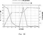
- FIG. 10 shows a graph explaining the relationship between the overshoot amount and the smoothing adjustment rate.
- the control parameter adjusting unit 31 according to the first embodiment is used to repeatedly execute the processing for 10 control sections.
- the horizontal axis shows the number of control sections (number of trials) in which trials are repeated
- the vertical axis on the left side shows the amount of overshoot
- the vertical axis on the right side shows the adjustment rate after smoothing.
- the overshoot amount is shown by a solid line
- the adjustment rate after smoothing is shown by a alternate long and short dash line.
- the smoothing coefficient ⁇ selected in the direction in which the overshoot amount is large and the control gain adjustment rate increases is 0.8, the overshoot amount is small, and the control gain adjustment rate decreases.
- the smoothing coefficient ⁇ selected in is 0.99.
- the amount of overshoot is suppressed to a certain value or less during the trial period in which the number of trials is 3 to 5 times. Therefore, the slip ratio applied to the control gain corresponding to the 4th to 6th trials gradually decreases. As a result, the operating speed of the construction machine 10 is maintained while the overshoot amount is maintained so as to be suppressed to a certain value or less.
- the slip ratio applied to the control gain corresponding to the seventh trial is greatly increased. As a result, the control gain becomes smaller in the direction in which the overshoot amount is suppressed.
- the amount of overshoot is suppressed to a certain value or less during the trial period in which the number of trials is 7 to 10. Therefore, the slipping adjustment rate applied to the control gain corresponding to the 8th to 11th trials (the 11th is not shown) gradually decreases. As a result, the operating speed of the construction machine 10 is maintained while the overshoot amount is maintained so as to be suppressed to a certain value or less.
- the adjustment rate applied to the calculation of the control gain by using the adjustment rate calculation unit 312, the smoothing coefficient determination unit 41, and the smoothed adjustment rate calculation unit 42 is smoothing the above, the overshoot amount is immediately suppressed to a certain value or less, and when the overshoot amount is small, the control gain is adjusted to gradually increase.
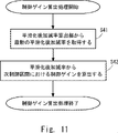
- FIG. 11 shows a flowchart illustrating the control gain calculation process according to the first embodiment.
- the control gain calculation unit 314 first.
- the latest post-smoothing adjustment rate calculated by the smoothing adjustment rate calculation unit 42 is acquired (step S41).
- the control gain calculation unit 314 calculates the control gain in the next control section using the smoothed addition / subtraction rate acquired in step S41 (step S42).
- the control gain calculation process in the control gain calculation unit 314 will be described in more detail.
- the pre-control section in which the maximum value of the overshoot amount is acquired is set to j
- the control section to which the control gain calculated based on the result of the pre-control section j is applied is set to j + 1.
- the control gain corresponding to the next control section j + 1 is K (j + 1)
- the initial value of the control gain is K (1)
- the smoothing adjustment is calculated based on the result of the previous control section j and applied to the next control section j + 1.
- the rate be R (j + 1). Under such conditions, the control gain calculation unit 314 calculates the control gain K (j + 1) to be applied to the next control section j + 1 based on the equation (6).
- the feedback control unit 32 has an error update unit 321 and a control input calculation unit 322. Then, the error update unit 321 calculates the error between the real-time posture detection value and the target position. Then, the control input calculation unit 322 calculates a feedback control input value that brings the error close to zero. Therefore, the process of calculating the feedback control input value in the control input calculation unit 322 will be described.
- FIG. 12 shows a flowchart illustrating the feedback control process according to the first embodiment.
- control input calculation unit 322 first acquires the control gain calculated by the control gain calculation unit 314 (step S51). Next, the control input calculation unit 322 calculates the feedback control input value using the acquired control gain (step S52). That is, the feedback control unit 32 calculates the feedback control input value based on the control gain updated by the control parameter adjustment unit 31.
- the magnitude of the control gain applied to the next control section is adjusted based on the overshoot amount generated in the previous control section for each control section. That is, in the work control system 1 according to the first embodiment, the control gain is adjusted according to the torque of each part or the work content that changes during the operation of the construction machine 10.
- the work contents include extending the arm to the excavation point, inserting the cutting edge of the bucket into the excavation point, excavating, lifting, turning with the excavated earth and sand on it, discharging the earth and sand contained in the bucket, etc.
- smoothing is performed according to the comparison result between the smoothing adjustment rate calculated in the pre-control section and the control gain adjustment rate calculated from the overshoot amount generated in the pre-control section.
- Either the smoothing coefficient ⁇ or the smoothing coefficient ⁇ is selected by the post-adjustment rate calculation unit 42.
- the relationship between the smoothing coefficient ⁇ and the smoothing coefficient ⁇ is set to ⁇ ⁇ .
- the work control system 1 according to the first embodiment increases the sensitivity in the decreasing direction of the control gain and lowers the sensitivity in the increasing direction of the control gain.
- the work control system 1 according to the first embodiment does not unreasonably suppress the operating speed of the construction machine 10 while immediately suppressing the size of the overshoot within a range of a certain value or less. Such control can be performed.
- the combination of smoothing coefficients selected by the smoothing adjustment rate calculation unit 42 is switched according to the part to be controlled or the work content.
- the work control system 1 according to the first embodiment can calculate the optimum control gain according to the content of the work or the required torque.
- Embodiment 2 In the second embodiment, another embodiment of the control section setting method will be described.
- the change of the target position that occurs in one control section is one.
- the target position is switched a plurality of times within one control section. Then, a method of calculating the overshoot amount when such a change of the target position occurs will be described.
- FIG. 13 shows a timing chart for explaining the relationship between the control section and the target position according to the second embodiment.
- the target position is switched four times in the control section j from the time t1 (j) to the time t2 (j).
- the amount of overshoot generated in the four switching of the target positions is defined as a (i) to a (i + 3), respectively.
- the overshoot amounts a (i) to a (i + 3) are calculated according to the equation (1).
- the calculation is performed according to the equation (7) or the equation (8) instead of the equation (2).
- the average value of the overshoot amounts a (i) to a (i + 3) generated during the control period j is used as the overshoot amount a (j) in the control period.
- the maximum value of the overshoot amount a (i) to a (i + 3) generated during the control period j is set as the overshoot amount a (j) in the control period.
- n and k indicate the number of times the target value is switched within one control period.
- the length of the control section can be arbitrarily set, and the adjustment period of the control gain of the work control system 1 according to the first embodiment can be flexibly set.
Landscapes
- Engineering & Computer Science (AREA)
- Physics & Mathematics (AREA)
- Automation & Control Theory (AREA)
- General Physics & Mathematics (AREA)
- Evolutionary Computation (AREA)
- Medical Informatics (AREA)
- Software Systems (AREA)
- Health & Medical Sciences (AREA)
- Computer Vision & Pattern Recognition (AREA)
- Artificial Intelligence (AREA)
- Mining & Mineral Resources (AREA)
- Civil Engineering (AREA)
- General Engineering & Computer Science (AREA)
- Structural Engineering (AREA)
- Operation Control Of Excavators (AREA)
- Feedback Control In General (AREA)
Priority Applications (2)
| Application Number | Priority Date | Filing Date | Title |
|---|---|---|---|
| US18/021,764 US12248283B2 (en) | 2020-09-29 | 2021-07-15 | Work control method, work control system, and work control apparatus of construction machine |
| JP2022553484A JP7405275B2 (ja) | 2020-09-29 | 2021-07-15 | 建設機械の作業制御方法、作業制御システム及び作業制御装置 |
Applications Claiming Priority (2)
| Application Number | Priority Date | Filing Date | Title |
|---|---|---|---|
| JP2020-162900 | 2020-09-29 | ||
| JP2020162900 | 2020-09-29 |
Publications (1)
| Publication Number | Publication Date |
|---|---|
| WO2022070553A1 true WO2022070553A1 (ja) | 2022-04-07 |
Family
ID=80949822
Family Applications (1)
| Application Number | Title | Priority Date | Filing Date |
|---|---|---|---|
| PCT/JP2021/026609 Ceased WO2022070553A1 (ja) | 2020-09-29 | 2021-07-15 | 建設機械の作業制御方法、作業制御システム及び作業制御装置 |
Country Status (3)
| Country | Link |
|---|---|
| US (1) | US12248283B2 (https=) |
| JP (1) | JP7405275B2 (https=) |
| WO (1) | WO2022070553A1 (https=) |
Cited By (1)
| Publication number | Priority date | Publication date | Assignee | Title |
|---|---|---|---|---|
| JP2024094058A (ja) * | 2022-12-27 | 2024-07-09 | 住友重機械工業株式会社 | ショベル |
Families Citing this family (1)
| Publication number | Priority date | Publication date | Assignee | Title |
|---|---|---|---|---|
| US20230250613A1 (en) * | 2022-02-10 | 2023-08-10 | Zoomlion Heavy Industry Na, Inc. | Remote Wireless Electric Cab |
Citations (5)
| Publication number | Priority date | Publication date | Assignee | Title |
|---|---|---|---|---|
| JPH02245902A (ja) * | 1989-03-20 | 1990-10-01 | Hitachi Ltd | プロセス制御装置 |
| JPH0475113A (ja) * | 1990-07-17 | 1992-03-10 | Sankyo Seiki Mfg Co Ltd | 制御装置 |
| JP2003061377A (ja) * | 2001-08-17 | 2003-02-28 | Yaskawa Electric Corp | オートチューニング機能を備えたモータ制御装置 |
| JP2011006862A (ja) * | 2009-06-23 | 2011-01-13 | Sumitomo (Shi) Construction Machinery Co Ltd | 旋回駆動制御装置及びこれを含む建設機械 |
| US20200024828A1 (en) * | 2018-07-23 | 2020-01-23 | Massachusetts Institute Of Technology | Automated control for excavators |
Family Cites Families (2)
| Publication number | Priority date | Publication date | Assignee | Title |
|---|---|---|---|---|
| CN1077187C (zh) * | 1996-12-12 | 2002-01-02 | 新卡特彼勒三菱株式会社 | 用于建工机械的控制装置 |
| JP5219956B2 (ja) * | 2009-07-23 | 2013-06-26 | 本田技研工業株式会社 | 移動体の制御装置 |
-
2021
- 2021-07-15 US US18/021,764 patent/US12248283B2/en active Active
- 2021-07-15 WO PCT/JP2021/026609 patent/WO2022070553A1/ja not_active Ceased
- 2021-07-15 JP JP2022553484A patent/JP7405275B2/ja active Active
Patent Citations (5)
| Publication number | Priority date | Publication date | Assignee | Title |
|---|---|---|---|---|
| JPH02245902A (ja) * | 1989-03-20 | 1990-10-01 | Hitachi Ltd | プロセス制御装置 |
| JPH0475113A (ja) * | 1990-07-17 | 1992-03-10 | Sankyo Seiki Mfg Co Ltd | 制御装置 |
| JP2003061377A (ja) * | 2001-08-17 | 2003-02-28 | Yaskawa Electric Corp | オートチューニング機能を備えたモータ制御装置 |
| JP2011006862A (ja) * | 2009-06-23 | 2011-01-13 | Sumitomo (Shi) Construction Machinery Co Ltd | 旋回駆動制御装置及びこれを含む建設機械 |
| US20200024828A1 (en) * | 2018-07-23 | 2020-01-23 | Massachusetts Institute Of Technology | Automated control for excavators |
Cited By (1)
| Publication number | Priority date | Publication date | Assignee | Title |
|---|---|---|---|---|
| JP2024094058A (ja) * | 2022-12-27 | 2024-07-09 | 住友重機械工業株式会社 | ショベル |
Also Published As
| Publication number | Publication date |
|---|---|
| US20240027972A1 (en) | 2024-01-25 |
| JPWO2022070553A1 (https=) | 2022-04-07 |
| JP7405275B2 (ja) | 2023-12-26 |
| US12248283B2 (en) | 2025-03-11 |
Similar Documents
| Publication | Publication Date | Title |
|---|---|---|
| EP3392511B1 (en) | Construction machinery | |
| JP3545006B2 (ja) | 2自由度制御装置及び電動機のサーボ制御装置 | |
| KR19990082460A (ko) | 건설 기계의 제어 장치 | |
| JP7146530B2 (ja) | 建設機械 | |
| JPH093959A (ja) | 複数タンデム連結部材を有する油圧操作建設機械の制御 | |
| WO2022070553A1 (ja) | 建設機械の作業制御方法、作業制御システム及び作業制御装置 | |
| JP2018048503A (ja) | 建設機械の制御装置 | |
| US10870968B2 (en) | Work vehicle control system providing coordinated control of actuators | |
| CN110941242A (zh) | 电动机控制装置 | |
| KR20210151812A (ko) | 정수압 작업 도구 및 그 제어 방법 | |
| JP7546123B2 (ja) | バルブシステム | |
| JP6734240B2 (ja) | 油圧作業機械 | |
| WO2020194620A1 (ja) | 作業機械 | |
| JP7609168B2 (ja) | 作業制御方法、作業制御システム及び目標点設定装置 | |
| JP7599347B2 (ja) | 油圧式作業機械 | |
| JP2015148928A (ja) | 建設機械 | |
| JP6814440B2 (ja) | 作業機械 | |
| JP4752298B2 (ja) | モータ制御装置およびその制御方法 | |
| JP2000303492A (ja) | 建設機械のフロント制御装置 | |
| US20240044108A1 (en) | Work control method of construction machine, work control system, and work control apparatus | |
| JP7805796B2 (ja) | 建設機械の制御装置およびこれを備えた建設機械 | |
| KR20030008572A (ko) | 굴삭기의 자동 작업을 수행하기 위한 유압 제어 장치 및방법 | |
| JP7815723B2 (ja) | 制御パラメータ設定方法、設定装置及びプログラム | |
| CN115800866B (zh) | 伺服放大器的自动调谐方法及马达控制装置 | |
| WO2022064823A1 (ja) | 作業制御方法、作業制御システム、作業制御装置及び作業制御プログラムが記録された非一時的なコンピュータ可読媒体 |
Legal Events
| Date | Code | Title | Description |
|---|---|---|---|
| 121 | Ep: the epo has been informed by wipo that ep was designated in this application |
Ref document number: 21874857 Country of ref document: EP Kind code of ref document: A1 |
|
| WWE | Wipo information: entry into national phase |
Ref document number: 18021764 Country of ref document: US |
|
| ENP | Entry into the national phase |
Ref document number: 2022553484 Country of ref document: JP Kind code of ref document: A |
|
| NENP | Non-entry into the national phase |
Ref country code: DE |
|
| 122 | Ep: pct application non-entry in european phase |
Ref document number: 21874857 Country of ref document: EP Kind code of ref document: A1 |
|
| WWG | Wipo information: grant in national office |
Ref document number: 18021764 Country of ref document: US |