WO2022064750A1 - 電動機制御装置および車両、電動機制御方法 - Google Patents
電動機制御装置および車両、電動機制御方法 Download PDFInfo
- Publication number
- WO2022064750A1 WO2022064750A1 PCT/JP2021/016036 JP2021016036W WO2022064750A1 WO 2022064750 A1 WO2022064750 A1 WO 2022064750A1 JP 2021016036 W JP2021016036 W JP 2021016036W WO 2022064750 A1 WO2022064750 A1 WO 2022064750A1
- Authority
- WO
- WIPO (PCT)
- Prior art keywords
- motor control
- value
- dead time
- current
- voltage
- Prior art date
Links
Images


Classifications
-
- H—ELECTRICITY
- H02—GENERATION; CONVERSION OR DISTRIBUTION OF ELECTRIC POWER
- H02P—CONTROL OR REGULATION OF ELECTRIC MOTORS, ELECTRIC GENERATORS OR DYNAMO-ELECTRIC CONVERTERS; CONTROLLING TRANSFORMERS, REACTORS OR CHOKE COILS
- H02P21/00—Arrangements or methods for the control of electric machines by vector control, e.g. by control of field orientation
- H02P21/14—Estimation or adaptation of machine parameters, e.g. flux, current or voltage
-
- H—ELECTRICITY
- H02—GENERATION; CONVERSION OR DISTRIBUTION OF ELECTRIC POWER
- H02P—CONTROL OR REGULATION OF ELECTRIC MOTORS, ELECTRIC GENERATORS OR DYNAMO-ELECTRIC CONVERTERS; CONTROLLING TRANSFORMERS, REACTORS OR CHOKE COILS
- H02P21/00—Arrangements or methods for the control of electric machines by vector control, e.g. by control of field orientation
- H02P21/22—Current control, e.g. using a current control loop
-
- B—PERFORMING OPERATIONS; TRANSPORTING
- B60—VEHICLES IN GENERAL
- B60L—PROPULSION OF ELECTRICALLY-PROPELLED VEHICLES; SUPPLYING ELECTRIC POWER FOR AUXILIARY EQUIPMENT OF ELECTRICALLY-PROPELLED VEHICLES; ELECTRODYNAMIC BRAKE SYSTEMS FOR VEHICLES IN GENERAL; MAGNETIC SUSPENSION OR LEVITATION FOR VEHICLES; MONITORING OPERATING VARIABLES OF ELECTRICALLY-PROPELLED VEHICLES; ELECTRIC SAFETY DEVICES FOR ELECTRICALLY-PROPELLED VEHICLES
- B60L50/00—Electric propulsion with power supplied within the vehicle
- B60L50/50—Electric propulsion with power supplied within the vehicle using propulsion power supplied by batteries or fuel cells
- B60L50/51—Electric propulsion with power supplied within the vehicle using propulsion power supplied by batteries or fuel cells characterised by AC-motors
-
- H—ELECTRICITY
- H02—GENERATION; CONVERSION OR DISTRIBUTION OF ELECTRIC POWER
- H02M—APPARATUS FOR CONVERSION BETWEEN AC AND AC, BETWEEN AC AND DC, OR BETWEEN DC AND DC, AND FOR USE WITH MAINS OR SIMILAR POWER SUPPLY SYSTEMS; CONVERSION OF DC OR AC INPUT POWER INTO SURGE OUTPUT POWER; CONTROL OR REGULATION THEREOF
- H02M1/00—Details of apparatus for conversion
- H02M1/38—Means for preventing simultaneous conduction of switches
-
- H—ELECTRICITY
- H02—GENERATION; CONVERSION OR DISTRIBUTION OF ELECTRIC POWER
- H02M—APPARATUS FOR CONVERSION BETWEEN AC AND AC, BETWEEN AC AND DC, OR BETWEEN DC AND DC, AND FOR USE WITH MAINS OR SIMILAR POWER SUPPLY SYSTEMS; CONVERSION OF DC OR AC INPUT POWER INTO SURGE OUTPUT POWER; CONTROL OR REGULATION THEREOF
- H02M7/00—Conversion of ac power input into dc power output; Conversion of dc power input into ac power output
- H02M7/42—Conversion of dc power input into ac power output without possibility of reversal
- H02M7/44—Conversion of dc power input into ac power output without possibility of reversal by static converters
- H02M7/48—Conversion of dc power input into ac power output without possibility of reversal by static converters using discharge tubes with control electrode or semiconductor devices with control electrode
- H02M7/53—Conversion of dc power input into ac power output without possibility of reversal by static converters using discharge tubes with control electrode or semiconductor devices with control electrode using devices of a triode or transistor type requiring continuous application of a control signal
- H02M7/537—Conversion of dc power input into ac power output without possibility of reversal by static converters using discharge tubes with control electrode or semiconductor devices with control electrode using devices of a triode or transistor type requiring continuous application of a control signal using semiconductor devices only, e.g. single switched pulse inverters
- H02M7/5387—Conversion of dc power input into ac power output without possibility of reversal by static converters using discharge tubes with control electrode or semiconductor devices with control electrode using devices of a triode or transistor type requiring continuous application of a control signal using semiconductor devices only, e.g. single switched pulse inverters in a bridge configuration
- H02M7/53871—Conversion of dc power input into ac power output without possibility of reversal by static converters using discharge tubes with control electrode or semiconductor devices with control electrode using devices of a triode or transistor type requiring continuous application of a control signal using semiconductor devices only, e.g. single switched pulse inverters in a bridge configuration with automatic control of output voltage or current
-
- H—ELECTRICITY
- H02—GENERATION; CONVERSION OR DISTRIBUTION OF ELECTRIC POWER
- H02P—CONTROL OR REGULATION OF ELECTRIC MOTORS, ELECTRIC GENERATORS OR DYNAMO-ELECTRIC CONVERTERS; CONTROLLING TRANSFORMERS, REACTORS OR CHOKE COILS
- H02P21/00—Arrangements or methods for the control of electric machines by vector control, e.g. by control of field orientation
- H02P21/06—Rotor flux based control involving the use of rotor position or rotor speed sensors
-
- H—ELECTRICITY
- H02—GENERATION; CONVERSION OR DISTRIBUTION OF ELECTRIC POWER
- H02P—CONTROL OR REGULATION OF ELECTRIC MOTORS, ELECTRIC GENERATORS OR DYNAMO-ELECTRIC CONVERTERS; CONTROLLING TRANSFORMERS, REACTORS OR CHOKE COILS
- H02P27/00—Arrangements or methods for the control of AC motors characterised by the kind of supply voltage
- H02P27/04—Arrangements or methods for the control of AC motors characterised by the kind of supply voltage using variable-frequency supply voltage, e.g. inverter or converter supply voltage
- H02P27/06—Arrangements or methods for the control of AC motors characterised by the kind of supply voltage using variable-frequency supply voltage, e.g. inverter or converter supply voltage using dc to ac converters or inverters
Definitions
- the present invention relates to a configuration of a motor control device and a control method thereof, and particularly relates to a technique effective for application to noise reduction control of a motor.
- sensorless control is applied in which the rotation angle of the motor is estimated from the flowing high frequency current by superimposing a high frequency voltage that does not directly contribute to the torque of the motor.
- Patent Document 1 As a background technology in this technical field, for example, there is a technology such as Patent Document 1.
- Patent Document 1 a high frequency voltage is superimposed for estimating the rotation angle separately from the current control system.
- a method of calculating the dead time compensation amount from the three-phase fundamental wave current command value of the motor is used.
- a reactive current that does not contribute to torque is passed at a low current in order to prevent the dead time compensation from being appropriately disabled due to the harmonic current.
- Patent Document 1 it is possible to accurately detect the rotational state of the rotor without using a sensor for detecting the rotational state of the rotor while continuing the operation of the motor even during high torque operation.
- Patent Document 2 it is possible to appropriately perform dead time compensation even in a state where a high frequency voltage is superimposed, but on the other hand, power loss increases due to reactive current.
- an object of the present invention is a reliability capable of compensating for dead time of an inverter with the minimum necessary configuration in a motor control device and a motor control method capable of low noise control (or sensorless control) by superimposing a high frequency voltage. It is an object of the present invention to provide a highly effective motor control device and a motor control method.
- the present invention estimates a high-frequency current value from a high-frequency voltage superimposition unit that adds a high-frequency voltage command value to a fundamental wave voltage command value and outputs a voltage command value, and the high-frequency voltage command value.
- the high-frequency current estimation value calculation unit, the dead-time compensation current estimation value calculation unit that adds the high-frequency current estimation value estimated by the high-frequency current estimation value calculation unit to the fundamental wave current command value, and the dead-time compensation current estimation value It is characterized by including a dead time compensation voltage calculation unit that compensates the output voltage of the inverter according to the dead time compensation current estimated value calculated by the calculation unit.
- the high frequency voltage command value is added to the fundamental wave voltage command value to output the voltage command value, the high frequency current value is estimated from the high frequency voltage command value, and the estimated high frequency current current value is used as the fundamental wave. It is characterized in that it is added to the current command value and the output voltage of the inverter is compensated according to the added result.
- the reliability is such that the dead time of the inverter can be compensated with the minimum necessary configuration.
- a high motor control device and a motor control method can be realized.
- FIG. 1 It is a block diagram which shows the whole structure of the motor control device which concerns on Example 1 of this invention. It is a figure which shows the definition of a dead time. It is a figure which shows the comparative example of the current waveform by superimposition of a high frequency voltage. It is a figure which shows the comparative example of the dead time compensation by the presence or absence of consideration of a high frequency current. It is a figure which shows the modification of the dead time compensator. (Modification 1) It is a figure which shows the relationship between the dead time compensation U phase current estimated value and the dead time compensation value in FIG. It is a figure which shows another modification of the dead time compensator. (Modification 2) It is a figure which shows the relationship between the dead time compensation U phase current estimated value and the dead time compensation value in FIG. 7. It is a figure which shows the schematic structure of the vehicle which concerns on Example 2 of this invention.
- PMSM Permanent Magnet Synchronous Motor
- the present invention is not limited to this, and the present invention is not limited to this, and a synchro reluctance motor, a permanent magnet synchronous generator, and a winding type synchronous motor are used.
- Induction motors, induction generators, and other AC machines can achieve the same effect.
- the semiconductor switching element of the inverter device is intended for an IGBT, but the present invention is not limited to this, and a MOSFET may be used or another semiconductor element for electric power may be used.
- FIG. 1 is a block diagram showing the overall configuration of the motor control device in this embodiment.
- the motor control device of this embodiment includes a power converter 2, a phase current detecting means 3, a magnetic pole position detector 4, a frequency calculation unit 5, a DC voltage detection unit 6, and coordinates.
- the power converter 2 converts the DC power from the DC voltage source 9 (for example, a battery) into AC power according to a gate signal described later, and drives the permanent magnet synchronous motor (PMSM) 1.
- the DC voltage source 9 for example, a battery
- PMSM permanent magnet synchronous motor
- the phase current detecting means 3 is composed of a Hall CT (Current Transformer) or the like, and detects the three-phase current waveforms Iuc, Ivc, and Iwc flowing from the power converter 2 to the PMSM1.
- Hall CT Current Transformer
- the magnetic pole position detector 4 is composed of a resolver or the like, detects the magnetic pole position of PMSM1 and outputs the magnetic pole position information ⁇ .
- the frequency calculation unit 5 outputs the velocity information ⁇ 1 from the magnetic pole position information ⁇ detected by the magnetic pole position detector 4, for example, by differential calculation.
- the coordinate conversion unit 7 coordinates-converts the current waveforms Iuc, Ivc, and Iwc detected by the phase current detecting means 3 with the magnetic pole position information ⁇ detected by the magnetic pole position detector 4, and outputs the dq-axis current detection values Idc and Iqc. ..
- the current controller 10 is composed of, for example, a PI controller or the like, and the dq-axis fundamental wave voltage command value Vd *, so that the dq-axis fundamental wave current command values Id *, Iq * and the dq-axis current detection values Idc, Iqc match. Output Vq *.
- the high frequency voltage superimposing unit 12 adds the dq axis high frequency voltage command values Vdh * and Vqh * to the dq axis fundamental wave voltage command values Vd * and Vq *, and outputs the dq axis voltage command values Vd ** and Vq **. ..
- the phase delay compensator 14 corrects the control delay by using the velocity information ⁇ 1 with respect to the magnetic pole position information ⁇ , and outputs the voltage magnetic pole position ⁇ v.
- the control delay is the time from the detection of the magnetic pole position to the reflection in the three-phase voltage.
- the control cycle is 1.5 with respect to the control cycle ⁇ t as shown in the equation (1). Compensate for delays for each cycle.
- the coordinate conversion unit 16 coordinates-converts the dq-axis voltage command values Vd ** and Vq ** output by the high-frequency voltage superimposition unit 12 at the voltage magnetic pole position ⁇ v calculated by the phase delay compensator 14, and the three-phase fundamental wave.
- the voltage command values Vu *, Vv *, Vw * are output.
- the coordinate conversion unit 18 coordinates the dq-axis fundamental wave current command values Id * and Iq * at the voltage magnetic pole position ⁇ v and outputs the three-phase fundamental wave current command values Iu *, Iv *, Iw *.
- the high-frequency current estimation value calculation unit 22 calculates the high-frequency current estimation values Idh * and Iqh * from the dq-axis high-frequency voltage command values Vdh * and Vqh * using, for example, the inverse model of the motor as shown in equation (2). It can be easily calculated by using the inverse model.
- the high frequency phase delay compensator 20 uses the velocity information ⁇ 1 with respect to the magnetic pole position information ⁇ to correct the control delay and output the high frequency magnetic pole position ⁇ h.
- the control delay is the time from the detection of the magnetic pole position to the reflection in the three-phase voltage. For example, in the triangular wave comparison PWM, the delay compensation for the control cycle of 1.5 cycles is performed for the control cycle.
- the difference from the phase delay compensator 14 is that the high frequency phase delay compensator 20 performs delay compensation in consideration of the high frequency frequency ⁇ h as shown in the equation (3).
- the coordinate conversion unit 24 converts the dq-axis high-frequency current estimates Idh * and Iqh * calculated by the high-frequency current estimation value calculation unit 22 into coordinates at the high-frequency magnetic pole position ⁇ h calculated by the high-frequency phase delay compensator 20.
- the phase high frequency current estimated values Iuh *, Ivh *, and Iwh * are output.
- phase used in the coordinate conversion unit 18 for coordinate-converting the dq-axis fundamental wave current command values Id * and Iq * and the phase used in the coordinate conversion unit 24 for coordinate-converting the dq-axis high-frequency current estimated values Id * and Iqh * are , It is desirable to use different values. By using different values, the phase lag can be appropriately compensated.
- the dead time compensation current estimation value calculation unit 26 adds the three-phase fundamental wave current command values Iu *, Iv *, Iw * and the three-phase high-frequency current estimation values Iuh *, Ivh *, Iwh * to the three-phase current command.
- the values Iu **, Iv **, Iw ** are output.
- the dead time compensation voltage calculation unit (dead time compensator) 28 uses the three-phase current command values Iu **, Iv **, and Iw ** as shown in equation (4) to generate a dead time compensation three-phase voltage command.
- the values ⁇ Vu *, ⁇ Vv *, and ⁇ Vw * are output.
- Vdc represents the inverter DC voltage information
- Td represents the dead time
- fc represents the PWM carrier frequency
- Sign represents the code.
- the dead time compensation unit 30 adds the dead time compensation three-phase voltage command values ⁇ Vu *, ⁇ Vv *, ⁇ Vw * to the three-phase fundamental wave voltage command values Vu *, Vv *, Vw *, and the three-phase voltage command value Vu *. *, Vv **, Vw ** are output.
- the DC voltage detection unit 6 detects the voltage of the DC voltage source 9 and outputs the DC voltage information Vdc.
- the PWM controller 32 outputs a gate signal by performing, for example, a triangular wave comparison using the three-phase voltage command values Vu **, Vv **, Vw ** and the DC voltage information Vdc.
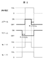
- FIG. 2 is a diagram showing a definition of dead time.
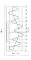
- FIG. 3 is a diagram showing a comparative example of a current waveform depending on whether or not a high frequency voltage is superimposed, and
- FIG. 4 is a diagram showing a comparative example of dead time compensation depending on whether or not a high frequency current is considered.
- the inverter In the inverter, if the upper arm and the lower arm are turned on at the same time, the DC voltage Vdc is directly applied to the IGBT, and the IGBT may be damaged. In order to prevent this, it is necessary to provide a time (dead time) for turning off both arms so that the upper arm and the lower arm do not turn on at the same time as shown in FIG.
- the voltage during the dead time is determined by the sign of the current of the motor.
- the sign of the current When the sign of the current is positive, the inverter output voltage becomes small, and conversely, when the sign of the current is negative, the inverter output voltage becomes large.
- the output voltage of the inverter is compensated according to the sign of the three-phase current.
- the dead time compensation cannot be appropriately performed due to the harmonics included in the detected current, so the current command value is used.
- high frequency voltage may be superimposed to reduce noise in the low speed range where there is a margin in output voltage.
- a high frequency current flows due to the superimposed high frequency voltage.
- the sign of the current changes due to this high frequency current, and the problem is that dead time compensation cannot be performed properly.
- the fundamental wave current is small, as shown in FIGS. 3 and 4, the sign of the current originally changes due to the high frequency current, but when the dead time compensation is performed according to the fundamental wave current command value, the dead time compensation is performed. Dead time compensation is off.
- the high frequency current value flowing by using the reverse model of the motor is estimated from the superimposed high frequency voltage, and the high frequency is higher than the fundamental wave current command value when determining the sign of the current in the dead time compensation. Add the current estimates.
- the calculation is performed using the inverse model of the motor.
- the reverse model of the motor it is possible to estimate the high frequency current with a simple calculation.
- the dead time compensation can be appropriately performed by the method of estimating the high frequency current by referring to the table.
- the dq-axis high-frequency voltage command values Vdh * and Vqh * superimpose a high-frequency component on the d-axis as in the equation (5), for example.
- the present invention may be configured by holding the amplitude Ih * and the phase ⁇ ih as a map with respect to the frequency ⁇ h of the high frequency voltage and referencing the table. The same result as is obtained.
- the magnetic pole position information is used according to the superimposed frequency ⁇ h by using a coordinate conversion means different from the fundamental wave current command value.
- the phase delay can be appropriately compensated. This makes it possible to prevent the phase of the dead time compensation from being out of phase due to the phase delay.
- the output voltage of the inverter may be compensated according to ** (estimated current for compensation for dead time). Since the high frequency voltage is superimposed to reduce noise in the low speed range where the output voltage has a margin, the dead time compensation of the inverter can be effectively performed.
- FIG. 5 is a diagram showing a modification of the dead time compensator
- FIG. 6 is a diagram showing a relationship between a dead time compensation U-phase current estimated value and a dead time compensation value in the dead time compensator of FIG. ..
- the dead time compensator (dead time compensating voltage calculation unit) 28 shown in FIG. 5 is a divider 41, 51, corresponding to each phase of the input three-phase current command values Iu **, Iv **, Iw **. It has 61, limiters 43, 53, 63 and dividers 45, 55, 65, respectively, and is dead with a predetermined inclination with respect to the three-phase current command values Iu **, Iv **, Iw **. Time compensation Three-phase voltage command values ⁇ Vu *, ⁇ Vv *, ⁇ Vw * are output.
- the dead time compensation voltage calculation unit (dead time compensator) 28 calculates according to the codes of the three-phase current command values Iu **, Iv **, and Iw **, but the dead time compensation voltage is calculated. As shown in FIGS. 5 and 6, the dead time compensation voltage is inclined with respect to the three-phase current command values Iu **, Iv **, and Iw ** so that the voltage does not switch suddenly at zero cross. It may be set as follows.
- FIG. 7 is a diagram showing another modification of the dead time compensator
- FIG. 8 is a diagram showing the relationship between the dead time compensation U-phase current estimated value and the dead time compensation value in the dead time compensator of FIG. 7. Is.
- the dead time compensator (dead time compensating voltage calculation unit) 28 shown in FIG. 7 is a divider 41, 51, corresponding to each phase of the input three-phase current command values Iu **, Iv **, Iw **. It has 61, dead zone setting units 47, 57, 67, and dividers 45, 55, 65, respectively, and the absolute values of the three-phase current command values Iu **, Iv **, and Iw ** are greater than the predetermined values. When it is small, the dead time compensation three-phase voltage command value ⁇ Vu *, ⁇ Vv *, ⁇ Vw * with a dead zone set to 0 is output.
- the three-phase current command values Iu **, Iv **, and Iw ** A method may be used in which a dead zone is provided in which the absolute value is set to 0 when the absolute value is smaller than a predetermined value.
- FIG. 9 is a diagram showing a schematic configuration of a vehicle in this embodiment.
- the vehicle of this embodiment includes a permanent magnet synchronous motor (PMSM) 1, a power converter (INV) 2, a direct current voltage source (BAT) 9, a motor control device 100, and a transmission ( The TM) 101, the differential gear (DEF) 103, the drive shaft 105, and the wheels 107 are provided.
- PMSM permanent magnet synchronous motor
- IVS power converter
- BAT direct current voltage source
- the TM the motor control device described in the first embodiment (FIG. 1) is used.
- the motor control device 100 controls the electric power supplied from the power converter (INV) 2 to the permanent magnet synchronous motor (PMSM) 1.
- a direct current voltage source (BAT) 9 such as a battery supplies power to the power converter (INV) 2.
- the permanent magnet synchronous motor (PMSM) 1 is connected to the transmission (TM) 101.
- the transmission (TM) 101 is connected to the drive shaft 105 via the differential gear (DEF) 103 to power the wheels 107.
- a method of superimposing a high frequency voltage may be used in order to reduce electromagnetic noise from the motor in the low speed range.
- the carrier frequency is high, the ratio of dead time to one cycle of PWM is relatively large, and it is also an application in which the importance of dead time compensation is high.
- the present invention is not limited to the above-described embodiment, but includes various modifications.
- the above embodiments have been described in detail to aid in understanding of the present invention and are not necessarily limited to those comprising all of the described configurations.
- it is possible to replace a part of the configuration of one embodiment with the configuration of another embodiment and it is also possible to add the configuration of another embodiment to the configuration of one embodiment.
Landscapes
- Engineering & Computer Science (AREA)
- Power Engineering (AREA)
- Life Sciences & Earth Sciences (AREA)
- Sustainable Development (AREA)
- Sustainable Energy (AREA)
- Transportation (AREA)
- Mechanical Engineering (AREA)
- Control Of Ac Motors In General (AREA)
- Inverter Devices (AREA)
Abstract
高周波電圧の重畳による低騒音化制御(あるいはセンサレス制御)が可能な電動機制御装置および電動機制御方法において、必要最小限の構成で、インバータのデッドタイム補償が可能な信頼性の高い電動機制御装置および電動機制御方法を提供する。基本波電圧指令値に高周波電圧指令値を加算して電圧指令値を出力する高周波電圧重畳部と、前記高周波電圧指令値から高周波電流値を推定する高周波電流推定値演算部と、前記高周波電流推定値演算部で推定した高周波電流推定値を基本波電流指令値に加算するデッドタイム補償用電流推定値演算部と、前記デッドタイム補償用電流推定値演算部で算出したデッドタイム補償用電流推定値に応じてインバータの出力電圧を補償するデッドタイム補償電圧演算部と、を備えることを特徴とする。
Description
本発明は、モータ制御装置の構成とその制御方法に係り、特に、モータの低騒音化制御に適用して有効な技術に関する。
自動車用モータでは、静粛性を高めるために、ノイズの伝搬を抑えるための吸音材や遮音材の追加といった受動的な騒音低減技術とともに、例えばインバータから一定の電圧を重畳することによってモータに生じる逆起電圧の歪みを正弦波にして騒音を低減する能動的な騒音低減技術が検討されている。
また、産業用インバータ等の多くのアプリケーションにおいて、モータのトルクに直接寄与しない高周波電圧を重畳することで、流れる高周波電流からモータの回転角を推定するセンサレス制御が適用されている。
しかしながら、高周波電圧を重畳する制御を適用した場合、重畳した高周波電圧によって流れる高周波電流の影響によりインバータのデッドタイムを正しく補償できない可能性がある。
本技術分野の背景技術として、例えば、特許文献1のような技術がある。特許文献1では、電流制御系と別に回転角の推定のために高周波電圧を重畳している。
一方、インバータのデッドタイムによる電圧誤差を補償する技術として、モータの三相基本波電流指令値からデッドタイム補償量を演算する手法が用いられている。例えば、特許文献2では、高調波電流によってデッドタイム補償が適切にできなくなるのを防ぐために、低電流時にトルクに寄与しない無効電流を流している。
上記特許文献1によれば、高トルク運転時でも電動機の運転を持続しつつ、回転子の回転状態を検出するためのセンサを用いずに回転子の回転状態を精度よく検出することができる。
しかしながら、高周波を重畳する影響で、デッドタイム補償を適切に行うことができず、デッドタイムに起因した騒音やトルクリプルが発生する恐れがある。
また、上記特許文献2によれば、高周波電圧を重畳した状態でもデッドタイム補償を適切に行うことが可能になるが、一方で、無効電流により電力損失が増加する。
そこで、本発明の目的は、高周波電圧の重畳による低騒音化制御(あるいはセンサレス制御)が可能な電動機制御装置および電動機制御方法において、必要最小限の構成で、インバータのデッドタイム補償が可能な信頼性の高い電動機制御装置および電動機制御方法を提供することにある。
上記課題を解決するために、本発明は、基本波電圧指令値に高周波電圧指令値を加算して電圧指令値を出力する高周波電圧重畳部と、前記高周波電圧指令値から高周波電流値を推定する高周波電流推定値演算部と、前記高周波電流推定値演算部で推定した高周波電流推定値を基本波電流指令値に加算するデッドタイム補償用電流推定値演算部と、前記デッドタイム補償用電流推定値演算部で算出したデッドタイム補償用電流推定値に応じてインバータの出力電圧を補償するデッドタイム補償電圧演算部と、を備えることを特徴とする。
また、本発明は、基本波電圧指令値に高周波電圧指令値を加算して電圧指令値を出力し、前記高周波電圧指令値から高周波電流値を推定し、前記推定した高周波電流推定値を基本波電流指令値に加算し、前記加算した結果に応じてインバータの出力電圧を補償することを特徴とする。
本発明によれば、高周波電圧の重畳による低騒音化制御(あるいはセンサレス制御)が可能な電動機制御装置および電動機制御方法において、必要最小限の構成で、インバータのデッドタイム補償が可能な信頼性の高い電動機制御装置および電動機制御方法を実現することができる。
これにより、モータ駆動時の騒音低減と信頼性向上が図れる。
上記した以外の課題、構成及び効果は、以下の実施形態の説明により明らかにされる。
以下、図面を用いて本発明の実施例を説明する。なお、各図面において同一の構成については同一の符号を付し、重複する部分についてはその詳細な説明は省略する。
また、以下の説明では永久磁石同期モータ(PMSM:Permanent Magnet Synchronous Motor)を対象としているが、本発明はこれに限定されるものではなく、シンクロリラクタンスモータや永久磁石同期発電機、巻線型同期機、誘導モータ、誘導発電機等、交流機であれば同様の効果が得られる。また、インバータ装置の半導体スイッチング素子はIGBTを対象としているが、本発明はこれに限定されるものではなく、MOSFETでもよいし、その他の電力用半導体素子でもよい。
図1から図8を参照して、本発明の実施例1に係る電動機制御装置及び電動機制御方法について説明する。図1は、本実施例におけるモータ制御装置の全体構成を示すブロック図である。
本実施例のモータ制御装置は、図1に示すように、電力変換器2と、相電流検出手段3と、磁極位置検出器4と、周波数演算部5と、直流電圧検出部6と、座標変換部7と、電流制御器10と、高周波電圧重畳部12と、位相遅れ補償器14と、座標変換部16と、座標変換部18と、高周波用位相遅れ補償器20と、高周波電流推定値演算部22と、座標変換部24と、デッドタイム補償用電流推定値演算部26と、デッドタイム補償電圧演算部(デッドタイム補償器)28と、デッドタイム補償部30と、PWM制御器32を備えて構成されている。
電力変換器2は、直流電圧源9(例えばバッテリ)からの直流電力を後述するゲート信号に従って交流電力に変換して永久磁石同期モータ(PMSM)1を駆動する。
相電流検出手段3は、ホールCT(Current Transformer)等から成り、電力変換器2からPMSM1に流れるU相,V相,W相の3相の電流波形Iuc,Ivc,Iwcを検出する。
磁極位置検出器4は、レゾルバ等から成り、PMSM1の磁極位置を検出して磁極位置情報θを出力する。
周波数演算部5は、磁極位置検出器4で検出された磁極位置情報θから、例えば微分演算によって速度情報ω1を出力する。
座標変換部7は、相電流検出手段3で検出した電流波形Iuc,Ivc,Iwcを磁極位置検出器4で検出した磁極位置情報θで座標変換してdq軸電流検出値Idc,Iqcを出力する。
電流制御器10は、例えばPI制御器等で構成されdq軸基本波電流指令値Id*,Iq*とdq軸電流検出値Idc,Iqcが一致するようにdq軸基本波電圧指令値Vd*,Vq*を出力する。
高周波電圧重畳部12は、dq軸基本波電圧指令値Vd*,Vq*にdq軸高周波電圧指令値Vdh*,Vqh*を加算してdq軸電圧指令値Vd**,Vq**を出力する。
位相遅れ補償器14は、磁極位置情報θに対して速度情報ω1を用いて、制御遅れ分を補正して電圧用磁極位置θvを出力する。制御遅れは磁極位置を検出してから、三相電圧に反映されるまでの時間であり、例えば、三角波比較PWMでは制御周期Δtに対して、式(1)に示すように制御周期1.5周期分の遅れ補償を行う。
座標変換部16は、高周波電圧重畳部12で出力したdq軸電圧指令値Vd**,Vq**を位相遅れ補償器14で演算された電圧用磁極位置θvで座標変換して三相基本波電圧指令値Vu*,Vv*,Vw*を出力する。
座標変換部18は、dq軸基本波電流指令値Id*,Iq*を電圧用磁極位置θvで座標変換して三相基本波電流指令値Iu*,Iv*,Iw*を出力する。
高周波電流推定値演算部22は、dq軸高周波電圧指令値Vdh*,Vqh*から例えば、式(2)のようにモータの逆モデルを用いて高周波電流推定値Idh*,Iqh*を演算する。逆モデルを用いることで簡単に演算することができる。

高周波用位相遅れ補償器20は、磁極位置情報θに対して速度情報ω1を用いて、制御遅れ分を補正して高周波用磁極位置θhを出力する。制御遅れは磁極位置を検出してから、三相電圧に反映されるまでの時間であり、例えば、三角波比較PWMでは制御周期に対して、制御周期1.5周期分の遅れ補償を行う。位相遅れ補償器14との違いは、高周波用位相遅れ補償器20では式(3)に示すように高周波の周波数ωhを考慮して遅れ補償を行う。
座標変換部24は、高周波電流推定値演算部22で演算したdq軸高周波電流推定値Idh*,Iqh*を高周波用位相遅れ補償器20で演算された高周波用磁極位置θhで座標変換して三相高周波電流推定値Iuh*,Ivh*,Iwh*を出力する。
なお、dq軸基本波電流指令値Id*,Iq*を座標変換する座標変換部18で用いる位相と、dq軸高周波電流推定値Idh*,Iqh*を座標変換する座標変換部24で用いる位相は、それぞれ異なる値を用いるのが望ましい。異なる値を用いることで、位相遅れを適切に補償することができる。
デッドタイム補償用電流推定値演算部26は、三相基本波電流指令値Iu*,Iv*,Iw*と三相高周波電流推定値Iuh*,Ivh*,Iwh*を加算して三相電流指令値Iu**,Iv**,Iw**を出力する。
デッドタイム補償電圧演算部(デッドタイム補償器)28は、式(4)のように三相電流指令値Iu**,Iv**,Iw**の符号に応じてデッドタイム補償三相電圧指令値ΔVu*,ΔVv*,ΔVw*を出力する。

但し、Vdcはインバータ直流電圧情報、Tdはデッドタイム、fcはPWMキャリア周波数、Signは符号をそれぞれ表す。
デッドタイム補償部30は、三相基本波電圧指令値Vu*,Vv*,Vw*にデッドタイム補償三相電圧指令値ΔVu*,ΔVv*,ΔVw*を加算して三相電圧指令値Vu**,Vv**,Vw**を出力する。
直流電圧検出部6は、直流電圧源9の電圧を検出して直流電圧情報Vdcを出力する。
PWM制御器32は、三相電圧指令値Vu**,Vv**,Vw**と直流電圧情報Vdcを用いて例えば三角波比較を行ってゲート信号を出力する。
図2から図4を用いて、本発明の原理と効果を説明する。図2は、デッドタイムの定義を示す図である。図3は、高周波電圧の重畳有無による電流波形の比較例を示す図であり、図4は、高周波電流の考慮有無によるデッドタイム補償の比較例を示す図である。
インバータでは上アームと下アームを同時にONすると直流電圧Vdcが直接IGBTにかかり、IGBTが損傷する恐れがある。それを防ぐために、図2のように上アームと下アームが同時にONしないように両方のアームをオフする時間(デッドタイム)を設ける必要がある。
デッドタイム中の電圧はモータの電流の符号によって決まり、電流の符号が正の時、インバータ出力電圧は小さくなり、逆に電流の符号が負の時、インバータ出力電圧は大きくなる。デッドタイムによる出力電圧の誤差を補償するために、三相電流の符号に応じてインバータの出力電圧を補償する。一般的に検出電流を用いると検出電流に含まれる高調波によってデッドタイム補償が適切に行うことができないため、電流指令値を用いる。
一方、出力電圧に余裕がある低速域において騒音低減のために高周波電圧が重畳されることがある。この時、重畳した高周波電圧によって高周波電流が流れる。この高周波電流によって電流の符号が変化し、デッドタイム補償が適切に行えないことが問題になる。特に、基本波電流が小さい場合、図3及び図4に示すように、高周波電流によって本来は電流の符号が変化するのに対して、基本波電流指令値に応じてデッドタイム補償を行うと、デッドタイム補償がずれてしまう。
そこで、本発明では、重畳している高周波電圧からモータの逆モデルを用いて流れる高周波電流値を推定して、デッドタイム補償における電流の符号を判定する際に基本波電流指令値に対して高周波電流推定値を加算する。
これによって、デッドタイム補償に用いる電流の符号に高周波の情報を反映できる。特に、基本波電流が小さい場合に高周波電流が適切に流れず、騒音低減ができないことを防ぐことができる。
本発明では、高周波電流の推定において、モータの逆モデルを用いて演算している。モータの逆モデルを用いることで、簡単な演算で高周波電流を推定することが可能である。
一方、モータの逆モデルの代わりに、テーブルを参照して高周波電流を推定する方法でも同様にデッドタイム補償を適切に行うことができる。例えば、dq軸高周波電圧指令値Vdh*,Vqh*は例えば、式(5)のようにd軸に高周波成分を重畳する。
この時、dq軸高周波電流推定値Idh*,Iqh*は式(6)となる。

振幅Ih*と位相θihは高周波電圧の周波数ωhに応じて変化するので、高周波電圧の周波数ωhに対して振幅Ih*と位相θihをマップとして保持し、テーブル参照する形で構成しても本発明と同様の結果が得られる。
また、本発明で示したように、高周波電流推定値を座標変換する際には、基本波電流指令値とは別の座標変換手段を用いて、重畳している周波数ωhに応じて磁極位置情報を遅れ補償することで、位相遅れを適切に補償することができる。これにより位相遅れによってデッドタイム補償の位相がずれることを防ぐことができる。
なお、dq軸基本波電流指令値Id*,Iq*が一定値以下の低電流時のみデッドタイム補償用電流推定値演算部26で算出した三相電流指令値Iu**,Iv**,Iw**(デッドタイム補償用電流推定値)に応じてインバータの出力電圧を補償するようにしてもよい。出力電圧に余裕がある低速域において騒音低減のために高周波電圧が重畳されるため、効果的にインバータのデッドタイム補償を行うことができる。
≪変形例1≫
図5及び図6を参照して、デッドタイム補償電圧演算部(デッドタイム補償器)28の変形例を説明する。図5は、デッドタイム補償器の変形例を示す図であり、図6は、図5のデッドタイム補償器におけるデッドタイム補償用U相電流推定値とデッドタイム補償値の関係を示す図である。
図5及び図6を参照して、デッドタイム補償電圧演算部(デッドタイム補償器)28の変形例を説明する。図5は、デッドタイム補償器の変形例を示す図であり、図6は、図5のデッドタイム補償器におけるデッドタイム補償用U相電流推定値とデッドタイム補償値の関係を示す図である。
図5に示すデッドタイム補償器(デッドタイム補償電圧演算部)28は、入力される三相電流指令値Iu**,Iv**,Iw**の各相に対応する除算器41,51,61とリミッタ43,53,63と除算器45,55,65を各々有しており、三相電流指令値Iu**,Iv**,Iw**に対して所定の傾きを持たせたデッドタイム補償三相電圧指令値ΔVu*,ΔVv*,ΔVw*を出力する。
上述した本実施例では、デッドタイム補償電圧演算部(デッドタイム補償器)28は三相電流指令値Iu**,Iv**,Iw**の符号に応じて演算したが、デッドタイム補償電圧がゼロクロスで急激に切り替わらないようにするため、図5及び図6に示すように、デッドタイム補償電圧を三相電流指令値Iu**,Iv**,Iw**に対して傾きを持たせるように設定してもよい。
≪変形例2≫
図7及び図8を参照して、デッドタイム補償電圧演算部(デッドタイム補償器)28の別の変形例を説明する。図7は、デッドタイム補償器の別の変形例を示す図であり、図8は、図7のデッドタイム補償器におけるデッドタイム補償用U相電流推定値とデッドタイム補償値の関係を示す図である。
図7及び図8を参照して、デッドタイム補償電圧演算部(デッドタイム補償器)28の別の変形例を説明する。図7は、デッドタイム補償器の別の変形例を示す図であり、図8は、図7のデッドタイム補償器におけるデッドタイム補償用U相電流推定値とデッドタイム補償値の関係を示す図である。
図7に示すデッドタイム補償器(デッドタイム補償電圧演算部)28は、入力される三相電流指令値Iu**,Iv**,Iw**の各相に対応する除算器41,51,61と不感帯設定部47,57,67と除算器45,55,65を各々有しており、三相電流指令値Iu**,Iv**,Iw**の絶対値が所定の値よりも小さい時には0にする不感帯を持たせたデッドタイム補償三相電圧指令値ΔVu*,ΔVv*,ΔVw*を出力する。
変形例1と同様に、デッドタイム補償電圧がゼロクロスで急激に切り替わらないようにするため、図7及び図8に示すように、三相電流指令値Iu**,Iv**,Iw**の絶対値が所定の値よりも小さい時には0にするという不感帯を持たせる方式であっても良い。
図9を参照して、本発明の実施例2に係る車両について説明する。図9は、本実施例における車両の概略構成を示す図である。
本実施例の車両は、図9に示すように、永久磁石同期モータ(PMSM)1と、電力変換器(INV)2と、直流電圧源(BAT)9と、モータ制御装置100と、トランスミッション(TM)101と、ディファシャルギア(DEF)103と、ドライブシャフト105と、車輪107を備えて構成されている。モータ制御装置100には、実施例1(図1)で説明したモータ制御装置が用いられている。
実施例1で説明したように、モータ制御装置100は、電力変換器(INV)2から永久磁石同期モータ(PMSM)1に供給する電力を制御する。例えばバッテリなどの直流電圧源(BAT)9は電力変換器(INV)2に電力を供給する。永久磁石同期モータ(PMSM)1はトランスミッション(TM)101に接続される。トランスミッション(TM)101はディファシャルギアルギア(DEF)103を介してドライブシャフト105に接続され、車輪107に動力を供給する。
なお、トランスミッション(TM)101が無く、永久磁石同期モータ(PMSM)1が直接ディファレンシャルギア(DEF)103に接続される構成や、前輪、後輪それぞれに永久磁石同期モータ(PMSM)1及び電力変換器(INV)2が適用される構成でもよい。
自動車では低速域でモータからの電磁騒音を低減するため、高周波電圧を重畳する方式が用いられることがある。また、キャリア周波数が高いためPWMの一周期に占めるデッドタイムの割合が相対的に大きく、デッドタイム補償の重要度が高いアプリケーションでもある。本発明を適用することで、自動車において電磁騒音を低減した制御の効果をデッドタイムによって阻害されるのを防ぐことができ、運転者が快適に運転できるようになる。
なお、本発明は上記した実施例に限定されるものではなく、様々な変形例が含まれる。例えば、上記の実施例は本発明に対する理解を助けるために詳細に説明したものであり、必ずしも説明した全ての構成を備えるものに限定されるものではない。また、ある実施例の構成の一部を他の実施例の構成に置き換えることが可能であり、また、ある実施例の構成に他の実施例の構成を加えることも可能である。また、各実施例の構成の一部について、他の構成の追加・削除・置換をすることが可能である。
1:永久磁石同期モータ(PMSM)、2:電力変換器(INV)、3:相電流検出手段、4:磁極位置検出器、5:周波数演算部、6:直流電圧検出部、7,16,18,24:座標変換部、9:直流電圧源(BAT)、10:電流制御器、12:高周波電圧重畳部、14:位相遅れ補償器、20:高周波用位相遅れ補償器、22:高周波電流推定値演算部、26:デッドタイム補償用電流推定値演算部、28:デッドタイム補償電圧演算部(デッドタイム補償器)、30:デッドタイム補償部、32:PWM制御器、39:ゲイン、41,51,61:除算器、43,53,63:リミッタ、45,55,65:乗算器、47,57,67:不感帯設定部、100:モータ制御装置、101:トランスミッション(TM)、103:ディファシャルギア(DEF)、105:ドライブシャフト、107:車輪
Claims (13)
- 基本波電圧指令値に高周波電圧指令値を加算して電圧指令値を出力する高周波電圧重畳部と、
前記高周波電圧指令値から高周波電流値を推定する高周波電流推定値演算部と、
前記高周波電流推定値演算部で推定した高周波電流推定値を基本波電流指令値に加算するデッドタイム補償用電流推定値演算部と、
前記デッドタイム補償用電流推定値演算部で算出したデッドタイム補償用電流推定値に応じてインバータの出力電圧を補償するデッドタイム補償電圧演算部と、
を備える電動機制御装置。 - 請求項1に記載の電動機制御装置において、
前記高周波電流推定値演算部は、制御の対象となる電動機の逆モデルを用いて前記高周波電圧指令値から高周波電流推定値を算出する電動機制御装置。 - 請求項1または2に記載の電動機制御装置において、
座標変換に用いる位相を前記基本波電流指令値と前記高周波電流推定値で異なる値を用いる電動機制御装置。 - 請求項1に記載の電動機制御装置において、
前記デッドタイム補償電圧演算部は、入力される三相電流指令値の各相に対応するリミッタを各々有し、
前記三相電流指令値に対して所定の傾きを持たせたデッドタイム補償電圧を出力する電動機制御装置。 - 請求項1に記載の電動機制御装置において、
前記デッドタイム補償電圧演算部は、入力される三相電流指令値の各相に対応する不感帯設定部を各々有し、
前記三相電流指令値の絶対値が所定の値よりも小さい時には0にする不感帯を持たせたデッドタイム補償電圧を出力する電動機制御装置。 - 請求項1に記載の電動機制御装置において、
基本波電流が一定値以下の低電流時のみ前記デッドタイム補償用電流推定値演算部で算出したデッドタイム補償用電流推定値に応じてインバータの出力電圧を補償する電動機制御装置。 - 電動機を駆動する電動機制御装置を搭載する車両において、
請求項1から6のいずれか1項に記載の電動機制御装置を用いる車両。 - 基本波電圧指令値に高周波電圧指令値を加算して電圧指令値を出力し、
前記高周波電圧指令値から高周波電流値を推定し、
前記推定した高周波電流推定値を基本波電流指令値に加算し、
前記加算した結果に応じてインバータの出力電圧を補償する電動機制御方法。 - 請求項8に記載の電動機制御方法において、
制御の対象となる電動機の逆モデルを用いて前記高周波電圧指令値から高周波電流推定値を算出する電動機制御方法。 - 請求項8または9に記載の電動機制御方法において、
座標変換に用いる位相を前記基本波電流指令値と前記高周波電流推定値で異なる値を用いる電動機制御方法。 - 請求項8に記載の電動機制御方法において、
三相電流指令値に対して所定の傾きを持たせたデッドタイム補償電圧を出力し、前記基本波電圧指令値に加算する電動機制御方法。 - 請求項8に記載の電動機制御方法において、
三相電流指令値の絶対値が所定の値よりも小さい時には0にする不感帯を持たせたデッドタイム補償電圧を出力し、前記基本波電圧指令値に加算する電動機制御方法。 - 請求項8に記載の電動機制御方法において、
基本波電流が一定値以下の低電流時のみ前記加算した結果に応じてインバータの出力電圧を補償する電動機制御方法。
Priority Applications (3)
| Application Number | Priority Date | Filing Date | Title |
|---|---|---|---|
| US18/012,419 US20230246579A1 (en) | 2020-09-25 | 2021-04-20 | Electric motor control device, vehicle, and electric motor control method |
| EP21871885.6A EP4220930A1 (en) | 2020-09-25 | 2021-04-20 | Electric motor control device, vehicle, and electric motor control method |
| CN202180049271.4A CN115843415A (zh) | 2020-09-25 | 2021-04-20 | 电动机控制装置和车辆、电动机控制方法 |
Applications Claiming Priority (2)
| Application Number | Priority Date | Filing Date | Title |
|---|---|---|---|
| JP2020160381A JP2022053640A (ja) | 2020-09-25 | 2020-09-25 | 電動機制御装置および車両、電動機制御方法 |
| JP2020-160381 | 2020-09-25 |
Publications (1)
| Publication Number | Publication Date |
|---|---|
| WO2022064750A1 true WO2022064750A1 (ja) | 2022-03-31 |
Family
ID=80845166
Family Applications (1)
| Application Number | Title | Priority Date | Filing Date |
|---|---|---|---|
| PCT/JP2021/016036 WO2022064750A1 (ja) | 2020-09-25 | 2021-04-20 | 電動機制御装置および車両、電動機制御方法 |
Country Status (5)
| Country | Link |
|---|---|
| US (1) | US20230246579A1 (ja) |
| EP (1) | EP4220930A1 (ja) |
| JP (1) | JP2022053640A (ja) |
| CN (1) | CN115843415A (ja) |
| WO (1) | WO2022064750A1 (ja) |
Citations (4)
| Publication number | Priority date | Publication date | Assignee | Title |
|---|---|---|---|---|
| JP2012165608A (ja) * | 2011-02-09 | 2012-08-30 | Denso Corp | 回転機の制御装置 |
| JP5401500B2 (ja) | 2011-04-19 | 2014-01-29 | 株式会社日立産機システム | 電力変換装置、電動機制御システム |
| WO2018016476A1 (ja) * | 2016-07-20 | 2018-01-25 | 日本精工株式会社 | 電動パワーステアリング装置 |
| WO2018016356A1 (ja) * | 2016-07-20 | 2018-01-25 | 日本精工株式会社 | 電動パワーステアリング装置 |
-
2020
- 2020-09-25 JP JP2020160381A patent/JP2022053640A/ja active Pending
-
2021
- 2021-04-20 CN CN202180049271.4A patent/CN115843415A/zh active Pending
- 2021-04-20 US US18/012,419 patent/US20230246579A1/en active Pending
- 2021-04-20 EP EP21871885.6A patent/EP4220930A1/en active Pending
- 2021-04-20 WO PCT/JP2021/016036 patent/WO2022064750A1/ja unknown
Patent Citations (4)
| Publication number | Priority date | Publication date | Assignee | Title |
|---|---|---|---|---|
| JP2012165608A (ja) * | 2011-02-09 | 2012-08-30 | Denso Corp | 回転機の制御装置 |
| JP5401500B2 (ja) | 2011-04-19 | 2014-01-29 | 株式会社日立産機システム | 電力変換装置、電動機制御システム |
| WO2018016476A1 (ja) * | 2016-07-20 | 2018-01-25 | 日本精工株式会社 | 電動パワーステアリング装置 |
| WO2018016356A1 (ja) * | 2016-07-20 | 2018-01-25 | 日本精工株式会社 | 電動パワーステアリング装置 |
Also Published As
| Publication number | Publication date |
|---|---|
| EP4220930A1 (en) | 2023-08-02 |
| US20230246579A1 (en) | 2023-08-03 |
| JP2022053640A (ja) | 2022-04-06 |
| CN115843415A (zh) | 2023-03-24 |
Similar Documents
| Publication | Publication Date | Title |
|---|---|---|
| JP3746377B2 (ja) | 交流電動機の駆動制御装置 | |
| EP2779414B1 (en) | Motor control system having bandwidth compensation | |
| JP4065903B2 (ja) | 誘導電動機のベクトル制御装置、誘導電動機のベクトル制御方法および誘導電動機の駆動制御装置 | |
| JP4604820B2 (ja) | モータ駆動システムの制御装置 | |
| US20100259207A1 (en) | Control apparatus of alternating-current motor | |
| JP3783695B2 (ja) | モーター制御装置 | |
| JP2011147287A (ja) | 電動機の磁極位置推定装置 | |
| US20170264227A1 (en) | Inverter control device and motor drive system | |
| JP7270391B2 (ja) | 電力変換装置の制御装置および電動機駆動システム | |
| US9419555B2 (en) | Synchronous machine control apparatus | |
| JP2013172594A (ja) | 交流電動機の制御装置 | |
| WO2015125586A1 (en) | Power converter control apparatus and motor system having the same | |
| JP7280170B2 (ja) | モータ制御装置、モータ制御方法、ハイブリッドシステム、昇圧コンバータシステム、電動パワーステアリングシステム | |
| WO2013035382A1 (ja) | 同期電動機の制御システム | |
| US20230336098A1 (en) | Motor control device and motor control method | |
| US8749184B2 (en) | Control apparatus for electric motor | |
| JP7158573B2 (ja) | 電力変換装置およびそれを備えた電動車両システム | |
| JP3939481B2 (ja) | 交流モータの制御装置 | |
| WO2022064750A1 (ja) | 電動機制御装置および車両、電動機制御方法 | |
| JP2004289927A (ja) | モーター制御装置 | |
| JP2010268599A (ja) | 永久磁石モータの制御装置 | |
| KR102409792B1 (ko) | 영구 자석 동기 전동기의 제어 장치, 마이크로 컴퓨터, 전동기 시스템 및 영구 자석 동기 전동기의 운전 방법 | |
| JP7053335B2 (ja) | モータ制御装置、電動車両 | |
| JP6837259B2 (ja) | 三相同期電動機の制御装置並びにそれを用いる電動パワーステアリング装置 | |
| JP7385776B2 (ja) | 電動機の制御装置 |
Legal Events
| Date | Code | Title | Description |
|---|---|---|---|
| 121 | Ep: the epo has been informed by wipo that ep was designated in this application |
Ref document number: 21871885 Country of ref document: EP Kind code of ref document: A1 |
|
| NENP | Non-entry into the national phase |
Ref country code: DE |
|
| ENP | Entry into the national phase |
Ref document number: 2021871885 Country of ref document: EP Effective date: 20230425 |