WO2022059385A1 - スタブシャフト、動力伝達軸およびスタブシャフトの製造方法 - Google Patents
スタブシャフト、動力伝達軸およびスタブシャフトの製造方法 Download PDFInfo
- Publication number
- WO2022059385A1 WO2022059385A1 PCT/JP2021/029489 JP2021029489W WO2022059385A1 WO 2022059385 A1 WO2022059385 A1 WO 2022059385A1 JP 2021029489 W JP2021029489 W JP 2021029489W WO 2022059385 A1 WO2022059385 A1 WO 2022059385A1
- Authority
- WO
- WIPO (PCT)
- Prior art keywords
- shaft
- outer diameter
- stub shaft
- rotation axis
- thermosetting
- Prior art date
- Legal status (The legal status is an assumption and is not a legal conclusion. Google has not performed a legal analysis and makes no representation as to the accuracy of the status listed.)
- Ceased
Links
Images

Classifications
-
- F—MECHANICAL ENGINEERING; LIGHTING; HEATING; WEAPONS; BLASTING
- F16—ENGINEERING ELEMENTS AND UNITS; GENERAL MEASURES FOR PRODUCING AND MAINTAINING EFFECTIVE FUNCTIONING OF MACHINES OR INSTALLATIONS; THERMAL INSULATION IN GENERAL
- F16C—SHAFTS; FLEXIBLE SHAFTS; ELEMENTS OR CRANKSHAFT MECHANISMS; ROTARY BODIES OTHER THAN GEARING ELEMENTS; BEARINGS
- F16C3/00—Shafts; Axles; Cranks; Eccentrics
- F16C3/02—Shafts; Axles
-
- C—CHEMISTRY; METALLURGY
- C21—METALLURGY OF IRON
- C21D—MODIFYING THE PHYSICAL STRUCTURE OF FERROUS METALS; GENERAL DEVICES FOR HEAT TREATMENT OF FERROUS OR NON-FERROUS METALS OR ALLOYS; MAKING METAL MALLEABLE, e.g. BY DECARBURISATION OR TEMPERING
- C21D9/00—Heat treatment, e.g. annealing, hardening, quenching or tempering, adapted for particular articles; Furnaces therefor
- C21D9/28—Heat treatment, e.g. annealing, hardening, quenching or tempering, adapted for particular articles; Furnaces therefor for plain shafts
-
- C—CHEMISTRY; METALLURGY
- C21—METALLURGY OF IRON
- C21D—MODIFYING THE PHYSICAL STRUCTURE OF FERROUS METALS; GENERAL DEVICES FOR HEAT TREATMENT OF FERROUS OR NON-FERROUS METALS OR ALLOYS; MAKING METAL MALLEABLE, e.g. BY DECARBURISATION OR TEMPERING
- C21D9/00—Heat treatment, e.g. annealing, hardening, quenching or tempering, adapted for particular articles; Furnaces therefor
- C21D9/50—Heat treatment, e.g. annealing, hardening, quenching or tempering, adapted for particular articles; Furnaces therefor for welded joints
-
- F—MECHANICAL ENGINEERING; LIGHTING; HEATING; WEAPONS; BLASTING
- F16—ENGINEERING ELEMENTS AND UNITS; GENERAL MEASURES FOR PRODUCING AND MAINTAINING EFFECTIVE FUNCTIONING OF MACHINES OR INSTALLATIONS; THERMAL INSULATION IN GENERAL
- F16C—SHAFTS; FLEXIBLE SHAFTS; ELEMENTS OR CRANKSHAFT MECHANISMS; ROTARY BODIES OTHER THAN GEARING ELEMENTS; BEARINGS
- F16C3/00—Shafts; Axles; Cranks; Eccentrics
- F16C3/02—Shafts; Axles
- F16C3/023—Shafts; Axles made of several parts, e.g. by welding
-
- F—MECHANICAL ENGINEERING; LIGHTING; HEATING; WEAPONS; BLASTING
- F16—ENGINEERING ELEMENTS AND UNITS; GENERAL MEASURES FOR PRODUCING AND MAINTAINING EFFECTIVE FUNCTIONING OF MACHINES OR INSTALLATIONS; THERMAL INSULATION IN GENERAL
- F16D—COUPLINGS FOR TRANSMITTING ROTATION; CLUTCHES; BRAKES
- F16D1/00—Couplings for rigidly connecting two coaxial shafts or other movable machine elements
- F16D1/06—Couplings for rigidly connecting two coaxial shafts or other movable machine elements for attachment of a member on a shaft or on a shaft-end
- F16D1/064—Couplings for rigidly connecting two coaxial shafts or other movable machine elements for attachment of a member on a shaft or on a shaft-end non-disconnectable
- F16D1/068—Couplings for rigidly connecting two coaxial shafts or other movable machine elements for attachment of a member on a shaft or on a shaft-end non-disconnectable involving gluing, welding or the like
-
- F—MECHANICAL ENGINEERING; LIGHTING; HEATING; WEAPONS; BLASTING
- F16—ENGINEERING ELEMENTS AND UNITS; GENERAL MEASURES FOR PRODUCING AND MAINTAINING EFFECTIVE FUNCTIONING OF MACHINES OR INSTALLATIONS; THERMAL INSULATION IN GENERAL
- F16D—COUPLINGS FOR TRANSMITTING ROTATION; CLUTCHES; BRAKES
- F16D3/00—Yielding couplings, i.e. with means permitting movement between the connected parts during the drive
- F16D3/16—Universal joints in which flexibility is produced by means of pivots or sliding or rolling connecting parts
- F16D3/20—Universal joints in which flexibility is produced by means of pivots or sliding or rolling connecting parts one coupling part entering a sleeve of the other coupling part and connected thereto by sliding or rolling members
-
- F—MECHANICAL ENGINEERING; LIGHTING; HEATING; WEAPONS; BLASTING
- F16—ENGINEERING ELEMENTS AND UNITS; GENERAL MEASURES FOR PRODUCING AND MAINTAINING EFFECTIVE FUNCTIONING OF MACHINES OR INSTALLATIONS; THERMAL INSULATION IN GENERAL
- F16C—SHAFTS; FLEXIBLE SHAFTS; ELEMENTS OR CRANKSHAFT MECHANISMS; ROTARY BODIES OTHER THAN GEARING ELEMENTS; BEARINGS
- F16C2326/00—Articles relating to transporting
- F16C2326/01—Parts of vehicles in general
- F16C2326/06—Drive shafts
Definitions
- the present invention relates to a stub shaft, a power transmission shaft, and a method for manufacturing the stub shaft.
- Patent Document 1 discloses a propeller shaft including a pipe portion connected to a rotating shaft that transmits a driving force of a vehicle and a stub shaft that receives a rotational force from the pipe portion.
- the stub shaft has a flange portion welded to the pipe portion and a shaft portion connected to the flange portion.
- An object of the present invention is to provide a method for manufacturing a stub shaft, a power transmission shaft, and a stub shaft, which can reduce the weight of the entire shaft while ensuring the strength of the shaft portion.
- the shaft portion connected to the flange portion has a first outer diameter portion and a second outer diameter portion having a diameter smaller than that of the first outer diameter portion
- the heat curing portion includes a heat curing portion.
- the part where the virtual line forming an angle with the rotation axis is 45 degrees overlaps the surface between the flange part and the shaft part is the boundary part, and the direction along the rotation axis is the axial direction. When this is done, it is provided on the side of the shaft portion with respect to the boundary portion in the axial direction.
- the overall weight can be reduced while ensuring the strength of the shaft portion.
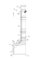
- FIG. It is a side view which shows by cutting a part of the propeller shaft 1 of Embodiment 1.
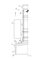
- FIG. It is a side view which shows by cutting a part of the stub shaft 10 of Embodiment 1.
- FIG. It is a figure which shows the process of forming the thermosetting part 17 in the manufacturing method of the stub shaft 10 of Embodiment 1.
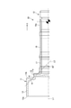
- FIG. It is a side view which shows by cutting a part of the stub shaft 20 of Embodiment 2.
- FIG. 1 is a side view showing a partially cut portion of the propeller shaft 1 of the first embodiment.
- the propeller shaft 1 as a power transmission shaft transmits the rotation of the engine, which is a drive source of the vehicle, to the drive wheels, and is interposed between the input shaft 2 and the output shaft 3.
- the input shaft 2 is a vehicle-side rotating shaft portion connected to a transmission (not shown) on the engine side.
- the output shaft 3 is connected to a differential gear (not shown) on the drive wheel side.
- the input shaft 2 and the output shaft 3 are arranged coaxially.
- the propeller shaft 1 includes a shaft 4, a first constant velocity joint 5, and a second constant velocity joint 6.
- the shaft 4 is arranged on a concentric circle with the rotation axes of the input shaft 2 and the output shaft 3.
- the rotation axis common to the input shaft 2, the output shaft 3 and the shaft 4 is referred to as the rotation axis L1
- the direction along the rotation axis L1 is the axial direction
- the radiation direction with respect to the rotation axis L1 is the radial direction
- the X-axis is set in the axial direction, and in the axial direction, the direction from the input axis 2 to the output axis 3 is the X-axis positive direction
- the opposite direction is the X-axis negative direction.
- the first constant velocity joint 5 is provided at the X-axis negative end of the shaft 4 in the X-axis direction, and connects the input shaft 2 and the shaft 4 so as to be rotatable integrally.
- the second constant velocity joint 6 is provided at the X-axis positive end of the shaft 4 in the X-axis direction, and connects the shaft 4 and the output shaft 3 so as to be rotatable integrally.
- the shaft 4 is a split structure having a drive shaft 7, a driven shaft (pipe portion) 8, and a third constant velocity joint 9.
- the drive shaft 7 is made of an iron-based alloy and is connected to the input shaft 2 via a first constant velocity joint 5.
- the driven shaft 8 is made of an iron-based alloy and is connected to the output shaft 3 via a second constant velocity joint 6.
- the third constant velocity joint 9 connects the opposing ends of both shafts 7 and 8.
- the second constant velocity joint 6 is a so-called outer ring fixing type constant velocity joint having an outer ring member 6a, an inner ring member 6b, and a plurality of balls 6c, and connecting and fixing the output shaft 3 to the outer ring member 6a.
- the inner ring member 6b of the second constant velocity joint 6 is connected to the driven shaft 8 via the stub shaft 10.
- FIG. 2 is a side view showing a partially cut portion of the stub shaft 10 of the first embodiment.
- the stub shaft 10 has a flange portion 11 and a shaft portion 12.
- the flange portion 11 has a tubular portion 13 and a bottom portion 14.
- the tubular portion 13 is formed to be hollow, and is out of the X-axis negative side end portion (first end portion) 13a and the X-axis positive direction side end portion (second end portion) 13b, which are both ends in the X-axis direction.
- the X-axis negative end 13a is welded to the driven shaft 8.
- the bottom portion 14 is provided on the side of the X-axis positive side end portion 13b of the tubular portion 13 in the X-axis direction, and serves as the bottom of the tubular portion 13.
- the shaft portion 12 is connected to the flange portion 11 and is formed solidly.
- the shaft portion 12 has a first outer diameter portion 15 and a second outer diameter portion 16.
- the first outer diameter portion 15 extends from the bottom portion 14 in the positive direction of the X-axis and is formed to have a smaller diameter than the flange portion 11.
- the length from the rotation axis L1 to the surface of the first outer diameter portion 15 is longer than the length of the first outer diameter portion 15 in the X-axis direction.
- the second outer diameter portion 16 extends from the first outer diameter portion 15 in the positive direction of the X-axis and is formed to have a smaller diameter than the first outer diameter portion 15.
- a spline 16a is provided at the end of the second outer diameter portion 16 on the positive direction side of the X-axis.
- the spline 16a is spline-coupled to a spline hole (not shown) formed in the inner ring member 6b of the second constant velocity joint 6.
- thermosetting portion 17 for improving strength is provided on the surface of the shaft portion 12.
- the thermosetting unit 17 is an induction hardening unit that has been quenched by high frequency.
- the thermosetting unit 17 uses a virtual line L2 as a virtual line having an angle of 45 degrees with the rotation axis L1 in a cross section passing through the rotation axis L1, and the virtual line L2 is between the flange portion 11 and the shaft portion 12.
- the portion overlapping the surface of (inner R) is defined as the boundary portion 18, it is provided on the positive direction side in the X-axis direction, that is, on the side of the shaft portion 12 with respect to the boundary portion 18.
- thermosetting portion 17 is not provided on the X-axis negative direction side of the boundary portion 18, that is, on the side of the bottom portion 14 of the flange portion 11.
- the end portion 17a on the negative direction side of the X-axis of the thermosetting portion 17 is provided on the surface of the first outer diameter portion 15 in the X-axis direction.
- the radial inside of the boundary 18 is solidly formed.
- the surface hardness of the tubular portion 13 in the flange portion 11 is formed to be 80% or less of that of the thermosetting portion 17.
- FIG. 3 is a diagram showing a step of forming a thermosetting unit 17 in the method of manufacturing the stub shaft 10 of the first embodiment.
- the manufacturing method of the stub shaft 10 includes an arrangement step and an induction hardening step.
- the arranging step the second outer diameter portion 16 of the shaft portion 12 is arranged inside the annular coil 19 used for the thermosetting treatment.
- the thermosetting portion 17 is formed by moving the coil 19 from the end of the second outer diameter portion 16 to the front of the boundary portion 18 in the X-axis direction.
- the shaft portion 12 connected to the flange portion 11 has a first outer diameter portion 15 and a second outer diameter portion 16 having a diameter smaller than that of the first outer diameter portion 15, and is heat-cured.
- the portion 17 is a portion where the virtual line L2 having an angle of 45 degrees with the rotation axis L1 overlaps the surface (inner R) between the flange portion 11 and the shaft portion 12.
- a step portion (first outer diameter portion 15) having a diameter larger than the diameter required to be increased in strength is provided on the shaft portion 12 side. Since the stub shaft 10 of the first embodiment is not provided with the thermosetting portion 17 in the flange portion 11, it is possible to suppress the occurrence of burnout in the flange portion 11 (bottom portion 14). Therefore, it is not necessary to increase the strength of the flange portion 11, and the flange portion 11 can be made thinner. Since the inner diameters of the first outer diameter portion 15 and the boundary portion 18 are solid in the radial direction, embrittlement does not occur due to the thermal influence of the thermosetting treatment.
- the first outer diameter portion 15 has a smaller diameter than the flange portion 11, the weight reduction of the stub shaft 10 is not hindered. As a result, the stub shaft 10 of the first embodiment can be reduced in weight while ensuring the strength of the shaft portion 12.
- the thermosetting unit 17 is an induction hardening unit that has been quenched by high frequency. Induction hardening has excellent thermal efficiency and a short working time, so it is possible to reduce costs by saving energy and labor, and the stub shaft 10 can be manufactured at low cost. Since the end portion 17a of the thermosetting portion 17 is provided on the surface of the first outer diameter portion 15, the first outer diameter portion 15 can be surely subjected to induction hardening to increase the strength of the shaft portion 12.
- the surface hardness of the tubular portion 13 is 80% or less of the surface hardness of the thermosetting portion 17. That is, since the tubular portion 13 is not affected by the heat treatment, the occurrence of burnout in the tubular portion 13 can be suppressed, and the tubular portion 13 can be thinned. As a result, the weight of the stub shaft 10 can be reduced while ensuring the strength of the shaft portion 12.
- the length from the rotation axis L1 to the surface of the first outer diameter portion 15 is longer than the length of the first outer diameter portion 15 in the X-axis direction. That is, by ensuring the diameter required for ensuring the strength and shortening the length of the first outer diameter portion 15 in the X-axis direction as much as possible, it is possible to achieve both the strength assurance and the weight reduction.
- the method for manufacturing the stub shaft 10 of the first embodiment includes an arrangement step of arranging the second outer diameter portion 16 of the shaft portion 12 inside the annular coil 19 used for the heat hardening treatment, and a first method in the X-axis direction.
- FIG. 4 is a side view showing the stub shaft 20 of the second embodiment partially cut.
- the radial inside of a part of the bottom portion 14 and the first outer diameter portion 15 is formed to be hollow. Therefore, the inside of the boundary portion 18 in the radial direction is also hollow.
- the thermosetting unit 17 is a laser quenching unit that has been quenched by a laser.
- the end portion 17a of the thermosetting portion 17 is provided on the X-axis positive direction side, that is, on the side of the second outer diameter portion 16 with respect to the central portion of the first outer diameter portion 15.
- the radial inside of the thermosetting section 17 is solidly formed.
- thermosetting section 17 is a laser hardening section
- the quenching range can be formed more accurately than in the case where the induction hardening section is used.
- the occurrence of burnout in the tubular portion 13 can be more reliably suppressed.
- the weight of the stub shaft 10 can be reduced by making the inside of the boundary portion 18 in the radial direction hollow. Since the inside of the thermosetting portion 17 in the radial direction is solid, the strength of the shaft portion 12 does not decrease. Further, the end portion 17a of the thermosetting portion 17 is provided on the side of the second outer diameter portion 16 with respect to the central portion of the first outer diameter portion 15 in the X-axis direction. As a result, the optimum thermosetting treatment can be realized.
- the specific configuration of the present invention is not limited to the configurations of the embodiments, and there are design changes and the like within a range that does not deviate from the gist of the invention. Is also included in the present invention.
- the shape of the portion connecting the flange portion and the shaft portion is not limited to the inner R.
- the shape of the power transmission shaft is not limited to the propeller shaft 1 of the first embodiment.
- the stub shaft is a flange portion welded to a pipe portion connected to a rotating shaft that transmits a driving force of a vehicle, and has a tubular portion and a bottom portion, and the tubular portion is hollow.
- the first end portion of the first end portion and the second end portion which are both ends in the axial direction, is welded to the pipe portion.
- the bottom portion is a shaft portion provided on the side of the second end portion of the tubular portion and which is the bottom of the tubular portion and is connected to the flange portion and the flange portion, and has a first outer diameter.
- the first outer diameter portion is connected to the bottom portion, and is formed to have a smaller diameter than the flange portion in the radial direction with respect to the rotation axis, and the second outer diameter portion is described.
- a shaft portion connected to the first outer diameter portion and formed to have a smaller diameter than the first outer diameter portion in the radial direction, and a heat-curing treatment portion provided on the surface of the shaft portion, wherein the rotation thereof is performed.
- the virtual line having an angle of 45 degrees with the rotation axis overlaps the surface between the flange portion and the shaft portion as the boundary portion, the said in the axial direction.
- the thermo-curing treatment portion provided on the side of the shaft portion with respect to the boundary portion is provided.
- thermosetting portion is not provided on the side of the bottom portion of the flange portion from the boundary portion.
- thermosetting section is an induction hardened section that has been quenched by high frequency.
- thermosetting section is a laser-quenched section that has been quenched by a laser.
- the end portion of the thermosetting portion is provided on the surface of the first outer diameter portion.
- the end portion of the thermosetting portion is provided on the side of the second outer diameter portion with respect to the central portion of the first outer diameter portion in the axial direction. Has been done.
- the radial inside of the boundary is solidly formed. In yet another preferred embodiment, in the above embodiment, the radial inside of the boundary portion is formed to be hollow. In still another preferred embodiment, in the above aspect, the surface hardness of the tubular portion is formed to be 80% or less of the surface hardness of the thermosetting portion. In yet another preferred embodiment, in the above embodiment, the length from the rotation axis to the surface of the first outer diameter portion is longer than the axial length of the first outer diameter portion.
- the propeller shaft is, in some embodiments, a pipe portion connected to a rotating shaft that transmits the driving force of the vehicle, a stub shaft, and a flange portion welded to the pipe portion, which is a cylinder.
- the tubular portion has a shaped portion and a bottom portion, and the tubular portion is formed in a hollow shape, and when the direction along the rotation axis of the rotation axis is taken as the axial direction, the first end portion and the second end portion which are both ends in the axial direction.
- the first end portion is welded to the pipe portion, and the bottom portion is provided on the side of the second end portion to form the bottom of the tubular portion, the flange portion and the flange portion.
- the connecting shaft portion has an intermediate portion and a thin shaft portion.
- the intermediate portion is connected to the bottom portion and is formed to have a diameter smaller than that of the flange portion in the radial direction with respect to the rotation axis.
- a shaft portion connected to the intermediate portion and formed to have a diameter smaller than that of the intermediate portion in the radial direction, and a heat-curing treatment portion provided on the surface of the shaft portion, and a cross section passing through the rotation axis.
- the imaginary line having an angle of 45 degrees with the rotation axis, when the connection point of the surface between the flange portion and the shaft portion is a boundary portion, the imaginary line is said to be more than the boundary portion in the axial direction.
- the stub shaft having the heat-curing treatment portion provided on the side of the shaft portion is provided.
- the method for manufacturing a stub shaft is, in an embodiment, a flange portion having a tubular portion and a bottom portion, and the tubular portion is formed to be hollow, and the rotation axis of the rotation shaft is formed.
- the first end portion of the first end portion and the second end portion which are both ends in the axial direction, is a pipe portion connected to a rotating shaft that transmits the driving force of the vehicle.
- the bottom portion which is welded and is provided on the side of the second end portion and serves as the bottom of the tubular portion, is a shaft portion connected to the flange portion and the first outer diameter portion and the first outer diameter portion.
- the first outer diameter portion is connected to the bottom portion, and is formed to have a smaller diameter than the flange portion in the radial direction with respect to the rotation axis
- the second outer diameter portion is the first outer diameter portion.
- a shaft portion connected to a diameter portion and formed to have a smaller diameter than the first outer diameter portion in the radial direction, and a heat-curing treatment portion provided on the surface of the shaft portion, passing through the rotation axis.
- Is also a method for manufacturing a stub shaft including the thermosetting portion provided on the side of the shaft portion, wherein the second shaft portion is inside the annular coil used for the thermosetting treatment.
- the present invention is not limited to the above-described embodiment, and includes various modifications.
- the above-described embodiment has been described in detail in order to explain the present invention in an easy-to-understand manner, and is not necessarily limited to the one including all the described configurations.
- it is possible to replace a part of the configuration of one embodiment with the configuration of another embodiment and it is also possible to add the configuration of another embodiment to the configuration of one embodiment.
Landscapes
- Engineering & Computer Science (AREA)
- General Engineering & Computer Science (AREA)
- Mechanical Engineering (AREA)
- Chemical & Material Sciences (AREA)
- Ocean & Marine Engineering (AREA)
- Crystallography & Structural Chemistry (AREA)
- Thermal Sciences (AREA)
- Materials Engineering (AREA)
- Metallurgy (AREA)
- Organic Chemistry (AREA)
- Physics & Mathematics (AREA)
- Shafts, Cranks, Connecting Bars, And Related Bearings (AREA)
- Heat Treatment Of Articles (AREA)
- Motor Power Transmission Devices (AREA)
Abstract
Description
本発明の目的は、軸部の強度を確保しつつ、全体の軽量化を図れるスタブシャフト、動力伝達軸およびスタブシャフトの製造方法を提供することにある。
図1は、実施形態1のプロペラシャフト1を一部切断して示す側面図である。
動力伝達軸としてのプロペラシャフト1は、車両の駆動源となるエンジンの回転を駆動輪に伝達するものであって、入力軸2および出力軸3間に介装されている。入力軸2は、エンジン側となる図外のトランスミッションと接続された車両側回転軸部である。出力軸3は、駆動輪側となる図外のデファレンシャルギアと接続されている。入力軸2および出力軸3は、同軸上に配置されている。
スタブシャフト10は、フランジ部11および軸部12を有する。
フランジ部11は、筒状部13および底部14を有する。筒状部13は、中空に形成され、X軸方向の両端部であるX軸負方向側端部(第1端部)13aおよびX軸正方向側端部(第2端部)13bのうちX軸負方向側端部13aがドリブンシャフト8と溶接されている。底部14は、X軸方向において、筒状部13のX軸正方向側端部13bの側に設けられ、筒状部13の底となる。
境界部18の径方向内側は、中実に形成されている。また、フランジ部11における筒状部13の表面硬度は、熱硬化処理部17の80%以下に形成されている。
スタブシャフト10の製造方法は、配置工程および高周波焼入れ工程を有する。配置工程では、熱硬化処理に用いられる円環状のコイル19の内部に、軸部12の第2外径部16を配置する。高周波焼入れ工程では、X軸方向において、第2外径部16の端部から境界部18の手前までコイル19を移動させることにより、熱硬化処理部17を形成する。
実施形態1のスタブシャフト10は、フランジ部11と繋がる軸部12が、第1外径部15と第1外径部15よりも小径の第2外径部16とを有し、熱硬化処理部17は、回転軸線L1を通過する断面において、回転軸線L1との成す角度が45度となる仮想線L2が、フランジ部11と軸部12との間の表面(内R)と重なり合う部分を境界部18とし、回転軸線L1に沿う方向をX軸方向としたとき、X軸方向において、境界部18よりも軸部12の側に設けられている。すなわち、軸部12側に強度上、高強度化が必要な径以上の段差部(第1外径部15)が設けられている。実施形態1のスタブシャフト10には、フランジ部11に熱硬化処理部17が設けられていないため、フランジ部11(の底部14)における焼き抜けの発生を抑制できる。このため、フランジ部11の高強度化が不要となり、フランジ部11の薄肉化が可能となる。なお、第1外径部15および境界部18の径方向内側は中実であるため、熱硬化処理の熱影響による脆化は生じない。さらに、第1外径部15はフランジ部11よりも小径であるため、スタブシャフト10の軽量化は阻害されない。この結果、実施形態1のスタブシャフト10は、軸部12の強度を確保しつつ、軽量化を図れる。
熱硬化処理部17の端部17aは、第1外径部15の表面に設けられているため、確実に第1外径部15に高周波焼入れを施して軸部12の高強度化できる。
筒状部13の表面硬度は、熱硬化処理部17の表面硬度の80%以下に形成されている。つまり、筒状部13は熱処理の影響を受けていないため、筒状部13における焼き抜けの発生を抑制でき、筒状部13の薄肉化が可能となる。この結果、軸部12の強度を確保しつつ、スタブシャフト10の軽量化を図れる。
実施形態1のスタブシャフト10の製造方法は、熱硬化処理に用いられる円環状のコイル19の内部に、軸部12の第2外径部16を配置する配置工程と、X軸方向において、第2外径部16の端部から境界部18の手前までコイル19を移動させることによって、熱硬化処理部17を形成する高周波焼入れ工程と、を備える。これにより、確実に第1外径部15に高周波焼入れを施して軸部12の強度を確保しつつ、フランジ部11における焼き抜けの発生を抑制できる。
実施形態2の基本的な構成は実施形態1と同様であるため、実施形態1と相違する部分のみ説明する。
図4は、実施形態2のスタブシャフト20を一部切断して示す側面図である。
実施形態2のスタブシャフト20において、底部14および第1外径部15の一部の径方向内側は、中空に形成されている。よって、境界部18の径方向内側も、中空である。
熱硬化処理部17は、レーザーによって焼入れされたレーザー焼入れ部である。熱硬化処理部17の端部17aは、第1外径部15の中央部よりもX軸正方向側、すなわち第2外径部16の側に設けられている。熱硬化処理部17の径方向内側は、中実に形成されている。
また、境界部18の径方向内側を中空としたことにより、スタブシャフト10の軽量化を図れる。なお、熱硬化処理部17の径方向内側は中実であるため、軸部12の強度低下は生じない。
さらに、熱硬化処理部17の端部17aは、X軸方向において、第1外径部15の中央部よりも第2外径部16の側に設けられている。これにより、最適な熱硬化処理を実現できる。
以上、本発明を実施するための実施形態を説明したが、本発明の具体的な構成は実施形態の構成に限定されるものではなく、発明の要旨を逸脱しない範囲の設計変更等があっても本発明に含まれる。
例えば、フランジ部と軸部とをつなぐ部分の形状は内Rに限らない。
また、動力伝達軸の形状は、実施形態1のプロペラシャフト1に限定されない。
スタブシャフトは、その一つの態様において、車両の駆動力を伝達する回転軸と繋がる管部に溶接されるフランジ部であって、筒状部および底部を有し、前記筒状部は、中空に形成され、前記回転軸の回転軸線に沿う方向を軸方向としたとき、前記軸方向の両端部である第1端部および第2端部のうち前記第1端部が前記管部と溶接され、前記底部は、前記筒状部の前記第2端部の側に設けられ、前記筒状部の底となる、前記フランジ部と、前記フランジ部と繋がる軸部であって、第1外径部および第2外径部を有し、前記第1外径部は、前記底部と繋がり、前記回転軸線に対する径方向において前記フランジ部よりも小径に形成され、前記第2外径部は、前記第1外径部と繋がり、前記径方向において前記第1外径部よりも小径に形成された、前記軸部と、前記軸部の表面に設けられた熱硬化処理部であって、前記回転軸線を通過する断面において、前記回転軸線と成す角度が45度となる仮想線が、前記フランジ部と前記軸部との間の表面と重なり合う部分を境界部としたとき、前記軸方向において、前記境界部よりも前記軸部の側に設けられた、前記熱硬化処理部と、を備える。
別の好ましい態様では、上記態様のいずれかにおいて、前記熱硬化処理部は、高周波によって焼入れされた高周波焼入れ部である。
さらに別の好ましい態様では、上記態様のいずれかにおいて、前記熱硬化処理部は、レーザーによって焼入れされたレーザー焼入れ部である。
さらに別の好ましい態様では、上記態様のいずれかにおいて、前記熱硬化処理部の端部は、前記第1外径部の表面に設けられている。
さらに別の好ましい態様では、上記態様のいずれかにおいて、前記熱硬化処理部の端部は、前記軸方向において、前記第1外径部の中央部よりも前記第2外径部の側に設けられている。
さらに別の好ましい態様では、上記態様において、前記境界部の前記径方向内側は、中空に形成されている。
さらに別の好ましい態様では、上記態様において、前記筒状部の表面硬度は、前記熱硬化処理部の表面硬度の80%以下に形成されている。
さらに別の好ましい態様では、上記態様において、前記回転軸線から前記第1外径部の表面までの長さは、前記第1外径部の軸方向の長さよりも長い。
2 入力軸
3 出力軸
4 シャフト
5 第1等速ジョイント
6 第2等速ジョイント
6a 外輪部材
6b 内輪部材
6c ボール
7 ドライブシャフト
8 ドリブンシャフト(管部)
9 第3等速ジョイント
10 スタブシャフト
11 フランジ部
12 軸部
13 筒状部
13a X軸負方向側端部(第1端部)
13b X軸正方向側端部(第2端部)
14 底部
15 第1外径部
16 第2外径部
16a スプライン
17 熱硬化処理部
17a 端部
18 境界部
19 コイル
20 スタブシャフト
L1 回転軸線
L2 仮想線
Claims (12)
- 動力伝達軸に用いられるスタブシャフトであって、
車両の駆動力を伝達する回転軸と繋がる管部に溶接されるフランジ部であって、筒状部および底部を有し、
前記筒状部は、中空に形成され、前記回転軸の回転軸線に沿う方向を軸方向としたとき、前記軸方向の両端部である第1端部および第2端部のうち前記第1端部が前記管部と溶接され、
前記底部は、前記筒状部の前記第2端部の側に設けられ、前記筒状部の底となる、
前記フランジ部と、
前記フランジ部と繋がる軸部であって、第1外径部および第2外径部を有し、
前記第1外径部は、前記底部と繋がり、前記回転軸線に対する径方向において前記フランジ部よりも小径に形成され、
前記第2外径部は、前記第1外径部と繋がり、前記径方向において前記第1外径部よりも小径に形成された、
前記軸部と、
前記軸部の表面に設けられた熱硬化処理部であって、前記回転軸線を通過する断面において、前記回転軸線と成す角度が45度となる仮想線が、前記フランジ部と前記軸部との間の表面と重なり合う部分を境界部としたとき、前記軸方向において、前記境界部よりも前記軸部の側に設けられた、
前記熱硬化処理部と、
を備えるスタブシャフト。 - 請求項1に記載のスタブシャフトであって、
前記熱硬化処理部は、前記境界部から前記フランジ部の前記底部の側には設けられていない、
スタブシャフト。 - 請求項1に記載のスタブシャフトであって、
前記熱硬化処理部は、高周波によって焼入れされた高周波焼入れ部である、
スタブシャフト。 - 請求項1に記載のスタブシャフトであって、
前記熱硬化処理部は、レーザーによって焼入れされたレーザー焼入れ部である、
スタブシャフト。 - 請求項1に記載のスタブシャフトであって、
前記熱硬化処理部の端部は、前記第1外径部の表面に設けられている、
スタブシャフト。 - 請求項5に記載のスタブシャフトであって、
前記熱硬化処理部の端部は、前記軸方向において、前記第1外径部の中央部よりも前記第2外径部の側に設けられている、
スタブシャフト。 - 請求項1に記載のスタブシャフトであって、
前記境界部の前記径方向内側は、中実に形成されている、
スタブシャフト。 - 請求項1に記載のスタブシャフトであって、
前記境界部の前記径方向内側は、中空に形成されている、
スタブシャフト。 - 請求項1に記載のスタブシャフトであって、
前記筒状部の表面硬度は、前記熱硬化処理部の表面硬度の80%以下に形成されている、
スタブシャフト。 - 請求項1に記載のスタブシャフトであって、
前記回転軸線から前記第1外径部の表面までの長さは、前記第1外径部の軸方向の長さよりも長い、
スタブシャフト。 - 車両の駆動力を伝達する回転軸と接続される管部と、
スタブシャフトであって、
前記管部に溶接されるフランジ部であって、筒状部および底部を有し、
前記筒状部は、中空に形成され、前記回転軸の回転軸線に沿う方向を軸方向としたとき、前記軸方向の両端部である第1端部および第2端部のうち前記第1端部が前記管部と溶接され、
前記底部は、前記第2端部の側に設けられ、前記筒状部の底となる、
前記フランジ部と、
前記フランジ部と繋がる軸部であって、中間部および細軸部を有し、
前記中間部は、前記底部と繋がり、前記回転軸線に対する径方向において前記フランジ部よりも小径に形成され、
前記細軸部は、前記中間部と繋がり、前記径方向において前記中間部よりも小径に形成された、
前記軸部と、
前記軸部の表面に設けられた熱硬化処理部であって、前記回転軸線を通過する断面において、前記回転軸線と成す角度が45度となる仮想線が、前記フランジ部と前記軸部との間の表面の接続箇所を境界部としたとき、前記軸方向において、前記境界部よりも前記軸部の側に設けられた、
前記熱硬化処理部と、
を有する、
前記スタブシャフトと、
を備えるプロペラシャフト。 - スタブシャフトの製造方法であって、
前記スタブシャフトは、
フランジ部であって、筒状部および底部を有し、
前記筒状部は、中空に形成され、前記回転軸の回転軸線に沿う方向を軸方向としたとき、前記軸方向の両端部である第1端部および第2端部のうち前記第一端部が、車両の駆動力を伝達する回転軸と繋がる管部と溶接され、
前記底部は、前記第2端部の側に設けられ、前記筒状部の底となる、
前記フランジ部と、
前記フランジ部と繋がる軸部であって、第1外径部および第2外径部を有し、
前記第1外径部は、前記底部と繋がり、前記回転軸線に対する径方向において前記フランジ部よりも小径に形成され、
前記第2外径部は、前記第1外径部と繋がり、前記径方向において前記第1外径部よりも小径に形成された、
前記軸部と、
前記軸部の表面に設けられた熱硬化処理部であって、前記回転軸線を通過する断面において、前記回転軸線と成す角度が45度となる仮想線が、前記フランジ部と前記軸部との間の表面と重なり合う部分を境界部としたとき、前記軸方向において、前記境界部よりも前記軸部の側に設けられた、
前記熱硬化処理部と、
を備え、前記スタブシャフトの製造方法は、
熱硬化処理に用いられる円環状のコイルの内部に、前記軸部の前記第2外径部を配置する配置工程と、
前記軸方向において、前記第2外径部の端部から前記境界部の手前まで前記コイルを移動させることによって、前記熱硬化処理部を形成する高周波焼入れ工程と、
を備える、
スタブシャフトの製造方法。
Priority Applications (2)
| Application Number | Priority Date | Filing Date | Title |
|---|---|---|---|
| US18/024,661 US20250027530A1 (en) | 2020-09-17 | 2021-08-10 | Stub shaft, power transmission shaft, and method for manufacturing a stub shaft |
| CN202180063169.XA CN116490624A (zh) | 2020-09-17 | 2021-08-10 | 短轴、动力传递轴以及短轴的制造方法 |
Applications Claiming Priority (2)
| Application Number | Priority Date | Filing Date | Title |
|---|---|---|---|
| JP2020-156248 | 2020-09-17 | ||
| JP2020156248A JP2022049939A (ja) | 2020-09-17 | 2020-09-17 | スタブシャフト、動力伝達軸およびスタブシャフトの製造方法 |
Publications (1)
| Publication Number | Publication Date |
|---|---|
| WO2022059385A1 true WO2022059385A1 (ja) | 2022-03-24 |
Family
ID=80776874
Family Applications (1)
| Application Number | Title | Priority Date | Filing Date |
|---|---|---|---|
| PCT/JP2021/029489 Ceased WO2022059385A1 (ja) | 2020-09-17 | 2021-08-10 | スタブシャフト、動力伝達軸およびスタブシャフトの製造方法 |
Country Status (4)
| Country | Link |
|---|---|
| US (1) | US20250027530A1 (ja) |
| JP (1) | JP2022049939A (ja) |
| CN (1) | CN116490624A (ja) |
| WO (1) | WO2022059385A1 (ja) |
Families Citing this family (1)
| Publication number | Priority date | Publication date | Assignee | Title |
|---|---|---|---|---|
| EP4502046A4 (en) | 2022-03-25 | 2025-06-25 | Kureha Corporation | Polyvinylidene fluoride resin composition and molded body |
Citations (7)
| Publication number | Priority date | Publication date | Assignee | Title |
|---|---|---|---|---|
| JPH10267027A (ja) * | 1997-03-27 | 1998-10-06 | Ntn Corp | チューブシャフトおよびその製造方法 |
| JP2001315539A (ja) * | 2000-05-09 | 2001-11-13 | Ntn Corp | ドライブシャフト |
| JP2002275538A (ja) * | 2001-03-15 | 2002-09-25 | Toyota Motor Corp | 鋼材の熱処理方法及び熱処理装置 |
| JP2007315463A (ja) * | 2006-05-24 | 2007-12-06 | Ntn Corp | 中空状動力伝達シャフト |
| JP2009079689A (ja) * | 2007-09-26 | 2009-04-16 | Ntn Corp | プロペラシャフト |
| JP2018115704A (ja) * | 2017-01-18 | 2018-07-26 | Ntn株式会社 | 中空状動力伝達シャフト |
| JP2020063784A (ja) * | 2018-10-17 | 2020-04-23 | Ntn株式会社 | 動力伝達シャフト |
Family Cites Families (14)
| Publication number | Priority date | Publication date | Assignee | Title |
|---|---|---|---|---|
| DE1583333B1 (de) * | 1967-11-14 | 1971-01-14 | Aeg Elotherm Gmbh | Induktor zum Oberflaechenhaerten von langgestreckten mit einem Flansch versehenen Werkstuecken unterschiedlichen Durchmessers |
| JP4298129B2 (ja) * | 2000-04-12 | 2009-07-15 | Ntn株式会社 | 車輪軸受装置 |
| JP4193344B2 (ja) * | 2000-08-22 | 2008-12-10 | 日本精工株式会社 | 車輪用駆動ユニット |
| DE10314626A1 (de) * | 2002-04-11 | 2004-01-29 | Ntn Corp. | Lagervorrichtung für ein Antriebsrad eines Fahrzeugs |
| JP4076818B2 (ja) * | 2002-08-12 | 2008-04-16 | Ntn株式会社 | 等速自在継手 |
| JP3967653B2 (ja) * | 2002-09-26 | 2007-08-29 | Ntn株式会社 | 車輪軸受装置 |
| DE112008002486B4 (de) * | 2007-09-12 | 2018-10-11 | Ntn Corp. | Lagerungsvorrichtung für Rad und Achsenmodul |
| WO2010044344A1 (ja) * | 2008-10-14 | 2010-04-22 | Ntn株式会社 | 車輪用軸受装置 |
| JP5231266B2 (ja) * | 2009-01-19 | 2013-07-10 | Ntn株式会社 | 等速自在継手の外方部材 |
| US8845831B2 (en) * | 2009-02-02 | 2014-09-30 | Denki Kogyo Co., Ltd. | Heat treatment method |
| EP2738404B1 (en) * | 2009-12-21 | 2020-11-04 | NTN Corporation | Bearing device for wheel |
| JP2012062013A (ja) * | 2010-09-17 | 2012-03-29 | Ntn Corp | 車輪用軸受装置 |
| WO2013018868A1 (ja) * | 2011-08-04 | 2013-02-07 | Ntn株式会社 | 車輪用軸受装置 |
| JP5901940B2 (ja) * | 2011-11-08 | 2016-04-13 | Ntn株式会社 | 等速自在継手の外側継手部材の溶接方法 |
-
2020
- 2020-09-17 JP JP2020156248A patent/JP2022049939A/ja active Pending
-
2021
- 2021-08-10 US US18/024,661 patent/US20250027530A1/en not_active Abandoned
- 2021-08-10 WO PCT/JP2021/029489 patent/WO2022059385A1/ja not_active Ceased
- 2021-08-10 CN CN202180063169.XA patent/CN116490624A/zh active Pending
Patent Citations (7)
| Publication number | Priority date | Publication date | Assignee | Title |
|---|---|---|---|---|
| JPH10267027A (ja) * | 1997-03-27 | 1998-10-06 | Ntn Corp | チューブシャフトおよびその製造方法 |
| JP2001315539A (ja) * | 2000-05-09 | 2001-11-13 | Ntn Corp | ドライブシャフト |
| JP2002275538A (ja) * | 2001-03-15 | 2002-09-25 | Toyota Motor Corp | 鋼材の熱処理方法及び熱処理装置 |
| JP2007315463A (ja) * | 2006-05-24 | 2007-12-06 | Ntn Corp | 中空状動力伝達シャフト |
| JP2009079689A (ja) * | 2007-09-26 | 2009-04-16 | Ntn Corp | プロペラシャフト |
| JP2018115704A (ja) * | 2017-01-18 | 2018-07-26 | Ntn株式会社 | 中空状動力伝達シャフト |
| JP2020063784A (ja) * | 2018-10-17 | 2020-04-23 | Ntn株式会社 | 動力伝達シャフト |
Also Published As
| Publication number | Publication date |
|---|---|
| US20250027530A1 (en) | 2025-01-23 |
| JP2022049939A (ja) | 2022-03-30 |
| CN116490624A (zh) | 2023-07-25 |
Similar Documents
| Publication | Publication Date | Title |
|---|---|---|
| US10207539B2 (en) | Vehicle spindle and a method of attaching the spindle to a portion of an axle housing | |
| CN102026825B (zh) | 用于形成车轮轴承装置的方法 | |
| US20030108384A1 (en) | Polygonal interface between driving and driven components | |
| JP4957274B2 (ja) | 車両用ディファレンシャル装置 | |
| US20080044223A1 (en) | Endpiece For A Welded Tube Shaft, A Corresponding Shaft And Method Of Manufacture | |
| WO2011052342A1 (ja) | 中空シャフトおよび等速自在継手 | |
| US20190101190A1 (en) | Double helical gear and method of welding double helical gear | |
| KR101664682B1 (ko) | 자동차용 중공 드라이브 샤프트 및 이의 제조방법 | |
| JP5586929B2 (ja) | 等速自在継手の製造方法 | |
| JP2022049939A (ja) | スタブシャフト、動力伝達軸およびスタブシャフトの製造方法 | |
| JP5359813B2 (ja) | 車両用デファレンシャル切替装置 | |
| JP4245106B2 (ja) | 等速ジョイント用スプラインシャフトの製造方法および嵌合構造 | |
| US20100244546A1 (en) | Axle shaft assembly | |
| CN111637209A (zh) | 整体式差速器壳体 | |
| WO2013154015A1 (ja) | 等速自在継手の内方部材およびその製造方法 | |
| JP6187280B2 (ja) | 差動歯車装置及びその製造方法 | |
| JP2008173995A (ja) | 車輪用軸受装置 | |
| EP2623334B1 (en) | Wheel support device | |
| US10487932B2 (en) | Vehicle differential | |
| JP4279301B2 (ja) | 駆動車輪用軸受装置 | |
| US11885374B2 (en) | Power transmission shaft | |
| EP4399420A1 (en) | Lightweight and low noise gear assembly | |
| JP2016070378A (ja) | 十字軸式自在継手用ヨークと回転軸との結合部 | |
| JP2022144191A (ja) | 駆動軸 | |
| JP2004306705A (ja) | 駆動車輪用軸受装置およびその製造方法 |
Legal Events
| Date | Code | Title | Description |
|---|---|---|---|
| 121 | Ep: the epo has been informed by wipo that ep was designated in this application |
Ref document number: 21869072 Country of ref document: EP Kind code of ref document: A1 |
|
| WWE | Wipo information: entry into national phase |
Ref document number: 18024661 Country of ref document: US |
|
| WWE | Wipo information: entry into national phase |
Ref document number: 202180063169.X Country of ref document: CN |
|
| NENP | Non-entry into the national phase |
Ref country code: DE |
|
| 122 | Ep: pct application non-entry in european phase |
Ref document number: 21869072 Country of ref document: EP Kind code of ref document: A1 |