WO2022059289A1 - 車両姿勢推定システムおよび車両姿勢推定方法 - Google Patents
車両姿勢推定システムおよび車両姿勢推定方法 Download PDFInfo
- Publication number
- WO2022059289A1 WO2022059289A1 PCT/JP2021/024521 JP2021024521W WO2022059289A1 WO 2022059289 A1 WO2022059289 A1 WO 2022059289A1 JP 2021024521 W JP2021024521 W JP 2021024521W WO 2022059289 A1 WO2022059289 A1 WO 2022059289A1
- Authority
- WO
- WIPO (PCT)
- Prior art keywords
- region
- vehicle
- distance
- area
- image
- Prior art date
- Legal status (The legal status is an assumption and is not a legal conclusion. Google has not performed a legal analysis and makes no representation as to the accuracy of the status listed.)
- Ceased
Links
Images



Classifications
-
- B—PERFORMING OPERATIONS; TRANSPORTING
- B62—LAND VEHICLES FOR TRAVELLING OTHERWISE THAN ON RAILS
- B62J—CYCLE SADDLES OR SEATS; AUXILIARY DEVICES OR ACCESSORIES SPECIALLY ADAPTED TO CYCLES AND NOT OTHERWISE PROVIDED FOR, e.g. ARTICLE CARRIERS OR CYCLE PROTECTORS
- B62J45/00—Electrical equipment arrangements specially adapted for use as accessories on cycles, not otherwise provided for
- B62J45/40—Sensor arrangements; Mounting thereof
- B62J45/41—Sensor arrangements; Mounting thereof characterised by the type of sensor
- B62J45/415—Inclination sensors
- B62J45/4151—Inclination sensors for sensing lateral inclination of the cycle
-
- B—PERFORMING OPERATIONS; TRANSPORTING
- B60—VEHICLES IN GENERAL
- B60W—CONJOINT CONTROL OF VEHICLE SUB-UNITS OF DIFFERENT TYPE OR DIFFERENT FUNCTION; CONTROL SYSTEMS SPECIALLY ADAPTED FOR HYBRID VEHICLES; ROAD VEHICLE DRIVE CONTROL SYSTEMS FOR PURPOSES NOT RELATED TO THE CONTROL OF A PARTICULAR SUB-UNIT
- B60W40/00—Estimation or calculation of non-directly measurable driving parameters for road vehicle drive control systems not related to the control of a particular sub unit, e.g. by using mathematical models
- B60W40/02—Estimation or calculation of non-directly measurable driving parameters for road vehicle drive control systems not related to the control of a particular sub unit, e.g. by using mathematical models related to ambient conditions
- B60W40/06—Road conditions
- B60W40/072—Curvature of the road
-
- B—PERFORMING OPERATIONS; TRANSPORTING
- B60—VEHICLES IN GENERAL
- B60W—CONJOINT CONTROL OF VEHICLE SUB-UNITS OF DIFFERENT TYPE OR DIFFERENT FUNCTION; CONTROL SYSTEMS SPECIALLY ADAPTED FOR HYBRID VEHICLES; ROAD VEHICLE DRIVE CONTROL SYSTEMS FOR PURPOSES NOT RELATED TO THE CONTROL OF A PARTICULAR SUB-UNIT
- B60W40/00—Estimation or calculation of non-directly measurable driving parameters for road vehicle drive control systems not related to the control of a particular sub unit, e.g. by using mathematical models
- B60W40/10—Estimation or calculation of non-directly measurable driving parameters for road vehicle drive control systems not related to the control of a particular sub unit, e.g. by using mathematical models related to vehicle motion
- B60W40/112—Roll movement
-
- B—PERFORMING OPERATIONS; TRANSPORTING
- B62—LAND VEHICLES FOR TRAVELLING OTHERWISE THAN ON RAILS
- B62J—CYCLE SADDLES OR SEATS; AUXILIARY DEVICES OR ACCESSORIES SPECIALLY ADAPTED TO CYCLES AND NOT OTHERWISE PROVIDED FOR, e.g. ARTICLE CARRIERS OR CYCLE PROTECTORS
- B62J45/00—Electrical equipment arrangements specially adapted for use as accessories on cycles, not otherwise provided for
- B62J45/40—Sensor arrangements; Mounting thereof
- B62J45/41—Sensor arrangements; Mounting thereof characterised by the type of sensor
- B62J45/415—Inclination sensors
- B62J45/4152—Inclination sensors for sensing longitudinal inclination of the cycle
-
- G—PHYSICS
- G01—MEASURING; TESTING
- G01C—MEASURING DISTANCES, LEVELS OR BEARINGS; SURVEYING; NAVIGATION; GYROSCOPIC INSTRUMENTS; PHOTOGRAMMETRY OR VIDEOGRAMMETRY
- G01C9/00—Measuring inclination, e.g. by clinometers, by levels
-
- G—PHYSICS
- G06—COMPUTING OR CALCULATING; COUNTING
- G06V—IMAGE OR VIDEO RECOGNITION OR UNDERSTANDING
- G06V20/00—Scenes; Scene-specific elements
- G06V20/50—Context or environment of the image
- G06V20/56—Context or environment of the image exterior to a vehicle by using sensors mounted on the vehicle
- G06V20/588—Recognition of the road, e.g. of lane markings; Recognition of the vehicle driving pattern in relation to the road
-
- B—PERFORMING OPERATIONS; TRANSPORTING
- B60—VEHICLES IN GENERAL
- B60W—CONJOINT CONTROL OF VEHICLE SUB-UNITS OF DIFFERENT TYPE OR DIFFERENT FUNCTION; CONTROL SYSTEMS SPECIALLY ADAPTED FOR HYBRID VEHICLES; ROAD VEHICLE DRIVE CONTROL SYSTEMS FOR PURPOSES NOT RELATED TO THE CONTROL OF A PARTICULAR SUB-UNIT
- B60W2420/00—Indexing codes relating to the type of sensors based on the principle of their operation
- B60W2420/40—Photo, light or radio wave sensitive means, e.g. infrared sensors
- B60W2420/403—Image sensing, e.g. optical camera
Definitions
- the present invention relates to a vehicle posture estimation system for estimating a vehicle posture and a vehicle posture estimation method, and particularly relates to a technique effective for estimating a tilt angle of a motorcycle.
- ADAS Advanced Driver Assistance Systems
- ADAS Advanced Driver Assistance Systems
- an in-vehicle camera is used to monitor the surroundings of the vehicle and recognize the vehicle, which is used for alerting and avoiding collisions.
- Patent Documents 2 to 4 disclose a technique for detecting a vehicle body tilt angle based on image data captured by an imaging means.
- Patent Document 2 the boundary line between the road and the sky included in the captured images sequentially output from the camera device that captures the front of the motorcycle is extracted, and the relative angle to the horizontal reference line of the vehicle camera is calculated. There is.
- a brightness gradient direction histogram showing the frequency distribution in the brightness gradient direction of a plurality of pixels is generated from the image data, and the brightness gradient direction histogram is used to generate a brightness gradient direction histogram in the direction of gravity.
- the brightness gradient direction corresponding to the edge and the brightness gradient direction corresponding to the horizontal edge which is the direction orthogonal to the gravity direction are specified, and the brightness gradient direction or the horizontal edge of the specified vertical edge is specified.
- the tilt angle is estimated using at least one of the brightness gradient directions.
- the tilt angle of the vehicle is estimated based on the horizontal average slope that calculates the average slope of the horizontal straight line with respect to the axis.
- Patent Document 1 since image processing is performed based on the tilt of the image pickup unit detected by the dedicated sensor for detecting the tilt, it is necessary to attach the dedicated sensor to the vehicle body. Accurate tilt correction is difficult without a dedicated sensor.
- Patent Documents 2 to 4 it is necessary to extract horizontal lines used for calculating the inclination angle, traffic lights and buildings on the side of the road, and artificial objects such as pedestrian crossings on the road. However, while driving on a curve, the target artificial object may not be reflected in the captured image due to the inclination of the motorcycle. Under such an environment, the techniques of Patent Documents 2 to 4 cannot be applied.
- an object of the present invention is to accurately estimate the tilt angle of a vehicle without being affected by the traveling place or the environment in a vehicle posture estimation system and a vehicle posture estimation method for estimating the posture of a vehicle using an in-vehicle camera. It is an object of the present invention to provide a possible vehicle attitude estimation system and a vehicle attitude estimation method.
- the present invention has a first region and a horizontal line on the same horizontal line as the first region in the measurement region corresponding to the road surface acquired by the distance measuring device mounted on the vehicle.
- An area setting unit for setting a second region, a distance calculation unit for calculating the distance from the vehicle to the road surface of each of the first region and the second region, the first region and the said It is characterized by having an inclination angle calculation unit for obtaining an inclination angle of the vehicle based on the distance to each road surface of the second region and the positional relationship between the first region and the second region.
- a first region and a second region on the same horizontal line as the first region are included in the measurement region corresponding to the road surface acquired by the distance measuring device mounted on the vehicle.
- the distances to the respective road surfaces of the first region and the second region are characterized in that the inclination angle of the vehicle is obtained based on the positional relationship between the first region and the second region.
- a vehicle posture estimation system and a vehicle posture estimation method for estimating the posture of a vehicle using an in-vehicle camera it is possible to accurately estimate the inclination angle of the vehicle without being affected by the traveling place or the environment.
- a vehicle attitude estimation system and a vehicle attitude estimation method can be realized.
- This embodiment is an example of estimating the tilt angle (roll angle ⁇ ) of the vehicle body based on the parallax data.
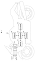
- FIG. 1 is a block diagram showing the configuration of the vehicle posture estimation system of this embodiment.
- the vehicle 100 includes an image pickup unit 101, an image processing unit 102, an object recognition unit 103, a vehicle control unit 104, and an alarm notification unit 105.
- a traveling system control unit 106 is provided.
- the image pickup unit 101 is connected to two cameras, a left camera 11 and a right camera 12, captures an image of the outside world of the vehicle 100, and transfers the captured image to the image processing unit 102.
- FIG. 1 shows an example in which the cameras 11 and 12 are installed in the front part of the vehicle 100 and capture an image in front of the vehicle 100, but the cameras 11 and 12 are installed in the rear part of the vehicle 100 to capture an image in the rear. It may be imaged, or it may be installed in both the front part and the rear part of the vehicle 100 to capture the front and rear images.
- the image processing unit 102 generates an image to be used in the recognition process based on the images captured by the cameras 11 and 12 and the image pickup unit 101, and transfers information about the image to the object recognition unit 103.
- the object recognition unit 103 identifies a traveling lane, a target vehicle, a road sign, a pedestrian, etc. based on the information related to the image information transferred from the image processing unit 102, and transfers the information related to the object recognition to the vehicle control unit 104. do.
- the vehicle control unit 104 acquires various information (such as the traveling speed of the vehicle 100 and the operating state of the brake) from the image processing unit 102, the object recognition unit 103, the alarm notification unit 105, and the traveling system control unit 106, and obtains the acquired information. Compare with preset information such as maximum tilt angle and maximum vehicle speed. Then, appropriate operation information (alarm notification, display, control, etc.) is provided to each unit of the image processing unit 102, the object recognition unit 103, the alarm notification unit 105, and the traveling system control unit 106.
- various information such as the traveling speed of the vehicle 100 and the operating state of the brake
- the vehicle control unit 104 transfers warning information to the warning notification unit 105 based on the captured image and information related to vehicle running, and also transfers the steering angle, deceleration amount, etc. related to braking of the vehicle 100 to the traveling system control unit 106. Transfer to.
- the warning notification unit 105 receives a warning related to the running state of the vehicle 100 from the vehicle control unit 104, and alerts the driver by displaying an image on a liquid crystal panel or the like, or oscillating a voice or a warning sound by a speaker or the like.
- the traveling system control unit 106 performs brake braking and the like based on the information on the deceleration amount related to the traveling state of the vehicle 100 transferred from the vehicle control unit 104.
- the above configuration is an example of the present invention, and the configuration of the present invention is not limited to the above configuration.
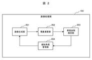
- FIG. 2 is a block diagram showing the configuration of the image processing unit 102 of FIG.
- the image processing unit 102 includes an image generation unit 201, a parallax calculation unit 202, a vehicle posture estimation unit 203, and an inclination angle management unit 204.
- the image generation unit 201 cuts out an image after noise removal, distortion correction, rotation processing, etc. of the image captured by the left camera 11, the right camera 12, and the imaging unit 101, and the edge image used in the recognition processing.
- a shade image is generated and stored in a generated image holding unit of a memory (not shown).
- Other images are not particularly limited as long as they are images necessary for recognition processing.
- parallax calculation unit 202 two images are taken by the left camera 11, the right camera 12, and the image pickup unit 101 based on the image data after the image generation unit 201 performs noise removal, distortion correction, rotation processing, and the like.
- the parallax of the image captured by the camera is obtained, and the parallax is converted into a distance.
- the vehicle posture estimation unit 203 generates a parallax image.
- the vehicle inclination angle is estimated at a predetermined distance on the running road surface from the distance data of the parallax image.
- the tilt angle management unit 204 associates the vehicle tilt angle obtained by the vehicle posture estimation unit 203 with the images captured by the cameras 11 and 12, rotates the captured image using the tilt roll angle, and tilts the pitch. The process of cutting out the captured image using the corners is performed. Then, the image generation unit 201 generates an image to be input to the object recognition unit 103 using the corrected captured image.
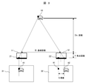
- FIG. 3 conceptually shows the parallax calculation process in the parallax calculation unit 202 of FIG.
- the image of the measurement object 10 is captured by the left camera 11 and the right camera 12.
- the left image 31 of the measurement object 10 is imaged by the two-dimensional sensor 21 of the left camera 11, and the right image 32 of the measurement object 10 is imaged by the two-dimensional sensor 22 of the right camera 12.
- the right image 32 taken by the right camera 12 is used as a reference image, and a reference block image 42 such as 5 pixels ⁇ 5 pixels is defined.
- the size of the block image is not limited to this example.
- the reference image 41 having a search width (for example, 128 pixels) is referenced from the same vertical position (Y coordinate) and horizontal position (X coordinate) as the reference block image 42. select. After that, the difference between the reference block image 42 and the reference image 41 is calculated.
- SAD Sud of Absolute Difference
- I is an image block in the reference image 41 (example: 5 ⁇ 5 pixels)
- T is the image data of the reference block image 42
- i and j are the coordinates in the image block.
- the reference position of the reference image 41 is shifted by one pixel, and the calculation is performed by the search width to search for the position where the SAD value is the smallest.
- the image is taken at the position of the reference image 41.
- a parallax S occurs between the position of the reference block image 42 and the reference image 41.
- the parallax S has a large value when the vehicle in front of the measurement target 10 is close to the left camera 11 and the right camera 12, and a small value when the vehicle is far away.
- the parallax S thus obtained is obtained for the entire image.
- the distance between the left camera 11 and the right camera 12 can be measured by the principle of triangulation.
- a baseline distance of B (m) a baseline distance of B (m), and a focal length of f (pixels)
- the distance Ds from the parallax S can be obtained by the following equation (2).
- FIG. 4 is a diagram showing the principle of calculating the inclination angle (roll angle ⁇ ) of the vehicle 100.
- a roll angle ⁇ is generated.
- the disparity data of the left camera 11 and the right camera 12 mounted on the vehicle 100 in the roll direction in which the center of gravity moves to the left and right detects the distance to the front road surface due to the rotation in the roll direction, and the vehicle roll angle ( ⁇ ) is obtained from the detected distance. ) Is calculated and output.
- FIG. 5 is a flowchart showing processing by the vehicle posture estimation unit 203 of FIG.
- the detection area is set in step S502
- the distance is calculated from the area set in step S502 in step S503
- the detection area of each detection area is calculated in step S504. Performs the process of estimating the tilt angle using the distance.
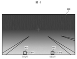
- FIG. 6 shows an example of the detection area set in the parallax image 600.
- step S501 the parallax image calculated by the parallax calculation unit 202 of the image processing unit 102 is acquired.
- the parallax image 600 in FIG. 6 is an image in which the distance information to the measurement object 10 is visualized by the shade of color. In the parallax image, those with a short distance are shown in white, and those with a long distance are shown in black.
- a detection area is set in the parallax image 600.
- the first region 601 and the second region 602 provided on the same horizontal line (the same Y coordinate) are installed in the region corresponding to the road surface. Since the first region 601 and the second region 602 are regions for measuring the distance to each road surface, it is desirable to set them on a short-distance road surface.
- the vertical and horizontal sizes of the first area 601 and the second area 602 it is necessary to set the vertical and horizontal sizes of the first area 601 and the second area 602 to be the same size. If the sizes of the first region 601 and the second region 602 are made too small (for example, one pixel), the accuracy in calculating the distance may deteriorate. Therefore, in this embodiment, a detection area such as 9 pixels in the vertical direction and 9 pixels in the horizontal direction is defined, the center coordinate 611 of the first area 601 is (x1, y1), and the center coordinate 612 of the second area 602 is (x2, y1). ). The size of the detection area may be appropriately changed without departing from the spirit of the present invention.
- step S503 a process of calculating the distance to the road surface reflected in each of the first region 601 and the second region 602 is performed.
- the distance to the road surface is the average value of the distances in each detection area.
- the parallax data in the detection area are arranged in the order of the closest distance, and the average value of the distance is calculated from the data of the shortest distance and the data excluding the data of the farthest distance. Then, the calculation result is used as the representative distance of the detection area.
- the method for calculating the detection distance is not limited to this, and a distance calculation method within the detection region may be adopted based on the standard deviation or the like.
- step S504 the inclination angle is calculated (estimated) using the distances to the respective road surfaces in the first region 601 and the second region 602. The process in step S504 will be described in detail with reference to FIG. 7.
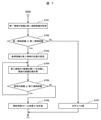
- FIG. 7 is a flowchart showing the details of the step S504 inclination angle calculation process of FIG.
- step S701 the distance calculated from the first region 601 and the second region 602 is acquired.
- step S702 the acquired first area distance and the second area distance are compared, and it is determined whether they are the same value. If both values are the same (No), the vehicle is in a horizontal state with respect to the traveling direction of the vehicle 100. Therefore, the process proceeds to step S707, and the roll angle of the inclination angle of 0 degrees is used as the output of step S504.
- the vehicle 100 will be tilted to the left or right with respect to the traveling direction. For example, when the distance calculated from the first region 601 is larger than the distance calculated from the second region 602, the vehicle 100 is tilted to the right.
- the process proceeds to step S703, the one with the larger distance in the detection area is set as the reference value (reference distance), and the third has the same center coordinates and the same size as the detection area with the smaller distance. Set the area.
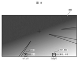
- FIG. 8 is an example showing a case where the detection distance of the first region 801 is larger than the detection distance of the second region 802 in the parallax image 800.
- the detection distance of the first region 801 is set as a reference value
- the vertical and horizontal sizes of the third region 803 are set to the same size as the second region 802
- the center coordinates 813 of the third region 803 are set to the center coordinates of the second region 802. Place it at the same position (x2, y1) as 812.
- step S704 the position coordinates of the third region 803 are shifted by one pixel in the direction directly above the second region 802, and the distance of the third region 803 is calculated again.
- step S705 the process proceeds to step S705, and the reference distance (detection distance of the first region 801) and the distance of the third region 803 are compared.
- the process returns to step S704 and the process of step S704 is repeated. It should be noted that the size to be shifted in the upward direction may be appropriately changed without departing from the spirit of the present invention.
- the process proceeds to step S706, and as shown in FIG. 9, in the disparity image 900, the first region Using the center coordinates 911 (x1, y1) of 901, the center coordinates 912 (x2, y1) of the second region 902, and the center coordinates 913 (x2, y2) of the third region 903, each is according to the following equation (3).
- the tilt angle (roll angle ⁇ ) of the vehicle 100 is calculated from the center coordinates.
- ⁇ x x2-x1
- ⁇ y y2-y1.
- the tilt angle management unit 204 associates the vehicle tilt angle (roll angle ⁇ ) obtained by the vehicle attitude estimation unit 203 with the images taken by the cameras 11 and 12, and uses the tilt roll angle to rotate the image for imaging. Perform processing.
- the image processing unit 102 transfers the vehicle inclination information (roll angle ⁇ ) to the object recognition unit 103, corrects the positions of the recognition world coordinate system, camera coordinate system, image coordinate system, SfM (Structure from Motion), and the like. Perform more accurate recognition.
- the tilt angle of the vehicle 100, the maximum tilt angle with respect to the traveling path, and the maximum vehicle speed are preset, and the vehicle control unit 104 determines the tilt angle of the vehicle 100 together with the transferred vehicle tilt information (roll angle ⁇ ). It performs processing such as notifying the driver of a dangerous inclination angle and controlling the speed of the vehicle 100.
- the tilt angle (roll angle ⁇ ) of the vehicle can be accurately estimated regardless of the driving environment, so that the correction is realized based on appropriate recognition processing. can do.
- the image generation unit 201 can perform a process of rotating the captured image by using the tilt angle.
- the distance to the road surface is measured by using the rear camera installed in the vehicle 100. May be configured to measure and generate vehicle tilt angle information.
- the vehicle posture estimation system of this embodiment is located in the measurement area (parallax image 600) corresponding to the road surface acquired by the distance measuring devices (cameras 11 and 12 and the imaging unit 101) mounted on the vehicle 100.
- An area setting unit (step S502 of the vehicle posture estimation unit 203) for setting one area 601 and a second area 602 on the same horizontal line as the first area 601 and a first area from the vehicle 100.
- the distance calculation unit (step S503 of the vehicle posture estimation unit 203) that calculates the distances to the respective road surfaces of the first region 601 and the second region 602, and the distances to the respective road surfaces of the first region 601 and the second region 602.
- step S504 of the vehicle attitude estimation unit 203 for obtaining the inclination angle (roll angle ⁇ ) of the vehicle 100 based on the positional relationship between the first region 601 and the second region 602. ing.
- step S504 of the vehicle attitude estimation unit 203 as a third region 903 that is not on the same horizontal line as the first region 901 and the second region 902. Search for regions that have the same distance as the first region 901 or the second region 902.
- the distance calculation unit obtains the distance from the image (parallax image 900) obtained by the image pickup apparatus (cameras 11 and 12 and the image pickup unit 101) to the road surface, and determines the area setting unit.
- Step S502 of the vehicle attitude estimation unit 203) sets the first region 901, the second region 902, and the third region 903 that is not on the horizontal line in the image (parallax image 900).
- the third region 903 is a region having a different distance from the first region 901 and the second region 902.
- This embodiment is an example of estimating the pitch angle of the vehicle 100 in the tilt angle processing. It should be noted that duplicate explanations will be omitted for the common points with the first embodiment.
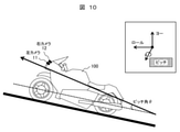
- FIG. 10 is a diagram showing the principle of calculating the vehicle pitch angle.
- the thick broken line in the figure is the front-rear axis of the vehicle 100.
- the front-rear axis roughly coincides with the traveling direction of the vehicle 100, but since it is set based on the vehicle body 100, it does not exactly coincide. For example, when the vehicle is traveling with the front portion of the vehicle 100 slightly raised, the traveling direction of the vehicle 100 and the front-rear axis do not coincide with each other.
- the pitch angle ( ⁇ ) is formed by the tip side (front part of the vehicle 100) of this front-rear axis moving up and down along the direction of gravity. Then, the parallax data of the left camera 11 and the right camera 12 mounted on the front part of the vehicle 100 detects the distance to the front road surface due to the rotation in the pitch direction, and the vehicle pitch angle ( ⁇ ) is calculated from the detected distance. And output.
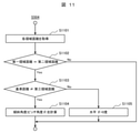
- FIG. 11 shows a flowchart of the tilt angle calculation process for calculating the vehicle pitch angle ( ⁇ ) in this embodiment.
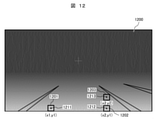
- the position of the third region 1203 is fixed and set on the road surface above the second region 1202.
- the specific position coordinates are not limited, if it is too close to or too far from the second region 1202, the accuracy of calculation may deteriorate. Therefore, it is desirable to set the third region 1203 on the road surface about 1 to 2 m away from the second region 1202.
- each region of the first region 1201, the second region 1202, and the third region 1203 and the center coordinates (1211-1213) are set, and the first The distance calculated from the region 1201 and the second region 1202 is the same value, and when the pitch angle is 0 degrees, the measured value of the third region 1203 is set in advance as the reference distance.
- step S1101 of FIG. 11 the process of acquiring each area distance is a process of acquiring the distance to the road surface reflected in each of the set areas of the first area 1201, the second area 1202, and the third area 1203. ..
- step S1102 the acquired distance of the first region 1201 and the distance of the second region 1202 are compared, and it is determined whether they are the same value. If the two are different (No), it is read from the previously obtained result and used as the pitch angle.
- step S1103 the detection distance and the reference distance of the third region 1203 are compared.
- step S1104 the process proceeds to step S1104, and the inclination angle (pitch angle ⁇ ) is calculated.
- the measured value of the third region 1203 is m3, and the reference distance preset from the distance of the third region 1203 is s3.
- the distance m3 calculated from the third region 1203 is larger than the reference distance s3 (m3> s3), the vehicle 100 is traveling with the front portion slightly raised.
- the distance m3 calculated from the third region 1203 is smaller than the reference distance s3 (m3 ⁇ s3), the front part of the vehicle is lowered.
- the inclination angle (pitch angle ⁇ ) of the vehicle 100 can be calculated by the following equation (4) using the reference distance s3 preset from the measured value m3 of the third region 1203 and the distance of the third region 1203. Yes (step S1104).
- the tilt angle information calculated in step S504 shown in FIG. 11 is transferred to each part.
- the tilt angle management unit 204 associates the vehicle tilt angle (pitch angle ⁇ ) obtained by the vehicle attitude estimation unit 203 with the images taken by the cameras 11 and 12, and cuts out the captured image using the tilt pitch angle. Perform processing.
- Vehicle tilt information (pitch angle ⁇ ) is transferred to the object recognition unit 103, and the positions of the recognition world coordinate system, camera coordinate system, image coordinate system, SfM (Structure from Motion), etc. are corrected for more accurate recognition. conduct.
- the tilt angle of the vehicle 100, the maximum tilt angle with respect to the traveling path, and the maximum vehicle speed are preset, and the vehicle control unit 104 determines the tilt angle together with the transferred vehicle tilt information (pitch angle ⁇ ). It performs processing such as notifying the driver of a dangerous inclination angle and controlling the speed of the vehicle 100.
- the tilt angle (pitch angle ⁇ ) of the vehicle can be accurately estimated regardless of the driving environment, so that the correction is realized based on appropriate recognition processing. can do.
- the image generation unit 201 can perform a process of rotating the captured image using the tilt angle.
- the rear camera installed in the vehicle 100 may be used to measure the distance to the road surface and generate vehicle inclination angle information.
- This embodiment differs from the first and second embodiments in that the radius of curvature of the road is used when determining the vehicle inclination angle. It should be noted that overlapping description of common points with the first and second embodiments will be omitted.
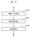
- FIG. 13 shows a flowchart of the vehicle inclination angle calculation process in this embodiment.
- step S1301 the parallax data generated by the parallax calculation unit 202 is acquired.
- step S1302 the radius of curvature of the road is calculated.
- step S1303 the vehicle inclination angle is obtained from the radius of curvature of the road calculated in step S1302 and the own vehicle speed.
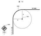
- the radius of curvature 1401 of the curve can be obtained based on the parallax data.
- the inclination angle (roll angle ⁇ ) of the vehicle can be calculated from the curve curvature radius (R) 1401 calculated from the parallax data, the vehicle speed v, and the gravitational acceleration g by the following equation (5). can.
- the present invention is not limited to the above-described embodiment, but includes various modifications.
- the above embodiments have been described in detail to aid in understanding of the present invention and are not necessarily limited to those comprising all of the described configurations.
- it is possible to replace a part of the configuration of one embodiment with the configuration of another embodiment and it is also possible to add the configuration of another embodiment to the configuration of one embodiment.
- the difficulty of finding infringement of the present invention may be verified by the difference between the case where the plane image is transferred and the actual image from the viewpoint of the parallax image.
- the vehicle 100 has been described mainly by using an example of a motorcycle, but the present invention also applies to an off-road four-wheeled vehicle or the like, which is premised on a large inclination of the vehicle body from front to back and left and right. It is valid.
- the present invention is ADAS (Advanced) that alerts the driver by displaying warning information based on the estimated (calculated) tilt angle by an image display by a liquid crystal panel or the like, or by oscillating a voice or a warning sound by a speaker or the like. It can be applied to Driver Assistance Systems), and further, the warning information based on the estimated (calculated) tilt angle is transferred to the warning notification unit 105, and the automatic operation AD (automatic driving AD) is transferred to the traveling system control unit 106. It can also be applied to Autonomous Driving).
- Detection area 611,612,811,812 , 815, 911, 912, 913, 121, 121, 1213 ... Center coordinates (of the detection area), 1400 ... Travel path, 1401 ... Curve radius of curvature, 1402 ... Road sign
Landscapes
- Engineering & Computer Science (AREA)
- Physics & Mathematics (AREA)
- Mechanical Engineering (AREA)
- Automation & Control Theory (AREA)
- Mathematical Physics (AREA)
- Transportation (AREA)
- General Physics & Mathematics (AREA)
- Theoretical Computer Science (AREA)
- Multimedia (AREA)
- Radar, Positioning & Navigation (AREA)
- Remote Sensing (AREA)
- Image Processing (AREA)
- Image Analysis (AREA)
- Length Measuring Devices By Optical Means (AREA)
- Control Of Driving Devices And Active Controlling Of Vehicle (AREA)
- Traffic Control Systems (AREA)
Abstract
Description
ブロック画像のサイズはこの例に限るものではない。





Claims (12)
- 車両に搭載された測距装置で取得した路面に対応する測定領域内に、第一の領域と、前記第一の領域と同一の水平ライン上の第二の領域と、を設定する領域設定部と、
前記車両から前記第一の領域および前記第二の領域のそれぞれの路面までの距離を算出する距離算出部と、
前記第一の領域および前記第二の領域のそれぞれの路面までの距離、並びに、前記第一の領域および前記第二の領域の位置関係に基づいて、前記車両の傾斜角を求める傾斜角算出部と、
を有する車両姿勢推定システム。 - 請求項1に記載の車両姿勢推定システムにおいて、
前記傾斜角算出部は、前記水平ライン上にない第三の領域として、前記第一の領域または前記第二の領域と同じ距離を持つ領域を探索する車両姿勢推定システム。 - 請求項1に記載の車両姿勢推定システムにおいて、
前記距離算出部は、撮像装置で得られた画像から路面までの距離を求め、
前記領域設定部は、前記第一の領域と前記第二の領域と前記水平ライン上にない第三の領域を前記画像内に設定する車両姿勢推定システム。 - 請求項3に記載の車両姿勢推定システムにおいて、
前記第三の領域は、前記第一の領域および前記第二の領域とは異なる距離の領域である車両姿勢推定システム。 - 請求項1に記載の車両姿勢推定システムにおいて、
前記測距装置は、複数のカメラを有し、
前記距離算出部は、前記複数のカメラで撮影した複数の画像から路面までの距離を算出し、
前記傾斜角算出部は、前記複数のカメラで撮影した複数の画像の視差に基づいて、前記車両の傾斜角を求める車両姿勢推定システム。 - 請求項1に記載の車両姿勢推定システムにおいて、
前記傾斜角算出部は、前記第一の領域および前記第二の領域の位置関係から道路の曲率半径を算出し、
前記算出した道路の曲率半径と前記車両の車速と重力加速度に基づいて、前記車両の傾斜角を求める車両姿勢推定システム。 - 車両に搭載された測距装置で取得した路面に対応する測定領域内に、第一の領域と、前記第一の領域と同一の水平ライン上の第二の領域と、を設定し、
前記車両から前記第一の領域および前記第二の領域のそれぞれの路面までの距離を算出し、
前記第一の領域および前記第二の領域のそれぞれの路面までの距離、並びに、前記第一の領域および前記第二の領域の位置関係に基づいて、前記車両の傾斜角を求める車両姿勢推定方法。 - 請求項7に記載の車両姿勢推定方法において、
前記水平ライン上にない第三の領域として、前記第一の領域または前記第二の領域と同じ距離を持つ領域を探索する車両姿勢推定方法。 - 請求項7に記載の車両姿勢推定方法において、
撮像装置で得られた画像から路面までの距離を求め、
前記第一の領域と前記第二の領域と前記水平ライン上にない第三の領域を前記画像内に設定する車両姿勢推定方法。 - 請求項9に記載の車両姿勢推定方法において、
前記第三の領域は、前記第一の領域および前記第二の領域とは異なる距離の領域である車両姿勢推定方法。 - 請求項7に記載の車両姿勢推定方法において、
複数のカメラで撮影した複数の画像から路面までの距離を算出し、
前記複数のカメラで撮影した複数の画像の視差に基づいて、前記車両の傾斜角を求める車両姿勢推定方法。 - 請求項7に記載の車両姿勢推定方法において、
前記第一の領域および前記第二の領域の位置関係から道路の曲率半径を算出し、
前記算出した道路の曲率半径と前記車両の車速と重力加速度に基づいて、前記車両の傾斜角を求める車両姿勢推定方法。
Priority Applications (4)
| Application Number | Priority Date | Filing Date | Title |
|---|---|---|---|
| JP2022550357A JP7411108B2 (ja) | 2020-09-16 | 2021-06-29 | 車両姿勢推定システムおよび車両姿勢推定方法 |
| US18/025,839 US12304503B2 (en) | 2020-09-16 | 2021-06-29 | Vehicle orientation estimation system and vehicle orientation estimation method |
| CN202180050480.0A CN115943287B (zh) | 2020-09-16 | 2021-06-29 | 车辆姿态推断系统及车辆姿态推断方法 |
| DE112021003735.8T DE112021003735B4 (de) | 2020-09-16 | 2021-06-29 | Fahrzeugorientierungsschätzungssystem und fahrzeugorientierungsschätzungsverfahren |
Applications Claiming Priority (2)
| Application Number | Priority Date | Filing Date | Title |
|---|---|---|---|
| JP2020-155190 | 2020-09-16 | ||
| JP2020155190 | 2020-09-16 |
Publications (1)
| Publication Number | Publication Date |
|---|---|
| WO2022059289A1 true WO2022059289A1 (ja) | 2022-03-24 |
Family
ID=80776067
Family Applications (1)
| Application Number | Title | Priority Date | Filing Date |
|---|---|---|---|
| PCT/JP2021/024521 Ceased WO2022059289A1 (ja) | 2020-09-16 | 2021-06-29 | 車両姿勢推定システムおよび車両姿勢推定方法 |
Country Status (5)
| Country | Link |
|---|---|
| US (1) | US12304503B2 (ja) |
| JP (1) | JP7411108B2 (ja) |
| CN (1) | CN115943287B (ja) |
| DE (1) | DE112021003735B4 (ja) |
| WO (1) | WO2022059289A1 (ja) |
Cited By (1)
| Publication number | Priority date | Publication date | Assignee | Title |
|---|---|---|---|---|
| WO2025158549A1 (ja) * | 2024-01-24 | 2025-07-31 | Astemo株式会社 | 車両制御装置 |
Families Citing this family (1)
| Publication number | Priority date | Publication date | Assignee | Title |
|---|---|---|---|---|
| KR102615479B1 (ko) * | 2021-11-24 | 2023-12-19 | 현대모비스 주식회사 | 램프 및 그것의 동작 방법, 차량 |
Citations (3)
| Publication number | Priority date | Publication date | Assignee | Title |
|---|---|---|---|---|
| JP2015143979A (ja) * | 2013-12-27 | 2015-08-06 | 株式会社リコー | 画像処理装置、画像処理方法、プログラム、画像処理システム |
| JP2018091652A (ja) * | 2016-11-30 | 2018-06-14 | 株式会社リコー | 情報処理装置、撮像装置、機器制御システム、情報処理方法、及びプログラム |
| JP2020087176A (ja) * | 2018-11-29 | 2020-06-04 | 日立オートモティブシステムズ株式会社 | 外界認識装置 |
Family Cites Families (21)
| Publication number | Priority date | Publication date | Assignee | Title |
|---|---|---|---|---|
| JP3341605B2 (ja) * | 1996-12-05 | 2002-11-05 | 日産自動車株式会社 | 車両用画像処理装置 |
| JP3352655B2 (ja) * | 1999-09-22 | 2002-12-03 | 富士重工業株式会社 | 車線認識装置 |
| JP3995846B2 (ja) * | 1999-09-24 | 2007-10-24 | 本田技研工業株式会社 | 物体認識装置 |
| DE19962491A1 (de) | 1999-12-23 | 2001-07-05 | Daimler Chrysler Ag | Verfahren zur optischen Überwachung der Umgebung eines sich bewegenden Fahrzeugs |
| JP4296076B2 (ja) | 2003-11-13 | 2009-07-15 | 三菱電機株式会社 | 走行車線認識装置 |
| DE102004022289A1 (de) | 2004-05-04 | 2005-12-01 | Robert Bosch Gmbh | Fahrdynamikregelung mit Bildsensorsystem |
| DE102004036044A1 (de) | 2004-07-24 | 2006-02-16 | Robert Bosch Gmbh | Anordnung zur Erfassung von Bewegungen eines Fahrzeuges |
| JP2008286648A (ja) * | 2007-05-17 | 2008-11-27 | Sumitomo Electric Ind Ltd | 距離計測装置、距離計測システム、距離計測方法 |
| DE602008005448D1 (de) | 2007-06-27 | 2011-04-21 | Panasonic Corp | Bildgebungsgerät, verfahren, systemintegrierte schaltung und programm |
| DE102012201802A1 (de) | 2012-02-07 | 2013-08-08 | Robert Bosch Gmbh | Fahrerassistenzsystem für ein Zweirad zur Schräglagenwarnung |
| US8494716B1 (en) | 2012-06-04 | 2013-07-23 | GM Global Technology Operations LLC | Lane keeping system using rear camera |
| JP2014089548A (ja) * | 2012-10-30 | 2014-05-15 | Sharp Corp | 路面段差検出方法、路面段差検出装置、路面段差検出装置を備えた車両 |
| JP6274557B2 (ja) * | 2013-02-18 | 2018-02-07 | 株式会社リコー | 移動面情報検出装置、及びこれを用いた移動体機器制御システム並びに移動面情報検出用プログラム |
| JP5947268B2 (ja) | 2013-09-20 | 2016-07-06 | 本田技研工業株式会社 | 車両のロール角推定装置 |
| JP6459659B2 (ja) * | 2014-03-18 | 2019-01-30 | 株式会社リコー | 画像処理装置、画像処理方法、運転支援システム、プログラム |
| JP2015227082A (ja) | 2014-05-30 | 2015-12-17 | 日本電産エレシス株式会社 | 車体傾斜角度検出装置および車体傾斜角度検出方法 |
| JP6492974B2 (ja) * | 2015-05-28 | 2019-04-03 | 日産自動車株式会社 | 自己位置算出装置及び自己位置算出方法 |
| EP3375682B1 (en) | 2015-12-14 | 2020-08-26 | Yamaha Hatsudoki Kabushiki Kaisha | Vehicle-use roll-angle estimation system, vehicle, vehicle-use roll-angle estimation method |
| JP6969738B2 (ja) * | 2017-07-10 | 2021-11-24 | 株式会社Zmp | 物体検出装置及び方法 |
| JP7139597B2 (ja) * | 2017-12-07 | 2022-09-21 | 株式会社豊田中央研究所 | 自己位置誤差推定装置及び自己位置誤差推定方法 |
| WO2020039852A1 (ja) * | 2018-08-23 | 2020-02-27 | ヤマハ発動機株式会社 | リーンビークル用障害物検知装置 |
-
2021
- 2021-06-29 US US18/025,839 patent/US12304503B2/en active Active
- 2021-06-29 JP JP2022550357A patent/JP7411108B2/ja active Active
- 2021-06-29 WO PCT/JP2021/024521 patent/WO2022059289A1/ja not_active Ceased
- 2021-06-29 DE DE112021003735.8T patent/DE112021003735B4/de active Active
- 2021-06-29 CN CN202180050480.0A patent/CN115943287B/zh active Active
Patent Citations (3)
| Publication number | Priority date | Publication date | Assignee | Title |
|---|---|---|---|---|
| JP2015143979A (ja) * | 2013-12-27 | 2015-08-06 | 株式会社リコー | 画像処理装置、画像処理方法、プログラム、画像処理システム |
| JP2018091652A (ja) * | 2016-11-30 | 2018-06-14 | 株式会社リコー | 情報処理装置、撮像装置、機器制御システム、情報処理方法、及びプログラム |
| JP2020087176A (ja) * | 2018-11-29 | 2020-06-04 | 日立オートモティブシステムズ株式会社 | 外界認識装置 |
Cited By (1)
| Publication number | Priority date | Publication date | Assignee | Title |
|---|---|---|---|---|
| WO2025158549A1 (ja) * | 2024-01-24 | 2025-07-31 | Astemo株式会社 | 車両制御装置 |
Also Published As
| Publication number | Publication date |
|---|---|
| US20230347910A1 (en) | 2023-11-02 |
| US12304503B2 (en) | 2025-05-20 |
| JP7411108B2 (ja) | 2024-01-10 |
| CN115943287B (zh) | 2025-08-26 |
| DE112021003735T5 (de) | 2023-06-01 |
| JPWO2022059289A1 (ja) | 2022-03-24 |
| DE112021003735B4 (de) | 2026-07-09 |
| CN115943287A (zh) | 2023-04-07 |
Similar Documents
| Publication | Publication Date | Title |
|---|---|---|
| JP6941070B2 (ja) | ステレオカメラ装置 | |
| US9884623B2 (en) | Method for image-based vehicle localization | |
| JP3776094B2 (ja) | 監視装置、監視方法および監視用プログラム | |
| JP6450294B2 (ja) | 物体検出装置、物体検出方法、及びプログラム | |
| EP2348279B1 (en) | Road measurement device and method for measuring road | |
| JP4676373B2 (ja) | 周辺認識装置、周辺認識方法、プログラム | |
| KR20210017525A (ko) | 거리 추정 장치 및 이의 동작 방법 | |
| EP2743889A2 (en) | Stereoscopic camera object detection system and method of aligning the same | |
| US9594966B2 (en) | Obstacle detection device and obstacle detection method | |
| JP2010072807A (ja) | 道路境界検出判断装置 | |
| JP5421819B2 (ja) | 車線認識装置 | |
| WO2021215199A1 (ja) | 情報処理装置、撮像システム、情報処理方法及びコンピュータプログラム | |
| US20230150533A1 (en) | Vehicle control system and vehicle driving method using the vehicle control system | |
| JP7411108B2 (ja) | 車両姿勢推定システムおよび車両姿勢推定方法 | |
| WO2023090170A1 (ja) | 画像処理装置 | |
| Petrovai et al. | A stereovision based approach for detecting and tracking lane and forward obstacles on mobile devices | |
| US11477371B2 (en) | Partial image generating device, storage medium storing computer program for partial image generation and partial image generating method | |
| WO2020110435A1 (ja) | 外界認識装置 | |
| US20250384698A1 (en) | Vehicle control system and vehicle driving method using the vehicle control system | |
| JP5832850B2 (ja) | 車線監視システム及び車線監視方法 | |
| JP6185327B2 (ja) | 車両後側方警報装置、車両後側方警報方法および他車両距離検出装置 | |
| JP3612821B2 (ja) | 車載用距離測定装置 | |
| JP2007279805A (ja) | 障害物衝突判断装置および障害物衝突警告システム | |
| JP3586938B2 (ja) | 車載用距離測定装置 | |
| JP2024011893A (ja) | 車線判定装置、車線判定方向及び車線判定用コンピュータプログラム |
Legal Events
| Date | Code | Title | Description |
|---|---|---|---|
| 121 | Ep: the epo has been informed by wipo that ep was designated in this application |
Ref document number: 21868976 Country of ref document: EP Kind code of ref document: A1 |
|
| ENP | Entry into the national phase |
Ref document number: 2022550357 Country of ref document: JP Kind code of ref document: A |
|
| WWE | Wipo information: entry into national phase |
Ref document number: 112021003735 Country of ref document: DE |
|
| 122 | Ep: pct application non-entry in european phase |
Ref document number: 21868976 Country of ref document: EP Kind code of ref document: A1 |
|
| WWG | Wipo information: grant in national office |
Ref document number: 18025839 Country of ref document: US |
|
| WWG | Wipo information: grant in national office |
Ref document number: 202180050480.0 Country of ref document: CN |
|
| WWG | Wipo information: grant in national office |
Ref document number: 112021003735 Country of ref document: DE |