WO2022054845A1 - 空気調和装置 - Google Patents
空気調和装置 Download PDFInfo
- Publication number
- WO2022054845A1 WO2022054845A1 PCT/JP2021/033047 JP2021033047W WO2022054845A1 WO 2022054845 A1 WO2022054845 A1 WO 2022054845A1 JP 2021033047 W JP2021033047 W JP 2021033047W WO 2022054845 A1 WO2022054845 A1 WO 2022054845A1
- Authority
- WO
- WIPO (PCT)
- Prior art keywords
- temperature
- heat exchanger
- air
- indoor
- air conditioner
- Prior art date
- Legal status (The legal status is an assumption and is not a legal conclusion. Google has not performed a legal analysis and makes no representation as to the accuracy of the status listed.)
- Ceased
Links
Images




Classifications
-
- F—MECHANICAL ENGINEERING; LIGHTING; HEATING; WEAPONS; BLASTING
- F24—HEATING; RANGES; VENTILATING
- F24F—AIR-CONDITIONING; AIR-HUMIDIFICATION; VENTILATION; USE OF AIR CURRENTS FOR SCREENING
- F24F11/00—Control or safety arrangements
- F24F11/30—Control or safety arrangements for purposes related to the operation of the system, e.g. for safety or monitoring
- F24F11/49—Control or safety arrangements for purposes related to the operation of the system, e.g. for safety or monitoring ensuring correct operation, e.g. by trial operation or configuration checks
-
- F—MECHANICAL ENGINEERING; LIGHTING; HEATING; WEAPONS; BLASTING
- F24—HEATING; RANGES; VENTILATING
- F24F—AIR-CONDITIONING; AIR-HUMIDIFICATION; VENTILATION; USE OF AIR CURRENTS FOR SCREENING
- F24F11/00—Control or safety arrangements
- F24F11/62—Control or safety arrangements characterised by the type of control or by internal processing, e.g. using fuzzy logic, adaptive control or estimation of values
- F24F11/63—Electronic processing
- F24F11/65—Electronic processing for selecting an operating mode
-
- F—MECHANICAL ENGINEERING; LIGHTING; HEATING; WEAPONS; BLASTING
- F24—HEATING; RANGES; VENTILATING
- F24F—AIR-CONDITIONING; AIR-HUMIDIFICATION; VENTILATION; USE OF AIR CURRENTS FOR SCREENING
- F24F11/00—Control or safety arrangements
- F24F11/70—Control systems characterised by their outputs; Constructional details thereof
-
- F—MECHANICAL ENGINEERING; LIGHTING; HEATING; WEAPONS; BLASTING
- F24—HEATING; RANGES; VENTILATING
- F24F—AIR-CONDITIONING; AIR-HUMIDIFICATION; VENTILATION; USE OF AIR CURRENTS FOR SCREENING
- F24F11/00—Control or safety arrangements
- F24F11/70—Control systems characterised by their outputs; Constructional details thereof
- F24F11/80—Control systems characterised by their outputs; Constructional details thereof for controlling the temperature of the supplied air
- F24F11/86—Control systems characterised by their outputs; Constructional details thereof for controlling the temperature of the supplied air by controlling compressors within refrigeration or heat pump circuits
Definitions
- This disclosure relates to an air conditioner.
- Patent Document 1 discloses an air conditioner that performs a cleaning operation for cleaning the surface of an indoor heat exchanger.
- the indoor heat exchanger functions as an evaporator in the cleaning operation, and the evaporation temperature of the refrigerant flowing through the indoor heat exchanger is set to the dew point temperature or lower. This causes condensation on the surface of the indoor heat exchanger.
- the purpose of the present disclosure is to preferably remove dirt adhering to the surface of the heat exchanger with dew condensation water.
- the first aspect of the present disclosure is intended for an air conditioner (1).
- the air conditioner (1) includes a refrigerant circuit (21) including a heat exchanger (25, 31) that exchanges heat with air, and a control device (9) that controls the operation of the refrigerant circuit (21). ..
- the refrigerant circuit (21) is configured so that the functions of the heat exchangers (25, 31) can be switched between an evaporator and a radiator.
- the surface of the heat exchanger (25, 31) is provided with a temperature-responsive material (65) that becomes hydrophilic at a temperature lower than a predetermined transition point and becomes hydrophobic at a temperature higher than the transition point.
- the term "hydrophobicity" as used herein is a concept including so-called water repellency.
- the control device (9) makes the heat exchanger (25, 31) function as an evaporator and executes a first operation of cooling the temperature of the temperature-responsive material (65) to a temperature lower than the transition point. After that, the heat exchanger (25, 31) is made to function as a radiator, and a second operation of heating the temperature of the temperature-responsive material (65) to a temperature higher than the transition point is executed.
- the temperature of the temperature-responsive material (65) becomes lower than the transition point, and the temperature-responsive material (65) becomes hydrophilic.
- the hydrophilic temperature-responsive material (65) can store moisture in the air that condenses on the surface of the heat exchanger (25, 31) as an evaporator.
- the temperature of the temperature-responsive material (65) becomes higher than the transition point, and the temperature-responsive material (65) becomes hydrophobic.
- the hydrophobic temperature-responsive material (65) causes the dew condensation water or ice accumulated in the first operation to flow downward by its own weight. As a result, dirt adhering to the surface of the heat exchanger (25, 31) can be suitably removed.
- the second aspect of the present disclosure is the air conditioner (1) provided with the indoor unit (3) provided with the heat exchanger (31) in the air conditioner (1) of the first aspect.
- the indoor unit (3) has a blower (49) that takes in indoor air and passes it through the heat exchanger (31). In the second operation, when the temperature of the air in the room is higher than the transition point, the heat exchanger (31) is stopped and the blower (49) is operated.
- the blower (49) is operated to heat the indoor air to the heat exchanger (31). Heats the temperature responsive material (65) to a temperature higher than the transition point. At this time, since the heat exchanger (31) is stopped, energy saving can be achieved as compared with the case where the heat exchanger (31) functions as a radiator. In addition, it is possible to prevent the temperature of the air in the room from rising and prevent people in the room from feeling uncomfortable.
- a third aspect of the present disclosure is the air conditioner (1) of the first or second aspect, wherein the control device (9) performs the second operation within 15 minutes after the first operation is completed. It is an air conditioner (1) that starts.
- the second operation is started within 15 minutes after the first operation is completed. According to this, the second operation is started before the dew condensation water or ice accumulated in the temperature-responsive material (65) gradually flows down with the passage of time and decreases by the first operation. Thereby, in the second operation, the amount of condensed water or ice flowing on the surface of the heat exchanger (25, 31) is secured.
- a fourth aspect of the present disclosure is that in the air conditioner (1) of any one of the first to third aspects, in the first operation, the temperature-responsive material (65) is cooled to the dew point temperature or lower. , Air conditioner (1).
- the temperature-responsive material (65) in the first operation, is cooled to the dew point temperature or lower. Moisture in the air condenses on the temperature-responsive material (65) that has been cooled and becomes hydrophilic in this way, and the dew condensation water can be positively accumulated.
- a fifth aspect of the present disclosure is an air conditioner (1) including an indoor unit (3) provided with the heat exchanger (31) in the air conditioner (1) of the fourth aspect.
- the indoor unit (3) has a blower (49) that supplies air that has passed through the heat exchanger (31) into the room.
- the control device (9) operates the blower (49) and functions the heat exchanger (31) as an evaporator to execute a cooling operation for cooling the air in the room as the first operation. When the cooling operation is completed, the second operation is started.
- the second operation is started when the cooling operation is completed.
- the cooling operation when moisture in the air condenses on the surface of the heat exchanger (31) as a condenser, the dew condensation water collects on the hydrophilic temperature-responsive material (65). Since the first operation is not executed separately from this cooling operation, energy saving can be achieved as compared with the case where the first operation is executed even after the cooling operation.
- a sixth aspect of the present disclosure is the air conditioner (1) of the fourth aspect, in which the temperature responsive material (65) is cooled below the freezing point in the first operation. ..
- the temperature-responsive material (65) in the first operation, is cooled below the freezing point. Moisture in the air condenses and freezes on the temperature-responsive material (65) that has become hydrophilic after being cooled in this way, and the dew condensation water can be positively stored as ice.
- the temperature-responsive material (65) is heated, so that the ice accumulated in the temperature-responsive material (65) in the first operation is melted. Then, when the temperature-responsive material (65) exhibits hydrophobicity, ice peels off from the surface of the indoor heat exchanger (25, 31) or becomes water, which is used in the indoor heat exchanger (25, 31). Flow down the surface.
- a seventh aspect of the present disclosure further comprises a humidifier (7) that humidifies the air passing through the heat exchanger (31) in the air conditioner (1) of any one of the first to sixth aspects. It is an air conditioner (1) provided.
- the heat exchanger (31) is provided in the indoor unit (3).
- the control device (9) operates the humidifier (7) before executing the first operation.
- the air in the room is humidified by operating the humidifier (7).
- the dew point temperature at which dew condensation occurs on the temperature-responsive material (65) provided in the heat exchanger (31) of the indoor unit (3) rises.
- dew condensation water can be generated in the hydrophilic temperature-responsive material (65).
- FIG. 1 is a schematic diagram illustrating the configuration of an air conditioner.
- FIG. 2 is an overall configuration diagram including a refrigerant circuit and an air flow path of the air conditioner.
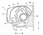
- FIG. 3 is a cross-sectional view illustrating the configuration of the indoor unit.
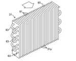
- FIG. 4 is a perspective view illustrating the configuration of the indoor heat exchanger.
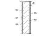
- FIG. 5 is a cross-sectional view illustrating the fins of the indoor heat exchanger.
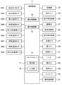
- FIG. 6 is a block diagram showing a control device of an air conditioner and a device connected to the control device.
- FIG. 7 is a flowchart relating to the second operation of the air conditioner.
- FIG. 8 is a flowchart relating to the second operation of the air conditioner.
- the air conditioner (1) is a device that regulates the temperature and humidity of the air in the target space.
- the target space of this example is an indoor space.
- the air conditioner (1) is a pair type air conditioner having one indoor unit (3) and one outdoor unit (5). As shown in FIGS. 1 and 2, the air conditioner (1) includes an indoor unit (3), an outdoor unit (5), a humidifier (7), and a control device (9).
- the indoor unit (3) and the humidifier (7) are connected via a hose (11).
- the indoor unit (3) and the outdoor unit (5) are connected to each other via a liquid connecting pipe (13) and a gas connecting pipe (15).
- the liquid connecting pipe (13) and the gas connecting pipe (15) are connected to the piping joint (17) provided in the indoor unit (3) and the closing valve (19) provided in the outdoor unit (5), respectively.
- the indoor unit (3), outdoor unit (5), liquid communication pipe (13) and gas communication pipe (15) constitute the refrigerant circuit (21).
- Refrigerant circulates in the refrigerant circuit (21).
- the refrigerant in this example is difluoromethane.
- the refrigerant circuit (21) performs a steam compression type refrigeration cycle.
- the refrigerant circuit (21) mainly has a compressor (23), an outdoor heat exchanger (25), an expansion valve (27), a four-way switching valve (29), and an indoor heat exchanger (31). ..
- the refrigerant circuit (21) is configured so that the function of the indoor heat exchanger (31) can be switched between an evaporator and a radiator. Specifically, the refrigerant circuit (21) performs a first refrigeration cycle and a second refrigeration cycle according to the switching of the four-way switching valve (29).
- the first refrigeration cycle is a refrigeration cycle using the indoor heat exchanger (31) as an evaporator.
- the second refrigeration cycle is a refrigeration cycle using the indoor heat exchanger (31) as a radiator.
- the outdoor unit (5) is installed outdoors.
- the outdoor unit (5) includes a casing (22), a compressor (23), an outdoor fan (24), an outdoor heat exchanger (25), an expansion valve (27), and a four-way switching valve (29).
- the outdoor heat exchanger (25) is provided in the outdoor unit (5).
- the casing (22) houses the compressor (23), outdoor fan (24), outdoor heat exchanger (25), expansion valve (27) and four-way switching valve (29).
- a suction port (22i) and an outlet (22o) are formed in the casing (22).
- the suction port (22i) is located behind the casing (22).
- the suction port (22i) is an opening for sucking outdoor air.
- the outlet (22o) is located on the front side of the casing (22).
- the air outlet (22o) is an opening for blowing out the air after heat exchange.
- an air passage (22p) is provided from the suction port (22i) to the air outlet (22o).
- the compressor (23) sucks in low-pressure gas refrigerant and compresses it.
- the compressor (23) discharges the refrigerant compressed by the drive of the motor (23 m).
- the compressor (23) is a variable displacement compressor in which electric power is supplied from an inverter circuit to a motor (23 m).
- the compressor (23) is configured so that the operating capacity can be changed by adjusting the operating frequency (rotational speed) of the motor (23 m).
- the outdoor fan (24) is located in the air passage (22p).
- the outdoor fan (24) is rotated by the drive of a motor (24 m).
- the air conveyed by the outdoor fan (24) is sucked into the casing (22) from the suction port (22i), flows through the air passage (22p), and is blown out from the outlet (22o) to the outside of the casing (22).
- the outdoor fan (24) conveys the outdoor air so that it passes through the outdoor heat exchanger (25).
- the outdoor heat exchanger (25) is located on the upstream side of the outdoor fan (24) in the air passage (22p).
- the outdoor heat exchanger (25) is an example of a heat source heat exchanger that supplies heat energy to the indoor heat exchanger (31).
- the outdoor heat exchanger (25) exchanges heat with the outdoor air carried by the outdoor fan (24). Strictly speaking, the outdoor heat exchanger (25) exchanges heat between the outdoor air carried by the outdoor fan (24) and the internal refrigerant.
- the expansion valve (27) is an example of a pressure reducing mechanism.
- the expansion valve (27) depressurizes the refrigerant.
- the expansion valve (27) is an electric expansion valve whose opening degree can be adjusted.
- the depressurizing mechanism may be a temperature-sensitive expansion valve, an expander, a capillary tube, or the like.
- the expansion valve (27) may be connected to the liquid line of the refrigerant circuit (21) and may be provided in the indoor unit (3).
- the four-way switching valve (29) has a first port (P1), a second port (P2), a third port (P3), and a fourth port (P4).
- the first port (P1) is connected to the discharge portion of the compressor (23).
- the second port (P2) is connected to the suction part of the compressor (23).
- the third port (P3) is connected to the gas end of the outdoor heat exchanger (25).
- the fourth port (P4) is connected to the gas connecting pipe (15).
- the four-way switching valve (29) is switched between the first state (the state shown by the solid line in FIG. 2) and the second state (the state shown by the broken line in FIG. 2).
- the four-way switching valve (29) in the first state communicates the first port (P1) and the third port (P3), and communicates the second port (P2) and the fourth port (P4).
- the four-way switching valve (29) in the second state communicates the first port (P1) and the fourth port (P4), and communicates the second port (P2) and the third port (P3).
- the outdoor unit (5) is provided with an outdoor control unit (33) constituting the control device (9) and various sensors. Various sensors are connected to the outdoor control unit (33). The sensor outputs a detection signal to the outdoor control unit (33).
- the sensor includes a discharge pressure sensor (SN1), a discharge temperature sensor (SN2), a suction temperature sensor (SN3), an outside air temperature sensor (SN4), and a first refrigerant temperature sensor (SN5).
- the discharge pressure sensor (SN1) detects the pressure of the high-pressure refrigerant discharged from the compressor (23).
- the discharge temperature sensor (SN2) detects the temperature of the high-pressure refrigerant discharged from the compressor (23).
- the suction temperature sensor (SN3) detects the temperature of the low pressure refrigerant sucked into the compressor (23).
- the outside air temperature sensor (SN4) detects the temperature of the outdoor air.
- the first refrigerant temperature sensor (SN5) detects the temperature of the refrigerant inside the outdoor heat exchanger (25).
- the humidifier (7) is installed outdoors.
- the humidifier (7) of this example is integrated with the outdoor unit (5).
- the humidifier (7) is a device that takes in moisture from the outdoor air to generate high-humidity air and sends the high-humidity air to the indoor unit (3).
- the humidifier (7) has a casing (35), a humidifying rotor (37), a first fan (39), a switching damper (41), a heater (43), and a second fan (45). ..
- the casing (35) is attached to the casing (22) of the outdoor unit (5).
- the casing (35) houses the humidifying rotor (37), the first fan (39), the switching damper (41), the heater (43) and the second fan (45).
- the casing (35) is formed with a suction port (35i), an exhaust port (35o), and an intake / exhaust port (35a).
- the suction port (35i) and the suction port (35a) are arranged on the rear side of the casing (35).
- the exhaust port (35o) is located on the front side of the casing (35).
- the suction port (35i) is an opening for sucking in outdoor air for moisture absorption.
- the exhaust port (35o) is an opening for exhausting air after absorbing moisture.
- the suction / exhaust port (35a) is an opening for sucking in outdoor air or discharging air sent from the room.
- a second passage (35q) that follows.
- the humidifying rotor (37) is arranged over the first passage (35p) and the second passage (35q).
- the humidifying rotor (37) is, for example, a disk-shaped ceramic rotor having a honeycomb structure.
- the humidifying rotor (37) is made of an adsorbent such as silica gel, zeolite, and alumina.
- the adsorbent has the property of adsorbing moisture in the air that comes into contact with it.
- the hygroscopic agent further has the property of desorbing adsorbed moisture when heated.
- the humidifying rotor (37) is rotated by the drive of the motor (37m).
- the humidifying rotor (37) has a moisture absorbing region (37a) for adsorbing moisture in the air and a moisture releasing region (37r) for desorbing moisture in the air.
- the moisture absorption region (37a) is composed of a portion of the humidifying rotor (37) located in the first passage (35p).
- the moisture release region (37r) is composed of a portion of the humidifying rotor (37) located in the second passage (35q).
- the first fan (39) is placed in the first passage (35p).
- the first fan (39) is rotated by the drive of the motor (39 m).
- the air conveyed by the first fan (39) is sucked into the casing (35) from the suction port (35i), flows through the first passage (35p), and goes out of the casing (35) from the exhaust port (35o). It is discharged.
- the first fan (39) conveys outdoor air so as to pass through the moisture absorption region (37a) of the humidifying rotor (37). Moisture contained in the outdoor air flowing through the first passage (35p) is adsorbed on the moisture absorbing region (37a) of the humidifying rotor (37).
- the switching damper (41) is arranged in the second passage (35q).
- the switching damper (41) has a first entrance / exit (41a) and a second entrance / exit (41b).
- the first doorway (41a) communicates with the suction port (35a).
- the second entrance (41b) communicates with the connection port (35c) with the hose (11) in the casing (35).
- the switching damper (41) is switched between the first state and the second state. In the switching damper (41) in the first state, the inlet for sucking air is the first inlet / outlet (41a). In the switching damper (41) in the second state, the inlet for sucking air is the second inlet / outlet (41b).
- the state of the switching damper (41) is switched by driving the motor (41 m).
- the heater (43) is arranged between the suction / exhaust port (35a) and the switching damper (41) in the second passage (35q).
- the heater (43) heats the air flowing through the second passage (35q).
- the heater (43) has a variable output. The temperature of the air passing through the heater (43) changes according to the output of the heater (43).
- the second fan (45) is arranged between the first entrance (41a) and the second entrance (41b) of the switching damper (41).
- the second fan (45) is rotated by the drive of the motor (45 m).
- the second fan (45) is switched between the first drive state and the second drive state by the switching damper (41).
- the second fan (45) in the first driven state generates an air flow (flow in the direction indicated by the solid arrow in FIG. 2) from the first inlet / outlet (41a) to the second inlet / outlet (41b).
- the second fan (45) in the second drive state generates an air flow (flow in the direction indicated by the broken line arrow in FIG. 2) from the second inlet / outlet (41b) to the first inlet / outlet (41a).
- the outdoor air conveyed by the second fan (45) in the first drive state is sucked into the casing (35) from the suction port (35i), flows through the second passage (35q), and is switched damper (41).
- the second fan (45) in the first driven state conveys air so as to pass through the heater (43) and the humidifying region (37r) of the humidifying rotor (37) in this order.
- the air heated by the heater (43) passes through the humidifying region (37r) of the humidifying rotor (37). At that time, moisture is desorbed from the moisture release region (37r) of the humidifying rotor (37), and the moisture is applied to the heated air.
- Moisture-added high-humidity air is blown out from the connection port (35c) to the hose (11) via the switching damper (41) and sent to the indoor unit (3) as humidifying air.
- the humidifier (7) is equipped with an outside air humidity sensor (SN6).
- the outside air humidity sensor (SN6) is connected to the outdoor control unit (33).
- the outside air humidity sensor (SN6) outputs a detection signal to the outdoor control unit (33).
- the outside air humidity sensor (SN6) detects the relative humidity of the outdoor air.
- the indoor unit (3) is installed indoors.
- the indoor unit (3) is a wall-mounted indoor unit installed on the wall (WL) of the room (RM).
- the indoor unit (3) includes a casing (47), an indoor fan (49), an air filter (51), an indoor heat exchanger (31), a drain pan (53), and a wind direction adjusting unit (57).
- the indoor heat exchanger (31) is provided in the indoor unit (3).
- the casing (47) houses the indoor fan (49), air filter (51), indoor heat exchanger (31) and drain pan (53).
- a suction port (47i) and an outlet (47o) are formed in the casing (47).
- the suction port (47i) is located above the casing (47).
- the suction port (47i) is an opening for sucking indoor air.
- the outlet (47o) is located below the casing (47).
- the air outlet (47o) is an opening for blowing out air after heat exchange or air for humidification.
- an air passage (47p) is provided from the suction port (47i) to the air outlet (47o).
- the indoor fan (49) is located in the approximately central part of the air passage (47p).
- the indoor fan (49) is an example of a blower.
- the indoor fan (49) is, for example, a cross-flow fan.
- the indoor fan (49) is rotated by the drive of a motor (49 m).
- the indoor fan (49) takes in the indoor air into the air passage (47p) and conveys it.
- the air conveyed by the indoor fan (49) is sucked into the casing (47) from the suction port (47i), flows through the air passage (47p), and is blown out from the outlet (47o) to the outside of the casing (47).
- the casing is provided.
- the indoor fan (49) conveys the indoor air so that it passes through the indoor heat exchanger (31).
- the air blown out from the air outlet (47o) is supplied to the interior space.
- the indoor fan (49) is configured to be able to switch the air volume in multiple stages by adjusting the rotation speed of the motor (49m).
- the switchable air volume of the indoor fan (49) is, for example, four stages.
- the four-stage air volume is, in order from the smallest air volume, a light air volume, a small air volume, a medium air volume, and a large air volume.
- the air filter (51) is arranged on the upstream side of the indoor heat exchanger (31) in the air passage (47p).
- the air filter (51) is attached to the casing (47) so that substantially all of the air supplied to the indoor heat exchanger (31) passes through.
- the air filter (51) collects dust in the air sucked from the suction port (47i) (hereinafter referred to as “suction air”). Dust larger than the mesh of the air filter (51) is removed by the air filter (51). However, dirt such as dust and oil mist finer than the mesh of the air filter (51) passes through the air filter (51) and reaches the indoor heat exchanger (31).
- the indoor heat exchanger (31) is located on the upstream side of the indoor fan (49) in the air passage (37p).
- the indoor heat exchanger (31) is an example of a utilization heat exchanger that utilizes the heat energy supplied from the outdoor heat exchanger (25).
- the indoor heat exchanger (31) exchanges heat with the indoor air carried by the indoor fan (49). Strictly speaking, the indoor heat exchanger (31) exchanges heat between the indoor air conveyed by the indoor fan (49) and the internal refrigerant.
- the indoor heat exchanger (31) of this example is a fin-and-tube heat exchanger.
- the indoor heat exchanger (31) has a plurality of fins (61) and a plurality of heat transfer tubes (63).
- the plurality of fins (61) are arranged parallel to each other.
- Each fin (61) consists of a rectangular plate.
- a plurality of ventilation paths (31p) through which air can pass are formed between adjacent fins (61).
- Each heat transfer tube (63) is folded back so as to penetrate each fin (61) at a plurality of points in the thickness direction. Refrigerant flows inside each heat transfer tube (63).
- the indoor heat exchanger (31) is installed in the air passage (37p) so that the width direction of each fin (61) follows the air flow.
- the indoor heat exchanger (31) covers the upper part of the indoor fan (49) in the front-rear direction when viewed in the extending direction of the heat transfer tube (63), and exhibits a shape that opens downward.
- a temperature responsive material (65) is provided on the surface of the indoor heat exchanger (31). In the indoor heat exchanger (31) of this example, the temperature responsive material (65) forms a film on the surface of each fin (61).
- each fin (61) is a temperature-responsive material that covers the surface of the base plate (67), the corrosion-resistant coating (69) that covers the surface of the base plate (67), and the surface of the corrosion-resistant coating (69). (65) and.
- the base plate (67) is made of, for example, aluminum or an aluminum alloy.
- the corrosion-resistant film (69) is made of, for example, a resin material containing an epoxy resin as a main component. The corrosion resistant coating (69) protects the base plate (67) from moisture and suppresses corrosion of the base plate (67).
- the temperature-responsive material (65) becomes hydrophilic at a temperature lower than the predetermined transition point and becomes hydrophobic at a temperature higher than the transition point.
- the term "hydrophobicity" as used herein is a concept including so-called water repellency.
- the transition point corresponds to the lower critical solution temperature (hereinafter referred to as “LCST”).
- LCST lower critical solution temperature
- PNIPAM poly-N-isopropylacrylamide
- the transition point of poly-N-isopropylacrylamide can be adjusted by the copolymerization composition of the polymer.
- the transition point of the temperature-responsive material (65) is the temperature of the refrigerant flowing inside the indoor heat exchanger (31) during cooling operation or dehumidifying operation, and the inside of the indoor heat exchanger (31) during heating operation. Based on the temperature of the flowing refrigerant, the temperature responsive material (85) is set to be hydrophilic during the cooling or dehumidifying operation and hydrophobic during the heating operation.
- the transition point of the temperature responsive material (65) is set in the range of, for example, 30 ° C. or higher and 40 ° C. or lower. Specifically, the transition point of the temperature responsive material (65) is set to 32 ° C.
- the drain pan (53) is arranged on the lower front side and the lower rear side of the indoor heat exchanger (31).
- the drain pan (53) receives the dew condensation water generated inside the casing (47) of the indoor unit (3).
- the condensed water generated on the surface of the fin (61) flows down the surface of the fin (61) by its own weight and is received by the drain pan (53).
- a drain pump (55) is installed inside the drain pan (53).
- the drain pump (55) sucks up the water accumulated in the drain pan (53) by driving the motor.
- the water sucked up by the drain pump (55) is discharged to the outside of the room via a drain hose (not shown).
- the wind direction adjustment unit (57) adjusts the wind direction of the air blown out from the air outlet (47o).
- the wind direction adjuster (57) has a flap (71).
- the flap (71) is formed in the shape of a long plate extending along the longitudinal direction of the outlet (47o).
- the flap (71) is rotated by the drive of the motor.
- the flap (71) opens and closes the air outlet (47o) as it rotates.
- the flap (71) is configured so that the tilt angle can be changed step by step.
- the position where the flap (71) of this example is adjusted includes six positions. These six positions include a closed position and five open positions. The five open positions include the substantially horizontal blowout positions shown in FIG.
- the flap (71) in the closed position substantially closes the outlet (47o). A gap may be formed between the flap (71) in the closed position and the outlet (47o).
- the indoor unit (3) is provided with an indoor control unit (73) constituting the control device (9) and various sensors. Various sensors are connected to the indoor control unit (73). The sensor outputs a detection signal to the indoor control unit (73).
- the sensor includes an inside air temperature sensor (SN7), an inside air humidity sensor (SN8), and a second refrigerant temperature sensor (SN9).
- the inside air temperature sensor (SN7) detects the temperature of the indoor air as the indoor temperature.
- the room temperature is the temperature of the sucked air.
- the inside air humidity sensor (SN8) detects the humidity of the indoor air as the indoor humidity.
- the indoor humidity is the humidity of the sucked air.
- the inside air humidity sensor (SN8) of this example detects the absolute humidity of the indoor air.
- the inside air humidity sensor (SN8) may detect the relative humidity of the indoor air.
- the second refrigerant temperature sensor (SN9) detects the temperature of the refrigerant inside the indoor heat exchanger (31).
- the control device (9) controls the operation of the refrigerant circuit (21).
- the control device (9) controls the operation of the indoor unit (3), the outdoor unit (5) and the humidifier (7).
- the control device (9) has an outdoor control unit (33), an indoor control unit (73), and a remote controller (75).
- the outdoor control unit (33), indoor control unit (73), and remote controller (75) each have a control board.
- Each control board is provided with a microcomputer and a memory.
- the microcomputer performs various processes based on the software in the memory.
- the memory stores various software and data for operating the microcomputer.
- the outdoor control unit (33) is connected to the compressor (23), outdoor fan (24), expansion valve (27) and four-way switching valve (29).
- the outdoor control unit (33) sends control signals for executing and stopping the operation of the outdoor unit (5) to the compressor (23), the outdoor fan (24), the expansion valve (27), and the four-way switching valve (29). ).
- the outdoor control unit (33) has the operating frequency of the motor (23m) of the compressor (23), the rotation speed of the motor (24m) of the outdoor fan (24), the state of the four-way switching valve (29), and the expansion valve (27). Controls the opening degree of.
- the outdoor control unit (33) is further connected to the humidifying rotor (37), the first fan (39), the switching damper (41), the heater (43) and the second fan (45).
- the outdoor control unit (33) sends a control signal for executing and stopping the operation of the humidifier (7) to the humidifying rotor (37), the first fan (39), the switching damper (41), and the second fan (2nd fan). Output to 45) and heater (43).
- the outdoor control unit (33) uses the rotation speeds of the motors (37m, 45m) of the first fan (39) and the second fan (45), the operation of the humidifying rotor (37) and the switching damper (41), and the heater. It controls the output of (43).
- the indoor control unit (73) is communicably connected to the remote controller (75).
- the indoor control unit (73) is connected to the indoor fan (49) and the drain pump (55).
- the indoor control unit (73) outputs a control signal for executing and stopping the operation of the indoor unit (3) to the indoor fan (49) and the drain pump (55).
- the indoor control unit (73) controls the rotation speed of the motor (49 m) of the indoor fan (49) and the operation of the drain pump (55).
- the indoor control unit (73) is communicably connected to the outdoor control unit (33).
- the remote controller (75) is placed in a position where the user can operate it in the room.
- the remote controller (75) has a display unit (77) and an input unit (79).
- the display unit (77) displays predetermined information.
- the display unit (77) is configured by, for example, a liquid crystal monitor.
- the predetermined information is information indicating the operating state of the air conditioner (1), the set temperature, and the like.
- the input unit (79) accepts input operations for making various settings from the user.
- the input unit (79) is composed of, for example, a plurality of physical switches.
- the remote controller (75) is communicably connected to the indoor control unit (73).
- the remote controller (75) transmits an instruction signal instructing the operation of the air conditioner (1) to the indoor control unit (73) in response to a user operation at the input unit (79).
- the indoor control unit (73) receives the instruction signal from the remote controller (75)
- the indoor control unit (73) transmits the instruction signal to the outdoor control unit (33).
- the outdoor control unit (33) controls the operation of the indoor fan (49) and the drain pump (55) according to the instruction signal.
- the outdoor control unit (33) receives the instruction signal from the indoor control unit (73)
- the outdoor control unit (33) follows the instruction signal and follows the instruction signal, the compressor (23), the outdoor fan (24), the expansion valve (27), and the four-way switching valve (29).
- the air conditioner (1) performs a first operation and a second operation.
- the first operation is a normal operation for air-conditioning an indoor space.
- the first operation includes a cooling operation, a dehumidifying operation, a heating operation and a humidifying operation. These cooling operation, dehumidifying operation, heating operation, and humidifying operation are started by the indoor control unit (73) receiving an instruction signal instructing the execution from the remote controller (75) in the control device (9). It is stopped by receiving the instruction signal instructing the stop.
- the cooling operation is an operation of cooling the indoor air by an indoor heat exchanger (31) as an evaporator.
- the cooling operation is an example of the cooling operation.
- the set temperature in the cooling operation is instructed by the remote controller (75) at the start of the cooling operation or during the cooling operation.
- the control device (9) operates the compressor (23), the outdoor fan (24) and the indoor fan (49).
- the control device (9) sets the four-way switching valve (29) to the first state.
- the control device (9) appropriately adjusts the opening degree of the expansion valve (27).
- the first refrigeration cycle is performed in which the compressed refrigerant dissipates heat in the outdoor heat exchanger (25) and evaporates in the indoor heat exchanger (31).
- the refrigerant compressed by the compressor (23) passes through the four-way switching valve (29) and flows through the outdoor heat exchanger (25).
- the outdoor heat exchanger (25) the refrigerant dissipates heat to the outdoor air and condenses.
- the refrigerant radiated by the outdoor heat exchanger (25) is decompressed by the expansion valve (27) and then flows through the indoor heat exchanger (31).
- the indoor heat exchanger (31) the refrigerant absorbs heat from the indoor air and evaporates.
- the refrigerant evaporated in the indoor heat exchanger (31) is sucked into the compressor (23) and compressed again.
- the control device (9) adjusts the target evaporation temperature of the indoor heat exchanger (31) so that the indoor temperature detected by the inside air temperature sensor (SN7) converges to the set temperature.
- the control device (9) controls the rotation speed of the compressor (23) so that the evaporation temperature of the refrigerant in the indoor heat exchanger (31) converges to the target evaporation temperature.
- the air conveyed by the indoor fan (49) is cooled as it passes through the indoor heat exchanger (31).
- the air cooled by the indoor heat exchanger (31) is supplied to the indoor space from the outlet (47o) of the indoor unit (3). This cools the air in the room.
- the dehumidifying operation is an operation of dehumidifying the indoor air with an indoor heat exchanger (31) as an evaporator.
- the dehumidifying operation is an example of a cooling operation.
- the control device (9) operates the compressor (23), the outdoor fan (24) and the indoor fan (49).
- the control device (9) sets the four-way switching valve (29) to the first state.
- the control device (9) appropriately adjusts the opening degree of the expansion valve (27).
- the first refrigeration cycle is performed in which the refrigerant compressed by the compressor (23) dissipates heat in the outdoor heat exchanger (25) and evaporates in the indoor heat exchanger (31).
- the flow of the refrigerant in the dehumidifying operation is the same as the flow of the refrigerant in the cooling operation.
- the control device (9) controls the cooling capacity of the indoor heat exchanger (31) so that the evaporation temperature of the indoor heat exchanger (31) is lower than the dew point temperature of the indoor air.
- the control device (9) obtains the dew point temperature based on the room temperature detected by the inside air temperature sensor (SN7) and the room humidity detected by the inside air humidity sensor (SN8).
- the control device (9) adjusts the target evaporation temperature so that the evaporation temperature of the indoor heat exchanger (31) is equal to or lower than the dew point temperature.
- the control device (9) controls the rotation speed of the compressor (23) so that the evaporation temperature of the refrigerant in the indoor heat exchanger (31) converges to the target evaporation temperature.
- moisture in the air cooled by the indoor heat exchanger (31) condenses on the surface of the indoor heat exchanger (31).
- the dehumidified air is supplied to the indoor space from the outlet (47o) of the indoor unit (3). This dehumidifies the air in the room.
- the heating operation is an operation in which the air in the room is heated by the indoor heat exchanger (31) used as a radiator.
- the set temperature in the cooling operation is instructed by the remote controller (75) at the start of the cooling operation or during the cooling operation.
- the control device (9) operates the compressor (23), the outdoor fan (24) and the indoor fan (49).
- the control device (9) sets the four-way switching valve (29) to the second state.
- the control device (9) appropriately adjusts the opening degree of the expansion valve (27).
- a second refrigeration cycle is performed in which the refrigerant compressed by the compressor (23) dissipates heat in the indoor heat exchanger (31) and evaporates in the outdoor heat exchanger (25).
- the refrigerant compressed by the compressor (23) passes through the four-way switching valve (29) and flows through the indoor heat exchanger (31).
- the indoor heat exchanger (31) the refrigerant dissipates heat to the indoor air and condenses.
- the refrigerant radiated by the indoor heat exchanger (31) is decompressed by the expansion valve (27) and then flows through the outdoor heat exchanger (25).
- the indoor heat exchanger (31) the refrigerant absorbs heat from the outdoor air and evaporates.
- the refrigerant evaporated in the outdoor heat exchanger (25) is sucked into the compressor (23) and compressed again.
- the control device (9) adjusts the target condensation temperature of the indoor heat exchanger (31) so that the indoor temperature detected by the inside air temperature sensor (SN7) converges to the set temperature.
- the control device (9) controls the rotation speed of the compressor (23) so that the condensation temperature of the refrigerant in the indoor heat exchanger (31) converges to the target condensation temperature.
- the air carried by the indoor fan (49) is heated as it passes through the indoor heat exchanger (31).
- the air heated by the indoor heat exchanger (31) is supplied to the indoor space from the outlet (47o) of the indoor unit (3). This heats the air in the room.
- Humidification operation is an operation to humidify the air in the room by the humidifier (7).
- the set humidity in the humidifying operation is instructed by the remote controller (75) at the start of the humidifying operation or during the humidifying operation.
- the control device (9) operates the heater (43), the humidifying rotor (37) and the first fan (39).
- the control device (9) sets the switching damper (41) to the first state.
- the second fan (45) is operated in the first drive state.
- the control device (9) stops the compressor (23) and the outdoor fan (24).
- the refrigeration cycle in the refrigerant circuit (21) is not performed.
- the outdoor air conveyed by the first fan (39) passes through the moisture absorption region (37a) of the humidifying rotor (37), and the moisture contained in the outdoor air passes through the moisture absorption region (37a) of the humidification rotor (37). It is adsorbed on 37a).
- the portion of the humidifying rotor (37) that has adsorbed moisture as the moisture absorbing region (37a) moves to the second passage (35q) by the rotation of the humidifying rotor (37) to form the humidifying region (37r).
- the outdoor air heated by the heater (43) passes through the humidifying region (37r) of the humidifying rotor (37), and moisture is desorbed from the humidifying rotor (37) to the heated air.
- the control device (9) determines the indoor air based on the indoor temperature detected by the inside air temperature sensor (SN7) and the indoor humidity (absolute humidity) detected by the inside air humidity sensor (SN8). Find the relative humidity.
- the control device (9) controls the rotation speed of the first fan (39) and the second fan (45) and the output of the heater (43) so that the relative humidity thus obtained converges to the set humidity. do.
- high-humidity air moistened by the humidifying rotor (37) is sent to the indoor unit (3) through the hose (11), and is sent from the outlet (47o) of the indoor unit (3) to the indoor space. Be supplied. As a result, the air in the room is humidified.
- the first operation further includes a ventilation operation and a heating / humidifying operation.
- Ventilation operation is an operation to ventilate the air in the room.
- the control device (9) stops the heater (43), the humidifying rotor (37) and the first fan (39).
- the control device (9) sets the switching damper (41) to the second state.
- the second fan (45) is operated in the second drive state.
- the control device (9) stops the compressor (23) and the outdoor fan (24), and operates the indoor fan (49).
- the refrigeration cycle in the refrigerant circuit (21) is not performed.
- the heating and humidifying operation is an operation in which the indoor air is humidified by the humidifier (7) while the indoor heat exchanger (31) used as a radiator is used to heat the indoor air.
- the second refrigeration cycle is performed in the refrigerant circuit (21), and the humidifier (7) is operated to simultaneously perform the heating operation and the humidifying operation.
- the second operation is an operation for cleaning the indoor heat exchanger (31).
- the second operation is executed when the first operation is completed when the automatic execution is enabled by the remote controller (75). Further, the second operation starts when the indoor control unit (73) receives an instruction signal instructing the execution from the remote controller (75) in the control device (9), and issues an instruction signal instructing the stop. It is stopped by receiving.
- the second operation includes a cooling operation and a heating operation.
- the cooling operation is an operation of generating dew condensation water on the surface of the indoor heat exchanger (31).
- the cooling operation is an example of the first operation.
- the execution time of the cooling operation is, for example, 3 minutes or more and 60 minutes or less.
- the indoor fan (49) is operated and the first refrigeration cycle is performed.
- the control device (9) operates the compressor (23), the outdoor fan (24), and the indoor fan (49).
- the control device (9) sets the four-way switching valve (29) to the first state.
- the control device (9) appropriately adjusts the opening degree of the expansion valve (27).
- the refrigerant compressed by the compressor (23) dissipates heat in the outdoor heat exchanger (25), is depressurized by the expansion valve (27), and evaporates in the indoor heat exchanger (31). Will be.
- the controller (9) causes the indoor heat exchanger (31) to function as an evaporator.
- the control device (9) adjusts the target evaporation temperature so that the evaporation temperature of the indoor heat exchanger (31) becomes lower than the dew point temperature of the indoor temperature.
- the control device (9) controls the rotation speed of the compressor (23) so that the evaporation temperature of the refrigerant in the indoor heat exchanger (31) converges to the target evaporation temperature.
- the temperature of the temperature-responsive material (65) on the surface of the fin (61) of the indoor heat exchanger (31) is cooled to a temperature lower than the transition point.
- the cooled temperature responsive material (65) becomes hydrophilic.
- the air sucked from the suction port (47i) passes through the indoor heat exchanger (31).
- the indoor heat exchanger (31) the air is cooled to the dew point temperature or lower by heat exchange with the refrigerant.
- moisture in the air condenses on the surface of the indoor heat exchanger (31), and dew condensation water is generated.
- Condensed water collects in the hydrophilic temperature-responsive material (65) provided on the surface of the fin (61) of the indoor heat exchanger (31).
- the dew condensation water collected in the temperature-responsive material (65) raises dirt such as dust and oil mist adhering to the surface of the fin (61) of the indoor heat exchanger (31).
- the control device (9) controls the air volume of the indoor fan (49) to a slight air volume.
- the flow rate of air passing through the indoor heat exchanger (31) becomes small, and the amount of dew condensation water generated increases.
- the amount of air blown from the outlet (47o) of the indoor unit (3) is small, it is possible to prevent people in the room from feeling uncomfortable due to cold air.
- the dew condensation water collected on the surface of the fin (61) of the indoor heat exchanger (31) gradually flows down over time even if the temperature-responsive material (65) is hydrophilic, and flows down to the drain pan (53). drop down. Therefore, in the cooling operation, the control device (9) operates the drain pump (55). As a result, the water collected in the drain pan (53) is discharged to the outside through the drain hose.
- control device (9) adjusts the flap (71) to a substantially horizontal outlet position.
- the flap (71) is in a substantially horizontal blowing position, the direct exposure of cold air to people in the room is suppressed.
- the evaporation temperature range of the indoor heat exchanger (31) during the cooling operation is lower than the evaporation temperature range of the indoor heat exchanger (31) during the cooling operation.
- the control range of the evaporation temperature of the indoor heat exchanger (31) during the cooling operation is 10 ° C. or higher and 30 ° C. or lower.
- the control range of the evaporation temperature of the indoor heat exchanger (31) during the cooling operation is 4 ° C. or higher and 30 ° C. or lower.
- the upper limit of the evaporation temperature range of the indoor heat exchanger (31) during the cooling operation is the same as the upper limit of the evaporation temperature range of the indoor heat exchanger (31) during the cooling operation, and the cooling operation is performed.
- the lower limit of the evaporation temperature range of the indoor heat exchanger (31) inside is lower than the lower limit of the evaporation temperature range of the indoor heat exchanger (31) during cooling operation.
- the heating operation is an operation of flowing dew condensation water accumulated on the surface of the indoor heat exchanger (31) and drying the surface of the indoor heat exchanger (31).
- the heating operation is an example of the second operation.
- the control device (9) starts the heating operation within 15 minutes after the cooling operation is completed. This is advantageous for removing dirt adhering to the surface of the fin (61) of the indoor heat exchanger (31).
- the heating operation is preferably started within 10 minutes after the cooling operation is completed.
- the execution time of the heating operation is, for example, 3 minutes or more and 60 minutes or less.
- the indoor fan (49) is operated and the second refrigeration cycle is performed.
- the control device (9) operates the compressor (23), the outdoor fan (24), and the indoor fan (49).
- the control device (9) sets the four-way switching valve (29) to the second state.
- the control device (9) appropriately adjusts the opening degree of the expansion valve (27).
- a second refrigeration cycle is performed in which the refrigerant compressed by the compressor (23) dissipates heat in the indoor heat exchanger (31) and evaporates in the outdoor heat exchanger (25).
- the control device (9) causes the indoor heat exchanger (31) to function as a radiator.
- the control device (9) adjusts the target condensation temperature to a predetermined value.
- the temperature of the temperature-responsive material (65) on the surface of the fin (61) of the indoor heat exchanger (31) is heated to a temperature higher than the transition point.
- the heated temperature responsive material (65) becomes hydrophobic.
- the dew condensation water accumulated in the temperature-responsive material (65) flows down along the surface of the fin (61).
- the dew condensation water is used to wash off the dirt adhering to the surface of the fin (61).
- the indoor heat exchanger (31) is cleaned.
- the dew condensation water used for cleaning the indoor heat exchanger (31) falls into the drain pan (53) and collects.
- the air sucked from the suction port (47i) passes through the indoor heat exchanger (31).
- the surface of the indoor heat exchanger (31) is heated by the internal refrigerant.
- the water on the surface of the indoor heat exchanger (31) evaporates.
- the air containing the evaporated water flows out from the outlet (47o) of the indoor unit (3) to the indoor space.
- the surface of the indoor heat exchanger (31) is dried by using the heat of the refrigerant. This suppresses the growth of mold and fungi on the surface of the indoor heat exchanger (31). Further, by raising the temperature of the surface of the indoor heat exchanger (31) to a high temperature, a bactericidal effect can be obtained.
- the indoor heat exchanger (31) In the heating operation, when the temperature of the indoor air is higher than the transition point of the temperature-responsive material (65), the indoor heat exchanger (31) is stopped and the indoor fan (49) is operated.
- stopping the indoor heat exchanger (31) means that the indoor heat exchanger (53) is not operated and the indoor heat exchanger (53) does not function as a radiator and an evaporator. Means that.
- the indoor fan (49) When the indoor fan (49) is operated, air having a temperature higher than the transition point of the temperature-responsive material (65) passes through the indoor heat exchanger (31). Then, the temperature-responsive material (65) is heated to a temperature higher than the transition point without operating the indoor heat exchanger (31). The temperature-responsive material (65) heated to a temperature higher than the transition point becomes hydrophobic. Then, the dew condensation water accumulated in the temperature-responsive material (65) flows down along the surface of the indoor heat exchanger as described above, and cleans the indoor heat exchanger (31).
- control device (9) controls the air volume of the indoor fan (49) to a small air volume.
- the amount of air blown from the air outlet (47o) of the indoor unit (3) is reduced, so that it is possible to prevent people in the room from feeling uncomfortable due to the high temperature and high humidity air.
- control device (9) operates the drain pump (55).
- the control device (9) continuously operates the drain pump (55) from the cooling operation to the heating operation.
- the water collected in the drain pan (53) is discharged to the outside through the drain hose.
- control device (9) adjusts the flap (71) to a substantially horizontal outlet position.
- the flap (71) is in a substantially horizontal blowing position, direct exposure of hot and humid wind to people in the room is suppressed.
- the control device (9) controls the flap (71) to the closed state.
- control device (9) executes the cooling operation and the heating operation in order.
- the control device (9) executes the heating operation without executing the cooling operation. That is, the control device (9) executes the cooling operation or the dehumidifying operation as the first operation, and starts the heating operation when the cooling operation or the dehumidifying operation is completed.
- step ST1 the control device (9) determines whether the remote controller (75) is instructed to execute the second operation. If the control device (9) determines in step ST1 that the execution of the second operation is not instructed (NO), step ST5 is performed. Steps ST6 to ST9 following step ST5 are steps for determining whether to execute the second operation after the end of the first operation and whether to execute the cooling operation in the second operation.
- step ST2 the control device (9) determines whether the indoor humidity is lower than the predetermined humidity.
- the predetermined humidity is set to the minimum humidity that can cause dew condensation on the surface of the indoor heat exchanger (31) when the cooling operation is performed.
- the predetermined humidity is set in absolute humidity based on the control range of the evaporation temperature of the indoor heat exchanger (31) during the cooling operation.
- step ST3 the control device (9) causes the second operation to be executed. If the control device (9) determines in step ST2 that the indoor humidity is lower than the predetermined humidity (YES), step ST4 is performed. In step ST4, the control device (9) executes the humidification operation. When this humidification operation is completed, step ST3 is performed.
- the humidification operation in step ST4 is performed in order to cause dew condensation on the surface of the indoor heat exchanger (31) in the cooling operation when the second operation is executed.
- the humidification operation is executed, high-humidity air is supplied from the humidifier (7) to the room through the indoor unit (3), and the air in the room is humidified.
- the humidity in the room becomes high, and the dew point temperature of the air in the room rises. If the dew point temperature of the air in the room rises, it becomes possible to cause dew condensation on the surface of the indoor heat exchanger (31) by the cooling operation performed later.
- step ST3-1 when the second operation is started, step ST3-1 is performed.
- step ST3-1 the control device (9) executes the cooling operation.
- step ST3-2 is performed.
- step ST3-2 the controller (9) determines if the room temperature is higher than the transition point of the temperature responsive material (65).
- step ST3-3 If the control device (9) determines in step ST3-2 that the room temperature is below the transition point of the temperature-responsive material (65) (YES), step ST3-3 is performed. In step ST3-3, the controller (9) causes the heating operation to be performed. In the heating operation of step ST3-3, the indoor fan (49) is operated with the indoor heat exchanger (31) operating. When the heating operation of step ST3-3 is completed, the control device (9) ends the second operation.
- step ST3-4 is performed.
- the controller (9) causes the heating operation to be performed.
- the indoor fan (49) is operated with the indoor heat exchanger (31) stopped.
- the control device (9) ends the second operation.
- step ST5 performed when the control device (9) determines in step ST1 that the execution of the second operation is not instructed, the control device (9) has completed the first operation. Is determined. If it is determined in step ST5 that the control device (9) has not completed the first operation (NO), step ST1 is performed again. If it is determined in step ST5 that the control device (9) has completed the first operation (YES), step ST6 is performed.
- step ST6 the control device (9) determines whether the automatic execution of the second operation is enabled. If it is determined in step ST6 that the automatic execution of the second operation is disabled (NO), step ST1 is performed again. If the control device (9) determines in step ST6 that the automatic execution of the second operation is enabled (YES), step ST7 is performed.
- step ST7 the control device (9) determines whether the completed first operation is the heating operation.
- the control device (9) determines in step ST7 that the first operation is the heating operation (YES)
- the steps after step ST2 step ST2, ST3 or step ST2, ST3, ST4 described above are performed. .. That is, after the end of the heating operation, if the automatic execution of the second operation is enabled, the cooling operation and the heating operation are executed.
- step ST8 is performed.
- step ST8 the control device (9) determines whether the completed first operation is the cooling operation.
- the control device (9) determines in step ST8 that the first operation is the cooling operation, the heating operation of the second operation is performed. If the control device (9) determines in step ST8 that the first operation is not a cooling operation (NO), step ST9 is performed.
- step ST9 the control device (9) determines whether the completed first operation is a dehumidifying operation. If the control device (9) determines in step ST9 that the first operation is not a dehumidifying operation (NO), step ST1 is executed again. When the control device (9) determines in step ST9 that the first operation is the dehumidifying operation (YES), the heating operation of the second operation is performed.
- step ST8 or step ST9 In the cooling operation or dehumidifying operation executed as the cooling operation, there is a high possibility that dew condensation water will collect on the temperature-responsive material (65) on the surface of the fins (61) of the indoor heat exchanger (31).
- step ST3-2 step ST3-3 or step ST3-4
- the control device 9 ends the second operation.
- the temperature of the temperature responsive material (65) becomes lower than the transition point, and the temperature responsive material (65) becomes hydrophilic.
- the hydrophilic temperature-responsive material (65) can store moisture in the air that condenses on the surface of the indoor heat exchanger (31) as an evaporator.
- the temperature of the temperature-responsive material (65) becomes higher than the transition point, and the temperature-responsive material (65) becomes hydrophobic.
- the hydrophobic temperature-responsive material (65) allows the dew condensation water accumulated by the cooling operation to flow downward. As a result, dirt adhering to the surface of the indoor heat exchanger (31) can be suitably removed.
- the indoor air when the temperature of the indoor air is higher than the transition point of the temperature-responsive material (65), the indoor air is blown by the operation of the indoor fan (49) in the heating operation. By passing it through the indoor heat exchanger (31), the temperature responsive material (65) is heated to a temperature higher than the transition point. At this time, since the indoor heat exchanger (31) is stopped, energy saving can be achieved as compared with the case where the indoor heat exchanger (31) functions as a radiator. In addition, it is possible to prevent the temperature of the air in the room from rising and prevent people in the room from feeling uncomfortable.
- the heating operation is started within 15 minutes after the cooling operation is completed. According to this, the heating operation is started before the dew condensation water accumulated in the temperature-responsive material (65) gradually flows down with the passage of time and decreases by a large amount due to the cooling operation. Thereby, in the heating operation, the amount of condensed water flowing on the surface of the indoor heat exchanger (31) is secured. This is advantageous for removing dirt adhering to the surface of the indoor heat exchanger (31).
- the temperature of the temperature-responsive material (65) is cooled to the dew point temperature or lower in the cooling operation.
- Moisture in the air condenses on the temperature-responsive material (65) that has been cooled and becomes hydrophilic in this way, and the dew condensation water can be positively accumulated. This is advantageous for removing dirt adhering to the surface of the indoor heat exchanger (31) by the heating operation.
- the heating operation is started. That is, the cooling operation is not executed separately from the cooling operation or the dehumidifying operation. Therefore, energy saving can be achieved as compared with the case where the cooling operation is executed even after the cooling operation or the dehumidifying operation.
- the humidifier (7) when the humidity of the air in the room is lower than the predetermined humidity, the humidifier (7) is operated before the cooling operation is executed. By operating the humidifier (7), the air in the room is humidified. When the indoor air is humidified, the dew point temperature at which dew condensation occurs on the temperature-responsive material (65) provided in the indoor heat exchanger (31) rises. As a result, in the cooling operation, dew condensation water can be generated in the hydrophilic temperature-responsive material (65).
- the cooling operation may be an operation of forming ice on the surface of the indoor heat exchanger (31).
- the indoor fan (49) is operated and the first refrigeration cycle is performed, and the control device (9) sets the target evaporation temperature so that the evaporation temperature of the indoor heat exchanger (31) is below the freezing point temperature. Adjust. This cools the temperature responsive material (65) on the surface of the fins (61) of the indoor heat exchanger (31) below freezing. The cooled temperature responsive material (65) becomes hydrophilic.
- the water in the air condenses and freezes on the hydrophilic temperature-responsive material (65), and the dew water is positively stored as ice.
- the temperature-responsive material (65) is heated, so that the ice accumulated in the temperature-responsive material (65) is melted in the cooling operation. Then, the temperature-responsive material (65) exhibits hydrophobicity, so that the ice peels off from the surface of the fin (61) of the indoor heat exchanger (31) or becomes water and flows down the surface of the fin (61). .. As a result, dirt adhering to the surface of the fin (61) is removed, and the indoor heat exchanger (31) is cleaned.
- the above embodiment may have the following configurations as long as it is applicable.
- the target space of the air conditioner (1) is not limited to the indoor space.
- the target space of the air conditioner (1) may be a space inside a warehouse or the like, or may be a space inside a factory.
- the indoor unit (3) may be arranged on the front side of the ceiling surface and may be suspended from the ceiling surface.
- the indoor unit (3) may be arranged behind the ceiling surface and suspended from a beam on the ceiling. Further, the indoor unit (3) may be a floor-standing type installed on the floor.
- the air conditioner (1) may be a multi-type air conditioner (1) having a plurality of indoor units (3).
- the multi-type air conditioner (1) may have a plurality of outdoor units (5).
- a method may be used in which heating is performed by some indoor units (3) and at the same time cooling is performed by another indoor unit (3).
- the outdoor control unit (33) and the indoor control unit (73) may be centrally provided only in the indoor unit (3) or may be collectively provided only in the outdoor unit (5).
- the control device (9) may be a centralized management device separate from the indoor unit (3) and the outdoor unit (5).
- the air conditioner (1) may be of a type in which a flow path switching valve is provided in the refrigerant circuit (21) and a part of the flow path can be separated from the refrigerant circuit (21) to perform a refrigeration cycle.
- the control device (9) is an indoor unit when the indoor temperature is higher than the transition point of the temperature responsive material (65). By disconnecting the flow path portion to which (3) is connected from the refrigerant circuit (21), the indoor heat exchanger (31) may be stopped by the heating operation.
- the cooling operation may be performed after the cooling operation is completed.
- the cooling operation may be performed after the dehumidification operation is completed. In these cases, the same determination (step ST2) as before the second operation after the end of the heating operation is performed, and if it is determined that the indoor humidity is lower than the predetermined humidity, the humidification operation is executed. Is preferable.
- the second operation may not be executed.
- the determination before performing the heating operation step ST3-2
- the compressor together with the indoor fan (49) and the outdoor fan (24). (23) may be operated to operate the indoor heat exchanger (31).
- the second operation may include a blowing operation as a third operation in addition to the cooling operation and the heating operation.
- the blowing operation is an operation in which the water on the surface of the indoor heat exchanger (31) is dried by the air carried by the indoor fan (49).
- the blowing operation is performed, for example, between the cooling operation and the heating operation.
- the control device (9) stops the compressor (23) and the outdoor fan (24), and operates the indoor fan (49).
- the refrigeration cycle in the refrigerant circuit (21) is not performed, and the refrigerant does not flow through the indoor heat exchanger (31).
- the air sucked from the suction port (47i) of the indoor unit (3) passes through the indoor heat exchanger (31) in the stopped state.
- the water on the surface of the indoor heat exchanger (31) evaporates.
- the air used for drying the indoor heat exchanger (31) flows out to the target space from the outlet (47o) of the indoor unit (3).
- the control device (9) controls the air volume of the indoor fan (49) to a small air volume. This promotes the drying of the indoor heat exchanger (31) as compared with the case where the air volume is a light air volume. In addition, it is possible to suppress the feeling of discomfort to people in the room as compared with the case where the air volume is medium air volume or large air volume.
- the control device (9) may operate the drain pump (55). For example, the control device (9) continuously operates the drain pump (55) from the cooling operation to the blowing operation and from the blowing operation to the heating operation. In the blowing operation, the control device (9) adjusts the flap (71) to a substantially horizontal blowing position. As a result, it is possible to prevent the person in the room from being directly exposed to the moist air.
- the air conditioner (1) may have a function of cleaning the outdoor heat exchanger (25).
- a temperature responsive material (65) is provided on the surface of the outdoor heat exchanger (25). Then, the control device (9) causes the outdoor heat exchanger (25) to perform a cooling operation and then a heating operation.
- a second refrigeration cycle is performed in which the outdoor heat exchanger (25) functions as an evaporator, and the temperature of the temperature-responsive material (65) on the surface of the outdoor heat exchanger (25) is lower than the transition point. Cool to temperature. As a result, the temperature-responsive material (65) becomes hydrophilic, and dew condensation water or ice is accumulated in the temperature-responsive material (65).
- the first refrigeration cycle is performed in which the outdoor heat exchanger (25) functions as a radiator, and the temperature of the temperature-responsive material (65) on the surface of the outdoor heat exchanger (25) is lower than the transition point. Heat to temperature. As a result, the temperature-responsive material (65) becomes hydrophobic, and the dew condensation water or ice collected in the temperature-responsive material (65) flows downward on the surface of the outdoor heat exchanger (25), and the outdoor heat exchanger (25). ) Removes dirt adhering to the surface.
- poly-N- It may be a temperature-responsive material other than isopropylacrylamide.
- the temperature-responsive material is not particularly limited as long as it is a temperature-responsive polymer having a nitrogen atom, and a wide variety of temperature-responsive polymers can be selected.
- the temperature-responsive polymer includes a polymer having LCST.
- Examples of the temperature-responsive polymer include the polymers described in JP-A-06-104061. Specific examples thereof include polymers having a structural unit based on at least one of the following monomers. Examples of the monomer include (meth) acrylamide compound, N- (or N, N-di) alkyl-substituted (meth) acrylamide derivative, vinyl ether derivative and the like.
- temperature-responsive polymer examples include polyvinyl alcohol partial vinegar and nitrogen-containing cyclic polymer.
- temperature-responsive polymer examples include an alkyl-substituted cellulose derivative, a polyalkylene oxide block copolymer, and a polyalkylene oxide block copolymer.
- a temperature-responsive polymer having an LCST within this range is preferable.
- a polymer obtained by polymerizing a poly (N- (or N, N-di) alkyl-substituted (meth) acrylamide derivative having such temperature responsiveness poly (N-(or N, N-di) alkyl-substituted).
- (meth) acrylamide) examples include poly-Nn-propylacrylamide (LCST 21 ° C.), poly-Nn-propylmethacrylamide (27 ° C.), and poly-N-isopropylacrylamide (32 ° C.). ), Poly-N-isopropylmethacrylamide (43 ° C.), Poly-N-cyclopropylacrylamide (45 ° C.), Poly-N-ethoxyethylacrylamide (about 35 ° C.), Poly-N-ethoxyethylmethacrylamide.
- poly-N-tetrahydrofurfurylacrylamide (approximately 28 ° C), poly-N-tetrahydrofurfurylmethacrylamide (approximately 35 ° C), poly-N, N-ethylmethylacrylamide (56 ° C). ° C.), Poly-N, N-diethylacrylamide (32 ° C.), Poly (N-ethylacrylamide), Poly (N-isopropylmethacrylamide), Poly (N-cyclopropylacrylamide) and Poly (N-cyclopropylmethacrylamide) Amid) and the like.
- polystyrene resin examples include polymethyl vinyl ether and the like.
- nitrogen-containing cyclic polymer examples include poly (N-acryloylpyrrolidine) and poly (N-acryloylpiperidin).
- alkyl-substituted cellulose derivative examples include methyl cellulose, ethyl cellulose and hydroxypropyl cellulose.
- polyalkylene oxide block copolymer examples include a block copolymer of polypolypropylene oxide and polyethylene oxide.
- thermoresponsive polymer a copolymer of at least one of the above-mentioned monomers in which the homopolymer exhibits temperature-responsiveness and at least one kind of monomer other than the above-mentioned monomer can also be used.
- monomers for example, charged monomers and / or hydrophobic monomers can be used.
- Examples of the charged monomer include a monomer having an amino group, a monomer having an ammonium salt, a monomer having a carboxyl group, and a monomer having a sulfonic acid group.
- Examples of the monomer having an amino group include dialkylaminoalkyl (meth) acrylamide, dialkylaminoalkyl (meth) acrylate, aminoalkyl (meth) acrylate, aminostyrene, aminoalkylstyrene, aminoalkyl (meth) acrylamide and the like. ..
- Examples of the monomer having an ammonium salt include [2- (2-methylacryloxy) ethyl] trimethylammonium salt and 3-acrylamidepropyltrimethylammonium chloride which is a (meth) acrylamidealkyltrimethylammonium salt.
- Examples of the monomer having a carboxyl group include acrylic acid and methacrylic acid.
- examples of the monomer having a sulfonic acid include (meth) acrylamide alkyl sulfonic acid.
- hydrophobic monomer examples include alkyl acrylates and alkyl methacrylates.
- alkyl acrylate examples include n-butyl acrylate and t-butyl acrylate.
- alkyl methacrylate examples include n-butyl methacrylate, t-butyl methacrylate, and methyl methacrylate.
- the hydrophobic monomer the following fluorine-containing monomers can also be used.
- an acrylic acid ester having a fluoroalkyl group which is ester-bonded or amide-bonded to a carboxyl group directly or via a divalent organic group and may have a substituent at the ⁇ -position hereinafter referred to as an acrylic acid ester.
- an acrylic acid ester an acrylic acid ester having a fluoroalkyl group which is ester-bonded or amide-bonded to a carboxyl group directly or via a divalent organic group and may have a substituent at the ⁇ -position
- fluoroalkyl group-containing acrylic acid ester or the fluoroalkyl group-containing acrylamide include acrylic acid esters and acrylamide represented by the following general formula (1).
- X is a hydrogen atom, a linear or branched alkyl group having 1 to 21 carbon atoms, a fluorine atom, a chlorine atom, a bromine atom, an iodine atom, and a CFX 1 x 2 group (however, X 1 and X 2 ).
- R 1 is an alkyl group with 1 to 4 carbon atoms
- R 1 is an alkyl group with 1 to 4 carbon atoms
- -CH 2 CH (OZ) 1 ) CH 2 -group where Z 1 ) Is a hydrogen atom or an acetyl group
- Z 1 Is a hydrogen atom or an acetyl group
- Rf may have a heteroatom, carbon number 1 to 20 linear or branched fluoroalkyl groups.
- the fluoroalkyl group represented by Rf is an alkyl group in which at least one hydrogen atom is substituted with a fluorine atom and may have a hetero atom, and all hydrogen atoms are contained. It also includes perfluoroalkyl groups that may have heteroatoms substituted with fluorine atoms.
- Rf is preferably a linear or branched fluoroalkyl group having 1 to 6 carbon atoms, and in particular, a direct group having 1 to 3 carbon atoms. It is preferably a chain or branched perfluoroalkyl group.
- EPA American Environmental Protection Agency
- Rf when Rf is a linear or branched fluoroalkyl group having 1 to 6 carbon atoms, such an environmental problem is pointed out. This is because it is not.
- acrylic acid ester and acrylamide represented by the above general formula (1) are as follows.
- fluoroalkyl group-containing acrylic acid ester and fluoroalkyl group-containing acrylamide can be used alone or in admixture of two or more.
- the temperature-responsive polymer can be obtained by polymerizing a monomer composition containing at least one selected from the group consisting of (meth) acrylamide, N- (or N, N-di) substituted (meth) acrylamide and vinyl ether.
- the temperature-responsive polymer to be used, or polyvinyl alcohol partially vinegared product is preferable.
- a block polymer having the above-mentioned temperature-responsive polymer as a segment may be used. Further, a polymer obtained by cross-linking temperature-responsive polymers may be used as long as the original properties of the polymer are not impaired.
- the crosslinkable monomer used at that time is not particularly limited and can be widely selected. For example, N, N'-methylenebis (meth) acrylamide can be mentioned.
- this disclosure is useful for air conditioners.
Landscapes
- Engineering & Computer Science (AREA)
- Chemical & Material Sciences (AREA)
- Combustion & Propulsion (AREA)
- Mechanical Engineering (AREA)
- General Engineering & Computer Science (AREA)
- Physics & Mathematics (AREA)
- Signal Processing (AREA)
- Thermal Sciences (AREA)
- Fuzzy Systems (AREA)
- Mathematical Physics (AREA)
- Air Conditioning Control Device (AREA)
Abstract
空気調和装置において、室内熱交換器(31)の表面には、温度応答性材料(65)が設けられる。温度応答性材料(65)は、所定の転移点よりも低い温度で親水性となり、転移点よりも高い温度で疎水性となる。空気調和装置の制御装置(9)は、室内熱交換器(31)を蒸発器として機能させ、温度応答性材料(65)の温度を転移点よりも低い温度に冷却した後に、室内熱交換器(31)を放熱器として機能させ、温度応答性材料(65)の温度を転移点よりも高い温度に加熱する。
Description
本開示は、空気調和装置に関する。
特許文献1には、室内熱交換器の表面を洗浄する洗浄運転を行う空気調和装置が開示されている。この空気調和装置では、洗浄運転において、室内熱交換器を蒸発器として機能させ、室内熱交換器を流通する冷媒の蒸発温度を露点温度以下に設定する。そのことで、室内熱交換器の表面に結露を生じさせる。
上述したように、特許文献1の空気調和装置では、洗浄運転において、室内熱交換器の表面に結露を生じさせる。室内熱交換器の表面に結露した水滴は、比較的少量でも下方へと逐次流れる。このとき、室内熱交換器の表面を流れる結露水の水量が少ないため、室内熱交換器に付着する塵埃やオイルミストといった汚れを落とせないおそれがある。
本開示の目的は、熱交換器の表面に付着する汚れを結露水により好適に落とすことにある。
本開示の第1の態様は、空気調和装置(1)を対象とする。この空気調和装置(1)は、空気と熱交換する熱交換器(25,31)を含む冷媒回路(21)と、前記冷媒回路(21)の動作を制御する制御装置(9)とを備える。前記冷媒回路(21)は、前記熱交換器(25,31)の機能を蒸発器と放熱器とに切り換え可能に構成される。前記熱交換器(25,31)の表面には、所定の転移点よりも低い温度で親水性となり、前記転移点よりも高い温度で疎水性となる温度応答性材料(65)が設けられる。ここでいう「疎水性」とは、いわゆる撥水性を含む概念である。前記制御装置(9)は、前記熱交換器(25,31)を蒸発器として機能させ、前記温度応答性材料(65)の温度を前記転移点よりも低い温度に冷却する第1動作を実行させた後に、前記熱交換器(25,31)を放熱器として機能させ、前記温度応答性材料(65)の温度を前記転移点よりも高い温度に加熱する第2動作を実行させる。
第1の態様では、第1動作において、温度応答性材料(65)の温度が転移点よりも低くなり、温度応答性材料(65)が親水性となる。親水性となった温度応答性材料(65)には、蒸発器とした熱交換器(25,31)の表面に結露する空気中の水分を溜めることが可能である。その後に行う第2動作では、温度応答性材料(65)の温度が転移点よりも高くなり、温度応答性材料(65)が疎水性となる。疎水性となった温度応答性材料(65)は、第1動作で溜まった結露水または氷を自重により下方に流す。これにより、熱交換器(25,31)の表面に付着する汚れを好適に落とすことができる。
本開示の第2の態様は、第1の態様の空気調和装置(1)において、前記熱交換器(31)が設けられた室内ユニット(3)を備える、空気調和装置(1)である。前記室内ユニット(3)は、室内の空気を取り込んで前記熱交換器(31)に通過させる送風機(49)を有する。前記第2動作では、前記室内の空気の温度が前記転移点よりも高い場合に、前記熱交換器(31)を停止すると共に前記送風機(49)を運転する。
第2の態様では、室内の空気の温度が温度応答性材料(65)の転移点よりも高い場合に、第2動作において、送風機(49)の運転により室内の空気を熱交換器(31)に通過させることで、温度応答性材料(65)を転移点よりも高い温度に加熱する。このとき、熱交換器(31)を停止するので、熱交換器(31)を放熱器として機能させる場合に比べて、省エネ化できる。また、室内の空気の温度が上昇するのを回避し、室内の人が不快さを感じることを抑制できる。
本開示の第3の態様は、第1または第2の態様の空気調和装置(1)において、前記制御装置(9)は、前記第1動作を終了してから15分以内に前記第2動作を開始させる、空気調和装置(1)である。
第3の態様では、第1動作を終了してから15分以内に第2動作を開始させる。これによれば、第1動作により温度応答性材料(65)に溜まった結露水または氷が時間の経過と共に徐々に流下して多く減る前に、第2動作が開始される。それにより、第2動作において、熱交換器(25,31)の表面を流れる結露水または氷の量が確保される。
本開示の第4の態様は、第1~第3の態様のいずれか1つの空気調和装置(1)において、前記第1動作では、前記温度応答性材料(65)を露点温度以下に冷却する、空気調和装置(1)である。
第4の態様では、第1動作において、温度応答性材料(65)を露点温度以下に冷却する。このように冷却されて親水性となった温度応答性材料(65)には、空気中の水分が結露し、結露水を積極的に溜めることができる。
本開示の第5の態様は、第4の態様の空気調和装置(1)において、前記熱交換器(31)が設けられた室内ユニット(3)を備える、空気調和装置(1)である。前記室内ユニット(3)は、前記熱交換器(31)を通過させた空気を室内に供給する送風機(49)を有する。前記制御装置(9)は、前記送風機(49)を運転させると共に前記熱交換器(31)を蒸発器として機能させることで、室内の空気を冷却する冷却運転を前記第1動作として実行させ、該冷却運転が終了すると、前記第2動作を開始させる。
第5の態様では、冷却運転が終了すると第2動作を開始させる。冷却運転において、凝縮器とした熱交換器(31)の表面に空気中の水分が結露すると、親水性となった温度応答性材料(65)に結露水が溜まる。この冷却運転とは別に第1動作を実行しないので、冷却運転の後にも第1動作を実行する場合に比べて、省エネ化できる。
本開示の第6の態様は、第4の態様の空気調和装置(1)において、前記第1動作では、前記温度応答性材料(65)を氷点下に冷却する、空気調和装置(1)である。
第6の態様では、第1動作において、温度応答性材料(65)を氷点下に冷却する。このように冷却されて親水性となった温度応答性材料(65)には、空気中の水分が結露して凍結し、結露水を氷として積極的に溜めることができる。第2動作では、温度応答性材料(65)が加熱されることにより、第1動作で温度応答性材料(65)に溜まった氷が溶ける。そして、温度応答性材料(65)が疎水性を発揮することで、室内熱交換器(25,31)の表面から氷が剥がれ落ち、または水となって室内熱交換器(25,31)の表面を流下する。
本開示の第7の態様は、第1~第6の態様のいずれか1つの空気調和装置(1)において、前記熱交換器(31)を通過する空気を加湿する加湿器(7)をさらに備える、空気調和装置(1)である。前記熱交換器(31)は、室内ユニット(3)に設けられる。前記制御装置(9)は、室内の空気の湿度が所定の湿度よりも低い場合、前記第1動作を実行させる前に前記加湿器(7)を運転させる。
第7の態様では、加湿器(7)が運転することにより、室内の空気が加湿される。室内の空気が加湿されると、室内ユニット(3)の熱交換器(31)に設けられた温度応答性材料(65)に結露を生じる露点温度が上がる。これにより、第1動作において、親水性とした温度応答性材料(65)に結露水を生じさせることができる。
以下、例示的な実施形態を図面に基づいて詳細に説明する。
-空気調和装置の構成-
空気調和装置(1)は、対象空間の空気の温度および湿度を調節する装置である。本例の対象空間は、室内空間である。空気調和装置(1)は、室内ユニット(3)と室外ユニット(5)とを一台ずつ有するペア式の空気調和装置である。図1および図2に示すように、空気調和装置(1)は、室内ユニット(3)と、室外ユニット(5)と、加湿器(7)と、制御装置(9)とを備える。
空気調和装置(1)は、対象空間の空気の温度および湿度を調節する装置である。本例の対象空間は、室内空間である。空気調和装置(1)は、室内ユニット(3)と室外ユニット(5)とを一台ずつ有するペア式の空気調和装置である。図1および図2に示すように、空気調和装置(1)は、室内ユニット(3)と、室外ユニット(5)と、加湿器(7)と、制御装置(9)とを備える。
室内ユニット(3)と加湿器(7)とは、ホース(11)を介して接続される。室内ユニット(3)と室外ユニット(5)とは、液連絡管(13)およびガス連絡管(15)を介して互いに接続される。液連絡管(13)およびガス連絡管(15)はそれぞれ、室内ユニット(3)に設けられた配管継手(17)と、室外ユニット(5)に設けられた閉鎖弁(19)とに接続される。
室内ユニット(3)、室外ユニット(5)、液連絡管(13)およびガス連絡管(15)は、冷媒回路(21)を構成する。冷媒回路(21)には、冷媒が循環する。本例の冷媒は、ジフルオロメタンである。冷媒回路(21)は、蒸気圧縮式の冷凍サイクルを行う。冷媒回路(21)は、主として、圧縮機(23)と、室外熱交換器(25)と、膨張弁(27)と、四方切換弁(29)と、室内熱交換器(31)とを有する。
冷媒回路(21)は、室内熱交換器(31)の機能を蒸発器と放熱器とに切り換え可能に構成される。具体的には、冷媒回路(21)は、四方切換弁(29)の切り換えに応じて第1冷凍サイクルと第2冷凍サイクルとを行う。第1冷凍サイクルは、室内熱交換器(31)を蒸発器とする冷凍サイクルである。第2冷凍サイクルは、室内熱交換器(31)を放熱器とする冷凍サイクルである。
〈室外ユニット〉
室外ユニット(5)は、室外に設置される。室外ユニット(5)は、ケーシング(22)と、圧縮機(23)と、室外ファン(24)と、室外熱交換器(25)と、膨張弁(27)と、四方切換弁(29)とを有する。室外熱交換器(25)は、室外ユニット(5)に設けられる。
室外ユニット(5)は、室外に設置される。室外ユニット(5)は、ケーシング(22)と、圧縮機(23)と、室外ファン(24)と、室外熱交換器(25)と、膨張弁(27)と、四方切換弁(29)とを有する。室外熱交換器(25)は、室外ユニット(5)に設けられる。
ケーシング(22)は、圧縮機(23)、室外ファン(24)、室外熱交換器(25)、膨張弁(27)および四方切換弁(29)を収容する。ケーシング(22)には、吸込口(22i)と、吹出口(22o)とが形成される。吸込口(22i)は、ケーシング(22)の後側に配置される。吸込口(22i)は、室外の空気を吸い込むための開口である。吹出口(22o)は、ケーシング(22)の前側に配置される。吹出口(22o)は、熱交換後の空気を吹き出すための開口である。ケーシング(22)の内部には、吸込口(22i)から吹出口(22o)に続く空気通路(22p)が設けられている。
圧縮機(23)は、低圧のガス冷媒を吸入して圧縮する。圧縮機(23)は、モータ(23m)の駆動により圧縮した冷媒を吐出する。圧縮機(23)は、インバータ回路からモータ(23m)へ電力が供給される可変容量式の圧縮機である。圧縮機(23)は、モータ(23m)の運転周波数(回転数)を調整することで、運転容量を変更可能に構成される。
室外ファン(24)は、空気通路(22p)に配置される。室外ファン(24)は、モータ(24m)の駆動により回転する。室外ファン(24)により搬送される空気は、吸込口(22i)からケーシング(22)内に吸い込まれ、空気通路(22p)を流れて、吹出口(22o)からケーシング(22)外に吹き出される。室外ファン(24)は、室外熱交換器(25)を通過させるように室外の空気を搬送する。
室外熱交換器(25)は、空気通路(22p)において室外ファン(24)の上流側に配置される。室外熱交換器(25)は、室内熱交換器(31)に熱エネルギーを供給する熱源熱交換器の一例である。室外熱交換器(25)は、室外ファン(24)によって搬送される室外の空気と熱交換する。厳密には、室外熱交換器(25)は、室外ファン(24)によって搬送される室外の空気と、内部の冷媒とを熱交換させる。
膨張弁(27)は、減圧機構の一例である。膨張弁(27)は、冷媒を減圧する。膨張弁(27)は、開度が調節可能な電動式の膨張弁である。減圧機構は、感温式の膨張弁、膨張機、キャピラリーチューブなどであってもよい。膨張弁(27)は、冷媒回路(21)の液ラインに接続されていればよく、室内ユニット(3)に設けられてもよい。
四方切換弁(29)は、第1ポート(P1)と、第2ポート(P2)と、第3ポート(P3)と、第4ポート(P4)を有する。第1ポート(P1)は、圧縮機(23)の吐出部に繋がる。第2ポート(P2)は、圧縮機(23)の吸入部に繋がる。第3ポート(P3)は、室外熱交換器(25)のガス端部に繋がる。第4ポート(P4)は、ガス連絡管(15)に繋がる。
四方切換弁(29)は、第1状態(図2の実線で示す状態)と、第2状態(図2の破線で示す状態)とに切り換えられる。第1状態の四方切換弁(29)は、第1ポート(P1)と第3ポート(P3)とを連通させ、且つ第2ポート(P2)と第4ポート(P4)とを連通させる。第2状態の四方切換弁(29)は、第1ポート(P1)と第4ポート(P4)とを連通させ、且つ第2ポート(P2)と第3ポート(P3)とを連通させる。
室外ユニット(5)には、制御装置(9)を構成する室外制御部(33)と、各種のセンサとが設けられる。室外制御部(33)には、各種のセンサが接続される。当該センサは、室外制御部(33)に検出信号を出力する。当該センサには、吐出圧力センサ(SN1)と、吐出温度センサ(SN2)と、吸入温度センサ(SN3)と、外気温度センサ(SN4)と、第1冷媒温度センサ(SN5)とが含まれる。
吐出圧力センサ(SN1)は、圧縮機(23)から吐出される高圧冷媒の圧力を検出する。吐出温度センサ(SN2)は、圧縮機(23)から吐出される高圧冷媒の温度を検出する。吸入温度センサ(SN3)は、圧縮機(23)に吸入される低圧冷媒の温度を検出する。外気温度センサ(SN4)は、室外の空気の温度を検出する。第1冷媒温度センサ(SN5)は、室外熱交換器(25)の内部の冷媒の温度を検出する。
〈加湿器〉
加湿器(7)は、室外に設置される。本例の加湿器(7)は、室外ユニット(5)と一体化される。加湿器(7)は、室外の空気から水分を取り入れて高湿度の空気を生成し、その高湿度の空気を室内ユニット(3)に送る装置である。加湿器(7)は、ケーシング(35)と、加湿ロータ(37)と、第1ファン(39)と、切換ダンパ(41)と、ヒータ(43)と、第2ファン(45)とを有する。
加湿器(7)は、室外に設置される。本例の加湿器(7)は、室外ユニット(5)と一体化される。加湿器(7)は、室外の空気から水分を取り入れて高湿度の空気を生成し、その高湿度の空気を室内ユニット(3)に送る装置である。加湿器(7)は、ケーシング(35)と、加湿ロータ(37)と、第1ファン(39)と、切換ダンパ(41)と、ヒータ(43)と、第2ファン(45)とを有する。
ケーシング(35)は、室外ユニット(5)のケーシング(22)に取り付けられている。ケーシング(35)は、加湿ロータ(37)、第1ファン(39)、切換ダンパ(41)、ヒータ(43)および第2ファン(45)を収容する。ケーシング(35)には、吸込口(35i)と、排気口(35o)と、吸排口(35a)とが形成されている。吸込口(35i)および吸排口(35a)は、ケーシング(35)の後側に配置される。排気口(35o)は、ケーシング(35)の前側に配置される。
吸込口(35i)は、吸湿用に室外の空気を吸い込むための開口である。排気口(35o)は、吸湿後の空気を排出するための開口である。吸排口(35a)は、室外の空気を吸い込む、または室内から送られる空気を排出するための開口である。ケーシング(35)の内部には、吸込口(35i)から排気口(35o)に続く第1通路(35p)と、吸排口(35a)からホース(11)が接続される接続口(35c)に続く第2通路(35q)とが設けられている。
加湿ロータ(37)は、第1通路(35p)と第2通路(35q)とに亘って配置される。加湿ロータ(37)は、例えば、ハニカム構造を有する円盤状のセラミックロータである。加湿ロータ(37)は、シリカゲル、ゼオライト、アルミナなどの吸着剤からなる。当該吸着剤は、接触する空気中の水分を吸着する性質を有する。当該吸湿剤はさらに、加熱されると、吸着した水分を脱離する性質を有する。
加湿ロータ(37)は、モータ(37m)の駆動によって回転する。加湿ロータ(37)は、空気中の水分を吸着する吸湿領域(37a)と、空気中に水分を脱離する放湿領域(37r)とを有する。吸湿領域(37a)は、加湿ロータ(37)のうち第1通路(35p)に位置する部分によって構成される。放湿領域(37r)は、加湿ロータ(37)のうち第2通路(35q)に位置する部分によって構成される。
第1ファン(39)は、第1通路(35p)に配置される。第1ファン(39)は、モータ(39m)の駆動によって回転する。第1ファン(39)により搬送される空気は、吸込口(35i)からケーシング(35)内に吸い込まれ、第1通路(35p)を流れて、排気口(35o)からケーシング(35)外に排出される。第1ファン(39)は、加湿ロータ(37)の吸湿領域(37a)を通過させるように室外の空気を搬送する。第1通路(35p)を流れる室外の空気に含まれる水分は、加湿ロータ(37)の吸湿領域(37a)に吸着される。
切換ダンパ(41)は、第2通路(35q)に配置される。切換ダンパ(41)は、第1出入口(41a)と、第2出入口(41b)とを有する。第1出入口(41a)は、吸排口(35a)と連通される。第2出入口(41b)は、ケーシング(35)におけるホース(11)との接続口(35c)と連通される。切換ダンパ(41)は、第1状態と、第2状態とに切り換えられる。第1状態の切換ダンパ(41)は、空気を吸い込む入口を第1出入口(41a)とする。第2状態の切換ダンパ(41)は、空気を吸い込む入口を第2出入口(41b)とする。切換ダンパ(41)の状態は、モータ(41m)の駆動によって切り換えられる。
ヒータ(43)は、第2通路(35q)において吸排口(35a)と切換ダンパ(41)との間に配置される。ヒータ(43)は、第2通路(35q)を流れる空気を加熱する。ヒータ(43)は、出力を可変に構成される。ヒータ(43)を通過する空気の温度は、ヒータ(43)の出力に応じて変化する。
第2ファン(45)は、切換ダンパ(41)の第1出入口(41a)と第2出入口(41b)との間に配置される。第2ファン(45)は、モータ(45m)の駆動によって回転する。第2ファン(45)は、切換ダンパ(41)によって、第1駆動状態と、第2駆動状態とに切り換えられる。第1駆動状態の第2ファン(45)は、第1出入口(41a)から第2出入口(41b)に向かう空気の流れ(図2に実線矢印で示す方向の流れ)を発生させる。第2駆動状態の第2ファン(45)は、第2出入口(41b)から第1出入口(41a)に向かう空気の流れ(図2に破線矢印で示す方向の流れ)を発生させる。
第1駆動状態の第2ファン(45)により搬送される室外の空気は、吸込口(35i)からケーシング(35)内に吸い込まれ、第2通路(35q)を流れて、切換ダンパ(41)に到達する。第1駆動状態の第2ファン(45)は、ヒータ(43)と加湿ロータ(37)の放湿領域(37r)とをこの順に通過させるように空気を搬送する。ヒータ(43)により加熱された空気は、加湿ロータ(37)の放湿領域(37r)を通過する。その際に、加湿ロータ(37)の放湿領域(37r)から水分が脱離して、その水分が加熱された空気に付与される。水分が付与された高湿度の空気は、切換ダンパ(41)を経て接続口(35c)からホース(11)に吹き出され、加湿用の空気として室内ユニット(3)へと送られる。
加湿器(7)には、外気湿度センサ(SN6)が設けられている。外気湿度センサ(SN6)は、室外制御部(33)に接続される。外気湿度センサ(SN6)は、室外制御部(33)に検出信号を出力する。外気湿度センサ(SN6)は、室外の空気の相対湿度を検出する。
〈室内ユニット〉
図3にも示すように、室内ユニット(3)は、室内に設置される。室内ユニット(3)は、部屋(RM)の壁(WL)に設置される壁掛け式の室内ユニットである。室内ユニット(3)は、ケーシング(47)と、室内ファン(49)と、エアフィルタ(51)と、室内熱交換器(31)と、ドレンパン(53)と、風向調節部(57)とを有する。室内熱交換器(31)は、室内ユニット(3)に設けられる。
図3にも示すように、室内ユニット(3)は、室内に設置される。室内ユニット(3)は、部屋(RM)の壁(WL)に設置される壁掛け式の室内ユニットである。室内ユニット(3)は、ケーシング(47)と、室内ファン(49)と、エアフィルタ(51)と、室内熱交換器(31)と、ドレンパン(53)と、風向調節部(57)とを有する。室内熱交換器(31)は、室内ユニット(3)に設けられる。
ケーシング(47)は、室内ファン(49)、エアフィルタ(51)、室内熱交換器(31)およびドレンパン(53)を収容する。ケーシング(47)には、吸込口(47i)と、吹出口(47o)とが形成される。吸込口(47i)は、ケーシング(47)の上側に配置される。吸込口(47i)は、室内の空気を吸い込むための開口である。吹出口(47o)は、ケーシング(47)の下側に配置される。吹出口(47o)は、熱交換後の空気または加湿用の空気を吹き出すための開口である。ケーシング(47)の内部には、吸込口(47i)から吹出口(47o)に続く空気通路(47p)が設けられている。
室内ファン(49)は、空気通路(47p)の略中央部分に配置される。室内ファン(49)は、送風機の一例である。室内ファン(49)は、例えばクロスフローファンである。室内ファン(49)は、モータ(49m)の駆動により回転する。室内ファン(49)は、室内の空気を空気通路(47p)に取り込んで搬送する。室内ファン(49)により搬送される空気は、吸込口(47i)からケーシング(47)内に吸い込まれ、空気通路(47p)を流れて、吹出口(47o)からケーシング(47)外に吹き出される。
室内ファン(49)は、室内熱交換器(31)を通過させるように室内の空気を搬送する。吹出口(47o)から吹き出された空気は、室内空間に供給される。室内ファン(49)は、モータ(49m)の回転数を調整することで、風量を複数段階に切り換え可能に構成される。室内ファン(49)の切り換え可能な風量は、例えば4段階である。4段階の風量は、小さい風量から順に、微風量、小風量、中風量、大風量である。
エアフィルタ(51)は、空気通路(47p)において室内熱交換器(31)の上流側に配置される。エアフィルタ(51)は、室内熱交換器(31)に供給される空気が実質的に全て通過するようにケーシング(47)に取り付けられる。エアフィルタ(51)は、吸込口(47i)から吸い込まれる空気(以下、「吸込空気」と称する)中の塵埃を捕集する。エアフィルタ(51)の網目よりも大きな塵埃は、エアフィルタ(51)で除去される。しかし、エアフィルタ(51)の網目よりも細かい塵埃およびオイルミストなどの汚れは、エアフィルタ(51)を通過して、室内熱交換器(31)に到達する。
室内熱交換器(31)は、空気通路(37p)において室内ファン(49)の上流側に配置される。室内熱交換器(31)は、室外熱交換器(25)から供給される熱エネルギーを利用する利用熱交換器の一例である。室内熱交換器(31)は、室内ファン(49)によって搬送される室内の空気と熱交換する。厳密には、室内熱交換器(31)は、室内ファン(49)によって搬送される室内の空気と、内部の冷媒とを熱交換させる。本例の室内熱交換器(31)は、フィンアンドチューブ式の熱交換器である。
図4に示すように、室内熱交換器(31)は、複数のフィン(61)と、複数の伝熱管(63)とを有する。複数のフィン(61)は、互いに平行に配置される。各フィン(61)は、長方形状のプレートからなる。隣り合うフィン(61)の間には、空気が通過可能な複数の通風路(31p)が形成される。各伝熱管(63)は、複数折り返されることで、各フィン(61)を厚さ方向に複数箇所で貫通する。各伝熱管(63)の内部には冷媒が流れる。
室内熱交換器(31)は、各フィン(61)の幅方向が空気の流れに沿うように空気通路(37p)に設置される。室内熱交換器(31)は、伝熱管(63)の延びる方向に見て、室内ファン(49)の上方を前後方向に跨がって覆い、下方に向かって開いた形状を呈する。室内熱交換器(31)の表面には、温度応答性材料(65)が設けられる。本例の室内熱交換器(31)において、温度応答性材料(65)は、各フィン(61)の表面で膜を形成する。
図5に示すように、各フィン(61)は、ベースプレート(67)と、ベースプレート(67)の表面を被覆する耐食被膜(69)と、耐食被膜(69)の表面を被覆する温度応答性材料(65)とを有する。ベースプレート(67)は、例えば、アルミニウムまたはアルミニウム合金からなる。耐食被膜(69)は、例えば、エポキシ樹脂を主成分として含む樹脂材料からなる。耐食被膜(69)は、ベースプレート(67)を水分から保護し、ベースプレート(67)の腐食を抑制する。
温度応答性材料(65)は、所定の転移点よりも低い温度で親水性となり、転移点よりも高い温度で疎水性となる。ここでいう「疎水性」とは、いわゆる撥水性を含む概念である。転移点は、下限臨界溶液温度(Lower Critical Solution Temperature;以下、「LCST」と称する)に相当する。温度応答性材料(65)としては、例えば、ポリ-N-イソプロピルアクリルアミド(PNIPAM)が用いられる。ポリ-N-イソプロピルアクリルアミドの転移点は、高分子の共重合組成により調整可能である。
温度応答性材料(65)の転移点は、冷房運転時または除湿運転時において室内熱交換器(31)の内部を流れる冷媒の温度と、暖房運転時において室内熱交換器(31)の内部を流れる冷媒の温度とに基づいて、温度応答性材料(85)が冷房運転中または除湿運転中に親水性となり、暖房運転中に疎水性となるように設定される。温度応答性材料(65)の転移点は、例えば30℃以上且つ40℃以下の範囲に設定される。具体的に例示すると、温度応答性材料(65)の転移点は、32℃に設定される。
ドレンパン(53)は、室内熱交換器(31)の前方下側および後方下側に配置される。ドレンパン(53)は、室内ユニット(3)のケーシング(47)の内部で発生した結露水を受ける。室内熱交換器(31)において、フィン(61)の表面に発生した結露水は、その表面を伝って自重により流下し、ドレンパン(53)で受けられる。
ドレンパン(53)の内部には、ドレンポンプ(55)が設けられる。ドレンポンプ(55)は、モータの駆動により、ドレンパン(53)に溜まった水を吸い上げる。ドレンポンプ(55)によって吸い上げられた水は、図示しないドレンホースを介して室外に排出される。
風向調節部(57)は、吹出口(47o)から吹き出される空気の風向きを調節する。風向調節部(57)は、フラップ(71)を有する。フラップ(71)は、吹出口(47o)の長手方向に沿って延びる長板状に形成される。フラップ(71)は、モータの駆動により回動する。フラップ(71)は、その回動に伴い吹出口(47o)を開閉する。
フラップ(71)は、傾斜角度を段階的に変えられるように構成される。本例のフラップ(71)が調節される位置は、6つの位置を含む。これら6つの位置は、閉位置と、5つの開位置とを含む。5つの開位置には、図3に示す略水平吹出位置を含む。閉位置のフラップ(71)は、吹出口(47o)を実質的に閉じる。閉位置のフラップ(71)と吹出口(47o)との間には、隙間が形成されてもよい。
室内ユニット(3)には、制御装置(9)を構成する室内制御部(73)と、各種のセンサとが設けられる。室内制御部(73)には、各種のセンサが接続される。当該センサは、室内制御部(73)に検出信号を出力する。当該センサには、内気温度センサ(SN7)と、内気湿度センサ(SN8)と、第2冷媒温度センサ(SN9)とが含まれる。
内気温度センサ(SN7)は、室内の空気の温度を室内温度として検出する。室内温度は、吸込空気の温度である。内気湿度センサ(SN8)は、室内の空気の湿度を室内湿度として検出する。室内湿度は、吸込空気の湿度である。本例の内気湿度センサ(SN8)は、室内の空気の絶対湿度を検出する。内気湿度センサ(SN8)は、室内の空気の相対湿度を検出してもよい。第2冷媒温度センサ(SN9)は、室内熱交換器(31)の内部の冷媒の温度を検出する。
〈制御装置〉
制御装置(9)は、冷媒回路(21)の動作を制御する。制御装置(9)は、室内ユニット(3)、室外ユニット(5)および加湿器(7)の動作を制御する。図6に示すように、制御装置(9)は、室外制御部(33)と、室内制御部(73)と、リモートコントローラ(75)を有する。
制御装置(9)は、冷媒回路(21)の動作を制御する。制御装置(9)は、室内ユニット(3)、室外ユニット(5)および加湿器(7)の動作を制御する。図6に示すように、制御装置(9)は、室外制御部(33)と、室内制御部(73)と、リモートコントローラ(75)を有する。
室外制御部(33)、室内制御部(73)およびリモートコントローラ(75)はそれぞれ、制御基板を有する。各制御基板には、マイクロコンピュータと、メモリとが設けられる。マイクロコンピュータは、メモリ内のソフトウェアに基づいて各種処理を行う。メモリは、マイクロコンピュータを動作させるための各種ソフトウェアおよびデータを記憶する。
室外制御部(33)は、圧縮機(23)、室外ファン(24)、膨張弁(27)および四方切換弁(29)に接続される。室外制御部(33)は、室外ユニット(5)の運転の実行および停止を行うための制御信号を、圧縮機(23)、室外ファン(24)、膨張弁(27)および四方切換弁(29)に出力する。室外制御部(33)は、圧縮機(23)のモータ(23m)の運転周波数、室外ファン(24)のモータ(24m)の回転数、四方切換弁(29)の状態および膨張弁(27)の開度を制御する。
室外制御部(33)はさらに、加湿ロータ(37)、第1ファン(39)、切換ダンパ(41)、ヒータ(43)および第2ファン(45)に接続される。室外制御部(33)は、加湿器(7)の運転の実行および停止を行うための制御信号を、加湿ロータ(37)、第1ファン(39)、切換ダンパ(41)、第2ファン(45)およびヒータ(43)に出力する。室外制御部(33)は、第1ファン(39)および第2ファン(45)の各モータ(37m,45m)の回転数と、加湿ロータ(37)および切換ダンパ(41)の動作と、ヒータ(43)の出力とを制御する。
室内制御部(73)は、リモートコントローラ(75)と通信可能に接続される。室内制御部(73)は、室内ファン(49)およびドレンポンプ(55)に接続される。室内制御部(73)は、室内ユニット(3)の運転の実行および停止を行うための制御信号を、室内ファン(49)およびドレンポンプ(55)に出力する。室内制御部(73)は、室内ファン(49)のモータ(49m)の回転数およびドレンポンプ(55)の動作を制御する。室内制御部(73)は、室外制御部(33)と通信可能に接続される。
リモートコントローラ(75)は、室内においてユーザが操作可能な位置に配置される。リモートコントローラ(75)は、表示部(77)と、入力部(79)とを有する。表示部(77)は、所定の情報を表示する。表示部(77)は、例えば液晶モニタによって構成される。所定の情報は、空気調和装置(1)の運転状態や設定温度などを示す情報である。入力部(79)は、ユーザからの各種設定を行う入力操作を受け付ける。入力部(79)は、例えば物理的な複数のスイッチで構成される。ユーザは、リモートコントローラ(75)の入力部(79)を操作することで、後述する第2運転について、第1運転の終了後における自動実行を有効にするかまたは無効にするかを設定できる。
リモートコントローラ(75)は、室内制御部(73)と通信可能に接続される。リモートコントローラ(75)は、入力部(79)でのユーザの操作に応じて、空気調和装置(1)の運転を指示する指示信号を室内制御部(73)に送信する。室内制御部(73)は、リモートコントローラ(75)からの指示信号を受信すると、その指示信号を室外制御部(33)に送信する。そして、室外制御部(33)は、その指示信号に従い、室内ファン(49)およびドレンポンプ(55)の動作を制御する。室外制御部(33)は、室内制御部(73)からの指示信号を受信すると、その指示信号に従い、圧縮機(23)、室外ファン(24)、膨張弁(27)および四方切換弁(29)の動作と、加湿ロータ(37)、第1ファン(39)、切換ダンパ(41)、ヒータ(43)および第2ファン(45)の動作とを制御する。
-空気調和装置の運転動作-
空気調和装置(1)は、第1運転と、第2運転とを行う。
空気調和装置(1)は、第1運転と、第2運転とを行う。
〈第1運転〉
第1運転は、室内空間を空調する通常の運転である。第1運転は、冷房運転、除湿運転、暖房運転および加湿運転を含む。これら冷房運転、除湿運転、暖房運転および加湿運転は、制御装置(9)において、室内制御部(73)がリモートコントローラ(75)からその実行を指示する指示信号を受信することで開始し、その停止を指示する指示信号を受信することで停止される。
第1運転は、室内空間を空調する通常の運転である。第1運転は、冷房運転、除湿運転、暖房運転および加湿運転を含む。これら冷房運転、除湿運転、暖房運転および加湿運転は、制御装置(9)において、室内制御部(73)がリモートコントローラ(75)からその実行を指示する指示信号を受信することで開始し、その停止を指示する指示信号を受信することで停止される。
〈冷房運転〉
冷房運転は、蒸発器とした室内熱交換器(31)により室内の空気を冷却する運転である。冷房運転は、冷却運転の一例である。冷房運転での設定温度は、冷房運転の開始時または冷房運転中にリモートコントローラ(75)から指示される。冷房運転では、制御装置(9)が、圧縮機(23)、室外ファン(24)および室内ファン(49)を運転させる。制御装置(9)は、四方切換弁(29)を第1状態に設定する。制御装置(9)は、膨張弁(27)の開度を適宜調節する。冷房運転では、圧縮した冷媒が室外熱交換器(25)で放熱し、室内熱交換器(31)で蒸発する第1冷凍サイクルが行われる。
冷房運転は、蒸発器とした室内熱交換器(31)により室内の空気を冷却する運転である。冷房運転は、冷却運転の一例である。冷房運転での設定温度は、冷房運転の開始時または冷房運転中にリモートコントローラ(75)から指示される。冷房運転では、制御装置(9)が、圧縮機(23)、室外ファン(24)および室内ファン(49)を運転させる。制御装置(9)は、四方切換弁(29)を第1状態に設定する。制御装置(9)は、膨張弁(27)の開度を適宜調節する。冷房運転では、圧縮した冷媒が室外熱交換器(25)で放熱し、室内熱交換器(31)で蒸発する第1冷凍サイクルが行われる。
冷房運転において、圧縮機(23)が圧縮した冷媒は、四方切換弁(29)を通過し、室外熱交換器(25)を流れる。室外熱交換器(25)では、冷媒が室外の空気へ放熱して凝縮する。室外熱交換器(25)で放熱した冷媒は、膨張弁(27)で減圧された後、室内熱交換器(31)を流れる。室内熱交換器(31)では、冷媒が室内の空気から吸熱して蒸発する。室内熱交換器(31)で蒸発した冷媒は、圧縮機(23)に吸入され、再び圧縮される。
冷房運転では、内気温度センサ(SN7)で検出する室内温度が設定温度に収束するように、制御装置(9)が室内熱交換器(31)の目標蒸発温度を調節する。制御装置(9)は、室内熱交換器(31)の冷媒の蒸発温度が目標蒸発温度に収束するように、圧縮機(23)の回転数を制御する。冷房運転では、室内ファン(49)により搬送された空気が室内熱交換器(31)を通過する際に冷却される。室内熱交換器(31)によって冷却された空気は、室内ユニット(3)の吹出口(47o)から室内空間へ供給される。これにより、室内の空気が冷却される。
〈除湿運転〉
除湿運転は、蒸発器とした室内熱交換器(31)により室内の空気を除湿する運転である。除湿運転は、冷却運転の一例である。除湿運転では、制御装置(9)が、圧縮機(23)、室外ファン(24)および室内ファン(49)を運転させる。制御装置(9)は、四方切換弁(29)を第1状態に設定する。制御装置(9)は、膨張弁(27)の開度を適宜調節する。除湿運転では、圧縮機(23)で圧縮した冷媒が室外熱交換器(25)で放熱し、室内熱交換器(31)で蒸発する第1冷凍サイクルが行われる。除湿運転の冷媒の流れは、冷房運転での冷媒の流れと同じである。
除湿運転は、蒸発器とした室内熱交換器(31)により室内の空気を除湿する運転である。除湿運転は、冷却運転の一例である。除湿運転では、制御装置(9)が、圧縮機(23)、室外ファン(24)および室内ファン(49)を運転させる。制御装置(9)は、四方切換弁(29)を第1状態に設定する。制御装置(9)は、膨張弁(27)の開度を適宜調節する。除湿運転では、圧縮機(23)で圧縮した冷媒が室外熱交換器(25)で放熱し、室内熱交換器(31)で蒸発する第1冷凍サイクルが行われる。除湿運転の冷媒の流れは、冷房運転での冷媒の流れと同じである。
除湿運転では、室内熱交換器(31)の蒸発温度が室内の空気の露点温度を下回るように、制御装置(9)が室内熱交換器(31)の冷却能力を制御する。制御装置(9)は、内気温度センサ(SN7)で検出した室内温度と、内気湿度センサ(SN8)で検出した室内湿度とに基づいて露点温度を求める。制御装置(9)は、室内熱交換器(31)の蒸発温度が露点温度以下になるように、目標蒸発温度を調節する。
制御装置(9)は、室内熱交換器(31)の冷媒の蒸発温度が目標蒸発温度に収束するように、圧縮機(23)の回転数を制御する。除湿運転では、室内熱交換器(31)により冷却された空気中の水分が室内熱交換器(31)の表面などに結露する。除湿された空気は、室内ユニット(3)の吹出口(47o)から室内空間へ供給される。これにより、室内の空気が除湿される。
〈暖房運転〉
暖房運転は、放熱器とした室内熱交換器(31)により室内の空気を加熱する運転である。冷房運転での設定温度は、冷房運転の開始時または冷房運転中にリモートコントローラ(75)から指示される。暖房運転では、制御装置(9)が、圧縮機(23)、室外ファン(24)および室内ファン(49)を運転させる。制御装置(9)は、四方切換弁(29)を第2状態に設定する。制御装置(9)は、膨張弁(27)の開度を適宜調節する。暖房運転では、圧縮機(23)で圧縮した冷媒が室内熱交換器(31)で放熱し、室外熱交換器(25)で蒸発する第2冷凍サイクルが行われる。
暖房運転は、放熱器とした室内熱交換器(31)により室内の空気を加熱する運転である。冷房運転での設定温度は、冷房運転の開始時または冷房運転中にリモートコントローラ(75)から指示される。暖房運転では、制御装置(9)が、圧縮機(23)、室外ファン(24)および室内ファン(49)を運転させる。制御装置(9)は、四方切換弁(29)を第2状態に設定する。制御装置(9)は、膨張弁(27)の開度を適宜調節する。暖房運転では、圧縮機(23)で圧縮した冷媒が室内熱交換器(31)で放熱し、室外熱交換器(25)で蒸発する第2冷凍サイクルが行われる。
暖房運転において、圧縮機(23)で圧縮した冷媒は、四方切換弁(29)を通過し、室内熱交換器(31)を流れる。室内熱交換器(31)では、冷媒が室内の空気に放熱して凝縮する。室内熱交換器(31)で放熱した冷媒は、膨張弁(27)で減圧された後に、室外熱交換器(25)を流れる。室内熱交換器(31)では、冷媒が室外の空気から吸熱して蒸発する。室外熱交換器(25)で蒸発した冷媒は、圧縮機(23)に吸入され、再び圧縮される。
暖房運転では、内気温度センサ(SN7)によって検出される室内温度が設定温度に収束するように、制御装置(9)が室内熱交換器(31)の目標凝縮温度を調節する。制御装置(9)は、室内熱交換器(31)の冷媒の凝縮温度が目標凝縮温度に収束するように、圧縮機(23)の回転数を制御する。暖房運転では、室内ファン(49)により搬送された空気が室内熱交換器(31)を通過する際に加熱される。室内熱交換器(31)で加熱された空気は、室内ユニット(3)の吹出口(47o)から室内空間へ供給される。これにより、室内の空気が加熱される。
〈加湿運転〉
加湿運転は、加湿器(7)により室内の空気を加湿する運転である。加湿運転での設定湿度は、加湿運転の開始時または加湿運転中にリモートコントローラ(75)から指示される。加湿運転では、制御装置(9)が、ヒータ(43)、加湿ロータ(37)および第1ファン(39)を運転させる。制御装置(9)は、切換ダンパ(41)を第1状態に設定する。これにより、第2ファン(45)を第1駆動状態で運転させる。制御装置(9)は、圧縮機(23)および室外ファン(24)を停止させる。加湿運転では、冷媒回路(21)における冷凍サイクルが行われない。
加湿運転は、加湿器(7)により室内の空気を加湿する運転である。加湿運転での設定湿度は、加湿運転の開始時または加湿運転中にリモートコントローラ(75)から指示される。加湿運転では、制御装置(9)が、ヒータ(43)、加湿ロータ(37)および第1ファン(39)を運転させる。制御装置(9)は、切換ダンパ(41)を第1状態に設定する。これにより、第2ファン(45)を第1駆動状態で運転させる。制御装置(9)は、圧縮機(23)および室外ファン(24)を停止させる。加湿運転では、冷媒回路(21)における冷凍サイクルが行われない。
加湿運転において、第1ファン(39)によって搬送される室外の空気が加湿ロータ(37)の吸湿領域(37a)を通過し、室外の空気に含まれる水分が加湿ロータ(37)の吸湿領域(37a)に吸着される。加湿ロータ(37)の吸湿領域(37a)として水分を吸着した部分は、加湿ロータ(37)の回転により第2通路(35q)に移動して、放湿領域(37r)を構成する。加湿ロータ(37)の放湿領域(37r)には、ヒータ(43)で加熱された室外の空気が通過し、加湿ロータ(37)から加熱された空気へと水分の脱離が生じる。
加湿運転では、制御装置(9)が、内気温度センサ(SN7)によって検出される室内温度と、内気湿度センサ(SN8)によって検出される室内湿度(絶対湿度)とに基づいて、室内の空気の相対湿度を求める。制御装置(9)は、そうして求められる相対湿度が設定湿度に収束するように、第1ファン(39)および第2ファン(45)の回転数と、ヒータ(43)の出力とを制御する。加湿運転では、加湿ロータ(37)で水分が付与された高湿度の空気が、ホース(11)を通じて室内ユニット(3)に送られ、室内ユニット(3)の吹出口(47o)から室内空間へ供給される。これにより、室内の空気が加湿される。
〈その他の運転〉
第1運転は、換気運転および暖房加湿運転をさらに含む。
第1運転は、換気運転および暖房加湿運転をさらに含む。
換気運転は、室内の空気を換気する運転である。換気運転では、制御装置(9)が、ヒータ(43)、加湿ロータ(37)および第1ファン(39)を停止させる。制御装置(9)は、切換ダンパ(41)を第2状態に設定する。これにより、第2ファン(45)を第2駆動状態で運転させる。制御装置(9)は、圧縮機(23)および室外ファン(24)を停止させ、室内ファン(49)を運転させる。換気運転では、冷媒回路(21)における冷凍サイクルが行われない。
暖房加湿運転は、放熱器とした室内熱交換器(31)により室内の空気を加熱しながら、加湿器(7)により室内の空気を加湿する運転である。暖房加湿運転では、冷媒回路(21)において第2冷凍サイクルを行い、加湿器(7)を運転させることで、暖房運転および加湿運転を同時に行う。
〈第2運転〉
第2運転は、室内熱交換器(31)を洗浄するための運転である。第2運転は、リモートコントローラ(75)によって自動実行が有効に設定されている場合に、第1運転が終了すると実行される。また、第2運転は、制御装置(9)において、室内制御部(73)がリモートコントローラ(75)からその実行を指示する指示信号を受信することで開始し、その停止を指示する指示信号を受信することで停止される。第2運転は、冷却動作および加熱動作を含む。
第2運転は、室内熱交換器(31)を洗浄するための運転である。第2運転は、リモートコントローラ(75)によって自動実行が有効に設定されている場合に、第1運転が終了すると実行される。また、第2運転は、制御装置(9)において、室内制御部(73)がリモートコントローラ(75)からその実行を指示する指示信号を受信することで開始し、その停止を指示する指示信号を受信することで停止される。第2運転は、冷却動作および加熱動作を含む。
〈冷却動作〉
冷却動作は、室内熱交換器(31)の表面に結露水を生じさせる動作である。冷却動作は、第1動作の一例である。冷却動作の実行時間は、例えば3分以上且つ60分以下である。冷却動作では、室内ファン(49)を運転すると共に、第1冷凍サイクルを行う。
冷却動作は、室内熱交換器(31)の表面に結露水を生じさせる動作である。冷却動作は、第1動作の一例である。冷却動作の実行時間は、例えば3分以上且つ60分以下である。冷却動作では、室内ファン(49)を運転すると共に、第1冷凍サイクルを行う。
具体的には、冷却動作において、制御装置(9)は、圧縮機(23)、室外ファン(24)および室内ファン(49)を運転させる。制御装置(9)は、四方切換弁(29)を第1状態に設定する。制御装置(9)は、膨張弁(27)の開度を適宜調節する。冷却動作では、圧縮機(23)で圧縮した冷媒が室外熱交換器(25)で放熱し、膨張弁(27)で減圧され、室内熱交換器(31)で蒸発する第1冷凍サイクルが行われる。冷却動作では、制御装置(9)が室内熱交換器(31)を蒸発器として機能させる。
冷却動作では、室内熱交換器(31)の蒸発温度が室内温度の露点温度以下になるように、制御装置(9)が目標蒸発温度を調節する。制御装置(9)は、室内熱交換器(31)の冷媒の蒸発温度が目標蒸発温度に収束するように、圧縮機(23)の回転数を制御する。それにより、室内熱交換器(31)のフィン(61)表面にある温度応答性材料(65)の温度を転移点よりも低い温度に冷却する。冷却された温度応答性材料(65)は、親水性となる。
冷却動作では、吸込口(47i)から吸い込まれた空気が室内熱交換器(31)を通過する。室内熱交換器(31)では、冷媒との熱交換により空気が露点温度以下にまで冷却される。その結果、室内熱交換器(31)の表面に空気中の水分が結露し、結露水が生成される。結露水は、室内熱交換器(31)のフィン(61)表面に設けられた親水性の温度応答性材料(65)に溜まる。温度応答性材料(65)に溜まった結露水は、室内熱交換器(31)のフィン(61)表面に付着した塵埃やオイルミストなどの汚れを浮き上がらせる。
冷却動作では、制御装置(9)が室内ファン(49)の風量を微風量に制御する。これにより、室内熱交換器(31)を通過する空気の流量が小さくなり、結露水の生成量が増大する。加えて、室内ユニット(3)の吹出口(47o)から吹き出される風量が小さくなるため、室内の人が冷風により不快に感じることが抑制される。
室内熱交換器(31)のフィン(61)表面に溜まった結露水は、温度応答性材料(65)が親水性であっても、時間の経過に従い徐々に流下し、ドレンパン(53)へと落ちる。このため、冷却動作では、制御装置(9)がドレンポンプ(55)を運転させる。これにより、ドレンパン(53)に溜まった水がドレンホースを通じて室外へと排出される。
冷却動作では、制御装置(9)がフラップ(71)を略水平吹出位置に調節する。フラップ(71)が略水平吹出位置にあると、室内の人に冷風が直接的に当たることが抑制される。
冷却動作中の室内熱交換器(31)の蒸発温度域は、冷房運転中の室内熱交換器(31)の蒸発温度域よりも低い。例えば、冷房運転中の室内熱交換器(31)の蒸発温度の制御範囲は、10℃以上且つ30℃以下である。これに対し、冷却動作中の室内熱交換器(31)の蒸発温度の制御範囲は、4℃以上且つ30℃以下である。本例では、冷却動作中の室内熱交換器(31)の蒸発温度域の上限値と、冷房運転中の室内熱交換器(31)の蒸発温度域の上限値とが同じであり、冷却動作中の室内熱交換器(31)の蒸発温度域の下限値が冷房運転中の室内熱交換器(31)の蒸発温度域の下限値よりも低い。
〈加熱動作〉
加熱動作は、室内熱交換器(31)の表面に溜めた結露水を流し、且つ室内熱交換器(31)の表面を乾かす動作である。加熱動作は、第2動作の一例である。制御装置(9)は、冷却動作を終了してから15分以内に加熱動作を開始させる。このことは、室内熱交換器(31)のフィン(61)表面に付着した汚れを流し落とすのに有利である。加熱動作は、冷却動作を終了してから10分以内に開始することが好ましい。加熱動作の実行時間は、例えば3分以上且つ60分以下である。加熱動作では、原則として、室内ファン(49)を運転すると共に、第2冷凍サイクルを行う。
加熱動作は、室内熱交換器(31)の表面に溜めた結露水を流し、且つ室内熱交換器(31)の表面を乾かす動作である。加熱動作は、第2動作の一例である。制御装置(9)は、冷却動作を終了してから15分以内に加熱動作を開始させる。このことは、室内熱交換器(31)のフィン(61)表面に付着した汚れを流し落とすのに有利である。加熱動作は、冷却動作を終了してから10分以内に開始することが好ましい。加熱動作の実行時間は、例えば3分以上且つ60分以下である。加熱動作では、原則として、室内ファン(49)を運転すると共に、第2冷凍サイクルを行う。
具体的には、加熱動作において、制御装置(9)は、圧縮機(23)、室外ファン(24)および室内ファン(49)を運転させる。制御装置(9)は、四方切換弁(29)を第2状態に設定する。制御装置(9)は、膨張弁(27)の開度を適宜調節する。加熱動作では、圧縮機(23)で圧縮した冷媒が室内熱交換器(31)で放熱し、室外熱交換器(25)で蒸発する第2冷凍サイクルが行われる。加熱動作では、制御装置(9)が室内熱交換器(31)を放熱器として機能させる。
加熱動作では、制御装置(9)が目標凝縮温度を所定値に調節する。それにより、室内熱交換器(31)のフィン(61)表面にある温度応答性材料(65)の温度を転移点よりも高い温度に加熱する。加熱された温度応答性材料(65)は、疎水性となる。温度応答性材料(65)が疎水性になると、当該温度応答性材料(65)に溜まった結露水は、フィン(61)表面を伝って流下する。このとき、結露水は、フィン(61)表面に付着した汚れを流し落とす。そうして、室内熱交換器(31)が洗浄される。室内熱交換器(31)の洗浄に利用された結露水は、ドレンパン(53)に落ちて溜まる。
加熱動作では、吸込口(47i)から吸い込まれた空気が室内熱交換器(31)を通過する。室内熱交換器(31)では、室内熱交換器(31)の表面が内部の冷媒によって加熱される。その結果、室内熱交換器(31)の表面の水分が蒸発する。蒸発した水分を含んだ空気は、室内ユニット(3)の吹出口(47o)から室内空間へと流出する。加熱動作では、冷媒の熱を利用して室内熱交換器(31)の表面を乾燥させる。これにより、室内熱交換器(31)の表面でのカビや菌の発生が抑制される。また、室内熱交換器(31)の表面の温度を高温にすることで、殺菌効果も得られる。
加熱動作では、室内の空気の温度が温度応答性材料(65)の転移点よりも高い場合に、室内熱交換器(31)を停止すると共に、室内ファン(49)を運転する。ここでいう、「室内熱交換器(31)を停止する」とは、室内熱交換器(53)を稼働させず、室内熱交換器(53)が放熱器および蒸発器としての機能を発揮しないことを意味する。室内ファン(49)を運転すれば、温度応答性材料(65)の転移点よりも高い温度の空気が室内熱交換器(31)を通過する。そうすると、室内熱交換器(31)を稼働させずとも、温度応答性材料(65)が転移点よりも高い温度に加熱される。転移点よりも高い温度に加熱された温度応答性材料(65)は疎水性となる。そして、温度応答性材料(65)に溜まった結露水は、上述したように室内熱交換器の表面を伝って流下し、室内熱交換器(31)を洗浄する。
加熱動作では、制御装置(9)が、室内ファン(49)の風量を小風量に制御する。これにより、室内ユニット(3)の吹出口(47o)から吹き出される風量が小さくなるため、室内の人が高温高湿の風により不快に感じることが抑制される。
加熱動作では、制御装置(9)がドレンポンプ(55)を運転する。制御装置(9)は、冷却動作から加熱動作に亘ってドレンポンプ(55)を連続的に運転させる。これにより、ドレンパン(53)に溜まった水がドレンホースを通じて室外へと排出される。
加熱動作では、制御装置(9)がフラップ(71)を略水平吹出位置に調節する。フラップ(71)が略水平吹出位置にあると、室内の人に高温高湿の風が直接的に当たることが抑制される。
加熱動作が終了すると、第2運転が終了する。第2運転の終了時には、制御装置(9)がフラップ(71)を閉状態に制御する。
〈第2運転に係る制御〉
第2運転では、制御装置(9)は、原則として、冷却動作および加熱動作を順に実行させる。ただし、冷房運転または除湿運転の終了後に第2運転を実行する場合には、制御装置(9)は、冷却動作を実行させずに、加熱動作を実行させる。すなわち、制御装置(9)は、冷房運転または除湿運転を第1動作として実行させ、冷房運転または除湿運転が終了すると、加熱動作を開始させる。
第2運転では、制御装置(9)は、原則として、冷却動作および加熱動作を順に実行させる。ただし、冷房運転または除湿運転の終了後に第2運転を実行する場合には、制御装置(9)は、冷却動作を実行させずに、加熱動作を実行させる。すなわち、制御装置(9)は、冷房運転または除湿運転を第1動作として実行させ、冷房運転または除湿運転が終了すると、加熱動作を開始させる。
以下に、第2運転に係る制御について、図7および図8のフローチャートを参照しながら詳細に説明する。
図7に示すように、ステップST1において、制御装置(9)は、リモートコントローラ(75)で第2運転の実行が指示されたかを判定する。ステップST1で制御装置(9)が第2運転の実行が指示されていない(NO)と判定すると、ステップST5が行われる。ステップST5に続くステップST6~ST9は、第1運転の終了後に第2運転を実行するかと、第2運転で冷却動作を実行するかを判定するためのステップである。
ステップST1で制御装置(9)が第2運転の実行が指示された(YES)と判定すると、ステップST2が行われる。ステップST2では、制御装置(9)は、室内湿度が所定の湿度よりも低いかを判定する。例えば、所定の湿度は、冷却動作を実行したときに、室内熱交換器(31)の表面に結露を生じさせることが可能な湿度の最小値に設定される。
室内湿度が所定の湿度よりも低い場合には、第1運転を実行しても、室内熱交換器(31)の蒸発温度が室内の空気の露点温度以下にならず、室内熱交換器(31)の表面に結露を生じさせられない。例えば、所定の湿度は、冷却動作中の室内熱交換器(31)の蒸発温度の制御範囲に基づき、絶対湿度で設定される。
ステップST2で制御装置(9)が、室内湿度が所定の湿度以上である(NO)と判定すると、ステップST3が行われる。ステップST3では、制御装置(9)は、第2運転を実行させる。ステップST2で制御装置(9)が、室内湿度が所定の湿度よりも低い(YES)と判定すると、ステップST4が行われる。ステップST4では、制御装置(9)は、加湿運転を実行させる。この加湿運転が終了すると、ステップST3が行われる。
ステップST4での加湿運転は、第2運転を実行したときに、冷却動作において室内熱交換器(31)の表面に結露を生じさせるために行うものである。加湿運転が実行されると、加湿器(7)から室内ユニット(3)を通じて室内に高湿度の空気が供給され、室内の空気が加湿される。これによって、室内湿度が高くなり、室内の空気の露点温度が上がる。室内の空気の露点温度が上がれば、後に行われる冷却動作で室内熱交換器(31)の表面に結露を生じさせることが可能になる。
図8に示すように、第2運転が開始されると、ステップST3-1が行われる。ステップST3-1では、制御装置(9)は、冷却動作を実行させる。冷却動作が終了すると、ステップST3-2が行われる。ステップST3-2では、制御装置(9)は、室内温度が温度応答性材料(65)の転移点よりも高いかを判定する。
ステップST3-2で制御装置(9)が、室内温度が温度応答性材料(65)の転移点以下である(YES)と判定すると、ステップST3-3が行われる。ステップST3-3では、制御装置(9)は、加熱動作を実行させる。このステップST3-3の加熱動作では、室内熱交換器(31)を稼働させた状態で室内ファン(49)を運転する。ステップST3-3の加熱動作が終了すると、制御装置(9)は、第2運転を終了する。
ステップST3-2で制御装置(9)が、室内温度が温度応答性材料(65)の転移点よりも高い(NO)と判定すると、ステップST3-4が行われる。ステップST3-4では、制御装置(9)は、加熱動作を実行させる。このステップST3-4の加熱動作では、室内熱交換器(31)を停止させた状態で室内ファン(49)を運転する。ステップST3-4の加熱動作が終了すると、制御装置(9)は、第2運転を終了する。
図7に示すように、ステップST1で制御装置(9)が第2運転の実行が指示されていないと判定した場合に行われるステップST5では、制御装置(9)は、第1運転を終了したかを判定する。ステップST5で制御装置(9)が第1運転を終了していない(NO)と判定すると、再びステップST1が行われる。ステップST5で制御装置(9)が第1運転を終了した(YES)と判定すると、ステップST6が行われる。
ステップST6では、制御装置(9)は、第2運転の自動実行が有効に設定されているかを判定する。ステップST6で第2運転の自動実行が無効に設定されている(NO)と判定すると、再びステップST1が行われる。ステップST6で制御装置(9)が第2運転の自動実行が有効に設定されている(YES)と判定すると、ステップST7が行われる。
ステップST7では、制御装置(9)は、終了した第1運転が暖房運転であるかを判定する。ステップST7で制御装置(9)が、当該第1運転が暖房運転であると判定する(YES)と、上述したステップST2以降のステップ(ステップST2,ST3またはステップST2,ST3,ST4)が行われる。すなわち、暖房運転の終了後には、第2運転の自動実行が有効に設定されていると、冷却動作および加熱動作が実行される。
ステップST7で制御装置(9)が、当該第1運転が暖房運転でない(NO)と判定すると、ステップST8が行われる。ステップST8では、制御装置(9)は、終了した第1運転が冷房運転であるかを判定する。ステップST8で制御装置(9)が、当該第1運転が冷房運転であると判定すると、第2運転の加熱動作が行われる。ステップST8で制御装置(9)が、当該第1運転が冷房運転でない(NO)と判定すると、ステップST9が行われる。
ステップST9では、制御装置(9)は、終了した第1運転が除湿運転であるかを判定する。ステップST9で制御装置(9)が、当該第1運転が除湿運転でない(NO)と判定すると、再びステップST1が実行される。ステップST9で制御装置(9)が、当該第1運転が除湿運転である(YES)と判定すると、第2運転の加熱動作が行われる。
冷却動作として実行された冷房運転または除湿運転では、室内熱交換器(31)のフィン(61)表面にある温度応答性材料(65)に結露水が溜まる蓋然性が高い。図8に示すように、ステップST8またはステップST9から加熱動作の実行へと遷移すると、上述したステップST3-2以降のステップ(ステップST3-3またはステップST3-4)が行われる。すなわち、冷房運転または除湿運転の終了後には、第2運転の自動実行が有効に設定されていると、冷却動作は実行されずに、加熱動作が実行される。ステップST3-3またはステップST3-4で加熱動作が終了すると、制御装置(9)は、第2運転を終了する。
-実施形態の特徴-
この実施形態の空気調和装置(1)では、冷却動作において、温度応答性材料(65)の温度が転移点よりも低くなり、温度応答性材料(65)が親水性となる。親水性となった温度応答性材料(65)には、蒸発器とした室内熱交換器(31)の表面に結露する空気中の水分を溜めることが可能である。その後に行う加熱動作では、温度応答性材料(65)の温度が転移点よりも高くなり、温度応答性材料(65)が疎水性となる。疎水性となった温度応答性材料(65)は、冷却動作で溜まった結露水を下方に流す。これにより、室内熱交換器(31)の表面に付着する汚れを好適に落とすことができる。
この実施形態の空気調和装置(1)では、冷却動作において、温度応答性材料(65)の温度が転移点よりも低くなり、温度応答性材料(65)が親水性となる。親水性となった温度応答性材料(65)には、蒸発器とした室内熱交換器(31)の表面に結露する空気中の水分を溜めることが可能である。その後に行う加熱動作では、温度応答性材料(65)の温度が転移点よりも高くなり、温度応答性材料(65)が疎水性となる。疎水性となった温度応答性材料(65)は、冷却動作で溜まった結露水を下方に流す。これにより、室内熱交換器(31)の表面に付着する汚れを好適に落とすことができる。
この実施形態の空気調和装置(1)では、室内の空気の温度が温度応答性材料(65)の転移点よりも高い場合に、加熱動作において、室内ファン(49)の運転により室内の空気を室内熱交換器(31)に通過させることで、温度応答性材料(65)を転移点よりも高い温度に加熱する。このとき、室内熱交換器(31)を停止するので、室内熱交換器(31)を放熱器として機能させる場合に比べて、省エネ化できる。また、室内の空気の温度が上昇するのを回避し、室内の人が不快さを感じることを抑制できる。
この実施形態の空気調和装置(1)では、冷却動作を終了してから15分以内に加熱動作を開始させる。これによれば、冷却動作により温度応答性材料(65)に溜まった結露水が時間の経過と共に徐々に流下して多く減る前に、加熱動作が開始される。それにより、加熱動作において、室内熱交換器(31)の表面を流れる結露水の量が確保される。このことは、室内熱交換器(31)の表面に付着する汚れを落とすのに有利である。
この実施形態の空気調和装置(1)では、冷却動作において、温度応答性材料(65)の温度を露点温度以下に冷却する。このように冷却されて親水性となった温度応答性材料(65)には、空気中の水分が結露し、結露水を積極的に溜めることができる。このことは、加熱動作で室内熱交換器(31)の表面に付着する汚れを落とすのに有利である。
この実施形態の空気調和装置(1)では、冷房運転または除湿運転が終了すると、加熱動作を開始させる。すなわち、冷房運転または除湿運転とは別に冷却動作を実行しない。したがって、冷房運転または除湿運転の後にも冷却動作を実行する場合に比べて、省エネ化できる。
この実施形態の空気調和装置(1)では、室内の空気の湿度が所定の湿度よりも低い場合、冷却動作を実行させる前に加湿器(7)を運転させる。加湿器(7)が運転することにより、室内の空気が加湿される。室内の空気が加湿されると、室内熱交換器(31)に設けられた温度応答性材料(65)に結露を生じる露点温度が上がる。これにより、冷却動作において、親水性とした温度応答性材料(65)に結露水を生じさせることができる。
-変形例-
空気調和装置(1)において、冷却動作は、室内熱交換器(31)の表面に氷を生じさせる動作であってもよい。そうした冷却動作では、室内ファン(49)を運転すると共に第1冷凍サイクルを行い、室内熱交換器(31)の蒸発温度が氷点温度以下になるように、制御装置(9)が目標蒸発温度を調節する。それにより、室内熱交換器(31)のフィン(61)表面にある温度応答性材料(65)を氷点下に冷却する。冷却された温度応答性材料(65)は、親水性となる。
空気調和装置(1)において、冷却動作は、室内熱交換器(31)の表面に氷を生じさせる動作であってもよい。そうした冷却動作では、室内ファン(49)を運転すると共に第1冷凍サイクルを行い、室内熱交換器(31)の蒸発温度が氷点温度以下になるように、制御装置(9)が目標蒸発温度を調節する。それにより、室内熱交換器(31)のフィン(61)表面にある温度応答性材料(65)を氷点下に冷却する。冷却された温度応答性材料(65)は、親水性となる。
冷却動作において、親水性となった温度応答性材料(65)には、空気中の水分が結露し凍結し、結露水を氷として積極的に溜められる。その後に行われる加熱動作では、温度応答性材料(65)が加熱されることにより、冷却動作で温度応答性材料(65)に溜まった氷が溶ける。そして、温度応答性材料(65)が疎水性を発揮することで、氷が室内熱交換器(31)のフィン(61)表面から剥がれ落ち、または水となってフィン(61)表面を流下する。これにより、フィン(61)表面に付着した汚れが落とされ、室内熱交換器(31)が洗浄される。
《その他の実施形態》
上記実施形態については、適用可能な範囲において以下の構成としてもよい。
上記実施形態については、適用可能な範囲において以下の構成としてもよい。
空気調和装置(1)の対象空間は、室内空間に限られない。空気調和装置(1)の対象空間は、倉庫などの庫内空間であってもよく、工場内の空間であってもよい。
室内ユニット(3)は、天井面の表側に配置されると共に、天井面に吊り下げられる方式であってもよい。室内ユニット(3)は、天井面の裏側に配置され、天井の梁に吊り下げられる方式であってもよい。また、室内ユニット(3)は、床上に設置される床置き式であってもよい。
空気調和装置(1)は、複数台の室内ユニット(3)を有するマルチ式の空気調和装置(1)であってもよい。マルチ式の空気調和装置(1)は、複数台の室外ユニット(5)を有してもよい。マルチ式の空気調和装置(1)においては、一部の室内ユニット(3)で暖房を行うと同時に、他の室内ユニット(3)で冷房を行う方式であってもよい。
室外制御部(33)および室内制御部(73)は、室内ユニット(3)のみに集約して設けられてもよく、室外ユニット(5)のみに集約して設けられてもよい。制御装置(9)は、室内ユニット(3)および室外ユニット(5)とは別体の集中管理装置であってもよい。
空気調和装置(1)は、冷媒回路(21)に流路切換弁が設けられ、冷媒回路(21)から一部の流路を切り離して冷凍サイクルを行える形式であってもよい。流路切換弁が冷媒回路(21)に設けられた空気調和装置(1)において、制御装置(9)は、室内温度が温度応答性材料(65)の転移点よりも高い場合に、室内ユニット(3)が接続された流路部分を冷媒回路(21)から切り離すことにより、加熱動作で室内熱交換器(31)を停止させてもよい。
冷却動作は、冷房運転の終了後に行われてもよい。冷房動作は、除湿運転の終了後に行われてもよい。これらの場合、暖房運転の終了後における第2運転を実行する前と同様な判定(ステップST2)を行い、室内湿度が所定の湿度よりも低いと判定した場合には、加湿運転を実行することが好ましい。
第2運転を実行する前の判定(ステップST2)において、室内湿度が所定の湿度よりも低いと判定した場合には、第2運転を実行しない、としてもよい。加熱動作を実行する前の判定(ステップST3-2)において、室内温度が温度応答性材料(65)の転移点よりも高い場合にも、室内ファン(49)および室外ファン(24)と共に圧縮機(23)を運転し、室内熱交換器(31)を稼働させてもよい。
第2運転は、冷却動作および加熱動作に加え、第3動作としての送風動作を含んでもよい。送風動作は、室内熱交換器(31)の表面の水を室内ファン(49)が搬送する空気によって乾燥させる動作である。送風動作は、例えば、冷却動作と加熱動作との間に実行される。送風動作では、制御装置(9)は、圧縮機(23)および室外ファン(24)を停止させ、室内ファン(49)を運転させる。
送風動作では、冷媒回路(21)における冷凍サイクルが行われず、冷媒が室内熱交換器(31)を流れない。送風動作では、室内ユニット(3)の吸込口(47i)から吸い込まれた空気が停止状態の室内熱交換器(31)を通過する。この結果、室内熱交換器(31)の表面の水分が蒸発していく。室内熱交換器(31)の乾燥に利用された空気は、室内ユニット(3)の吹出口(47o)から対象空間に流出する。
送風動作では、制御装置(9)が室内ファン(49)の風量を小風量に制御する。これにより、風量が微風量であるときと比べて、室内熱交換器(31)の乾燥が促進される。また、風量が中風量や大風量であるときと比べて、室内の人が不快に感じることが抑制される。
送風動作では、制御装置(9)がドレンポンプ(55)を運転させてもよい。例えば、制御装置(9)は、冷却動作から送風動作に亘って、送風動作から加熱動作に亘ってドレンポンプ(55)を連続的に運転させる。送風動作では、制御装置(9)がフラップ(71)を略水平吹出位置に調節する。これにより、室内の人に湿った空気が直接的に当たることが抑制される。
空気調和装置(1)は、室外熱交換器(25)を洗浄する機能を有してもよい。この場合、室外熱交換器(25)の表面には、温度応答性材料(65)が設けられる。そして、制御装置(9)は、室外熱交換器(25)について、冷却動作を行った後に加熱動作を行わせる。
冷却動作では、室外熱交換器(25)を蒸発器として機能させる第2冷凍サイクルを行い、室外熱交換器(25)の表面にある温度応答性材料(65)の温度を転移点よりも低い温度に冷却する。そのことで、温度応答性材料(65)が親水性となり、結露水または氷が温度応答性材料(65)に溜められる。
加熱動作では、室外熱交換器(25)を放熱器として機能させる第1冷凍サイクルを行い、室外熱交換器(25)の表面にある温度応答性材料(65)の温度を転移点よりも低い温度に加熱する。これにより、温度応答性材料(65)が疎水性となり、温度応答性材料(65)に溜まった結露水または氷が室外熱交換器(25)の表面を下方に流れ、室外熱交換器(25)の表面に付着した汚れを落とす。
温度応答性材料(65)は、所定の転移点を有し、当該転移点よりも低い温度で親水性となり、当該転移点よりも高い温度で疎水性となるものであれば、ポリ-N-イソプロピルアクリルアミド以外の温度応答性材料であってもよい。
温度応答性材料は、窒素原子を有する温度応答性ポリマーであれば特に限定されず、幅広い種類の温度応答性ポリマーを選択できる。具体的には、温度応答性ポリマーには、LCSTを有するポリマーが挙げられる。
温度応答性ポリマーとしては、例えば、特公平06-104061号公報に記載されているポリマーが挙げられる。具体的には、以下のモノマーの少なくとも一種に基づく構成単位を有するポリマーが挙げられる。モノマーとしては、例えば、(メタ)アクリルアミド化合物、N-(若しくはN,N-ジ)アルキル置換(メタ)アクリルアミド誘導体及びビニルエーテル誘導体等が挙げられる。
温度応答性ポリマーとしては、ポリビニルアルコール部分酢化物および含窒素環状ポリマーなども例示できる。
温度応答性ポリマーとしては、アルキル置換セルロース誘導体、ポリアルキレンオキサイドブロック共重合体およびポリアルキレンオキサイドブロック共重合体なども例示できる。
空調機器は、通常、熱交換器の蒸発温度を5℃以上且つ60℃以下の範囲で制御することが好ましいため、LCSTがこの範囲内である温度応答性ポリマーが好ましい。そのような温度応答性を有する、ポリ(N-(若しくはN,N-ジ)アルキル置換(メタ)アクリルアミド誘導体を重合して得られるポリマー(ポリ(N-(若しくはN,N-ジ)アルキル置換(メタ)アクリルアミド))の具体例としては、ポリ-N-n-プロピルアクリルアミド(LCST21℃)、ポリ-N-n-プロピルメタクリルアミド(同27℃)、ポリ-N-イソプロピルアクリルアミド(同32℃)、ポリ-N-イソプロピルメタクリルアミド(同43℃)、ポリ-N-シクロプロピルアクリルアミド(同45℃)、ポリ-N-エトキシエチルアクリルアミド(同約35℃)、ポリ-N-エトキシエチルメタクリルアミド(同約45℃)、ポリ-N-テトラヒドロフルフリルアクリルアミド(同約28℃)、ポリ-N-テトラヒドロフルフリルメタクリルアミド(同約35℃)、ポリ-N,N-エチルメチルアクリルアミド(同56℃)、ポリ-N,N-ジエチルアクリルアミド(同32℃)、ポリ(N-エチルアクリルアミド)、ポリ(N-イソプロピルメタクリルアミド)、ポリ(N-シクロプロピルアクリルアミド)およびポリ(N-シクロプロピルメタクリルアミド)などが挙げられる。
上記と同様の範囲のLCSTを有する具体的なポリマーとしては、他にも、以下のものを例示できる。ポリビニルエーテルとして、例えば、ポリメチルビニルエーテルなどが挙げられる。含窒素環状ポリマーとして、例えば、ポリ(N-アクリロイルピロリジン)およびポリ(N-アクリロイルピペリジン)などが挙げられる。アルキル置換セルロース誘導体として、例えば、メチルセルロース、エチルセルロースおよびヒドロキシプロピルセルロースなどが挙げられる。ポリアルキレンオキサイドブロック共重合体としては、例えば、ポリポリプロピレンオキサイドとポリエチレンオキサイドとのブロック共重合体などが挙げられる。
温度応答性ポリマーとしては、ホモポリマーが温度応答性を示す上記モノマーの少なくとも一種と、上記モノマー以外の少なくとも一種のモノマーとの共重合体を用いることもできる。そのような他のモノマーとして、例えば、荷電を有するモノマー及び/又は疎水性モノマーを使用できる。
荷電を有するモノマーとして、例えばアミノ基を有するモノマー、アンモニウム塩を有するモノマー、カルボキシル基を有するモノマー、およびスルホン酸基を有するモノマーなどが挙げられる。
アミノ基を有するモノマーとしては、例えば、ジアルキルアミノアルキル(メタ)アクリルアミド、ジアルキルアミノアルキル(メタ)アクリレート、アミノアルキル(メタ)アクリレート、アミノスチレン、アミノアルキルスチレン、アミノアルキル(メタ)アクリルアミドなどが挙げられる。
アンモニウム塩を有するモノマーとしては、例えば、[2-(2-メチルアクリロイルオキシ)エチル]トリメチルアンモニウム塩、(メタ)アクリルアミドアルキルトリメチルアンモニウム塩である3-アクリルアミドプロピルトリメチルアンモニウムクロライドなどが挙げられる。
カルボキシル基を有するモノマーとしては、例えば、アクリル酸、メタクリル酸などが挙げられる。
また、スルホン酸を有するモノマーとしては、(メタ)アクリルアミドアルキルスルホン酸などが挙げられる。
疎水性モノマーとしては、アルキルアクリレート、アルキルメタアクリレートなどが挙げられる。アルキルアクリレートとしては、例えば、n-ブチルアクリレート、t-ブチルアクリレートなどが挙げられる。アルキルメタアクリレートとしては、例えば、n-ブチルメタクリレート、t-ブチルメタクリレート、メチルメタクリレートなどが挙げられる。疎水性モノマーとしては、以下に挙げる含フッ素モノマーも使用できる。
含フッ素モノマーとして、例えば、カルボキシル基に対して直接または2価の有機基を介してエステル結合またはアミド結合したフルオロアルキル基を有し、α位に置換基を有することのあるアクリル酸エステル(以下、「フルオロアルキル基含有アクリル酸エステル」と略記することがある)、またはフルオロアルキル基含有アクリルアミドなどが挙げられる。
フルオロアルキル基含有アクリル酸エステルまたはフルオロアルキル基含有アクリルアミドの好ましい具体例としては、下記一般式(1)で表されるアクリル酸エステル及びアクリルアミドを例示できる。
CH2=C(-X)-C(=O)-Y-Z-Rf・・・・・(1)
式中、Xは、水素原子、炭素数1~21の直鎖状又は分岐状のアルキル基、フッ素原子、塩素原子、臭素原子、ヨウ素原子、CFX1X2基(但し、X1およびX2は、水素原子、フッ素原子、塩素原子、臭素原子またはヨウ素原子である。)、シアノ基、炭素数1~21の直鎖状若しくは分岐状のフルオロアルキル基、置換若しくは非置換のベンジル基または置換若しくは非置換のフェニル基であり;Yは、-O-又は-NH-であり;Zは、炭素数1~10の脂肪族基、炭素数6~10の芳香族基若しくは環状脂肪族基、-CH2CH2N(R1)SO2-基(但し、R1は炭素数1~4のアルキル基である)、-CH2CH(OZ)1)CH2-基(但し、Z1は水素原子又はアセチル基である)、-(CH2)m-SO2-(CH2)n-基、-(CH2)m-S-(CH2)n-基(但し、mは1~10、nは0~10である。)または-(CH2)m-COO-基(mは1~10である)であり;Rfは、ヘテロ原子を有していてもよい、炭素数1~20の直鎖状又は分岐状のフルオロアルキル基である。
式中、Xは、水素原子、炭素数1~21の直鎖状又は分岐状のアルキル基、フッ素原子、塩素原子、臭素原子、ヨウ素原子、CFX1X2基(但し、X1およびX2は、水素原子、フッ素原子、塩素原子、臭素原子またはヨウ素原子である。)、シアノ基、炭素数1~21の直鎖状若しくは分岐状のフルオロアルキル基、置換若しくは非置換のベンジル基または置換若しくは非置換のフェニル基であり;Yは、-O-又は-NH-であり;Zは、炭素数1~10の脂肪族基、炭素数6~10の芳香族基若しくは環状脂肪族基、-CH2CH2N(R1)SO2-基(但し、R1は炭素数1~4のアルキル基である)、-CH2CH(OZ)1)CH2-基(但し、Z1は水素原子又はアセチル基である)、-(CH2)m-SO2-(CH2)n-基、-(CH2)m-S-(CH2)n-基(但し、mは1~10、nは0~10である。)または-(CH2)m-COO-基(mは1~10である)であり;Rfは、ヘテロ原子を有していてもよい、炭素数1~20の直鎖状又は分岐状のフルオロアルキル基である。
上記一般式(1)において、Rfで表されるフルオロアルキル基は、少なくとも一個の水素原子がフッ素原子で置換された、ヘテロ原子を有していてもよいアルキル基であり、全ての水素原子がフッ素原子で置換された、ヘテロ原子を有していてもよいパーフルオロアルキル基も包含するものである。
上記一般式(1)で表されるアクリル酸エステルおよびアクリルアミドでは、Rfが炭素数1~6の直鎖状または分岐状のフルオロアルキル基であることが好ましく、特に、炭素数1~3の直鎖状または分岐状のパーフルオロアルキル基であることが好ましい。近年、EPA(米国環境保護庁)により、炭素数が8以上のフルオロアルキル基を有する化合物は、環境、生体中で分解して蓄積するおそれがある環境負荷が高い化合物であることが指摘されているが、一般式(1)で表されるアクリル酸エステルおよびアクリルアミドにおいてRfが炭素数1~6の直鎖状または分岐状のフルオロアルキル基である場合には、このような環境問題が指摘されていないためである。
上記式(1)において、Rf基の例として、-CF3、-CF2CF3、-CF2CF2H、-CF2CF2CF3、-CF2CFHCF3、-CF(CF3)2、-CF2CF2CF2CF3、-CF2CF(CF3)2、-C(CF3)3、-(CF2)4CF3、-(CF2)2CF(CF3)2、-CF2C(CF3)3、-CF(CF3)CF2CF2CF3、-(CF2)5CF3、-(CF2)3CF(CF3)2などが挙げられる。
さらに、含フッ素モノマーは、非テロマーであることが好ましく、この点で、Rf基としては、炭素数1~2のフルオロアルキル基、またはヘテロ原子によって介在された二以上の炭素数1~3のフルオロアルキル基が好ましい。具体例としては、C3F7OCF(CF3)CF2OCF(CF3)-、(CF3)2NCpF2p-(p=1~6)などが挙げられる。
上記した一般式(1)で表されるアクリル酸エステルおよびアクリルアミドの具体例は、次の通りである。
CH2=C(-H)-C(=O)-O-(CH2)2-Rf
CH2=C(-H)-C(=O)-O-C6H4-Rf
CH2=C(-Cl)-C(=O)-O-(CH2)2-Rf
CH2=C(-H)-C(=O)-O-(CH2)2N(-CH3)SO2-Rf
CH2=C(-H)-C(=O)-O-(CH2)2N(-C2H5)SO2-Rf
CH2=C(-H)-C(=O)-O-CH2CH(-OH)CH2-Rf
CH2=C(-H)-C(=O)-O-CH2CH(-OCOCH3)CH2-Rf
CH2=C(-H)-C(=O)-O-(CH2)2-S-Rf
CH2=C(-H)-C(=O)-O-(CH2)2-S-(CH2)2-Rf
CH2=C(-H)-C(=O)-O-(CH2)3-SO2-Rf
CH2=C(-H)-C(=O)-O-(CH2)2-SO2-(CH2)2-Rf
CH2=C(-H)-C(=O)-NH-(CH2)2-Rf
CH2=C(-CH3)-C(=O)-O-(CH2)2-Rf
CH2=C(-CH3)-C(=O)-O-C6H4-Rf
CH2=C(-CH3)-C(=O)-O-(CH2)2N(-CH3)SO2-Rf
CH2=C(-CH3)-C(=O)-O-(CH2)2N(-C2H5)SO2-Rf
CH2=C(-CH3)-C(=O)-O-CH2CH(-OH)CH2-Rf
CH2=C(-CH3)-C(=O)-O-CH2CH(-OCOCH3)CH2-Rf
CH2=C(-CH3)-C(=O)-O-(CH2)2-S-Rf
CH2=C(-CH3)-C(=O)-O-(CH2)2-S-(CH2)2-Rf
CH2=C(-CH3)-C(=O)-O-(CH2)3-SO2-Rf
CH2=C(-CH3)-C(=O)-O-(CH2)2-SO2-(CH2)2-Rf
CH2=C(-CH3)-C(=O)-NH-(CH2)2-Rf
CH2=C(-F)-C(=O)-O-(CH2)2-S-Rf
CH2=C(-F)-C(=O)-O-(CH2)2-S-(CH2)2-Rf
CH2=C(-F)-C(=O)-O-(CH2)2-SO2-Rf
CH2=C(-F)-C(=O)-O-(CH2)2-SO2-(CH2)2-Rf
CH2=C(-F)-C(=O)-NH-(CH2)2-Rf
CH2=C(-Cl)-C(=O)-O-(CH2)2-S-Rf
CH2=C(-Cl)-C(=O)-O-(CH2)2-S-(CH2)2-Rf
CH2=C(-Cl)-C(=O)-O-(CH2)2-SO2-Rf
CH2=C(-Cl)-C(=O)-O-(CH2)2-SO2-(CH2)2-Rf
CH2=C(-Cl)-C(=O)-NH-(CH2)2-Rf
CH2=C(-CF3)-C(=O)-O-(CH2)2-S-Rf
CH2=C(-CF3)-C(=O)-O-(CH2)2-S-(CH2)2-Rf
CH2=C(-CF3)-C(=O)-O-(CH2)2-SO2-Rf
CH2=C(-CF3)-C(=O)-O-(CH2)2-SO2-(CH2)2-Rf
CH2=C(-CF3)-C(=O)-NH-(CH2)2-Rf
CH2=C(-CF2H)-C(=O)-O-(CH2)2-S-Rf
CH2=C(-CF2H)-C(=O)-O-(CH2)2-S-(CH2)2-Rf
CH2=C(-CF2H)-C(=O)-O-(CH2)2-SO2-Rf
CH2=C(-CF2H)-C(=O)-O-(CH2)2-SO2-(CH2)2-Rf
CH2=C(-CF2H)-C(=O)-NH-(CH2)2-Rf
CH2=C(-CN)-C(=O)-O-(CH2)2-S-Rf
CH2=C(-CN)-C(=O)-O-(CH2)2-S-(CH2)2-Rf
CH2=C(-CN)-C(=O)-O-(CH2)2-SO2-Rf
CH2=C(-CN)-C(=O)-O-(CH2)2-SO2-(CH2)2-Rf
CH2=C(-CN)-C(=O)-NH-(CH2)2-Rf
CH2=C(-CF2CF3)-C(=O)-O-(CH2)2-S-Rf
CH2=C(-CF2CF3)-C(=O)-O-(CH2)2-S-(CH2)2-Rf
CH2=C(-CF2CF3)-C(=O)-O-(CH2)2-SO2-Rf
CH2=C(-CF2CF3)-C(=O)-O-(CH2)2-SO2-(CH2)2-Rf
CH2=C(-CF2CF3)-C(=O)-NH-(CH2)2-Rf
CH2=C(-F)-C(=O)-O-(CH2)3-S-Rf
CH2=C(-F)-C(=O)-O-(CH2)3-S-(CH2)2-Rf
CH2=C(-F)-C(=O)-O-(CH2)3-SO2-Rf
CH2=C(-F)-C(=O)-O-(CH2)3-SO2-(CH2)2-Rf
CH2=C(-F)-C(=O)-NH-(CH2)3-Rf
CH2=C(-Cl)-C(=O)-O-(CH2)3-S-Rf
CH2=C(-Cl)-C(=O)-O-(CH2)3-S-(CH2)2-Rf
CH2=C(-Cl)-C(=O)-O-(CH2)3-SO2-Rf
CH2=C(-Cl)-C(=O)-O-(CH2)3-SO2-(CH2)2-Rf
CH2=C(-CF3)-C(=O)-O-(CH2)3-S-Rf
CH2=C(-CF3)-C(=O)-O-(CH2)3-S-(CH2)2-Rf
CH2=C(-CF3)-C(=O)-O-(CH2)3-SO2-Rf
CH2=C(-CF3)-C(=O)-O-(CH2)3-SO2-(CH2)2-Rf
CH2=C(-CF2H)-C(=O)-O-(CH2)3-S-Rf
CH2=C(-CF2H)-C(=O)-O-(CH2)3-S-(CH2)2-Rf
CH2=C(-CF2H)-C(=O)-O-(CH2)3-SO2-Rf
CH2=C(-CF2H)-C(=O)-O-(CH2)3-SO2-(CH2)2-Rf
CH2=C(-CN)-C(=O)-O-(CH2)3-S-Rf
CH2=C(-CN)-C(=O)-O-(CH2)3-S-(CH2)2-Rf
CH2=C(-CN)-C(=O)-O-(CH2)3-SO2-Rf
CH2=C(-CN)-C(=O)-O-(CH2)3-SO2-(CH2)2-Rf
CH2=C(-CF2CF3)-C(=O)-O-(CH2)3-S-Rf
CH2=C(-CF2CF3)-C(=O)-O-(CH2)3-S-(CH2)2-Rf
CH2=C(-CF2CF3)-C(=O)-O-(CH2)3-SO2-Rf
CH2=C(-CF2CF3)-C(=O)-O-(CH2)2-SO2-(CH2)2-Rf
上記式中、Rfは、炭素数1~6、好ましくは、1~3のフルオロアルキル基である。
CH2=C(-H)-C(=O)-O-C6H4-Rf
CH2=C(-Cl)-C(=O)-O-(CH2)2-Rf
CH2=C(-H)-C(=O)-O-(CH2)2N(-CH3)SO2-Rf
CH2=C(-H)-C(=O)-O-(CH2)2N(-C2H5)SO2-Rf
CH2=C(-H)-C(=O)-O-CH2CH(-OH)CH2-Rf
CH2=C(-H)-C(=O)-O-CH2CH(-OCOCH3)CH2-Rf
CH2=C(-H)-C(=O)-O-(CH2)2-S-Rf
CH2=C(-H)-C(=O)-O-(CH2)2-S-(CH2)2-Rf
CH2=C(-H)-C(=O)-O-(CH2)3-SO2-Rf
CH2=C(-H)-C(=O)-O-(CH2)2-SO2-(CH2)2-Rf
CH2=C(-H)-C(=O)-NH-(CH2)2-Rf
CH2=C(-CH3)-C(=O)-O-(CH2)2-Rf
CH2=C(-CH3)-C(=O)-O-C6H4-Rf
CH2=C(-CH3)-C(=O)-O-(CH2)2N(-CH3)SO2-Rf
CH2=C(-CH3)-C(=O)-O-(CH2)2N(-C2H5)SO2-Rf
CH2=C(-CH3)-C(=O)-O-CH2CH(-OH)CH2-Rf
CH2=C(-CH3)-C(=O)-O-CH2CH(-OCOCH3)CH2-Rf
CH2=C(-CH3)-C(=O)-O-(CH2)2-S-Rf
CH2=C(-CH3)-C(=O)-O-(CH2)2-S-(CH2)2-Rf
CH2=C(-CH3)-C(=O)-O-(CH2)3-SO2-Rf
CH2=C(-CH3)-C(=O)-O-(CH2)2-SO2-(CH2)2-Rf
CH2=C(-CH3)-C(=O)-NH-(CH2)2-Rf
CH2=C(-F)-C(=O)-O-(CH2)2-S-Rf
CH2=C(-F)-C(=O)-O-(CH2)2-S-(CH2)2-Rf
CH2=C(-F)-C(=O)-O-(CH2)2-SO2-Rf
CH2=C(-F)-C(=O)-O-(CH2)2-SO2-(CH2)2-Rf
CH2=C(-F)-C(=O)-NH-(CH2)2-Rf
CH2=C(-Cl)-C(=O)-O-(CH2)2-S-Rf
CH2=C(-Cl)-C(=O)-O-(CH2)2-S-(CH2)2-Rf
CH2=C(-Cl)-C(=O)-O-(CH2)2-SO2-Rf
CH2=C(-Cl)-C(=O)-O-(CH2)2-SO2-(CH2)2-Rf
CH2=C(-Cl)-C(=O)-NH-(CH2)2-Rf
CH2=C(-CF3)-C(=O)-O-(CH2)2-S-Rf
CH2=C(-CF3)-C(=O)-O-(CH2)2-S-(CH2)2-Rf
CH2=C(-CF3)-C(=O)-O-(CH2)2-SO2-Rf
CH2=C(-CF3)-C(=O)-O-(CH2)2-SO2-(CH2)2-Rf
CH2=C(-CF3)-C(=O)-NH-(CH2)2-Rf
CH2=C(-CF2H)-C(=O)-O-(CH2)2-S-Rf
CH2=C(-CF2H)-C(=O)-O-(CH2)2-S-(CH2)2-Rf
CH2=C(-CF2H)-C(=O)-O-(CH2)2-SO2-Rf
CH2=C(-CF2H)-C(=O)-O-(CH2)2-SO2-(CH2)2-Rf
CH2=C(-CF2H)-C(=O)-NH-(CH2)2-Rf
CH2=C(-CN)-C(=O)-O-(CH2)2-S-Rf
CH2=C(-CN)-C(=O)-O-(CH2)2-S-(CH2)2-Rf
CH2=C(-CN)-C(=O)-O-(CH2)2-SO2-Rf
CH2=C(-CN)-C(=O)-O-(CH2)2-SO2-(CH2)2-Rf
CH2=C(-CN)-C(=O)-NH-(CH2)2-Rf
CH2=C(-CF2CF3)-C(=O)-O-(CH2)2-S-Rf
CH2=C(-CF2CF3)-C(=O)-O-(CH2)2-S-(CH2)2-Rf
CH2=C(-CF2CF3)-C(=O)-O-(CH2)2-SO2-Rf
CH2=C(-CF2CF3)-C(=O)-O-(CH2)2-SO2-(CH2)2-Rf
CH2=C(-CF2CF3)-C(=O)-NH-(CH2)2-Rf
CH2=C(-F)-C(=O)-O-(CH2)3-S-Rf
CH2=C(-F)-C(=O)-O-(CH2)3-S-(CH2)2-Rf
CH2=C(-F)-C(=O)-O-(CH2)3-SO2-Rf
CH2=C(-F)-C(=O)-O-(CH2)3-SO2-(CH2)2-Rf
CH2=C(-F)-C(=O)-NH-(CH2)3-Rf
CH2=C(-Cl)-C(=O)-O-(CH2)3-S-Rf
CH2=C(-Cl)-C(=O)-O-(CH2)3-S-(CH2)2-Rf
CH2=C(-Cl)-C(=O)-O-(CH2)3-SO2-Rf
CH2=C(-Cl)-C(=O)-O-(CH2)3-SO2-(CH2)2-Rf
CH2=C(-CF3)-C(=O)-O-(CH2)3-S-Rf
CH2=C(-CF3)-C(=O)-O-(CH2)3-S-(CH2)2-Rf
CH2=C(-CF3)-C(=O)-O-(CH2)3-SO2-Rf
CH2=C(-CF3)-C(=O)-O-(CH2)3-SO2-(CH2)2-Rf
CH2=C(-CF2H)-C(=O)-O-(CH2)3-S-Rf
CH2=C(-CF2H)-C(=O)-O-(CH2)3-S-(CH2)2-Rf
CH2=C(-CF2H)-C(=O)-O-(CH2)3-SO2-Rf
CH2=C(-CF2H)-C(=O)-O-(CH2)3-SO2-(CH2)2-Rf
CH2=C(-CN)-C(=O)-O-(CH2)3-S-Rf
CH2=C(-CN)-C(=O)-O-(CH2)3-S-(CH2)2-Rf
CH2=C(-CN)-C(=O)-O-(CH2)3-SO2-Rf
CH2=C(-CN)-C(=O)-O-(CH2)3-SO2-(CH2)2-Rf
CH2=C(-CF2CF3)-C(=O)-O-(CH2)3-S-Rf
CH2=C(-CF2CF3)-C(=O)-O-(CH2)3-S-(CH2)2-Rf
CH2=C(-CF2CF3)-C(=O)-O-(CH2)3-SO2-Rf
CH2=C(-CF2CF3)-C(=O)-O-(CH2)2-SO2-(CH2)2-Rf
上記式中、Rfは、炭素数1~6、好ましくは、1~3のフルオロアルキル基である。
C3F7OCF(CF3)CF2O-CF(CF3)CH2-MAc
C3F7OCF(CF3)CF2O-CF(CF3)CH2-Ac
(CF3)2CH-Ac
C2F5CH2-MAc
C2F5CH2-Ac
上記式中において、Acはアクリレート、MAcはメタクリレートを、それぞれ表す。
C3F7OCF(CF3)CF2O-CF(CF3)CH2-Ac
(CF3)2CH-Ac
C2F5CH2-MAc
C2F5CH2-Ac
上記式中において、Acはアクリレート、MAcはメタクリレートを、それぞれ表す。
上記したフルオロアルキル基含有アクリル酸エステルおよびフルオロアルキル基含有アクリルアミドは、一種単独または二種以上混合して用いることができる。
温度応答性ポリマーとしては、(メタ)アクリルアミド、N-(若しくはN,N-ジ)置換(メタ)アクリルアミドおよびビニルエーテルからなる群より選択される少なくとも一種を少なくとも含むモノマー組成物を重合することにより得られる温度応答性ポリマー、またはポリビニルアルコール部分酢化物が好ましい。
また、前記した温度応答性ポリマーをセグメントとして有するブロックポリマーを用いてもよい。また、ポリマー本来の性質を損なわない範囲で温度応答性ポリマー同士を架橋したものを用いてもよい。その際利用される架橋性モノマーとしては特に限定されず、幅広く選択できる。例えば、N,N’-メチレンビス(メタ)アクリルアミドが挙げられる。
以上説明したように、本開示は、空気調和装置について有用である。
1 空気調和装置
3 室内ユニット
7 加湿器
9 制御装置
21 冷媒回路
25 室外熱交換器(熱交換器)
31 室内熱交換器(熱交換器)
49 室内ファン(送風機)
65 温度応答性材料
3 室内ユニット
7 加湿器
9 制御装置
21 冷媒回路
25 室外熱交換器(熱交換器)
31 室内熱交換器(熱交換器)
49 室内ファン(送風機)
65 温度応答性材料
Claims (7)
- 空気と熱交換する熱交換器(25,31)を含む冷媒回路(21)と、
前記冷媒回路(21)の動作を制御する制御装置(9)とを備え、
前記冷媒回路(21)が前記熱交換器(25,31)の機能を蒸発器と放熱器とに切り換え可能に構成された空気調和装置であって、
前記熱交換器(25,31)の表面には、所定の転移点よりも低い温度で親水性となり、前記転移点よりも高い温度で疎水性となる温度応答性材料(65)が設けられ、
前記制御装置(9)は、前記熱交換器(25,31)を蒸発器として機能させ、前記温度応答性材料(65)を前記転移点よりも低い温度に冷却する第1動作を実行させた後に、前記熱交換器(25,31)を放熱器として機能させ、前記温度応答性材料(65)を前記転移点よりも高い温度に加熱する第2動作を実行させる
ことを特徴とする空気調和装置。 - 請求項1に記載された空気調和装置において、
前記熱交換器(31)が設けられた室内ユニット(3)を備え、
前記室内ユニット(3)は、室内の空気を取り込んで前記熱交換器(31)に通過させる送風機(49)を有し、
前記第2動作では、前記室内の空気の温度が前記転移点よりも高い場合に、前記熱交換器(31)を停止すると共に前記送風機(49)を運転する
ことを特徴とする空気調和装置。 - 請求項1または2に記載された空気調和装置において、
前記制御装置(9)は、前記第1動作を終了してから15分以内に前記第2動作を開始させる
ことを特徴とする空気調和装置。 - 請求項1~3のいずれか1項に記載された空気調和装置において、
前記第1動作では、前記温度応答性材料(65)を露点温度以下に冷却する
ことを特徴とする空気調和装置。 - 請求項4に記載された空気調和装置において、
前記熱交換器(31)が設けられた室内ユニット(3)を備え、
前記室内ユニット(3)は、前記熱交換器(31)を通過させた空気を室内に供給する送風機(49)を有し、
前記制御装置(9)は、前記送風機(49)を運転させると共に前記熱交換器(31)を蒸発器として機能させることで、室内の空気を冷却する冷却運転を前記第1動作として実行させ、該冷却運転が終了すると、前記第2動作を開始させる
ことを特徴とする空気調和装置。 - 請求項4に記載された空気調和装置において、
前記第1動作では、前記温度応答性材料(65)を氷点下に冷却する
ことを特徴とする空気調和装置。 - 請求項1~6のいずれか1項に記載された空気調和装置において、
室内の空気を加湿する加湿器(7)をさらに備え、
前記熱交換器(31)は、室内ユニット(3)に設けられ、
前記制御装置(9)は、室内の空気の湿度が所定の湿度よりも低い場合、前記第1動作を実行させる前に前記加湿器(7)を運転させる
ことを特徴とする空気調和装置。
Applications Claiming Priority (2)
| Application Number | Priority Date | Filing Date | Title |
|---|---|---|---|
| JP2020-151800 | 2020-09-10 | ||
| JP2020151800A JP7082299B2 (ja) | 2020-09-10 | 2020-09-10 | 空気調和装置 |
Publications (1)
| Publication Number | Publication Date |
|---|---|
| WO2022054845A1 true WO2022054845A1 (ja) | 2022-03-17 |
Family
ID=80631861
Family Applications (1)
| Application Number | Title | Priority Date | Filing Date |
|---|---|---|---|
| PCT/JP2021/033047 Ceased WO2022054845A1 (ja) | 2020-09-10 | 2021-09-08 | 空気調和装置 |
Country Status (2)
| Country | Link |
|---|---|
| JP (1) | JP7082299B2 (ja) |
| WO (1) | WO2022054845A1 (ja) |
Citations (5)
| Publication number | Priority date | Publication date | Assignee | Title |
|---|---|---|---|---|
| JP2013082353A (ja) * | 2011-10-11 | 2013-05-09 | Honda Motor Co Ltd | 車両用空気調和装置 |
| CN109916001A (zh) * | 2019-03-21 | 2019-06-21 | 青岛海尔空调器有限总公司 | 空调器自清洁加湿控制方法 |
| JP2019143961A (ja) * | 2018-10-23 | 2019-08-29 | 日立ジョンソンコントロールズ空調株式会社 | 空気調和機 |
| WO2020070892A1 (ja) * | 2018-10-05 | 2020-04-09 | 日立ジョンソンコントロールズ空調株式会社 | 空気調和機、空気調和機の制御方法およびプログラム |
| JP2020079684A (ja) * | 2018-11-14 | 2020-05-28 | ダイキン工業株式会社 | 空気調和機 |
-
2020
- 2020-09-10 JP JP2020151800A patent/JP7082299B2/ja active Active
-
2021
- 2021-09-08 WO PCT/JP2021/033047 patent/WO2022054845A1/ja not_active Ceased
Patent Citations (5)
| Publication number | Priority date | Publication date | Assignee | Title |
|---|---|---|---|---|
| JP2013082353A (ja) * | 2011-10-11 | 2013-05-09 | Honda Motor Co Ltd | 車両用空気調和装置 |
| WO2020070892A1 (ja) * | 2018-10-05 | 2020-04-09 | 日立ジョンソンコントロールズ空調株式会社 | 空気調和機、空気調和機の制御方法およびプログラム |
| JP2019143961A (ja) * | 2018-10-23 | 2019-08-29 | 日立ジョンソンコントロールズ空調株式会社 | 空気調和機 |
| JP2020079684A (ja) * | 2018-11-14 | 2020-05-28 | ダイキン工業株式会社 | 空気調和機 |
| CN109916001A (zh) * | 2019-03-21 | 2019-06-21 | 青岛海尔空调器有限总公司 | 空调器自清洁加湿控制方法 |
Also Published As
| Publication number | Publication date |
|---|---|
| JP7082299B2 (ja) | 2022-06-08 |
| JP2022045997A (ja) | 2022-03-23 |
Similar Documents
| Publication | Publication Date | Title |
|---|---|---|
| JP5068293B2 (ja) | 空気調和装置 | |
| JP4321650B2 (ja) | 調湿装置 | |
| JP7464868B2 (ja) | 空気質の調整システム | |
| JP5396705B2 (ja) | 調湿装置 | |
| JP2010151376A (ja) | 空気調和装置、空調システム | |
| JP3835453B2 (ja) | 空気調和装置 | |
| JP2010151337A (ja) | 空調システム | |
| WO2013046609A1 (ja) | 調湿装置 | |
| CN210861456U (zh) | 一种使用双冷源的新风除湿机 | |
| JP2022041712A (ja) | 空気調和装置 | |
| JP7113659B2 (ja) | 空気調和装置 | |
| JP2024068764A (ja) | 空気調和装置 | |
| CN114087742B (zh) | 新风机及其控制方法、计算机可读存储介质 | |
| WO2012075656A1 (zh) | 空调机组 | |
| JP7082299B2 (ja) | 空気調和装置 | |
| WO2012132478A1 (ja) | 調湿換気装置 | |
| WO2023085327A1 (ja) | 加湿装置および空気調和装置 | |
| JP2010078245A (ja) | 調湿システム | |
| JP2010127522A (ja) | 空調システム | |
| JP2009109151A (ja) | 調湿装置 | |
| JP2007010231A (ja) | 調湿装置 | |
| CN111947244A (zh) | 一种调节室内湿度及提高能力的热泵系统 | |
| WO2021054249A1 (ja) | 除湿機能付き熱交換形換気装置 | |
| JP2010145024A (ja) | 空調システム | |
| CN214501465U (zh) | 一种具有分体式除湿装置的风机机组 |
Legal Events
| Date | Code | Title | Description |
|---|---|---|---|
| 121 | Ep: the epo has been informed by wipo that ep was designated in this application |
Ref document number: 21866804 Country of ref document: EP Kind code of ref document: A1 |
|
| NENP | Non-entry into the national phase |
Ref country code: DE |
|
| 122 | Ep: pct application non-entry in european phase |
Ref document number: 21866804 Country of ref document: EP Kind code of ref document: A1 |