WO2022054518A1 - 圧縮機カバー - Google Patents
圧縮機カバー Download PDFInfo
- Publication number
- WO2022054518A1 WO2022054518A1 PCT/JP2021/030271 JP2021030271W WO2022054518A1 WO 2022054518 A1 WO2022054518 A1 WO 2022054518A1 JP 2021030271 W JP2021030271 W JP 2021030271W WO 2022054518 A1 WO2022054518 A1 WO 2022054518A1
- Authority
- WO
- WIPO (PCT)
- Prior art keywords
- compressor
- panel
- pipe
- housing
- compressor cover
- Prior art date
- Legal status (The legal status is an assumption and is not a legal conclusion. Google has not performed a legal analysis and makes no representation as to the accuracy of the status listed.)
- Ceased
Links
Images





Classifications
-
- F—MECHANICAL ENGINEERING; LIGHTING; HEATING; WEAPONS; BLASTING
- F24—HEATING; RANGES; VENTILATING
- F24F—AIR-CONDITIONING; AIR-HUMIDIFICATION; VENTILATION; USE OF AIR CURRENTS FOR SCREENING
- F24F1/00—Room units for air-conditioning, e.g. separate or self-contained units or units receiving primary air from a central station
- F24F1/06—Separate outdoor units, e.g. outdoor unit to be linked to a separate room comprising a compressor and a heat exchanger
- F24F1/08—Compressors specially adapted for separate outdoor units
- F24F1/12—Vibration or noise prevention thereof
-
- F—MECHANICAL ENGINEERING; LIGHTING; HEATING; WEAPONS; BLASTING
- F24—HEATING; RANGES; VENTILATING
- F24F—AIR-CONDITIONING; AIR-HUMIDIFICATION; VENTILATION; USE OF AIR CURRENTS FOR SCREENING
- F24F1/00—Room units for air-conditioning, e.g. separate or self-contained units or units receiving primary air from a central station
- F24F1/06—Separate outdoor units, e.g. outdoor unit to be linked to a separate room comprising a compressor and a heat exchanger
- F24F1/56—Casing or covers of separate outdoor units, e.g. fan guards
Definitions
- An embodiment of the present invention relates to a compressor cover that covers a compressor that is a component of a refrigeration cycle.
- the compressor, outdoor heat exchanger, electrical equipment box, etc. that make up the refrigeration cycle are housed in the housing of the outdoor unit of the air conditioner.
- the compressor is covered with a compressor cover for the purpose of noise reduction and the like, and is installed in the housing.
- the above-mentioned compressor is a heavy object, it needs to be arranged in a position where the strength of the front part or the rear part can be easily secured in the housing.
- the compressor and the compressor cover may have to be arranged closer to the center position of the housing depending on the arrangement position of the electrical component box. In this case, it becomes necessary to provide a special strength ensuring means at the center position of the housing.
- the embodiment of the present invention has been made in consideration of the above-mentioned circumstances, and has a weight closer to the front where strength can be ensured in a housing for accommodating a compressor, a heat exchanger, etc. constituting a refrigeration cycle. It is an object of the present invention to provide a compressor cover in which a compressor which is an object can be arranged.
- the compressor cover according to the embodiment of the present invention is a compressor cover in which a compressor, a heat exchanger, and an electrical component box constituting a refrigeration cycle are installed in a housing and covers the compressor in the housing. It is equipped with a front panel that is positioned in front of the compressor, and this front panel is characterized by being formed by denting in the depth direction in the part that overlaps with the electrical equipment box arranged in the front upper part in the housing in front view. It is something to do.
- a heavy compressor can be arranged near the front part where strength can be ensured in a housing for accommodating a compressor, a heat exchanger, etc. constituting a refrigeration cycle. ..
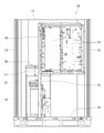
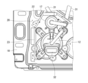
- FIG. 1 is a plan view showing the internal configuration of the outdoor unit including the compressor cover and the bottom plate of FIG. 1, excluding the top panel of the compressor cover.
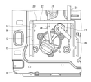
- the front view which shows the internal structure of the outdoor unit of FIG. 1, and shows the front panel of a compressor cover in a fluoroscopic state.
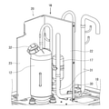
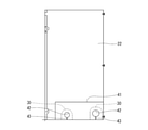
- the side view which shows the compressor cover of FIG. 1 excluding other side panels.
- FIG. 3 is a perspective view showing the front panels of FIGS. 1, 2 and 5.
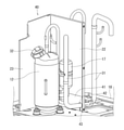
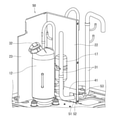
- FIG. 2 is a perspective view showing one side panel and the rear panel of the compressor cover of FIG. 2 together with a compressor to which piping is connected.
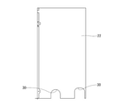
- FIG. 9 is a plan view showing a state in which the pipe is obliquely taken out from the pipe outlet of FIG. 9 and corresponding to FIG.
- the perspective view which shows the one side panel and the rear panel of a compressor cover which concerns on 2nd Embodiment together with a compressor to which a pipe is connected.
- the front view which shows the rear panel of FIG. 12 together with the waterproof main sheet.
- the perspective view which shows the one side panel and the rear panel of a compressor cover which concerns on 3rd Embodiment together with a compressor to which a pipe is connected.
- FIG. 14 is a front view showing a waterproof sub-sheet in contact with the waterproof main sheet attached to the rear panel of FIG. 14.
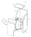
- FIG. 1 is a perspective view showing the compressor cover according to the first embodiment together with the bottom plate of the housing in the outdoor unit.
- 3 is a plan view showing the internal configuration of the outdoor unit including the compressor cover and the bottom plate of FIG. 1 excluding the top panel of the compressor cover
- FIG. 4 is a plan view of the outdoor unit of FIG. It is a front view which shows the internal structure and shows the front panel of a compressor cover in a fluoroscopic state.
- the compressor 12, the outdoor heat exchanger 13, the electrical component box 14, and the like constituting the refrigeration cycle are housed and installed in the housing 11 of the outdoor unit 10 of the air conditioner. Has been done.
- the outdoor heat exchanger 13 is formed in the vertical direction over the range of both side surfaces and the rear surface of the housing 11. Further, the electrical component box 14 is arranged in the front upper portion in the housing 11, and is supported by a frame 16 provided with a support column 15.
- the compressor 12 is covered with the compressor cover 20 together with the suction cup 17 for temporary storage of the refrigerant for the purpose of noise reduction and the like.
- the compressor cover 20 includes, for example, a front panel 21, a rear panel 22, one side panel 23, another side panel 24, and a top panel 25.
- the rear panel 22 is arranged to face the front panel 21.
- the one side panel 23 and the other side panel 24 are arranged to face each other between the front panel 21 and the rear panel 22.
- the top panel 25 closes the upper opening of the tubular body formed by the front panel 21, the rear panel 22, the one side panel 23, and the other side panel 24.
- the compressor cover 20 described above is erected from the bottom plate 18 of the housing 11, and the one side panel 23 and the other side panel 24 are fixed to the bottom plate 18 by using the fixing piece 26. Therefore, the compressor 12 is supported by the bottom plate 18 in the compressor cover 20.
- the compressor cover 20 may have a bottom plate for supporting the compressor 12 separately from the bottom plate 18 of the housing 11.
- the front panel 21 of the panels constituting the compressor cover 20 is positioned in front of the compressor 12 as shown in FIGS. 2 and 5. As shown in FIGS. 3 to 5, the front panel 21 is formed so that a portion overlapping the electrical component box 14 when viewed from the front is recessed in the depth direction A of the compressor cover 20.
- Reference numeral L1 in FIGS. 4 and 5 indicates the vertical recess length in the front panel 21.
- the front panel 21 includes a front first panel 27 and a front second panel 28.
- the front first panel 27 forms a vertical surface recessed in the depth direction A of the compressor cover 20. That is, the vertical length L2 of the vertical surface of the front surface first panel 27 corresponds to the recessed length L1.
- the upper surface portion 28A and the front surface portion 28B are integrally formed, and the upper surface portion 28A forms the above-mentioned recess of the front panel 21 together with the front surface first panel 27.
- the upper surface portion 28A of the front second panel 28 is continuously provided on the front first panel 27 without a gap in the assembled state of the compressor cover 20.
- the upper surface portion 28A of the front surface second panel 28 is formed so as to be inclined downward by an angle ⁇ with respect to the horizontal plane 29 toward the front surface portion 28B, and the flow of water is promoted.
- a pipe outlet 30 is formed at the lower part of the rear panel 22.
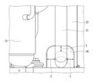
- the pipe outlet 30 is an inverted U-shaped notch including a straight portion, is opened downward, and the pipe 31 connected to the compressor 12 is inserted and taken out to the outside.
- the opening area of the pipe outlet 30 is set to be about 2 to 5 times larger than the cross-sectional area of the pipe 31.
- the gap T between the pipe 31 inserted into the pipe outlet 30 and the edge of the pipe outlet 30 is set to be approximately the diameter of the pipe 31. Therefore, for example, as shown in FIG. 11, the rear panel 22 of the compressor cover 20 is formed as a bent surface instead of a flat surface, and the pipe 31 is obliquely inserted into the pipe outlet 30 of the rear panel 22 of the bent surface. Even in this case, interference between the pipe 31 and the edge of the pipe outlet 30 is avoided.
- the front panel is positioned in front of the compressor 12. 21 is a front view, and a portion of the housing 11 that overlaps with the electrical component box 14 arranged in the front upper portion is formed so as to be recessed in the depth direction A. Therefore, at the time of maintenance of the compressor 12 or replacement of parts, the front second panel 28 of the front panel 21 of the compressor cover 20 can be attached / detached in a state where the electrical component box 14 is installed without being removed.
- a certain compressor 12 can be arranged in front of the center line 19 of the housing 11 and closer to the front portion where strength can be ensured in the housing 11.
- the front panel 21 of the compressor cover 20 covering the compressor 12 is configured to include the front first panel 27 and the front second panel 28. Therefore, for example, The state of the terminal portion 32 of the compressor 12 can be checked by simply removing the front second panel 28 during maintenance of the compressor 12.
- the upper surface portion 28A is inclined downward by an angle ⁇ with respect to the horizontal plane 29 toward the front surface portion 28B. Therefore, the flow of water that has fallen on the upper surface portion 28A is promoted. As a result, the progress of rust caused by the accumulation of rainwater on the upper surface portion 28A of the front second panel 28 can be suppressed.
- FIGS. 7 and 9 At least one panel of the front panel 21, the rear panel 22, the one side panel 23 and the other side panel 24 constituting the compressor cover 20, for example, the lower part of the rear panel 22.
- a pipe outlet 30 is formed which opens downward and allows the pipe 31 connected to the compressor 12 to be inserted and taken out to the outside. Therefore, when the pipe outlet 30 is formed on the top panel 25 of the compressor cover 20, or the pipe outlet 30 is formed on the front panel 21, the rear panel 22, the one side panel 23, or the other side panel 24.
- the waterproofness of the compressor cover 20 can be improved as compared with the case where the compressor cover 20 is used.
- the opening area of the pipe outlet 30 formed in the lower part of the rear panel 22 of the compressor cover 20 is the cross-sectional area of the pipe 31 inserted into the pipe outlet 30.
- the gap T between the pipe 31 and the edge of the pipe outlet 30 is set to be approximately 2 to 5 times larger than that of the pipe 31.
- FIG. 12 is a perspective view showing one side panel and the rear panel of the compressor cover according to the second embodiment together with the compressor to which the piping is connected.
- the same parts as those in the first embodiment are designated by the same reference numerals as those in the first embodiment to simplify or omit the description.
- the compressor cover 40 of the second embodiment is different from the first embodiment of at least one of the front panel 21, the rear panel 22, the one side panel 23, and the other side panel 24 constituting the compressor cover 40.
- a pipe outlet 30 is formed at the lower part of the panel, for example, the lower part of the rear panel 22, and the waterproof main sheet 41 is attached to the inner surface of the lower part of the rear panel 22 including the periphery of the pipe outlet 30.
- the waterproof main sheet 41 is made of an elastic material such as rubber or resin, and includes a pipe insertion hole 42 and a slit 43 communicating with the pipe insertion hole 42.
- the pipe insertion hole 42 is formed in a circular shape or an elliptical shape in which the long axis is located, for example, in the width direction of the rear panel 22.
- the opening area of the pipe insertion hole 42 of the waterproof main sheet 41 is set to be substantially the same as the cross-sectional area of the pipe 31.
- the pipe insertion hole 42 of the waterproof main sheet 41 is positioned at a position corresponding to the pipe outlet 30 of the rear panel 22.
- the slit 43 communicates with the pipe insertion hole 42 and extends downward to the lower edge of the waterproof main sheet 41.
- the compressor 12 is installed on the bottom plate 18 of the housing 11, and after the piping 31 is connected to the compressor 12, the rear panel 22 is lowered from above. At this time, the pipe 31 is guided into the pipe insertion hole 42 through the slit 43 of the waterproof main sheet 41, and together with the rear panel 22, the compressor is provided by the front panel 21, one side panel 23, the other side panel 24, and the top panel 25.
- a cover 40 is configured, and the compressor 12 is covered by the compressor cover 40.
- a waterproof main sheet 41 is attached to a range including the periphery of the pipe outlet 30 on the lower inner surface of the compressor cover 40, for example, the rear panel 22, and the waterproof main sheet 41 corresponds to the pipe outlet 30.
- a pipe insertion hole 42 for inserting the pipe 31 connected to the compressor 12 is formed at the position where the pipe is inserted, and a slit 43 communicating with the pipe insertion hole 42 is formed so as to extend to the lower edge of the waterproof main sheet 41. ing.
- the waterproof main sheet 41 closes the pipe outlet 30, which is a relatively large opening with respect to the cross-sectional area of the pipe 31, so that the water intrusion region of the pipe outlet 30 can be reduced. Further, it is possible to prevent the water droplets that have fallen on the bottom plate 18 of the housing 11 from infiltrating into the compressor cover 40 through the pipe outlet 30 due to the splashing up. From these things, the waterproof performance of the compressor cover 40 can be improved.
- the pipe insertion hole 42 formed in the waterproof main sheet 41 is formed in a circular shape or an elliptical shape.
- the oval-shaped pipe insertion hole 42 even if the pipe 31 inserted through the pipe insertion hole 42 varies, it is difficult for the waterproof main sheet 41 to be rolled up, so that the waterproof performance of the waterproof main sheet 41 is good. Can be secured.
- FIG. 14 is a perspective view showing one side panel and the rear panel of the compressor cover according to the third embodiment together with the compressor to which the piping is connected.
- the same parts as those in the first and second embodiments are designated by the same reference numerals as those in the first and second embodiments to simplify or omit the description.
- the compressor cover 50 of the third embodiment is different from the first and second embodiments among the front panel 21, the rear panel 22, the one side panel 23, and the other side panel 24 constituting the compressor cover 50.
- a pipe outlet 30 is formed at the lower part of at least one panel, for example, the lower part of the rear panel 22, and the waterproof main sheet 41 is attached to the inner surface of the lower part of the rear panel 22 including the periphery of the pipe outlet 30. This is a point where the waterproof sub-sheet 51 is provided in contact with the inner surface of the waterproof main sheet 41.
- the waterproof sub-sheet 51 is made of an elastic material such as rubber or resin, and includes a pipe insertion hole 52 and a slit 53 communicating with the pipe insertion hole 52.
- the pipe insertion hole 52 is formed in a circular shape, and the opening area is set to be the same as the cross-sectional area of the pipe 31.
- the slit 53 communicates with the pipe insertion hole 52 and extends upward to the upper edge of the waterproof sub-sheet 51.
- the waterproof sub-sheet 51 has a compressor 12 installed on the bottom plate 18 of the housing 11, and after the pipe 31 is connected to the compressor 12, the waterproof sub-sheet 51 is connected to the pipe 31.
- the insertion hole 52 is fitted through the slit 53, and the waterproof sub-sheet 51 is attached to the pipe 31.
- the rear panel 22 is lowered from above, and the pipe 31 to which the waterproof sub-sheet 51 is attached is guided through the slit 43 into the pipe insertion hole 42 of the waterproof main sheet 41 attached to the rear panel 22, and the waterproof sub-sheet is guided.
- the 51 is brought into contact with the waterproof main sheet 41.
- the compressor cover 50 is composed of the front panel 21, the one side panel 23, the other side panel 24, and the top panel 25, and the compressor 12 is covered by the compressor cover 50.
- the waterproof sub-sheet 51 is provided in contact with the inner surface of the waterproof main sheet 41 attached to the inner surface of the lower part of the rear panel 22 including the periphery of the pipe outlet 30, and the waterproof sub-sheet 51 is inserted into the pipe.
- the slit 53 communicating with the hole 52 is formed so as to extend upward in the direction opposite to the slit 43 communicating with the pipe insertion hole 42 of the waterproof main sheet 41. Therefore, even if the slit 43 of the waterproof main sheet 41 should open and the waterproof main sheet 41 is rolled up, the waterproof sub-sheet 51 can close the opening of the slit 43 and compress it from the periphery of the pipe 31. It is possible to reliably prevent water from entering the machine cover 50.
- the compressor covers 20, 40, and 50 are installed in the housing of the outdoor unit of the air conditioner, but they may be installed in the housing of the refrigerating equipment.
Landscapes
- Engineering & Computer Science (AREA)
- Chemical & Material Sciences (AREA)
- Combustion & Propulsion (AREA)
- Mechanical Engineering (AREA)
- General Engineering & Computer Science (AREA)
- Other Air-Conditioning Systems (AREA)
- Compressor (AREA)
Abstract
冷凍サイクルを構成する圧縮機及び熱交換器等を収納する筐体内で、強度を確保可能な前部寄りに、重量物である圧縮機を配置することができること。 冷凍サイクルを構成する圧縮機(12)、室外熱交換器(13)及び電装品箱(14)が室外ユニット(10)の筐体(11)内に設置され、この筐体内で圧縮機を覆う圧縮機カバー(20)であって、圧縮機(12)の前方に位置づけられる前面パネル(21)を備え、この前面パネル(21)は正面視で、筐体(11)内で前方上部に配置された電装品箱(14)と重なる部分が奥行き方向Aに凹んで形成されたものである。
Description
本発明の実施形態は、冷凍サイクルの一構成要素である圧縮機を覆う圧縮機カバーに関する。
空気調和装置の室外ユニットの筐体内には、冷凍サイクルを構成する圧縮機、室外熱交換器及び電装品箱などが収納されている。このうちの圧縮機は、特許文献1にも記載のように、騒音低減等を目的として圧縮機カバーにより覆われて、筐体内に設置されている。
上述の圧縮機は、重量物であるため、筐体において前部または後部の強度が確保されやすい位置に配置される必要がある。しかしながら、室外ユニット内の部品の配置制約上、電装品箱の配置位置によっては、圧縮機及び圧縮機カバーを筐体の中央位置寄りに配置せざるを得ない場合がある。この場合には、筐体の中央位置に特別な強度確保手段を施す必要が生ずる。
本発明の実施形態は、上述の事情を考慮してなされたものであり、冷凍サイクルを構成する圧縮機及び熱交換器等を収納する筐体内で、強度を確保可能な前部寄りに、重量物である圧縮機を配置することができる圧縮機カバーを提供することを目的とする。
本発明の実施形態における圧縮機カバーは、冷凍サイクルを構成する圧縮機、熱交換器及び電装品箱が筐体内に設置され、この筐体内で前記圧縮機を覆う圧縮機カバーであって、前記圧縮機の前方に位置づけられる前面パネルを備え、この前面パネルは正面視で、前記筐体内で前方上部に配置された前記電装品箱と重なる部分が奥行方向に凹んで形成されたことを特徴とするものである。
本発明の実施形態によれば、冷凍サイクルを構成する圧縮機及び熱交換器等を収納する筐体内で、強度を確保可能な前部寄りに、重量物である圧縮機を配置することができる。
以下、本発明を実施するための形態を、図面に基づき説明する。
[A]第1実施形態(図1~図11)
図1は、第1実施形態に係る圧縮機カバーを室外ユニットにおける筐体の底板と共に示す斜視図である。また、図3は、図1の圧縮機カバー及び底板を含む室外ユニットの内部構成を示し、圧縮機カバーの天面パネルを除いて示す平面図であり、図4は、図1の室外ユニットの内部構成を示し、圧縮機カバーの前面パネルを透視状態で示す正面図である。図3及び図4に示すように、空気調和装置の室外ユニット10における筐体11内には、冷凍サイクルを構成する圧縮機12、室外熱交換器13及び電装品箱14等が収納されて設置されている。
図1は、第1実施形態に係る圧縮機カバーを室外ユニットにおける筐体の底板と共に示す斜視図である。また、図3は、図1の圧縮機カバー及び底板を含む室外ユニットの内部構成を示し、圧縮機カバーの天面パネルを除いて示す平面図であり、図4は、図1の室外ユニットの内部構成を示し、圧縮機カバーの前面パネルを透視状態で示す正面図である。図3及び図4に示すように、空気調和装置の室外ユニット10における筐体11内には、冷凍サイクルを構成する圧縮機12、室外熱交換器13及び電装品箱14等が収納されて設置されている。
室外熱交換器13は、筐体11の両側面及び後面の範囲に亘って上下方向に形成される。また、電装品箱14は、筐体11内の前方上部に配置され、支柱15を備えたフレーム16により支持される。
圧縮機12は、図2及び図5にも示すように、騒音低減等を目的として、冷媒一時貯溜用のサクションカップ17と共に圧縮機カバー20に覆われる。この圧縮機カバー20は、図1及び図2に示すように、例えば前面パネル21、後面パネル22、一側面パネル23、他側面パネル24及び天面パネル25を有してなる。
後面パネル22は、前面パネル21に対向して配置される。一側面パネル23と他側面パネル24は、前面パネル21と後面パネル22との間で互いに対向配置される。天面パネル25は、前面パネル21、後面パネル22、一側面パネル23及び他側面パネル24により形成される筒形状体の上部開口を閉塞する。上述の圧縮機カバー20は、本実施形態では、筐体11の底板18から立設されており、一側面パネル23及び他側面パネル24が、固定片26を用いて底板18に固定される。従って、圧縮機12は、圧縮機カバー20内で底板18に支持される。なお、圧縮機カバー20は、圧縮機12を支持するための底板を、筐体11の底板18とは別に設けてもよい。
圧縮機カバー20を構成するパネルのうちの前面パネル21は、図2及び図5に示すように、圧縮機12の前方に位置づけられる。この前面パネル21は、図3~図5に示すように、正面視で電装品箱14と重なる部分が圧縮機カバー20の奥行き方向Aに凹んで形成されている。図4及び図5の符号L1は、前面パネル21における上下方向の凹み長さを示す。
更に前面パネル21は、図5及び図6に示すように、前面第1パネル27と前面第2パネル28とを有して構成される。前面第1パネル27が、圧縮機カバー20の奥行き方向Aに凹んだ垂直面を形成する。つまり、この前面第1パネル27の垂直面の上下方向長さL2は、上記凹み長さL1に相当する。
また、前面第2パネル28は、上面部28A及び前面部28Bが一体に形成され、上面部28Aが、前面第1パネル27と共に前面パネル21の上述の凹みを形成する。また、前面第2パネル28の上面部28Aは、圧縮機カバー20の組立状態では、前面第1パネル27に隙間なく連続して設けられる。更に、前面第2パネル28の上面部28Aは、図5に示すように、水平面29に対し角度θだけ、前面部28B側に下方へ傾斜して形成されて、水の流れが促進される。
上述の圧縮機カバー20を構成する前面パネル21、後面パネル22、一側面パネル23及び他側面パネル24のうちの少なくとも1つのパネルの下部、本実施形態では図7~図9に示すように、後面パネル22の下部に配管取出口30が形成されている。この配管取出口30は、直線部を含む逆U字形状の切欠きであり、下方に開口して、圧縮機12に接続された配管31を挿通し、外部へ取り出すものである。
この配管取出口30の開口面積は、図10に示すように、配管31の断面積よりも2~5倍程度大きく設定される。これにより、配管取出口30内に挿通される配管31と配管取出口30の縁との隙間Tが、配管31の略直径寸法程度に設定される。このため、例えば、図11に示すように、圧縮機カバー20の後面パネル22が平面ではなく屈曲面として形成され、この屈曲面の後面パネル22の配管取出口30に配管31が斜めに挿通される場合でも、配管31と配管取出口30の縁との干渉が回避される。
以上のように構成されたことから、本第1実施形態によれば、次の効果(1)~(6)を奏する。
(1)図1、図3及び図4に示すように、空気調和装置における室外ユニット10の筐体11内で圧縮機12を覆う圧縮機カバー20では、圧縮機12の前方に位置づけられる前面パネル21は正面視で、筐体11内で前方上部に配置された電装品箱14と重なる部分が奥行き方向Aに凹んで形成されている。従って、圧縮機12のメンテナンス時や部品交換時に、電装品箱14を取り外さず設置した状態で、圧縮機カバー20の前面パネル21の前面第2パネル28を着脱することができるので、重量物である圧縮機12を、筐体11のセンターライン19よりも前方の、筐体11内で強度を確保可能な前部寄りに配置することができる。
(1)図1、図3及び図4に示すように、空気調和装置における室外ユニット10の筐体11内で圧縮機12を覆う圧縮機カバー20では、圧縮機12の前方に位置づけられる前面パネル21は正面視で、筐体11内で前方上部に配置された電装品箱14と重なる部分が奥行き方向Aに凹んで形成されている。従って、圧縮機12のメンテナンス時や部品交換時に、電装品箱14を取り外さず設置した状態で、圧縮機カバー20の前面パネル21の前面第2パネル28を着脱することができるので、重量物である圧縮機12を、筐体11のセンターライン19よりも前方の、筐体11内で強度を確保可能な前部寄りに配置することができる。
(2)図1及び図2に示すように、圧縮機12を覆う圧縮機カバー20の前面パネル21が前面第1パネル27と前面第2パネル28とを有して構成されたので、例えば、圧縮機12のメンテナンス時に前面第2パネル28を取り外すだけで、圧縮機12のターミナル部32の状態などを確認することができる。
(3)図5に示すように、圧縮機カバー20の前面パネル21を構成する前面第2パネル28のうち、上面部28Aが水平面29に対し角度θだけ、前面部28B側に下方へ傾斜して形成されたので、上面部28Aに落下した水の流動が促進される。これにより、前面第2パネル28の上面部28Aに雨水が溜まることで生ずる錆の進行を抑制できる。
(4)図7及び図9に示すように、圧縮機カバー20を構成する前面パネル21、後面パネル22、一側面パネル23及び他側面パネル24の少なくとも1つのパネル、例えば後面パネル22の下部に、下方に開口して、圧縮機12に接続された配管31を挿通し外部へ取り出すための配管取出口30が形成されている。このため、圧縮機カバー20の天面パネル25に配管取出口30が形成される場合や、前面パネル21、後面パネル22、一側面パネル23または他側面パネル24の上部に配管取出口30が形成される場合に比べて、圧縮機カバー20の防水性を向上させることができる。
(5)圧縮機カバー20の例えば後面パネル22の下部に配管取出口30が形成されることで、室外ユニット10の製造時に圧縮機12に配管31を溶接した後、後面パネル22を含む圧縮機カバー20を設置することができるので、室外ユニット10の製造時の作業性を向上させることができる。
(6)図10及び図11に示すように、圧縮機カバー20における後面パネル22の下部に形成された配管取出口30の開口面積が、この配管取出口30に挿通される配管31の断面積よりも2~5倍程度大きく設定されて、配管31と配管取出口30の縁との隙間Tが配管31の略直径寸法程度に設定されている。これにより、配管31の製造時のバラツキに対しても、また配管31が配管取出口30に対し斜めに挿通される場合に対しても、配管31に配管取出口30の縁から過大な負荷が作用することを防止できる。
[B]第2実施形態(図12、図13)
図12は、第2実施形態に係る圧縮機カバーの一側面パネル及び後面パネルを、配管が接続された圧縮機と共に示す斜視図である。この第2実施形態において第1実施形態と同様な部分については、第1実施形態と同一の符号を付すことにより説明を簡略化し、または省略する。
図12は、第2実施形態に係る圧縮機カバーの一側面パネル及び後面パネルを、配管が接続された圧縮機と共に示す斜視図である。この第2実施形態において第1実施形態と同様な部分については、第1実施形態と同一の符号を付すことにより説明を簡略化し、または省略する。
本第2実施形態の圧縮機カバー40が第1実施形態と異なる点は、圧縮機カバー40を構成する前面パネル21、後面パネル22、一側面パネル23及び他側面パネル24のうちの少なくとも1のパネルの下部、例えば後面パネル22の下部に配管取出口30が形成されると共に、この配管取出口30の周囲を含む後面パネル22の下部内面に防水メインシート41が貼着された点である。
この防水メインシート41は、図13に示すように、ゴムや樹脂などの弾性材料から構成され、配管挿通孔42と、この配管挿通孔42に連通するスリット43とを備える。配管挿通孔42は、円形状、または長軸が例えば後面パネル22の幅方向に位置する楕円形状に形成されている。また、防水メインシート41の配管挿通孔42は、開口面積が配管31の断面積とほぼ同一に設定される。更に、防水メインシート41が後面パネル22の内面に貼着された状態で、防水メインシート41の配管挿通孔42は、後面パネル22の配管取出口30に対応する位置に位置づけられる。また、スリット43は、配管挿通孔42に連通すると共に、防水メインシート41の下縁まで下方に延びて形成されている。
この圧縮機カバー40では、図12に示すように、筐体11の底板18に圧縮機12が設置され、この圧縮機12に配管31が接続された後に、後面パネル22を上方から降ろし、この際に配管31を、防水メインシート41のスリット43を経て配管挿通孔42内に導き、この後面パネル22と共に、前面パネル21、一側面パネル23、他側面パネル24及び天面パネル25により圧縮機カバー40を構成して、この圧縮機カバー40により圧縮機12を覆う。
以上のように構成されたことから、本第2実施形態によれば、第1実施形態の効果(1)~(6)と同様な効果を奏するほか、次の効果(7)及び(8)を奏する。
(7)圧縮機カバー40の例えば後面パネル22の下部内面で、配管取出口30の周囲を含む範囲に防水メインシート41が貼着され、この防水メインシート41には、配管取出口30に対応する位置に、圧縮機12に接続された配管31を挿通する配管挿通孔42が形成されると共に、この配管挿通孔42に連通するスリット43が、防水メインシート41の下縁まで延びて形成されている。このように、配管31の断面積に対して比較的大きな開口である配管取出口30を防水メインシート41が塞ぐことで、この配管取出口30の水浸入領域を減少させることができる。また、筐体11の底板18に落下した水滴が跳ね上がりにより、配管取出口30を通して圧縮機カバー40内に浸入することも防止できる。これらのことから、圧縮機カバー40の防水性能を向上させることができる。
(8)防水メインシート41に形成された配管挿通孔42は、円形状または楕円形状に形成されている。特に楕円形状の配管挿通孔42では、この配管挿通孔42に挿通される配管31にバラツキがあっても防水メインシート41に捲れを生じさせ難くなるので、防水メインシート41の防水性能を良好に確保できる。
[C]第3実施形態(図14、図15)
図14は、第3実施形態に係る圧縮機カバーの一側面パネル及び後面パネルを、配管が接続された圧縮機と共に示す斜視図である。この第3実施形態において第1及び第2実施形態と同様な部分については、第1及び第2実施形態と同一の符号を付すことにより説明を簡略化し、または省略する。
図14は、第3実施形態に係る圧縮機カバーの一側面パネル及び後面パネルを、配管が接続された圧縮機と共に示す斜視図である。この第3実施形態において第1及び第2実施形態と同様な部分については、第1及び第2実施形態と同一の符号を付すことにより説明を簡略化し、または省略する。
本第3実施形態の圧縮機カバー50が第1及び第2実施形態と異なる点は、圧縮機カバー50を構成する前面パネル21、後面パネル22、一側面パネル23及び他側面パネル24のうちの少なくとも1のパネルの下部、例えば後面パネル22の下部に配管取出口30が形成され、この配管取出口30の周囲を含む後面パネル22の下部内面に防水メインシート41が貼着されると共に、この防水メインシート41の内面に防水サブシート51が接触して設けられた点である。
防水サブシート51は、図15に示すように、ゴムや樹脂などの弾性材料から構成され、配管挿通孔52と、この配管挿通孔52に連通するスリット53とを備える。配管挿通孔52は、円形状に形成されると共に、開口面積が配管31の断面積とを同一に設定される。また、スリット53は、配管挿通孔52に連通すると共に、防水サブシート51の上縁まで上方へ延びて形成されている。
防水サブシート51は、図14に示すように、筐体11の底板18に圧縮機12が設置され、この圧縮機12に配管31が接続された後に、この配管31に防水サブシート51の配管挿通孔52を、スリット53を通して嵌め込み、配管31に防水サブシート51を装着しておく。次に、後面パネル22を上方から降ろし、防水サブシート51が装着された配管31を、後面パネル22に貼着された防水メインシート41の配管挿通孔42内にスリット43を通して導き、防水サブシート51を防水メインシート41に接触させる。そして、この後面パネル22と共に、前面パネル21、一側面パネル23、他側面パネル24及び天面パネル25により圧縮機カバー50を構成して、この圧縮機カバー50により圧縮機12を覆う。
以上のように構成されたことから、本第3実施形態によれば、第1及び第2実施形態の効果(1)~(8)と同様な効果を奏するほか、次の効果(9)を奏する。
(9)後面パネル22の下部内面で配管取出口30の周囲を含む範囲に貼着された防水メインシート41の内面に防水サブシート51が接触して設けられ、この防水サブシート51の配管挿通孔52に連通するスリット53は、防水メインシート41の配管挿通孔42に連通するスリット43と反対方向の上方へ延びて形成されている。従って、防水メインシート41のスリット43が万一開口して防水メインシート41が捲れてしまった場合でも、そのスリット43の開口を防水サブシート51が塞ぐことができるので、配管31の周囲から圧縮機カバー50内への水の浸入を確実に防止することができる。
以上、本発明のいくつかの実施形態を説明したが、これらの実施形態は、例として提示したものであり、発明の範囲を限定することは意図していない。これらの実施形態は、その他の様々な形態で実施されることが可能であり、発明の要旨を逸脱しない範囲で、種々の省略、置き換え、変更を行うことができ、また、それらの置き換えや変更は、発明の範囲や要旨に含まれると共に、特許請求の範囲に記載された発明とその均等の範囲に含まれる。
例えば、本実施形態では、圧縮機カバー20、40、50が、空気調和装置の室外ユニットの筐体内に設置されるものを述べたが、冷凍機器の筐体内に設置されるものでもよい。
11…筐体、12…圧縮機、13…室外熱交換器、14…電装品箱、20…圧縮機カバー、21…前面パネル、22…後面パネル、23…一側面パネル、24…他側面パネル、27…前面第1パネル、28…前面第2パネル、28A…上面部、28B…前面部、30…配管取出口、31…配管、A…奥行き方向
Claims (4)
- 冷凍サイクルを構成する圧縮機、熱交換器及び電装品箱が筐体内に設置され、この筐体内で前記圧縮機を覆う圧縮機カバーであって、
前記圧縮機の前方に位置づけられる前面パネルを備え、この前面パネルは正面視で、前記筐体内で前方上部に配置された前記電装品箱と重なる部分が奥行方向に凹んで形成されたことを特徴とする圧縮機カバー。 - 前記前面パネルは、前記奥行方向に凹んだ垂直面を形成する前面第1パネルと、上面部及び前面部を備えてなる前面第2パネルとを有し、前記上面部が前記前面第1パネルに連続して設けられたことを特徴とする請求項1に記載の圧縮機カバー。
- 前記前面第2パネルの前記上面部が、水平面に対し前記前面部側に下方へ傾斜して形成されたことを特徴とする請求項2に記載の圧縮機カバー。
- 前記圧縮機を覆う前記前面パネル、後面パネル及び側面パネルの少なくとも1つのパネルの下部には、下方に開口して、前記圧縮機に接続された配管を外部へ取り出すための配管取出口が形成されたことを特徴とする請求項1乃至3のいずれか1項に記載の圧縮機カバー。
Applications Claiming Priority (2)
| Application Number | Priority Date | Filing Date | Title |
|---|---|---|---|
| JP2020154117A JP2023159476A (ja) | 2020-09-14 | 2020-09-14 | 圧縮機カバー |
| JP2020-154117 | 2020-09-14 |
Publications (1)
| Publication Number | Publication Date |
|---|---|
| WO2022054518A1 true WO2022054518A1 (ja) | 2022-03-17 |
Family
ID=80630431
Family Applications (1)
| Application Number | Title | Priority Date | Filing Date |
|---|---|---|---|
| PCT/JP2021/030271 Ceased WO2022054518A1 (ja) | 2020-09-14 | 2021-08-18 | 圧縮機カバー |
Country Status (2)
| Country | Link |
|---|---|
| JP (1) | JP2023159476A (ja) |
| WO (1) | WO2022054518A1 (ja) |
Citations (4)
| Publication number | Priority date | Publication date | Assignee | Title |
|---|---|---|---|---|
| JP2005036698A (ja) * | 2003-07-18 | 2005-02-10 | Mitsubishi Heavy Ind Ltd | 圧縮機の防音構造 |
| JP2010019463A (ja) * | 2008-07-09 | 2010-01-28 | Daikin Ind Ltd | 室外機 |
| JP2013204836A (ja) * | 2012-03-27 | 2013-10-07 | Fujitsu General Ltd | 空気調和機の室外機 |
| WO2018012556A1 (ja) * | 2016-07-13 | 2018-01-18 | ダイキン工業株式会社 | 空気処理装置における圧縮機カバー |
-
2020
- 2020-09-14 JP JP2020154117A patent/JP2023159476A/ja active Pending
-
2021
- 2021-08-18 WO PCT/JP2021/030271 patent/WO2022054518A1/ja not_active Ceased
Patent Citations (4)
| Publication number | Priority date | Publication date | Assignee | Title |
|---|---|---|---|---|
| JP2005036698A (ja) * | 2003-07-18 | 2005-02-10 | Mitsubishi Heavy Ind Ltd | 圧縮機の防音構造 |
| JP2010019463A (ja) * | 2008-07-09 | 2010-01-28 | Daikin Ind Ltd | 室外機 |
| JP2013204836A (ja) * | 2012-03-27 | 2013-10-07 | Fujitsu General Ltd | 空気調和機の室外機 |
| WO2018012556A1 (ja) * | 2016-07-13 | 2018-01-18 | ダイキン工業株式会社 | 空気処理装置における圧縮機カバー |
Also Published As
| Publication number | Publication date |
|---|---|
| JP2023159476A (ja) | 2023-11-01 |
Similar Documents
| Publication | Publication Date | Title |
|---|---|---|
| US7671275B2 (en) | Electrical connection box | |
| JP3523823B2 (ja) | 空気調和機の室外ユニット | |
| JP5556753B2 (ja) | 車両のデッキガーニッシュのシール材固定構造 | |
| WO2022054518A1 (ja) | 圧縮機カバー | |
| JP2011084093A (ja) | 車両前部構造 | |
| JP2956675B2 (ja) | 空気調和機 | |
| JP2011158108A (ja) | 空気調和装置の室外ユニット | |
| CN105805920A (zh) | 空调器、壳体组件及其后壳 | |
| US9219356B2 (en) | Electrical junction box | |
| CN115246300A (zh) | 车辆的通风设备结构 | |
| US11769993B2 (en) | Electrical junction box housing | |
| JP7497111B2 (ja) | 電気機器収納キャビネット用換気装置 | |
| CN112805183B (zh) | 装备有扬声器模块的机动车辆车身 | |
| JP7847922B2 (ja) | 電気電子機器収納用箱 | |
| EP1574789A2 (en) | Air conditioner | |
| JP3591388B2 (ja) | 空気調和機の室外機 | |
| JP2009058149A (ja) | 空気調和機の室外機 | |
| JP2002156129A (ja) | 空気調和機 | |
| CN210832297U (zh) | 空调外壳、空调室外机和空调器 | |
| CN218096317U (zh) | 一种外机壳体及空调外机 | |
| JPH1114102A (ja) | 空気調和機の室外機 | |
| JP4915100B2 (ja) | 空気調和機の室内機 | |
| JP4716159B2 (ja) | ブラケット取付部の水抜き構造 | |
| JP7637854B2 (ja) | 屋外フード | |
| JP2018127975A (ja) | 圧縮機 |
Legal Events
| Date | Code | Title | Description |
|---|---|---|---|
| 121 | Ep: the epo has been informed by wipo that ep was designated in this application |
Ref document number: 21866478 Country of ref document: EP Kind code of ref document: A1 |
|
| NENP | Non-entry into the national phase |
Ref country code: DE |
|
| 122 | Ep: pct application non-entry in european phase |
Ref document number: 21866478 Country of ref document: EP Kind code of ref document: A1 |
|
| NENP | Non-entry into the national phase |
Ref country code: JP |