WO2022054334A1 - 溶湯浸漬部材 - Google Patents
溶湯浸漬部材 Download PDFInfo
- Publication number
- WO2022054334A1 WO2022054334A1 PCT/JP2021/017641 JP2021017641W WO2022054334A1 WO 2022054334 A1 WO2022054334 A1 WO 2022054334A1 JP 2021017641 W JP2021017641 W JP 2021017641W WO 2022054334 A1 WO2022054334 A1 WO 2022054334A1
- Authority
- WO
- WIPO (PCT)
- Prior art keywords
- molten metal
- opening
- lid
- packing
- tubular member
- Prior art date
- Legal status (The legal status is an assumption and is not a legal conclusion. Google has not performed a legal analysis and makes no representation as to the accuracy of the status listed.)
- Ceased
Links
Images



Classifications
-
- H—ELECTRICITY
- H05—ELECTRIC TECHNIQUES NOT OTHERWISE PROVIDED FOR
- H05B—ELECTRIC HEATING; ELECTRIC LIGHT SOURCES NOT OTHERWISE PROVIDED FOR; CIRCUIT ARRANGEMENTS FOR ELECTRIC LIGHT SOURCES, IN GENERAL
- H05B3/00—Ohmic-resistance heating
- H05B3/40—Heating elements having the shape of rods or tubes
- H05B3/42—Heating elements having the shape of rods or tubes non-flexible
- H05B3/44—Heating elements having the shape of rods or tubes non-flexible heating conductor arranged within rods or tubes of insulating material
-
- H—ELECTRICITY
- H05—ELECTRIC TECHNIQUES NOT OTHERWISE PROVIDED FOR
- H05B—ELECTRIC HEATING; ELECTRIC LIGHT SOURCES NOT OTHERWISE PROVIDED FOR; CIRCUIT ARRANGEMENTS FOR ELECTRIC LIGHT SOURCES, IN GENERAL
- H05B3/00—Ohmic-resistance heating
- H05B3/78—Heating arrangements specially adapted for immersion heating
-
- Y—GENERAL TAGGING OF NEW TECHNOLOGICAL DEVELOPMENTS; GENERAL TAGGING OF CROSS-SECTIONAL TECHNOLOGIES SPANNING OVER SEVERAL SECTIONS OF THE IPC; TECHNICAL SUBJECTS COVERED BY FORMER USPC CROSS-REFERENCE ART COLLECTIONS [XRACs] AND DIGESTS
- Y02—TECHNOLOGIES OR APPLICATIONS FOR MITIGATION OR ADAPTATION AGAINST CLIMATE CHANGE
- Y02P—CLIMATE CHANGE MITIGATION TECHNOLOGIES IN THE PRODUCTION OR PROCESSING OF GOODS
- Y02P10/00—Technologies related to metal processing
- Y02P10/20—Recycling
Definitions
- the present invention relates to a heater immersed in a molten metal such as aluminum and a molten metal immersion member for protecting a thermocouple.
- a molten metal holding furnace that heats and keeps the molten metal at a suitable temperature is used.
- a heater for heating and retaining the molten metal and a thermocouple for detecting the temperature of the molten metal are protected by the molten metal dipping member and immersed.
- an L-shaped heater for molten metal is disclosed in Patent Documents 1 and 2.
- the heater for molten metal disclosed in Patent Documents 1 and 2 has a configuration in which a heating element contained therein can be taken in and out through an opening provided in a protective member having a bag tube shape. The opening is configured to be sealed by a lid.
- the heating element immersed in the molten metal is placed under high temperature conditions for a long period of time, it is necessary to perform regular maintenance. Further, the heating element may need to adjust the position of the heating element in order to appropriately heat the molten metal.
- the lid member disclosed in Patent Document 1 has a structure of fitting with the opening of the protective member or a structure of screwing, the fitting surface is while being immersed in the molten metal for a long period of time.
- molten metal infiltrates from the screwed surface and sticks to the mating surface or the screwed surface.
- the heating element housed inside the protective member cannot be taken out unless the opening of the protective member fixed to the lid member is destroyed as well as the lid member.
- the lid body disclosed in Patent Document 2 has a plurality of mounting holes, and has a structure in which the heat generating body is screw-fixed to the heat radiating pipe in these mounting holes, so that the lid can be used as a molten metal.
- the total length of the heating element exceeds 1 m, it is difficult to visually recognize the tip of the heating element inserted into the bag tube-shaped protective member having one end closed, so that it takes time to adjust the position. rice field.
- the present invention is to provide a molten metal dipping member that can be easily maintained and that minimizes the portion to be destroyed.
- the molten metal dipping member of the present invention made to solve the above problems is a molten metal dipping member immersed in a metal molten metal, and has a tubular member provided with an opening, a lid covering the opening, and the above. It is characterized by having a packing that closes between the opening and the lid. With this configuration, when the heater and the thermocouple immersed in the molten metal are maintained and the position is adjusted, the heater and the thermocouple can be maintained and the position is adjusted without destroying the tubular member. ..
- the molten metal dipping member of the present invention includes a heater inserted into the tubular member and a thermocouple without destroying the tubular member when maintaining or adjusting the position of the heater and the thermocouple immersed in the molten metal. Maintenance and position adjustment can be performed.
- FIG. 5 is a partially enlarged cross-sectional view of FIG. It is sectional drawing explaining another embodiment of the molten metal dipping member of embodiment which concerns on this invention.
- FIG. 1 is a schematic explanatory view showing a state in which the molten metal dipping member of the embodiment according to the present invention is arranged in the molten metal.
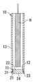
- FIG. 2 is a cross-sectional view of the molten metal dipping member according to the embodiment of the present invention.
- FIG. 3 is a partially enlarged cross-sectional view of the molten metal dipping member according to the embodiment of the present invention.
- FIG. 4 is an enlarged sectional view taken along the line A of FIG.
- the molten metal dipping member 10 is a molten metal dipping member 10 immersed in the metal molten metal M, and is a tubular member 13 provided with an opening 12, a lid 24 covering the opening 12, and an opening. It has a packing 31 that closes between the 12 and the lid 24.
- a female screw 11 is formed on the inner circumference of the opening 12, and the lid 24 is a male screw screwed with the opening 12.
- a shaft portion 22 on which 21 is formed and a head portion 23 projecting in the outer peripheral direction are provided at one end of the shaft portion 22, and a packing 31 is provided with an end surface 12a of the opening 12 and a seat surface 23a of the head portion 23. Block the space.
- the tubular member 13 is formed in a cylindrical shape.
- a portion 12 is provided.
- the other end side of the tubular member 13 is opened in a circular shape, and a heat generating element H for heating the molten metal M, a temperature measuring element (not shown) for detecting the temperature of the molten metal M, and the like are inserted.
- the tip of the heat generating element H inserted into the tubular member 13 is preferably fixed in a state of being inserted into a ring-shaped heat insulating board or the like (not shown).
- a plate-shaped heat insulating body (not shown) provided with a through hole through which a lead wire electrically connected to the heat generating element H can be inserted is provided. It is preferable that they are arranged. In such an embodiment, the heat generating element H is held in the tubular member 13.
- the tubular member 13 is formed of silicon carbide-based ceramics, silicon nitride-based ceramics, Sialon-based ceramics (SiAlON-based ceramics), or the like.
- the silicon nitride-based ceramics are preferably composed of silicon nitride (Si 3N 4 ) as a main component, and preferably contain at least one compound of a compound containing yttrium, a compound containing magnesium, or a compound containing aluminum.
- the compound containing yttrium include Y 2 O 3 , Y 2 Si 3 O 3 N 4 , Y 4 Si 2 O 7 N 2 , and oxynitride glass.
- magnesium-containing compound examples include MgO, Mg 2 SiO 4 , MgSiN 2 , and oxynitride glass.
- compound containing aluminum examples include Al 2 O 3 , Al 2 SiO 5 , and oxynitride glass (so-called AlON).
- composite ceramics of silicon nitride and silicon carbide are also suitable.
- the tubular member 13 preferably has a bending strength of 300 MPa or more and 1200 MPa or less. If the tubular member 13 satisfies this standard, it can be safely used for a long period of time even when immersed in the molten metal M.
- the bending strength of the tubular member 13 is a three-point bending strength and can be measured according to JIS R1601.
- the heat generating element H for heating the molten metal M inserted in the tubular member 13, for example, a heater is electrically connected to an external power source.
- the element inserted into the tubular member 13 may be a temperature measuring element for detecting the temperature of the molten metal M, for example, a thermocouple, instead of the heat generating element H for heating the molten metal M.
- the lid 24 is provided with a shaft portion 22 on which a male screw 21 screwed with the opening portion 12 of the tubular member 13 is formed, and a head portion 23 protruding in the outer peripheral direction at one end of the shaft portion 22.
- the opening 12 is sealed by screwing the male screw 21 formed on the shaft portion 22 and the female screw 11 formed on the opening 12.
- the lid 24 is formed of a material having a lower strength than the tubular member 13. Specifically, the strength of the lid 24 is preferably 10 MPa or more and 100 MPa or less. The strength of the lid 24 can be measured according to the JISR2213: 2005 bending strength test method for refractory bricks. Even if it is difficult to remove the lid 24 from the tubular member 13 during maintenance of the heat generating element H, the lid 24 can be destroyed and the heat generating element H can be maintained without damaging the tubular member 13. can.
- the packing 31 closes between the end surface 12a of the opening 12 and the seat surface 23a of the head 23. That is, as shown in FIG. 3, the packing 31 is arranged between the end surface 12a of the opening 12 and the seat surface 23a of the head 23. Further, from the viewpoint of improving the obstruction between the end surface 12a of the opening 12 and the seat surface 23a of the head 23 by the packing 31, the end surface 12a of the opening 12 and the seat surface 23a of the head 23 are closed.
- the thickness of the packing 31 is preferably 0.1 mm or more and 10 mm or less, and more preferably 0.2 mm or more and 5.0 mm or less.
- the packing 31 is preferably compressed to a thickness of 10% or more and 90% or less based on the thickness before the shaft portion 22 of the lid 24 is screwed into the opening 12 of the tubular member 13. Further, the packing 31 is compressed to a thickness of 30% or more and 60% or less based on the thickness before the shaft portion 22 of the lid 24 is screwed into the opening 12 of the tubular member 13. More preferred. With such a configuration, sufficient occlusion can be ensured by the packing 31 between the end surface 12a of the opening 12 and the seat surface 23a of the head 23.
- the packing 31 closes between the end surface 12a of the opening 12 and the seating surface 23a of the head portion 23, so that the metal is arranged even when the molten metal dipping member 10 is arranged in the molten metal M.
- Maintenance of the heat generating element H is performed because the molten metal M does not invade the threaded surface between the opening 12 and the shaft portion 22, and the lid 24 and the tubular member 13 are not fixed and integrated by the metal molten metal M. At this time, the lid 24 can be removed without damaging the tubular member 13.
- the packing 31 is formed of the ceramic fiber paper material shown below.
- Specific examples of the ceramic fiber paper material include alumina, silica, and mullite.
- the density of the packing 31 is preferably 100 kg / m 3 or more and 500 kg / m 3 or less.
- the normal temperature tensile strength of the packing 31 is preferably 0.01 MPa or more and 0.3 MPa or less in both the vertical direction and the horizontal direction.
- the packing 31 preferably has a hollow circular shape, and when the width dimension of the arc (that is, the dimension calculated from (outer diameter-inner diameter) / 2) is 3 mm or more and 10 mm or less, the packing 31 has sufficient strength and sealing property. It is preferable from the viewpoint of. Further, the inner diameter of the packing 31 is preferably such that a gap of 0.5 mm or more and 5 mm or less is provided with respect to the outer diameter of the shaft portion 22 of the lid 24.
- the molten metal dipping member 10 has a filling joint material 41 that fills the gap created by the packing 31 located between the head 23 of the lid 24 and the opening 12 of the tubular member 13.
- a filling joint material 41 that fills the gap created by the packing 31 located between the head 23 of the lid 24 and the opening 12 of the tubular member 13.
- the filling joint material 41 is preferably a material that can withstand use at a high temperature and does not easily absorb the molten metal M, for example, an alumina mortar material.
- molten metal dipping member 50 As a modification of the molten metal dipping member 10 according to the above-described embodiment, there is a molten metal dipping member 50 as shown in FIGS. 5 and 6.
- the same components are designated by the same reference numerals, and the description thereof will be omitted as appropriate.
- the molten metal dipping member 50 is a molten metal dipping member 50 immersed in the metal molten metal M, and includes a tubular member 53 provided with an opening 52 and a lid 64 covering the opening 52. , A packing 71 that closes between the opening 52 and the lid 64.
- the packing 71 closes between the stepped portion 54 of the opening 52 and the end surface 62a of the peripheral wall portion 62. That is, as shown in FIG. 6, the packing 71 is arranged between the step portion 54 of the opening 52 and the end surface 62a of the peripheral wall portion 62. Further, the thickness dimension, material, shape and the like of the packing 71 may be the same as the thickness dimension, material and shape of the packing 31.
- the molten metal dipping member 50 is a filling joint material that fills the gap created by the packing 71 located between the peripheral wall portion 62 of the lid 64 and the opening 52 of the tubular member 53, similarly to the molten metal dipping member 10.
- the molten metal dipping member 50 has a covering joint material 82 that covers the end surface 62a of the peripheral wall portion 62 of the lid 64 and the stepped portion 54 of the opening 52. Since the covering joint material 82 has the same configuration as the covering joint material 42, detailed description thereof will be omitted.
- the step of closing the opening 52 by the lid 64 of the molten metal dipping member 50 or the step of removing the lid 64, which is a modification of the present embodiment, is the same as each step of the molten metal dipping member 50.
- the explanation is omitted.
- the molten metal dipping member 50 which is a modification of the molten metal dipping member 10 according to the present embodiment, has a male screw 51 formed on the outer peripheral side of the tubular member 53, and it is easy to form the male screw 51, so that the manufacturing cost is high. Can be reduced. Further, it is easy to design the shape of the lid 64 to be suitable for the usage environment and the application.
- FIG. 7 Another embodiment of the present invention is a U-shaped molten metal dipping member 100 as shown in FIG. 7.
- the same components are designated by the same reference numerals, and the description thereof will be omitted as appropriate.
- the tubular member 131 has openings 12 and 12 formed at both ends thereof.
- the openings 12 and 12 are sealed by the lids 24 and 24, respectively.
- the packing 31 closes between the end surface 12a of the opening 12 and the seat surface 23a of the head 23.
- the filling joint material may be used to fill the gap created by the packing 31 located between the head 23 of the lid 24 and the opening 12 of the tubular member 131.
- the outer peripheral surface 23b of the head portion 23 of the lid 24 and the end surface 12a of the opening portion 12 of the tubular member 131 may be covered with the covering joint material.
- the invention disclosed in the present specification is specified by changing these partial configurations to other configurations disclosed in the present specification to the extent applicable, in addition to the configurations of the inventions and embodiments, or these. Includes those specified by adding other configurations disclosed in the present specification to the configurations of the above, or those specified by deleting these partial configurations to the extent that partial effects can be obtained.
- the embodiment of the present invention can be a T-shaped or L-shaped molten metal dipping member as appropriate, in addition to the linear or U-shaped molten metal dipping member described above.
- the tubular member according to the embodiment of the present invention has a shape in which an opening is formed at the end thereof, but the opening may be formed not at the end but at the outer peripheral surface.
Landscapes
- Waste-Gas Treatment And Other Accessory Devices For Furnaces (AREA)
- Resistance Heating (AREA)
- Furnace Details (AREA)
- Manufacture And Refinement Of Metals (AREA)
Priority Applications (3)
| Application Number | Priority Date | Filing Date | Title |
|---|---|---|---|
| CN202190000147.4U CN217370438U (zh) | 2020-09-08 | 2021-05-10 | 熔液浸渍构件 |
| JP2021564267A JP7316378B2 (ja) | 2020-09-08 | 2021-05-10 | 溶湯浸漬部材 |
| JP2023101743A JP7588182B2 (ja) | 2020-09-08 | 2023-06-21 | 溶湯浸漬部材 |
Applications Claiming Priority (2)
| Application Number | Priority Date | Filing Date | Title |
|---|---|---|---|
| JP2020-150787 | 2020-09-08 | ||
| JP2020150787 | 2020-09-08 |
Publications (1)
| Publication Number | Publication Date |
|---|---|
| WO2022054334A1 true WO2022054334A1 (ja) | 2022-03-17 |
Family
ID=80631527
Family Applications (1)
| Application Number | Title | Priority Date | Filing Date |
|---|---|---|---|
| PCT/JP2021/017641 Ceased WO2022054334A1 (ja) | 2020-09-08 | 2021-05-10 | 溶湯浸漬部材 |
Country Status (3)
| Country | Link |
|---|---|
| JP (2) | JP7316378B2 (https=) |
| CN (1) | CN217370438U (https=) |
| WO (1) | WO2022054334A1 (https=) |
Citations (4)
| Publication number | Priority date | Publication date | Assignee | Title |
|---|---|---|---|---|
| JPS6177588U (https=) * | 1984-10-29 | 1986-05-24 | ||
| JPH07216465A (ja) * | 1994-02-04 | 1995-08-15 | Mitsui Mining & Smelting Co Ltd | 金属溶湯濾過槽における溶湯加熱装置 |
| JP3184097U (ja) * | 2013-04-01 | 2013-06-13 | 恭胤 高藤 | 流体加熱装置 |
| JP2016134240A (ja) * | 2015-01-16 | 2016-07-25 | 中外商工株式会社 | ヒーター及びヒーターの製造方法 |
Family Cites Families (7)
| Publication number | Priority date | Publication date | Assignee | Title |
|---|---|---|---|---|
| US4871263A (en) * | 1988-05-16 | 1989-10-03 | Pyromation, Inc. | Protective tube for a temperature sensor |
| JP2562783B2 (ja) * | 1993-06-10 | 1996-12-11 | リョービ株式会社 | 溶湯の自動給湯装置 |
| JPH0743075A (ja) * | 1993-08-03 | 1995-02-10 | Riken Corp | 浸漬管ヒータ |
| JP2886138B2 (ja) * | 1996-11-29 | 1999-04-26 | 株式会社東芝 | 積層セラミックス及びその製造方法 |
| JP5107127B2 (ja) | 2008-04-23 | 2012-12-26 | 助川電気工業株式会社 | 溶融金属用電磁ポンプ |
| JP5672749B2 (ja) | 2010-04-01 | 2015-02-18 | 日立金属株式会社 | 溶融金属めっき浴用ロール |
| JP2013105553A (ja) | 2011-11-11 | 2013-05-30 | National Institute Of Advanced Industrial & Technology | 非鉄金属溶湯用ヒーターおよびその製造方法 |
-
2021
- 2021-05-10 CN CN202190000147.4U patent/CN217370438U/zh active Active
- 2021-05-10 JP JP2021564267A patent/JP7316378B2/ja active Active
- 2021-05-10 WO PCT/JP2021/017641 patent/WO2022054334A1/ja not_active Ceased
-
2023
- 2023-06-21 JP JP2023101743A patent/JP7588182B2/ja active Active
Patent Citations (4)
| Publication number | Priority date | Publication date | Assignee | Title |
|---|---|---|---|---|
| JPS6177588U (https=) * | 1984-10-29 | 1986-05-24 | ||
| JPH07216465A (ja) * | 1994-02-04 | 1995-08-15 | Mitsui Mining & Smelting Co Ltd | 金属溶湯濾過槽における溶湯加熱装置 |
| JP3184097U (ja) * | 2013-04-01 | 2013-06-13 | 恭胤 高藤 | 流体加熱装置 |
| JP2016134240A (ja) * | 2015-01-16 | 2016-07-25 | 中外商工株式会社 | ヒーター及びヒーターの製造方法 |
Also Published As
| Publication number | Publication date |
|---|---|
| JP2023123632A (ja) | 2023-09-05 |
| JP7588182B2 (ja) | 2024-11-21 |
| CN217370438U (zh) | 2022-09-06 |
| JP7316378B2 (ja) | 2023-07-27 |
| JPWO2022054334A1 (https=) | 2022-03-17 |
Similar Documents
| Publication | Publication Date | Title |
|---|---|---|
| US4984904A (en) | Apparatus for continuously measuring temperature of molten metal and method for making same | |
| ES2621389T3 (es) | Método de formar juntas refractarias selladas en recipientes de contención de metal, y recipientes que incluyen juntas selladas | |
| CN203801092U (zh) | 一种浸入式加热器 | |
| CN103308192B (zh) | 用于测量熔融金属温度的装置 | |
| WO2010073736A1 (ja) | 連続鋳造方法及びノズル加熱装置 | |
| US10462851B2 (en) | Molten metal holding furnace | |
| US20020089099A1 (en) | Molten metal holding furnace baffle/heater system | |
| WO2022054334A1 (ja) | 溶湯浸漬部材 | |
| CN109054467A (zh) | 一种热防护涂料及其应用 | |
| CN100351615C (zh) | 高温计 | |
| CN108476560A (zh) | 高温管状加热器 | |
| KR101944582B1 (ko) | 히터 튜브 | |
| JP3180665U (ja) | 溶融金属搬送取鍋 | |
| KR102801259B1 (ko) | Ft-ir 발열체 및 그 코팅방법 | |
| US10356850B2 (en) | Heater protective tube for molten metal holding furnace | |
| JP2010269353A (ja) | アルミニウムの連続鋳造用スパウト | |
| KR101819923B1 (ko) | 금속 용탕 침지용 히터 튜브 | |
| JP2025135111A (ja) | 浸漬ヒーター | |
| TW418136B (en) | Free slag-line sleeve | |
| CN101801563A (zh) | 中间升液件、其制造方法以及低压铸造装置 | |
| JP2024104796A (ja) | フラットヒーターおよびこれを用いた保持炉 | |
| GB2057828A (en) | Furnace electrode assembly | |
| JP6952397B2 (ja) | ヒータ | |
| JP3799630B2 (ja) | 非鉄溶融金属用浸漬管 | |
| JPS61159079A (ja) | 低融点金属用保持炉 |
Legal Events
| Date | Code | Title | Description |
|---|---|---|---|
| ENP | Entry into the national phase |
Ref document number: 2021564267 Country of ref document: JP Kind code of ref document: A |
|
| 121 | Ep: the epo has been informed by wipo that ep was designated in this application |
Ref document number: 21866295 Country of ref document: EP Kind code of ref document: A1 |
|
| NENP | Non-entry into the national phase |
Ref country code: DE |
|
| 122 | Ep: pct application non-entry in european phase |
Ref document number: 21866295 Country of ref document: EP Kind code of ref document: A1 |