WO2022054156A1 - 回転機コイルと回転電機、および回転機コイルの製造方法 - Google Patents
回転機コイルと回転電機、および回転機コイルの製造方法 Download PDFInfo
- Publication number
- WO2022054156A1 WO2022054156A1 PCT/JP2020/034056 JP2020034056W WO2022054156A1 WO 2022054156 A1 WO2022054156 A1 WO 2022054156A1 JP 2020034056 W JP2020034056 W JP 2020034056W WO 2022054156 A1 WO2022054156 A1 WO 2022054156A1
- Authority
- WO
- WIPO (PCT)
- Prior art keywords
- inorganic compound
- compound particles
- thermosetting resin
- coil
- outer peripheral
- Prior art date
- Legal status (The legal status is an assumption and is not a legal conclusion. Google has not performed a legal analysis and makes no representation as to the accuracy of the status listed.)
- Ceased
Links
Images


Classifications
-
- H—ELECTRICITY
- H02—GENERATION; CONVERSION OR DISTRIBUTION OF ELECTRIC POWER
- H02K—DYNAMO-ELECTRIC MACHINES
- H02K15/00—Processes or apparatus specially adapted for manufacturing, assembling, maintaining or repairing of dynamo-electric machines
- H02K15/10—Applying solid insulation to windings, stators or rotors, e.g. applying insulating tapes
-
- H—ELECTRICITY
- H02—GENERATION; CONVERSION OR DISTRIBUTION OF ELECTRIC POWER
- H02K—DYNAMO-ELECTRIC MACHINES
- H02K3/00—Details of windings
- H02K3/30—Windings characterised by the insulating material
-
- H—ELECTRICITY
- H02—GENERATION; CONVERSION OR DISTRIBUTION OF ELECTRIC POWER
- H02K—DYNAMO-ELECTRIC MACHINES
- H02K3/00—Details of windings
- H02K3/32—Windings characterised by the shape, form or construction of the insulation
- H02K3/34—Windings characterised by the shape, form or construction of the insulation between conductors or between conductor and core, e.g. slot insulation
-
- H—ELECTRICITY
- H02—GENERATION; CONVERSION OR DISTRIBUTION OF ELECTRIC POWER
- H02K—DYNAMO-ELECTRIC MACHINES
- H02K3/00—Details of windings
- H02K3/32—Windings characterised by the shape, form or construction of the insulation
- H02K3/40—Windings characterised by the shape, form or construction of the insulation for high voltage, e.g. affording protection against corona discharges
-
- Y—GENERAL TAGGING OF NEW TECHNOLOGICAL DEVELOPMENTS; GENERAL TAGGING OF CROSS-SECTIONAL TECHNOLOGIES SPANNING OVER SEVERAL SECTIONS OF THE IPC; TECHNICAL SUBJECTS COVERED BY FORMER USPC CROSS-REFERENCE ART COLLECTIONS [XRACs] AND DIGESTS
- Y02—TECHNOLOGIES OR APPLICATIONS FOR MITIGATION OR ADAPTATION AGAINST CLIMATE CHANGE
- Y02T—CLIMATE CHANGE MITIGATION TECHNOLOGIES RELATED TO TRANSPORTATION
- Y02T10/00—Road transport of goods or passengers
- Y02T10/60—Other road transportation technologies with climate change mitigation effect
- Y02T10/64—Electric machine technologies in electromobility
Definitions
- This application relates to a rotary machine coil, a rotary electric machine, and a method for manufacturing a rotary machine coil.
- a plurality of rotary machine coils in which an insulating portion is wound around a conductor portion in which wound conductor wires are bundled are formed on the inner peripheral side of a stator core. It is stored in the slot.
- the insulating portion is generally formed by impregnating a mica tape in which a fiber reinforcing material such as glass cloth is attached to a mica sheet and impregnating it with a thermosetting resin.
- an insulating structure in which the progress is delayed by advancing the local fracture while changing the direction by the nanoparticles dispersed in the insulating portion (see, for example, Patent Document 1).
- the simply dispersed nanoparticles can delay the progress of the discharge by changing the direction of growth for a small discharge, but the effect on a large discharge is low and the reliability is improved. Was difficult.
- the present application discloses a technique for solving the above-mentioned problems, and aims to obtain a highly reliable rotary machine coil or rotary electric machine.
- the rotary machine coil disclosed in the present application is a rotary machine coil wound around an iron core of a rotary electric machine, and is a conductor portion in which conductors arranged by winding are bundled, and a thermosetting resin filled in a mica tape and a void. It is provided with an outer peripheral insulator that covers the outer periphery of the conductor portion and insulates the conductor portion and the iron core, and softens the glass cloth fiber constituting the mica tape in the outer peripheral insulator. It is characterized in that inorganic compound particles having a melting point lower than the point are dispersed and arranged.
- the method for manufacturing a rotary machine coil disclosed in the present application is a step of winding a lead wire according to the iron core of a rotary electric machine to be wound, and winding mica tape around a conductor portion in which the lead wires arranged by the winding are bundled.
- the inorganic compound particles having a melting point lower than the softening point of the glass cloth fiber constituting the mica tape are supported on the mica tape before being impregnated with the thermosetting resin composition. It is characterized by further comprising any of a step and a step of mixing the inorganic compound particles into the thermosetting resin composition.
- the inorganic compound particles in the outer peripheral insulator are connected to form a protective layer, so that the rotation is highly reliable.
- a machine coil or a rotary electric machine can be obtained.
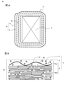
- 1A and 1B are a schematic cross-sectional view of the rotary machine coil according to the first embodiment and a schematic cross-sectional view of one layer of mica tape of the outer peripheral insulator, respectively.
- 2A and 2B are a partially enlarged view showing a storage state of the rotary machine coil in the stator according to the first embodiment, and a schematic cross-sectional view of a conductor portion of the rotary machine coil, respectively.
- 3A and 3B are cross-sections showing a combination of a mica tape and a composition of a thermosetting resin composition for explaining a method of blending different inorganic compound particles in the method for manufacturing a rotary coil according to the first embodiment. It is a schematic diagram.
- 5A and 5B are a cross-sectional view perpendicular to the axis of the rotary electric machine using the rotary machine coil according to the second embodiment and a cross-sectional view including the axis, respectively.
- Embodiment 1. 1 to 4 are for explaining the configuration of the rotary machine coil according to the first embodiment and the method for manufacturing the rotary machine coil
- FIG. 1 is a schematic cross-sectional view (FIG. 1A) of the rotary machine coil.
- FIG. 1B A schematic cross-sectional view of one layer of mica tape in the outer peripheral insulator (FIG. 1B)
- FIG. 2 is a partially enlarged view (FIG. 2A) showing the storage state of the rotating machine coil in the slot of the stator, and the conductor portion of the rotating machine coil. It is a cross-sectional schematic diagram (FIG. 2B) of.
- FIG. 3 is a schematic cross-sectional view (FIG. 3A) showing a combination of the composition of the mica tape of the first embodiment and the thermosetting resin composition for explaining different compounding methods of the inorganic compound particles in the method of manufacturing a rotary machine coil.
- FIG. 3B is a schematic cross-sectional view showing a combination of the composition of the mica tape of the second form and the thermosetting resin composition.
- FIG. 4 is a flowchart showing a method of manufacturing the rotary machine coil.
- the stator 10 is formed on a stator core 1 formed by laminating pattern-molded electrical steel sheets 1p in the axial direction. It is configured by combining a stator coil 2, which is a kind of rotary machine coil.
- FIG. 2A shows a state in which the two-stage stator coil 2 is housed inside the slot 1s in the radial direction (vertical direction in the figure).
- a spacer (not shown) is inserted between the two-stage stator coils 2, and a wedge 11 for fixing the stator coil 2 is inserted into the open end (upper side in the figure) of the slot 1s.
- the wedge 11 has an effect of suppressing electromagnetic vibration generated from the stator coil 2 during operation of the rotary electric machine 100.
- the conductor portion 3 constituting the stator coil 2 is a bundle of conductor wires 3u in which a flat metal wire 31 is covered with an insulating covering material 32 and wound in a coil shape.
- an insulating covering material 32 By covering the periphery thereof with the outer peripheral insulator 4, which will be described in detail later, insulation with the ground with the stator core 1 is formed.
- the outer peripheral insulator 4 is formed by winding a plurality of layers of mica tape 6 along the outer peripheral surface of the conductor portion 3 and impregnating the voids with a thermosetting resin 5.
- FIG. 1A a state is drawn in which a layer 4s corresponding to one layer of the mica tape 6 is wound from the lower left corner of the conductor portion 3 and wound in a total of three layers (the left side of the winding start is four layers).
- the mica tape 6 is formed by laminating the mica layer 6sm on which the mica particles 62 are laminated to the glass cloth layer 6sg with a binder or the like (not shown). Then, the inorganic compound particles 7 described later are dispersed and arranged in the thermosetting resin 5 in the outer peripheral insulator 4, in other words, in the gap formed by the mica particles 62 and the glass cloth fiber 61. It is characterized by.
- the mica layer 6sm of the mica tape 6 contains hard mica and soft mica, which are layered silicic acid-rimmed minerals, as main components, and examples thereof include block mica, peeled mica, and aggregated mica. Among these, it is preferable to use aggregated mica having a uniform thickness and having an economical advantage. From the viewpoint of withstand voltage, it is desirable that the content of mica particles 62 per area in the mica layer 6 sm is in the range of 60 to 200 g / m 2 . If it is less than 60 g / m 2 , the withstand voltage is inferior and the dielectric breakdown time at the time of power application deterioration becomes short. There is a problem that the thermal resistance of the body 4 increases.
- the mica particles 62 have a lint-like shape and are laminated in the thickness direction of the outer peripheral insulator 4 (mica tape 6). In the space where the thermosetting resin 5 or the inorganic compound particles 7 enter, the particles are arranged so as to be misaligned in various parts due to the overlapping portion of the laminated particles, the shape of the particles in the stacking direction, or the position of the particles. Existing.
- the glass cloth layer 6sg is impregnated with the strength of the tape, the improvement of the mechanical strength of the outer peripheral insulator 4, or the impregnation flow when the mica tape 6 is wound around the conductor portion 3 and impregnated with the thermosetting resin 5.
- a glass cloth fiber 61 suitable for forming a path is used.
- thermosetting resin As the thermosetting resin constituting the thermosetting resin 5, epoxy resin, phenol resin, silicon resin, and imide resin are preferable from the viewpoint of heat resistance, adhesiveness, electrical insulation, and mechanical strength, and among them, epoxy resin is particularly preferable. .. As a specific epoxy resin, an epoxy group is contained in the skeleton.
- Bisphenol A type epoxy resin bisphenol F type epoxy resin, bisphenol S type epoxy resin, biphenol type epoxy resin, phenol novolac type epoxy resin, cresol novolak type epoxy resin, bisphenol A type novolak type epoxy resin, bisphenol F type novolak type epoxy resin , Alicyclic epoxy resin, aliphatic chain epoxy resin, glycidyl ester type epoxy resin, glycidylamine type epoxy resin, hydantin type epoxy resin, isocyanurate type epoxy resin, salicylaldehyde novolak type epoxy resin, and other bifunctional phenols Diglycidyl etherified products, diglycidyl etherified products of bifunctional alcohols, their halides, hydrogenated products, etc.
- reaction product of epichlorohydrin and the bisphenol A compound is preferable from the viewpoint of the balance of cost, viscosity and heat resistance.
- examples of such products are Epicoat (registered trademark) 828, Epicoat 825 (manufactured by Yuka Shell Epoxy Co., Ltd.), Epototo (registered trademark) YD128 (manufactured by Toto Kasei Co., Ltd.), Epicron (registered trademark) 850 (Dainippon Ink). (Made by Chemical Industry Co., Ltd.), Sumiepoxy (registered trademark) ELA-128 (manufactured by Sumitomo Chemical Co., Ltd.) and the like can be mentioned.
- an epoxy resin containing three or more epoxy groups can be used alone or in combination with the above epoxy resin.
- the following can be mentioned.
- Resolsinol diglycidyl ether (1,3-bis- (2,3-epoxypropoxy) benzene), bisphenol A diglycidyl ether (2,2-bis (p- (2,3-epoxypropoxy) phenyl) propane), Triglycidyl p-aminophenol (4- (2,3-epoxypropoxy) -N, N-bis (2,3-epoxypropyl) aniline), diglycidyl ether of bromobisphenol A (2,2-bis (4-bis (4-)) (2,3-Epoxypropoxy) 3-bromo-phenyl) propane), bisphenol F diglycidyl ether (2,2-bis (p- (2,3-epoxypropoxy) phenyl) methane), (meth- / para -) Aminophenol triglycidyl ether (3- (2,3-epoxypropoxy) N, N-bis (2,3-epoxypropyl) aniline) and te
- the curing agent is not particularly limited as long as it can react with the epoxy resin to cure the epoxy resin, and examples thereof include the following acid anhydrides, amine compounds, and imidazole compounds.
- acid anhydrides examples include hexahydrophthalic anhydride, tetrahydrophthalic anhydride, methylhexahydrophthalic anhydride, methyltetrahydrophthalic anhydride, and methylnadic anhydride, which are used alone or in combination of two or more. be able to.
- the acid anhydride is preferably liquid at room temperature (25 ° C.). When the acid anhydride is a liquid at room temperature (25 ° C.), the viscosity of the thermosetting resin composition 5L (FIG. 3) can be lowered, so that the impregnation property of the thermosetting resin composition 5L is improved. be able to.
- the blending amount of the acid anhydride is not particularly limited, and may be appropriately adjusted according to the type of the acid anhydride to be used.
- the blending amount of the acid anhydride is preferably 10 parts by mass to 150 parts by mass, more preferably 30 parts by mass to 120 parts by mass, and further preferably 50 parts by mass to 100 parts by mass with respect to 100 parts by mass of the bisphenol type epoxy resin. be. With such a blending amount, the thermosetting resin composition 5L can be appropriately cured.
- the equivalent ratio of the acid anhydride group of the acid anhydride to the epoxy group of the bisphenol type epoxy resin is not particularly limited, but is preferably 0.7 to 1.3, more preferably 0.8 to 1.2, and further. It is preferably 0.9 to 1.1.
- this equivalent ratio is less than 0.3, the viscosity of the thermosetting resin composition 5L tends to be high.
- this equivalent ratio exceeds 1.3, the heat resistance of the cured product tends to decrease.
- the inorganic compound particles 7 dispersed and arranged in the thermosetting resin 5 constituting the outer peripheral insulator 4, which is a feature of the rotary machine coil (stator coil 2) of the present application, will be described. It is desirable that the inorganic compound particles 7 are higher than the thermal decomposition temperature Td of the thermosetting resin 5 and lower than the softening point (for example, 720 ° C.) of the glass cloth fiber 61. This enables melting due to heat generation due to partial discharge. Further, it is an insulating inorganic compound that can be crystallized after melting or is crystallized, and is arranged in the gap of the mica tape 6.
- thermogravimetric analysis was performed under the condition that the temperature rising rate was 90 K / min in a nitrogen atmosphere, and at a temperature (T d 10 ) at which the thermosetting resin 5 showed a mass reduction of 10 mass%.
- TGA thermogravimetric analysis
- the softening point is, for example, the temperature at which the elongation rate under its own weight becomes 1 mm / min when the temperature of the glass fiber is raised at 5 K / min (ISO 7884-6: 1987 (corresponding JIS R 3103-1: 2001). )) Is required.
- Examples of the inorganic compound that is the basis of the inorganic compound particles 7 include a composite component containing bismuth trioxide-zinc oxide-diboron trioxide, a composite component containing bismuth trioxide-silicon dioxide-zinc oxide, and zinc oxide-silicon dioxide.
- -A complex component containing bismuth trioxide or a complex component containing bismuth trioxide-diboron trioxide can be mentioned.
- Such an inorganic compound is characterized in that it melts (has a melting point of 400 ° C. or higher) by heating to 400 ° C. or higher, which is higher than the thermal decomposition temperature Td (250 to 350 ° C.) of a general epoxy resin. do.
- the melting point tends to be lowered.
- the melting point can be measured using a differential scanning calorimetry (DSC) at a temperature at which the inorganic compound softens and deforms due to its own weight when the inorganic compound is heated from room temperature.
- DSC differential scanning calorimetry
- the composition contains bismuth trioxide in the range of 20 mass% or more and 95 mass% or less. If it is less than 20 mass%, even when various additives are added, the melting point exceeds 700 ° C., the melting action at the time of discharge does not occur, and the desired effect of improving the withstand voltage resistance described later cannot be obtained. If it exceeds 95 mass%, the insulating property of the inorganic compound is lowered, and the volume resistance of the outer peripheral insulator 4 is lowered.
- the inorganic compound particles (inorganic compound particles 7) in the melting temperature range are dispersed in the outer peripheral insulator 4, if a partial discharge, which is a precursor phenomenon of dielectric breakdown, occurs, the partial discharge is eroded (heat). Decomposition) causes micropores (pits) in the thermosetting resin 5. However, at that time, the inorganic compound particles 7 around the pit are melted, deformed along the inner surface of the pit, connected to (the melt) of the nearby inorganic compound particles 7, and the inorganic material covering the inner surface of the pit is covered. Form a layer of compound (ceramic layer). Therefore, the ceramic layer formed in the pit can suppress the thermal decomposition of the thermosetting resin 5 around the pit, and can form a protective layer to improve the withstand voltage.
- the nanofiller shown in the prior art when, for example, the nanofiller shown in the prior art is used instead of the above-mentioned inorganic compound particles 7, the nanofiller has an insulating life in a low voltage region where minute discharges are repeatedly generated due to a physical barrier effect. The improvement effect of is obtained.
- the resin is eroded in a short time due to a large discharge, the nanofiller filled in the eroded resin needs to be gradually deposited and concentrated at the tip of the discharge progress, so that the nanofiller needs to be thickened. It was difficult to maintain reliability because erosion at a certain depth was unavoidable until the effect was exhibited.
- the withstand voltage is exhibited not only in the low voltage region but also in the high voltage region, and reliability is maintained. be able to.
- the inorganic compound containing bismuth trioxide as a main component has a relative permittivity of 5 or more, which is higher than that of the thermosetting resin 5, and as a result of easily accepting carrier electrons of electric discharge, thermal destruction due to partial discharge to the thermosetting resin 5 It has the effect of suppressing the progress of. In order to exhibit such an action, it is desirable that the relative permittivity of the inorganic compounds constituting the inorganic compound particles 7 is 5 or more and 120 or less.
- the above-mentioned inorganic compound particles 7 can be melted by heat generated by a minute discharge due to a partial discharge or the like, and then crystallized. As a result, a crystalline ceramic layer of an inorganic compound having high insulating properties is formed so as to surround the pits, and insulation progress due to discharge deterioration of the thermosetting resin 5 can be suppressed.
- inorganic compounds consisting of the above-mentioned complex components, for example, bismuth trioxide-zinc oxide-composite component containing diboron trioxide, bismuth trioxide-silicon dioxide-composite component containing zinc oxide, and zinc oxide-silicon dioxide-
- the complex component containing bismuth trioxide undergoes crystallization after melting. When crystallized, the withstand voltage can be further improved by forming a strong ceramic layer.
- the particle size of the inorganic compound particles 7 becomes smaller, the volume that melts during discharge becomes smaller, and the desired withstand voltage effect cannot be obtained.
- the particle size is large, the mica tape 6 cannot be formed in a densely laminated state, and the withstand voltage resistance is lowered. Since the distance between particles increases according to the particle size, the probability of trapping electrons tends to decrease during the above-mentioned partial discharge.
- the average particle size of the inorganic compound particles 7 is preferably 50 nm or more and 100 ⁇ m or less in terms of median diameter (50% diameter, D50), and more preferably 100 nm or more and 30 ⁇ m or less.
- a laser diffraction / scattering method particle size distribution device (Microtrac (registered trademark) MT3300) was used.
- the inorganic compound particles 7 are dispersed and present in the thermosetting resin 5.
- the filling rate (volume fraction at 25 ° C.) at that time is preferably in the range of 0.3 vol% or more and 30 vol% or less in the outer peripheral insulator 4, and more preferably 1 vol% or more and 15 vol% or less. If the filling rate is less than 0.3 vol%, the desired withstand voltage effect cannot be obtained, and if it exceeds 30 vol%, the relative permittivity of the outer peripheral insulator 4 increases and the starting voltage of the partial discharge decreases, so that the outer peripheral insulator is used. This is because the withstand voltage resistance as 4 is lowered.
- an insulating portion (corresponding to the outer peripheral insulator 4 of the present application) formed by impregnating mica tape with a thermosetting resin
- a general method for forming an insulating portion a mica tape is wrapped around a conductor portion several times, impregnated with a low-viscosity liquid thermosetting resin composition (insulating varnish) under reduced pressure, and then heat-pressed (vacuum). Pressurized impregnation method) is used. Further, a method (resin rich method) in which a semi-cured resin is placed on mica tape, the tape is wound around a conductor portion, and then heat-pressed is also used.
- the outer peripheral insulator 4 by a vacuum pressurization impregnation method, a resin rich method, or the like, as in the case of a general stator coil.
- the inorganic compound particles 7 can be blended in the outer peripheral insulator 4 by blending the thermosetting resin composition 5L and impregnating the mica tape 6. ..
- the surface of the mica tape 6 is coated with the inorganic compound particles 7 in advance, dried, wound around the conductor portion 3, and then impregnated with 5 L of the thermosetting resin composition and cured to be inorganic.
- the compound particles 7 can be blended in the outer peripheral insulator 4.
- the manufacturing method of the stator coil 2 of the present application will be described with reference to the flowchart of FIG.
- a forming method by the vacuum pressure impregnation method will be described as an example.
- the conductor wire 3u in which the metal wire 31 is covered with the insulating covering material 32 is wound in a coil shape according to the stator core 1 (the shape of the slot 1s) to be wound.
- Turn (step S110) A plurality of conductors 3u having a flat cross section arranged (stacked) by winding are bundled to form a conductor portion 3, and mica tape 6 is wound around the outer peripheral portion thereof (step S120).
- the mica tape 6 is wound around the conductor portion 3 which has been pre-dried, and the conductor portion 3 is impregnated with 5 L of the thermosetting resin composition. Specifically, pre-drying is performed in order to remove the moisture adhering to the wound mica tape 6 (step S130). Then, the moisture is removed, and the conductor portion 3 around which the mica tape 6 is wound is impregnated into the liquid thermosetting resin composition 5L in a reduced pressure atmosphere, and is pressurized to penetrate into the voids inside the mica tape 6. Step S140).
- thermosetting resin composition 5L is heat-cured in a temperature range of 90 ° C. to 180 ° C. in a state where the pressure is returned to normal pressure, and the thermosetting resin 5 and none (step S150) are used.
- the coil 2 can be formed.
- at least one of the mica tape 6 and the thermosetting resin composition 5L contains the inorganic compound particles 7.
- FIG. 5A is a sectional view of the rotary electric machine which is perpendicular to the axis and corresponds to the AA cut surface of FIG. 5B
- FIG. 5B Is a cross-sectional view of a rotary electric machine including a shaft and corresponding to the BB cut surface of FIG. 5A.
- the rotor portion is transparently drawn.
- the rotary electric machine 100 has the stator 10 having the stator coil 2 described in the first embodiment and the inner circumference of the stator 10. It includes a rotor 80 rotatably arranged coaxially on the side, and a housing 90 for accommodating the stator 10 and the rotor 80.
- the stator 10 is mainly composed of the stator core 1 having the stator coil 2 described above.
- the stator core 1 is formed by laminating a plurality of electrical steel sheets 1p as described in the first embodiment, it is integrated with the following members in order to maintain the shape.
- One is a plurality of (8 in this example) iron core tightening members 12 provided on the outer peripheral portion of the stator core 1 at predetermined intervals in the circumferential direction to tighten the stator core 1 in the axial direction.
- the other is provided on the outer peripheral portion of the stator core 1 at predetermined intervals in the axial direction, and is flat in the axial direction in which the stator core 1 is fastened and held in the rotation axis direction from the outer peripheral side of the core tightening member 12.
- the housing 90 has a cylindrical shape having a bearing (not shown) that surrounds the outer peripheral surface of the stator core 1 at intervals and maintains the rotary shaft 80x of the rotor 80 rotatably at both ends in the axial direction.
- the frame 91 is the main component. Then, in order to fix the stator core 1, the following members and the like are provided on the inner peripheral surface side of the frame 91.
- One is a plurality of ring-shaped (five places in this example) middle frame members 92 projecting in the axial direction at predetermined intervals in the axial direction.
- one is a plurality of (four in this example) elastic support members 93 composed of spring plates fixed to each other and fixed to the holding ring 13 at the central portion in the axial direction.
- the rotary electric machine 100 configured in this way can have a high withstand voltage of the stator coil 2, it is possible to further increase the output and reduce the size.
- the configuration of the rotary electric machine 100 is applied to a turbine generator, it is possible to reduce the thickness of the insulating material around the conductor portion 3 by increasing the withstand voltage of the outer peripheral insulator 4, thereby dissipating heat from the conductor portion 3. It becomes possible to suppress the high temperature and improve the output efficiency of the generator.
- the number of laminated conductors 3u in the conductor portion 3 and the number of turns (number of layers) of the mica tape 6 wound around the conductor portion 3 are not limited to the examples shown in FIGS. 1 and 2, and can be appropriately changed. Further, it is assumed that at least one component such as the number of stages per slot 1s and the number of poles (8 poles in FIG. 5) is modified, added or omitted. Further, the stator coil 2 is taken as an example as the rotor coil, but the present invention is not limited to this, and the rotor coil used for the rotor 80 may be used. Further, for example, the inorganic compound particles 7 may be blended in both the form shown in FIG. 3A and the form shown in FIG. 3B.
- the rotary machine coil (fixed child coil 2) wound around the iron core (for example, the stator core 1) of the rotary electric machine 100.
- the particles 7 are configured to be dispersed and arranged, the inorganic compound particles 7 in the outer peripheral insulator 4 are not disturbed by the deformation of the glass cloth fiber 61 when a partial discharge occurs. Is melted and deformed to form a protective layer made of a ceramic layer, so that a highly reliable rotary machine coil (fixed child coil) or rotary electric machine 100 can be obtained.
- the formed protective layer can firmly fulfill the barrier function.
- the outer peripheral insulation is more reliably performed without breaking the shape of the outer peripheral insulator 4 due to the deformation of the glass cloth fiber 61 when a partial discharge occurs.
- the inorganic compound particles 7 in the body 4 are melted and deformed, and can be connected to form a protective layer by a ceramic layer.
- the inorganic compound particles 7 are composed of a composite component containing bismuth trioxide-zinc oxide-diboron trioxide, they not only have the above-mentioned thermal properties but also crystallize after melting to provide insulating properties as a protective layer. Is also excellent.
- the average particle size of the inorganic compound particles 7 is in the range of 50 nm or more and 100 ⁇ m or less, the laminated state of the mica tape 6 or the dispersed state of the inorganic compound particles 7 is good, and the withstand voltage resistance is surely obtained. be able to.
- the content of the inorganic compound particles 7 in the outer peripheral insulator 4 is in the range of 0.3 vol% or more and 30 vol% or less with respect to the outer peripheral insulator 4, the withstand voltage effect and the withstand voltage resistance as the outer peripheral insulator 4 are obtained. It can be compatible.
- the stator 10 the rotor 80 coaxially arranged on the inner peripheral surface side of the stator 10, and the stator 10 are held, and the rotor 80 can be rotated.
- the stator 10 and the rotor 80 are provided with the rotor coil described in the first embodiment, so that the rotary electric machine 100 is compact and highly reliable. can get.
- the step of winding the lead wire 3u according to the iron core (for example, the stator core 1) of the rotary electric machine 100 to be wound (Step S110), a step of winding the mica tape 6 around the conductor portion 3 in which the conductors 3u arranged by winding are bundled (step S120), and a step of impregnating the mica tape 6 with the liquid thermosetting resin composition 5L (step).
- step S140 and a step (step S150) of heating and curing the impregnated thermosetting resin composition 5L to form an outer peripheral insulator 4 that insulates the conductor portion 3 and the iron core, constituting the mica tape 6.
- thermosetting resin composition 5L A step of supporting the inorganic compound particles 7 having a melting point lower than the softening point of the glass cloth fiber 61 on the mica tape 6 before impregnating the thermosetting resin composition 5L (before step S120: FIG. 3B). , And any of the steps of mixing the inorganic compound particles 7 having the above-mentioned properties into the thermosetting resin composition 5L (before step S140: FIG. 3A) are further included. Since the inorganic compound particles 7 in the outer peripheral insulator 4 are melted and deformed and connected to form a protective layer made of a ceramic layer, a highly reliable rotary machine coil (fixed child coil) or rotary electric machine 100 can be obtained. can.
Landscapes
- Engineering & Computer Science (AREA)
- Power Engineering (AREA)
- Manufacturing & Machinery (AREA)
- Insulation, Fastening Of Motor, Generator Windings (AREA)
- Manufacture Of Motors, Generators (AREA)
Priority Applications (2)
| Application Number | Priority Date | Filing Date | Title |
|---|---|---|---|
| PCT/JP2020/034056 WO2022054156A1 (ja) | 2020-09-09 | 2020-09-09 | 回転機コイルと回転電機、および回転機コイルの製造方法 |
| JP2022548285A JP7292525B2 (ja) | 2020-09-09 | 2020-09-09 | 回転機コイルと回転電機、および回転機コイルの製造方法 |
Applications Claiming Priority (1)
| Application Number | Priority Date | Filing Date | Title |
|---|---|---|---|
| PCT/JP2020/034056 WO2022054156A1 (ja) | 2020-09-09 | 2020-09-09 | 回転機コイルと回転電機、および回転機コイルの製造方法 |
Publications (1)
| Publication Number | Publication Date |
|---|---|
| WO2022054156A1 true WO2022054156A1 (ja) | 2022-03-17 |
Family
ID=80631377
Family Applications (1)
| Application Number | Title | Priority Date | Filing Date |
|---|---|---|---|
| PCT/JP2020/034056 Ceased WO2022054156A1 (ja) | 2020-09-09 | 2020-09-09 | 回転機コイルと回転電機、および回転機コイルの製造方法 |
Country Status (2)
| Country | Link |
|---|---|
| JP (1) | JP7292525B2 (https=) |
| WO (1) | WO2022054156A1 (https=) |
Cited By (1)
| Publication number | Priority date | Publication date | Assignee | Title |
|---|---|---|---|---|
| JP2023101093A (ja) * | 2022-01-07 | 2023-07-20 | 日立Astemo株式会社 | 回転電機の固定子 |
Citations (11)
| Publication number | Priority date | Publication date | Assignee | Title |
|---|---|---|---|---|
| JPH0961078A (ja) * | 1995-08-30 | 1997-03-07 | Matsushita Electric Works Ltd | 蓄熱ボード |
| JP2002330562A (ja) * | 2001-04-27 | 2002-11-15 | Toshiba Corp | 回転電機のコイル及びこのコイルの絶縁に用いられるマイカーテープ |
| US20050016658A1 (en) * | 2003-07-24 | 2005-01-27 | Thangavelu Asokan | Composite coatings for ground wall insulation in motors, method of manufacture thereof and articles derived therefrom |
| JP2006246599A (ja) * | 2005-03-02 | 2006-09-14 | Toshiba Corp | 半導電性テープ、半導電性テープの製造方法、絶縁コイル及び回転電機 |
| JP2009290973A (ja) * | 2008-05-28 | 2009-12-10 | Toshiba Corp | 回転電機の固定子コイル、回転電機の固定子コイルの製造方法および回転電機 |
| JP2010031425A (ja) * | 2008-07-30 | 2010-02-12 | Nitto Boseki Co Ltd | ガラスクロスの製造方法及びガラスクロス |
| US20130341068A1 (en) * | 2010-11-10 | 2013-12-26 | Cogebi S.A. | Mica-based strip |
| JP5611485B1 (ja) * | 2013-01-10 | 2014-10-22 | 三菱電機株式会社 | 絶縁テープ及びその製造方法、並びに固定子コイル |
| JP2016105688A (ja) * | 2011-11-14 | 2016-06-09 | 三菱電機株式会社 | 電磁コイル及びその製造方法 |
| WO2017014202A1 (ja) * | 2015-07-17 | 2017-01-26 | 日立化成株式会社 | 回転電機用コイル、回転電機用コイルの製造方法及びマイカテープ |
| JP2018014387A (ja) * | 2016-07-20 | 2018-01-25 | 住友電工ファインポリマー株式会社 | 基板、フレキシブルプリント配線板用基材、フレキシブルプリント配線板及び基板の製造方法 |
Family Cites Families (2)
| Publication number | Priority date | Publication date | Assignee | Title |
|---|---|---|---|---|
| CN103476155B (zh) * | 2013-09-13 | 2015-03-04 | 李琴 | 涂有无机厚膜的云母发热基板及其制备方法和发热组件 |
| CN103476156B (zh) * | 2013-09-13 | 2015-03-04 | 简伟雄 | 涂有无机厚膜的微晶玻璃发热基板及制备方法和发热组件 |
-
2020
- 2020-09-09 WO PCT/JP2020/034056 patent/WO2022054156A1/ja not_active Ceased
- 2020-09-09 JP JP2022548285A patent/JP7292525B2/ja active Active
Patent Citations (11)
| Publication number | Priority date | Publication date | Assignee | Title |
|---|---|---|---|---|
| JPH0961078A (ja) * | 1995-08-30 | 1997-03-07 | Matsushita Electric Works Ltd | 蓄熱ボード |
| JP2002330562A (ja) * | 2001-04-27 | 2002-11-15 | Toshiba Corp | 回転電機のコイル及びこのコイルの絶縁に用いられるマイカーテープ |
| US20050016658A1 (en) * | 2003-07-24 | 2005-01-27 | Thangavelu Asokan | Composite coatings for ground wall insulation in motors, method of manufacture thereof and articles derived therefrom |
| JP2006246599A (ja) * | 2005-03-02 | 2006-09-14 | Toshiba Corp | 半導電性テープ、半導電性テープの製造方法、絶縁コイル及び回転電機 |
| JP2009290973A (ja) * | 2008-05-28 | 2009-12-10 | Toshiba Corp | 回転電機の固定子コイル、回転電機の固定子コイルの製造方法および回転電機 |
| JP2010031425A (ja) * | 2008-07-30 | 2010-02-12 | Nitto Boseki Co Ltd | ガラスクロスの製造方法及びガラスクロス |
| US20130341068A1 (en) * | 2010-11-10 | 2013-12-26 | Cogebi S.A. | Mica-based strip |
| JP2016105688A (ja) * | 2011-11-14 | 2016-06-09 | 三菱電機株式会社 | 電磁コイル及びその製造方法 |
| JP5611485B1 (ja) * | 2013-01-10 | 2014-10-22 | 三菱電機株式会社 | 絶縁テープ及びその製造方法、並びに固定子コイル |
| WO2017014202A1 (ja) * | 2015-07-17 | 2017-01-26 | 日立化成株式会社 | 回転電機用コイル、回転電機用コイルの製造方法及びマイカテープ |
| JP2018014387A (ja) * | 2016-07-20 | 2018-01-25 | 住友電工ファインポリマー株式会社 | 基板、フレキシブルプリント配線板用基材、フレキシブルプリント配線板及び基板の製造方法 |
Cited By (2)
| Publication number | Priority date | Publication date | Assignee | Title |
|---|---|---|---|---|
| JP2023101093A (ja) * | 2022-01-07 | 2023-07-20 | 日立Astemo株式会社 | 回転電機の固定子 |
| JP7788283B2 (ja) | 2022-01-07 | 2025-12-18 | Astemo株式会社 | 回転電機の固定子 |
Also Published As
| Publication number | Publication date |
|---|---|
| JP7292525B2 (ja) | 2023-06-16 |
| JPWO2022054156A1 (https=) | 2022-03-17 |
Similar Documents
| Publication | Publication Date | Title |
|---|---|---|
| EP3101665B1 (en) | Insulating tape and manufacturing method therefor, stator coil and manufacturing method therefor, and rotating electrical machine | |
| EP2418079B1 (en) | Dry mica tape and instruction coils manufactured therewith | |
| JPH0377203A (ja) | 電気絶縁線輪、回転電機及びその製造方法 | |
| EP2945169B1 (en) | Insulation tape, method for producing same and stator coil | |
| CN108028092A (zh) | 固体的、特别地带状的绝缘材料、用于在真空浸渍工艺中由此制备绝缘体系的浸渍剂配制物和具有这种绝缘体系的机器 | |
| JPWO2016104141A1 (ja) | 絶縁テープ及びその製造方法、並びに固定子コイル及びその製造方法、並びに発電機 | |
| US20190149006A1 (en) | Method for producing corona discharge-preventing structure, corona discharge-preventing structure, and rotating electrical machine | |
| EP3486285B1 (en) | Thermally curable resin composition, stator coil obtained using same, and dynamo-electric machine | |
| JP2016072301A (ja) | 絶縁材、この絶縁材を用いた絶縁コイル、これらの製造方法、ならびにこの絶縁コイルを具備する装置 | |
| US20180215129A1 (en) | Functionally graded material, coil, insulation spacer, insulation device, and method for manufacturing functionally graded material | |
| JP2010158113A (ja) | 電気絶縁部材、回転電機用固定子コイルおよび回転電機 | |
| JP7292525B2 (ja) | 回転機コイルと回転電機、および回転機コイルの製造方法 | |
| JP5940210B2 (ja) | 回転式機械用の絶縁材料 | |
| GB1574986A (en) | Stator core and method of forming the same | |
| JP4560982B2 (ja) | 高圧回転機用絶縁コイルの製造方法 | |
| JP7203285B1 (ja) | 回転機コイル、その製造方法および回転機 | |
| JP5766352B2 (ja) | 回転電機固定子コイル絶縁用液状熱硬化性樹脂組成物、それを用いた回転電機及びその製造方法 | |
| WO2019077793A1 (ja) | 固定子コイルの絶縁被覆材およびそれを用いた回転機 | |
| KR20150003770A (ko) | 고전압 회전기계용 전기 절연체 및 전기 절연체를 생산하는 방법 | |
| WO2017097561A1 (en) | Conductor arrangement with insulation for an electrical machine | |
| JPH083337A (ja) | プリプレグ | |
| WO2026033866A1 (ja) | 絶縁用テープ、絶縁コイル、回転機、及び絶縁コイル製造方法 | |
| JPS62247739A (ja) | 電気絶縁線輪の製造方法 |
Legal Events
| Date | Code | Title | Description |
|---|---|---|---|
| 121 | Ep: the epo has been informed by wipo that ep was designated in this application |
Ref document number: 20953222 Country of ref document: EP Kind code of ref document: A1 |
|
| ENP | Entry into the national phase |
Ref document number: 2022548285 Country of ref document: JP Kind code of ref document: A |
|
| NENP | Non-entry into the national phase |
Ref country code: DE |
|
| 122 | Ep: pct application non-entry in european phase |
Ref document number: 20953222 Country of ref document: EP Kind code of ref document: A1 |