WO2022045373A1 - 感光体ユニット、カートリッジ、電子写真画像形成装置 - Google Patents
感光体ユニット、カートリッジ、電子写真画像形成装置 Download PDFInfo
- Publication number
- WO2022045373A1 WO2022045373A1 PCT/JP2021/032565 JP2021032565W WO2022045373A1 WO 2022045373 A1 WO2022045373 A1 WO 2022045373A1 JP 2021032565 W JP2021032565 W JP 2021032565W WO 2022045373 A1 WO2022045373 A1 WO 2022045373A1
- Authority
- WO
- WIPO (PCT)
- Prior art keywords
- gear portion
- photoconductor
- tooth
- rotation axis
- oblique tooth
- Prior art date
Links
Images


Classifications
-
- G—PHYSICS
- G03—PHOTOGRAPHY; CINEMATOGRAPHY; ANALOGOUS TECHNIQUES USING WAVES OTHER THAN OPTICAL WAVES; ELECTROGRAPHY; HOLOGRAPHY
- G03G—ELECTROGRAPHY; ELECTROPHOTOGRAPHY; MAGNETOGRAPHY
- G03G21/00—Arrangements not provided for by groups G03G13/00 - G03G19/00, e.g. cleaning, elimination of residual charge
- G03G21/16—Mechanical means for facilitating the maintenance of the apparatus, e.g. modular arrangements
- G03G21/18—Mechanical means for facilitating the maintenance of the apparatus, e.g. modular arrangements using a processing cartridge, whereby the process cartridge comprises at least two image processing means in a single unit
- G03G21/1839—Means for handling the process cartridge in the apparatus body
- G03G21/1857—Means for handling the process cartridge in the apparatus body for transmitting mechanical drive power to the process cartridge, drive mechanisms, gears, couplings, braking mechanisms
-
- F—MECHANICAL ENGINEERING; LIGHTING; HEATING; WEAPONS; BLASTING
- F16—ENGINEERING ELEMENTS AND UNITS; GENERAL MEASURES FOR PRODUCING AND MAINTAINING EFFECTIVE FUNCTIONING OF MACHINES OR INSTALLATIONS; THERMAL INSULATION IN GENERAL
- F16H—GEARING
- F16H1/00—Toothed gearings for conveying rotary motion
- F16H1/02—Toothed gearings for conveying rotary motion without gears having orbital motion
- F16H1/04—Toothed gearings for conveying rotary motion without gears having orbital motion involving only two intermeshing members
- F16H1/06—Toothed gearings for conveying rotary motion without gears having orbital motion involving only two intermeshing members with parallel axes
- F16H1/08—Toothed gearings for conveying rotary motion without gears having orbital motion involving only two intermeshing members with parallel axes the members having helical, herringbone, or like teeth
-
- G—PHYSICS
- G03—PHOTOGRAPHY; CINEMATOGRAPHY; ANALOGOUS TECHNIQUES USING WAVES OTHER THAN OPTICAL WAVES; ELECTROGRAPHY; HOLOGRAPHY
- G03G—ELECTROGRAPHY; ELECTROPHOTOGRAPHY; MAGNETOGRAPHY
- G03G15/00—Apparatus for electrographic processes using a charge pattern
- G03G15/75—Details relating to xerographic drum, band or plate, e.g. replacing, testing
- G03G15/757—Drive mechanisms for photosensitive medium, e.g. gears
-
- G—PHYSICS
- G03—PHOTOGRAPHY; CINEMATOGRAPHY; ANALOGOUS TECHNIQUES USING WAVES OTHER THAN OPTICAL WAVES; ELECTROGRAPHY; HOLOGRAPHY
- G03G—ELECTROGRAPHY; ELECTROPHOTOGRAPHY; MAGNETOGRAPHY
- G03G21/00—Arrangements not provided for by groups G03G13/00 - G03G19/00, e.g. cleaning, elimination of residual charge
- G03G21/16—Mechanical means for facilitating the maintenance of the apparatus, e.g. modular arrangements
- G03G21/1642—Mechanical means for facilitating the maintenance of the apparatus, e.g. modular arrangements for connecting the different parts of the apparatus
- G03G21/1647—Mechanical connection means
-
- G—PHYSICS
- G03—PHOTOGRAPHY; CINEMATOGRAPHY; ANALOGOUS TECHNIQUES USING WAVES OTHER THAN OPTICAL WAVES; ELECTROGRAPHY; HOLOGRAPHY
- G03G—ELECTROGRAPHY; ELECTROPHOTOGRAPHY; MAGNETOGRAPHY
- G03G21/00—Arrangements not provided for by groups G03G13/00 - G03G19/00, e.g. cleaning, elimination of residual charge
- G03G21/16—Mechanical means for facilitating the maintenance of the apparatus, e.g. modular arrangements
- G03G21/18—Mechanical means for facilitating the maintenance of the apparatus, e.g. modular arrangements using a processing cartridge, whereby the process cartridge comprises at least two image processing means in a single unit
- G03G21/1839—Means for handling the process cartridge in the apparatus body
- G03G21/1857—Means for handling the process cartridge in the apparatus body for transmitting mechanical drive power to the process cartridge, drive mechanisms, gears, couplings, braking mechanisms
- G03G21/186—Axial couplings
-
- G—PHYSICS
- G03—PHOTOGRAPHY; CINEMATOGRAPHY; ANALOGOUS TECHNIQUES USING WAVES OTHER THAN OPTICAL WAVES; ELECTROGRAPHY; HOLOGRAPHY
- G03G—ELECTROGRAPHY; ELECTROPHOTOGRAPHY; MAGNETOGRAPHY
- G03G21/00—Arrangements not provided for by groups G03G13/00 - G03G19/00, e.g. cleaning, elimination of residual charge
- G03G21/16—Mechanical means for facilitating the maintenance of the apparatus, e.g. modular arrangements
- G03G21/18—Mechanical means for facilitating the maintenance of the apparatus, e.g. modular arrangements using a processing cartridge, whereby the process cartridge comprises at least two image processing means in a single unit
- G03G21/1839—Means for handling the process cartridge in the apparatus body
- G03G21/1857—Means for handling the process cartridge in the apparatus body for transmitting mechanical drive power to the process cartridge, drive mechanisms, gears, couplings, braking mechanisms
- G03G21/1864—Means for handling the process cartridge in the apparatus body for transmitting mechanical drive power to the process cartridge, drive mechanisms, gears, couplings, braking mechanisms associated with a positioning function
-
- G—PHYSICS
- G03—PHOTOGRAPHY; CINEMATOGRAPHY; ANALOGOUS TECHNIQUES USING WAVES OTHER THAN OPTICAL WAVES; ELECTROGRAPHY; HOLOGRAPHY
- G03G—ELECTROGRAPHY; ELECTROPHOTOGRAPHY; MAGNETOGRAPHY
- G03G2221/00—Processes not provided for by group G03G2215/00, e.g. cleaning or residual charge elimination
- G03G2221/16—Mechanical means for facilitating the maintenance of the apparatus, e.g. modular arrangements and complete machine concepts
- G03G2221/1651—Mechanical means for facilitating the maintenance of the apparatus, e.g. modular arrangements and complete machine concepts for connecting the different parts
- G03G2221/1654—Locks and means for positioning or alignment
-
- G—PHYSICS
- G03—PHOTOGRAPHY; CINEMATOGRAPHY; ANALOGOUS TECHNIQUES USING WAVES OTHER THAN OPTICAL WAVES; ELECTROGRAPHY; HOLOGRAPHY
- G03G—ELECTROGRAPHY; ELECTROPHOTOGRAPHY; MAGNETOGRAPHY
- G03G2221/00—Processes not provided for by group G03G2215/00, e.g. cleaning or residual charge elimination
- G03G2221/16—Mechanical means for facilitating the maintenance of the apparatus, e.g. modular arrangements and complete machine concepts
- G03G2221/1651—Mechanical means for facilitating the maintenance of the apparatus, e.g. modular arrangements and complete machine concepts for connecting the different parts
- G03G2221/1657—Mechanical means for facilitating the maintenance of the apparatus, e.g. modular arrangements and complete machine concepts for connecting the different parts transmitting mechanical drive power
Definitions
- the present invention relates to a cartridge that can be attached to and detached from the electrophotographic image forming apparatus and an electrophotographic image forming apparatus using the cartridge.
- the electrophotographic image forming apparatus is an device that forms an image on a recording medium by using an electrophotographic image forming method.
- Examples of the electrophotographic image forming apparatus include, for example, an electrophotographic copying machine, an electrophotographic printer (LED printer, laser beam printer, etc.), a facsimile machine, a word processor, and the like.
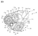
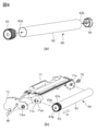
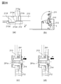
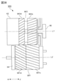
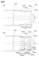
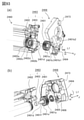
- FIG. 3 is a cross-sectional view of the cartridge.
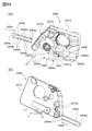
- FIG. 4 is an exploded perspective view of the cartridge.
- FIG. 5 is an exploded perspective view of the cartridge.
- FIG. 6 is an exploded perspective view of the cleaning unit.
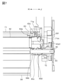
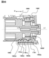
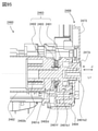
- FIG. 7 is a cross-sectional view of a drive unit from the main body of the device to the cartridge.
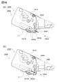
- FIG. 8 is a cross-sectional view of the main body of the device.
- FIG. 9 is a cross-sectional view of the main body of the device.
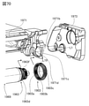
- FIG. 10 is a cross-sectional view of the main body of the device.
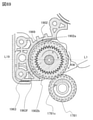
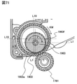
- FIG. 11 is an exploded perspective view of the main body of the device.
- FIG. 12 is a perspective view of the drive transmission unit of the main body of the apparatus.
- FIG. 13 is a schematic diagram of the drive transmission gear of the main body of the device.
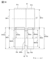
- FIG. 14 is a schematic diagram of a drive transmission configuration from the drive transmission gear to the drive side flange.
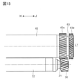
- FIG. 15 is a diagram showing a drive transmission configuration from the drive side flange to the developing roller.
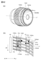
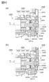
- FIG. 16 is a schematic view of the drive transmission gear and the drive side flange, and a cross-sectional view of the drive transmission gear.
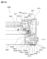
- FIG. 17 is a cross-sectional view of the drive transmission gear and the drive side flange.
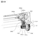
- FIG. 22 is a diagram showing a drive transmission gear and a drive side flange.
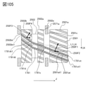
- FIG. 25 is a diagram showing a drive transmission configuration.
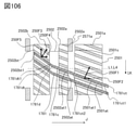
- FIG. 26 is a cross-sectional view of the drive transmission unit.
- FIG. 31 is a cross-sectional view of the drive transmission gear and the drive side flange.
- FIG. 35 is a perspective view of the drive side flange.
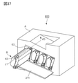
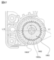
- FIG. 37 is a perspective view of the image forming apparatus.
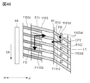
- FIG. 40 is a cross-sectional view of the drive transmission gear and the drive side flange.
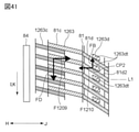
- FIG. 41 is a cross-sectional view of the drive transmission gear and the drive side flange.
- FIG. 42 is a perspective view of the drive side flange, and a cross-sectional view of the drive transmission gear and the drive side flange.
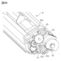
- FIG. 44 is a partial perspective view of the cartridge.
- FIG. 45 is a partial cross-sectional view of the vicinity of the drum of the cartridge, and is a diagram showing the drum and the developing roller.
- FIG. 47 is a schematic diagram of the drive transmission gear and the drive side flange.
- FIG. 48 is a cross-sectional view of the drive side flange, and a cross-sectional view of the drive transmission gear and the drive side flange.
- FIG. 49 is a graph showing a drive transmission error at the time of misalignment.
- FIG. 50 is a schematic cross-sectional view of the main body of the device and the cartridge.
- FIG. 52 is a perspective view of the drum bearing member, a cross-sectional view of the drive side flange and the drum bearing member, and a partial cross-sectional view of the cartridge.
- FIG. 55 is a schematic cross-sectional view of the gear portion of the drive transmission gear and the gear portion of the drive side drum flange.
- FIG. 56 is a perspective view of a drive train that drives a developing roller, a partial perspective view of a developing unit, and a perspective view of a cartridge.
- FIG. 57 is a partial perspective view of the main body of the device.
- FIG. 58 is a cross-sectional view of the cleaning unit and the drive transmission gear.
- FIG. 59 is a partial perspective view of the cartridge.
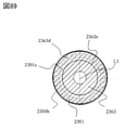
- FIG. 60 is a cross-sectional view of the drum unit.
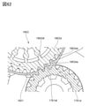
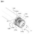
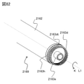
- FIG. 61 is a partial perspective view of the drum unit.
- FIG. 62 is a cross-sectional view of the second gear portion and the second main body gear portion.
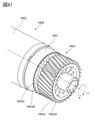
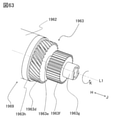
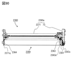
- FIG. 63 is a partial perspective view of the drum unit.
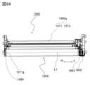
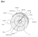
- FIG. 64 is a side view of the cleaning unit.
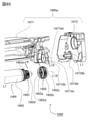
- FIG. 65 is an exploded perspective view of the cleaning unit.
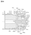
- FIG. 66 is a partial cross-sectional view of the cleaning unit.
- FIG. 67 is a partial cross-sectional view of the cleaning unit.
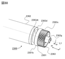
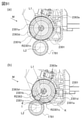
- FIG. 68 is a cross-sectional view showing an engaged state between the drum unit and the drive transmission gear.
- FIG. 69 is a cross-sectional view showing an engaged state between the drum unit and the drive transmission gear.
- FIG. 70 is an exploded perspective view of the cleaning unit.
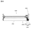
- FIG. 72 is a partial perspective view of the drum unit.
- FIG. 74 is a diagram showing a drum unit that meshes with the drive transmission gear.
- FIG. 78 is a cross-sectional view of the cleaning unit.
- FIG. 79 is a cross-sectional view showing an engaged state between the drum unit and the drive transmission gear.
- FIG. 80 is a cross-sectional view showing an engaged state between the drum unit and the drive transmission gear.
- FIG. 81 is a partial perspective view of the drum unit.
- FIG. 82 is a partial perspective view of the drum unit.
- FIG. 85 is a diagram showing a state in which the drum unit is assembled to the cleaning unit.
- FIG. 87 is a cross-sectional view of the drive side flange and the drive transmission gear.
- FIG. 97 is a partial cross-sectional view of the cleaning unit.
- FIG. 100 is a schematic cross-sectional view of the meshing portion between the drive side drum flange and the drive transmission gear.
- FIG. 102 is an exploded perspective view of the cleaning unit and the drum unit.
- FIG. 108 is an exploded perspective view of the cleaning unit and the drum unit.
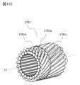
- FIG. 112 is a perspective view of another configuration example of the drive transmission gear.
- FIG. 113 is a diagram showing a cartridge.
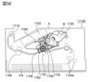
- FIG. 2 is a cross-sectional view of the electrophotographic image forming apparatus (image forming apparatus) 100, and the cross section thereof is a cross section orthogonal to the rotation axis L1 of the photosensitive drum 62 described later.
- the image forming apparatus 100 is a laser beam printer using electrophotographic technology, and a cartridge B including a photosensitive drum 62 is detachably attached to the apparatus main body A. That is, the portion of the image forming apparatus 100 excluding the cartridge B is the apparatus main body A.
- a recording medium (sheet material) PA such as paper.
- the apparatus main body A has an exposure apparatus (laser scanner unit) 3 and a sheet tray 4 for accommodating the sheet material PA. Further, the apparatus main body A includes a pickup roller 5a, a transfer roller pair 5b, a transfer guide 6, a transfer roller 7, a transfer guide 8, a fixing device 9, a discharge roller pair 10, and a discharge tray along the transport direction D of the sheet material PA. Has 11.
- the fixing device 9 includes a heating roller 9a and a pressure roller 9b.
- Cartridge B is a process cartridge and mainly has an electrophotographic photosensitive member and a process means acting on the electrophotographic photosensitive member.
- the process means are charging means, developing means and cleaning means described later.
- the cartridge B has a structure mainly having a cleaning unit (drum unit) 60 and a developing unit 20, and the electrophotographic photosensitive member and the process means are provided in these cleaning unit 60 or the developing unit 20.
- the cleaning unit (drum unit) 60 includes a photosensitive drum 62, a charging roller 66, a cleaning member 77, and a cleaning frame body (drum frame body) 60a that supports them.
- the cleaning frame body (drum frame body) 60a includes a frame body member 71 and a drum bearing member 73.
- the cleaning unit 60 may be referred to as a drum unit.
- the drum 62 is paired with the developing unit 20 having a developing means when the contents of the cartridge B are roughly recognized. It is a name when the entire cleaning unit 60 is recognized as a unit to have. Therefore, the drum unit as a name of the entire cleaning unit 60 is a different concept from the drum unit 69 (a unit that can rotate integrally with the drum 62) in this embodiment. In the following description, the drum unit refers to a unit that can rotate integrally with the drum 62.
- the drum 62, the drive side flange 63, and the non-drive side flange 64 rotate integrally around the rotation axis L1 of the drum. That is, the rotation axes of the drive side flange 63, the non-drive side flange 64, and the drum unit 69 are coaxial with the rotation axis L1 of the drum 62. Therefore, hereinafter, the rotation axes of the drum 62, the drive side flange 63, the non-drive side flange 64, and the drum unit 69 in the assembled drum unit 69 are all referred to as rotation axes L1.
- the drive side flange 63 and the non-drive side flange 64 are integrally fixed with respect to the direction of the rotation axis L1.
- the drive-side flange 63 and the non-drive-side flange 64 are resin members.
- the drive-side flange 63 includes a first gear portion 63c and a second gear portion 63d, which will be described in detail later.
- the drum unit 69 is rotatably supported around the rotation axis L1 by the drum frame body 60a (frame body member 71 and drum bearing member 73).
- the drive side flange 63 is provided with a hole 63 g coaxial with the rotation axis L1, and the shaft member 86 press-fitted into the drum bearing member 73 is inserted into the hole 63 g, whereby the shaft member 86 rotates in the drum bearing member 73. It is supported as much as possible.
- the non-driving side flange 64 has a hole (not shown) coaxial with the rotation axis L1, and the shaft member 78 press-fitted into the hole 71c of the frame body member 71 is inserted into this hole, whereby the frame body member 71 is inserted. It is rotatably supported. As described above, the non-driving side flange 64 and the driving side flange 63 are bearing portions rotatably supported by the shaft members 86 and 78.
- the second gear portion 63d of the drive side flange 63 includes a protruding portion 63d1 protruding in the H direction on the end surface on the downstream side in the H direction, and is on the upstream side in the H direction (downstream side in the J direction).
- the end face is provided with a protruding portion 63f protruding in the J direction.
- the frame body member 71 includes a rib 71p and a side wall 71m provided so as to extend in a direction orthogonal to the rotation axis L1.
- the protrusion 63d1 is in contact with the side surface of the rib 71p, and the protrusion 63f is in contact with the side surface of the side wall 71m.
- the drive side flange 63 is slidably fitted between the rib 71p and the side wall 71m by fitting a gap. Therefore, there may be a case where the protruding portion 63d1 contacts the side surface of the rib 71p and a case where the protruding portion 63f contacts the side surface of the side wall 71m, but the fitting backlash (gap) is extremely small (up to about 150 ⁇ m). It can be said that they are set and are positioned at substantially the same position in both cases. As described above, it can be said that the drum unit 69 including the drive side flange 63 is positioned in the direction of the rotation axis L1 with respect to the drum frame body 60a by the rib 71p or the side wall 71m.
- the longitudinal direction of the cartridge B, the drum frame body 60a, and the frame body member 71 is a direction parallel to the direction of the rotation axis L1 of the drum 62.
- the charging roller (charging member) 66 as the charging means and the cleaning member 77 as the cleaning means are arranged in contact with the outer peripheral surface of the drum 62, respectively.
- the cleaning member 77 includes a rubber blade 77a, which is a blade-shaped elastic member made of rubber as an elastic material, and a support member 77b that supports the rubber blade 77a.
- the rubber blade 77a is in contact with the drum 62 in the counter direction with respect to the rotation direction of the drum 62. That is, the rubber blade 77a is in contact with the drum 62 so that its tip end faces the upstream side in the rotation direction of the drum 62.
- waste toner removed from the surface of the drum 62 by the cleaning member 77 is stored (stored) in the waste toner chamber 71b formed by the frame member 71 and the cleaning member 77.
- a sheet 65 for suppressing the leakage of waste toner from the gap between the frame member 71 and the drum 62 is attached to the edge of the frame member 71 so as to abut on the drum 62.
- Both ends of the charging roller 66 in the direction of the rotation axis are rotatably supported by the charging roller bearing 67 supported by the frame member 71.
- the rotation axis of the charging roller 66 is substantially parallel to the rotation axis L1 of the drum 62.
- the charging roller 66 is pressed against the drum 62 by pressing the charging roller bearing 67 toward the drum 62 by the urging member 68.
- the charging roller 66 is driven by the rotation of the drum 62.
- the developing unit 20 includes a developing roller 32, a magnet roller 34, a developing blade 42, a transport member 43, a developing frame body 20a that supports them, and the like.
- the developing frame 20a includes a developing container 23, a bottom member 22, a bearing member 24 (see FIG. 5), a bearing member 37 (see FIG. 4), a developing side cover 26 (see FIG. 4), and a developing side cover 27 (see FIG. 5). ).
- a toner supply chamber 28 and a toner chamber 29 are formed inside by a developing container 23 and a bottom member 22.
- both ends of the developing roller 32 in the rotation axis direction are rotatably supported by the bearing member 24 and the bearing member 37.
- the bearing member 24 and the bearing member 37 are attached to the developing container 23.
- the developing roller (developing member) 32 as a developing means is a cylindrical member, and a magnet roller 34 is arranged inside the cylindrical member.
- a developing blade 42 that regulates (regulates) the thickness of the toner (toner layer) supported on the surface of the developing roller 32 is arranged.
- Spacing members 38 are attached to both ends of the developing roller 32 in the direction of the rotation axis, and when the spacing members 38 abut on the surface of the drum 62, the surface of the developing roller 32 with respect to the surface of the drum 62 The distance is decided. Specifically, the distance is determined so that a minute gap is formed between the surface of the developing roller 32 and the surface of the drum 62.
- the edge portion of the bottom member 22 is such that the sheet 33 for preventing toner from leaking from the gap between the developing frame body 20a and the developing roller 32 abuts on the developing roller 32. It is attached to. Further, in the toner chamber 29, a transport member (stirring member) 43 is rotatably provided. The transport member 43 rotates to stir the toner contained in the toner chamber 29, and transports the toner from the toner chamber 29 to the toner supply chamber 28. ⁇ Combining the cleaning unit and the developing unit>
- Cartridge B is assembled by combining the cleaning unit 60 and the developing unit 20.
- FIGS. 4 and 5 first, development of the developing container 23 with respect to the first hanging hole 71i on the driving side of the frame body member 71. Align the center of the second support boss 27a. Then, by moving the developing unit 20 in the direction of the arrow G, the developing first supporting boss 26a and the developing second supporting boss 27a are fitted into the first hanging hole 71i and the second hanging hole 71j. After that, by assembling the drum bearing member 73 to the cleaning unit 60, the developing unit 20 is restricted from being separated from the cleaning unit 60. As a result, the developing unit 20 is movably connected to the cleaning unit 60. Specifically, the developing unit 20 is rotatably (rotatably) connected to the cleaning unit 60 around the developing first supporting boss 26a and the developing second supporting boss 27a.
- the first end portion 46Rb of the drive side spring (urging member) 46R is fixed to the surface 26b of the developing side cover 26, and the second end portion 46Ra is the frame member 71 of the cleaning unit 60. Abuts on the surface 71k.
- the first end portion 46Lb of the non-driving side spring (urging member) 46L is fixed to the surface 27b of the developing side cover 27, and the second end portion 46La is the surface 71l of the frame body member 71.
- the non-drive side spring 46L and the drive side spring 46R are compression springs.
- a control unit receives a print command signal sent from a host computer or the like, and generates a print start signal based on the print command signal to start the image forming process.
- the drum 62 is first rotationally driven in the arrow R direction (see FIGS. 2 and 3) at a predetermined peripheral speed (process speed).
- a charging bias voltage is applied to the charging roller 66 to substantially uniformly charge the surface (outer peripheral surface) of the drum 62.
- the exposure apparatus (exposure means) 3 emits a laser beam L according to the image information to be printed.
- the laser beam L passes through the laser opening 71h provided in the frame member 71 of the cartridge B, irradiates the surface of the drum 62 charged by the charging roller 66, and scans the surface of the drum 62 with the laser beam L.
- an electrostatic latent image corresponding to the image information is formed on the photosensitive layer on the surface of the drum 62.
- the toner (developer) T in the toner chamber 29 is agitated and conveyed by the rotation of the conveying member 43, and is sent out to the toner supply chamber 28.
- the toner T is supported on the surface of the developing roller 32 by the magnetic force of the magnet roller (fixed magnet) 34.
- the developing roller 32 is a developer carrier that supports the toner T on its surface, and the electrostatic latent image formed on the drum 62 described above is visualized (developed) with the toner.
- the toner T is triboelectrically charged by the developing blade 42, and the developing blade 42 regulates the thickness (layer thickness) of the layer of the toner T on the peripheral surface of the developing roller 32 so as to be a desired thickness.
- the toner T supported on the surface of the developing roller 32 is supplied to and adheres to the region corresponding to the electrostatic latent image of the drum 62.
- the electrostatic latent image on the drum 62 is visualized (developed) as a toner image.
- the drum 62 is an image carrier that carries an electrostatic latent image or a toner image (developer image) on its surface.
- the sheet material PA stored in the seat tray 4 at the lower part of the apparatus main body A is subjected to the apparatus main body by the pickup roller 5a and the transport roller pair 5b. It is sent out to the transport path in A.
- the sheet material PA is guided by the transfer guide 6 and conveyed to the transfer nip between the drum 62 and the transfer roller (transfer means) 7. In this transfer nip, the toner image formed on the drum 62 is transferred onto the sheet material PA.
- the sheet material PA that has passed through the transfer nip and has the toner image transferred is guided by the transport guide 8 and transported to the fixing device (fixing means) 9. Then, the sheet material PA passes through the fixing nip between the heating roller 9a and the pressure roller 9b of the fixing device 9. By pressurizing and heating the sheet material PA with this fixing nip, the toner image is fused to the sheet material PA and fixed.
- the sheet material PA that has passed through the fixing nip is conveyed to the discharge roller pair 10 and discharged onto the discharge tray 11.
- the surface of the drum 62 after passing through the transfer nip comes into contact with the cleaning blade 77, the toner remaining on the surface of the drum 62 is removed, and the surface of the drum 62 can be used again in the above-mentioned image forming process. It will be like.
- the toner removed from the drum 62 by the cleaning blade 77 is stored as waste toner in the waste toner chamber 71b of the cleaning unit 60.
- At least the charging roller 66, the exposure apparatus 3, the developing roller 32, the transfer roller 7, and the cleaning blade 77 are process means acting on the drum 62. ⁇ Installation and removal of cartridges>
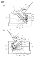
- FIG. 8A is a cross-sectional view of the drive side of the device main body A with the door 13 open
- FIG. 8B is a cross-sectional view of the non-drive side of the device main body A with the door 13 open.
- the cross section shown in FIGS. 8 (a) and 8 (b) is a cross section orthogonal to the rotation axis L1.
- FIG. 9 is a diagram for explaining positioning of the cartridge B in the longitudinal direction (direction of the rotation axis L1), and the fitting portion 15j of the apparatus main body A is a horizontal plane parallel to the rotation axis L1 (installation surface of the apparatus main body A).
- FIG. 9A shows a state immediately before the cartridge B is fitted to the fitting portion 15j
- FIG. 9B shows a state in which the cartridge B is fitted to the fitting portion 15j
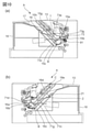
- 10 (a) is a cross-sectional view of the drive side of the device main body A with the door 13 closed
- FIG. 10 (b) is a cross-sectional view of the non-drive side of the device main body A with the door 13 closed. Is.
- the cross section shown in FIGS. 10 (a) and 10 (b) is a cross section orthogonal to the rotation axis L1.
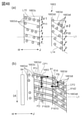
- the apparatus main body A is provided with a first drive side plate 15 and a non-drive side plate 16 so as to sandwich the cartridge B mounted on the apparatus main body A in the direction of the rotation axis L1. Further, a door 13 for opening and closing the insertion port 17 is rotatably attached to the apparatus main body A.
- the first drive side plate 15 has an upper guide rail 15g and a lower guide rail 15h that guide the cartridge B when the cartridge B is mounted and removed.
- the non-driving side plate 16 has an upper guide rail 16d and a lower guide rail 16e that guide the cartridge B when the cartridge B is mounted and removed.
- the drum bearing member 73 of the cartridge B is provided with a guided portion 73g and a rotated stop portion 73c, and the frame body member 71 has a positioned portion 71d and a rotated stop portion 71g. Therefore, the guided portion 73g and the rotated stop portion 73c are arranged on the drive side of the cartridge B, and the guided portion 73g and the rotated stop portion 73c are arranged on the non-driven side of the cartridge B.
- the cartridge B When the door 13 of the apparatus main body A is opened and the insertion port 17 formed between the first drive side plate 15 and the non-drive side plate 16 is open, the cartridge B is inserted into the apparatus main body through the insertion opening 17. It can be inserted or removed from A. At this time, by moving the cartridge B in a direction substantially orthogonal to the rotation axis L1 of the drum 62, the cartridge B can be inserted and mounted on the apparatus main body A and removed from the apparatus main body A. That is, the mounting direction M of the cartridge B to the device main body A (FIG. 9A) and the removing direction from the device main body A (reverse direction of the mounting direction M) are directions substantially orthogonal to the rotation axis L1. be.
- the cartridge B Since the rotation axis L1 of the cartridge B mounted on the device main body A is parallel to the rotation axis L2 of the drive transmission gear 81, the cartridge B is mounted in the device body A from the mounting direction M and the device body A. It can be said that the removal direction of is substantially orthogonal to the rotation axis L2. Further, when the cartridge B is attached to and detached from the apparatus main body A, the drum unit 69 moves integrally with the cartridge B to the apparatus main body A, and is attached to and detached from the apparatus main body A. ..
- the mounting direction of the drum unit 69 to the device main body A and the removing direction from the device main body A are the same as the mounting direction M of the cartridge B to the device main body A and the removing direction from the device main body A, respectively.
- the guided portion 73g and the rotated stop portion 73c on the drive side of the cartridge B are connected to the upper guide rail 15g and the guide rail 15h. Each will be guided.
- the non-driven side positioned portion 71d and the rotated stop portion 71g of the cartridge B are guided by the upper guide rail 16d and the lower guide rail 16e.
- the drum bearing member 73 serves as a positioned portion (axis direction positioned portion) positioned with respect to the apparatus main body A with respect to the direction of the rotation axis L1. It has a fitted portion 73h.
- the fitted portion 73h has a concave shape (or a groove shape or a slit shape) recessed in the mounting direction M (direction orthogonal to the rotation axis L1).
- the first drive side plate 15 of the apparatus main body A has a fitting portion 15j that can be fitted with the fitted portion 73h.
- the fitting portion 15j has a convex shape protruding in the direction opposite to the mounting direction MD.
- the fitted portion 73h is fitted with the fitting portion 15j, so that the direction of the rotation axis L1 of the cartridge B (cartridge B). Position in the longitudinal direction of) is determined.
- the fitting portion 73h and the fitting portion 15j are fitted in a gap, but the fitting backlash (gap) is set to be extremely small (up to about 150 ⁇ m). Therefore, it can be said that the cartridge B is positioned at substantially the same position with respect to the direction of the rotation axis L1 regardless of whether the fitted portion 73h abuts on the fitting portion 15j in either the H direction or the J direction.
- the first drive side plate 15 has a positioning portion 15a, a positioning portion 15b, and a rotation stop portion 15c.
- the non-driving side plate 16 has a positioning portion 16a, a positioning portion 16b, and a rotation stop portion 16c.
- Cartridge pressing members 1 and 2 are attached to both ends of the door 13 in the direction of the rotation axis of the door 13 so as to be movable (rotatable) with respect to the door 13. Further, the pressing springs 19 and 21 are attached to the first drive side plate 15 and the non-drive side plate 16, respectively.
- the drum bearing member 73 of the cartridge B has a pressed portion (urging force receiving portion) 73e
- the frame body member 71 has a pressed portion (urging force receiving portion) 71n. ..
- the pressed portions 73e and 71n are provided in concave portions arranged on the drive side and the non-drive side of the cartridge B, respectively.
- the cartridge pressing members 1 and 2 are urged toward the cartridge B by the pressing springs 19 and 21. Then, the cartridge pressing members 1 and 2 abut on the pressed portions 73e and 71n, and press the pressed portions 73e and 71n by the urging force of the pressing springs 19 and 21.
- the positioned portion 73g of the cartridge B comes into contact with the positioning portion 15a and the positioning portion 15b of the device main body A, and the rotation stop portion 73c comes into contact with the rotation stop portion 15c of the device main body A.
- positioning of the drive-side portion of the drum frame 60a of the cartridge B in a direction orthogonal to the rotation axis L1 and rotation around the axis parallel to the rotation axis L1 are restricted.
- the positioned portion 71d of the cartridge B abuts on the positioning portions 16a and 16b of the device main body A, and the rotated stop portion 71g abuts on the rotation stop portion 16c of the device main body A.
- positioning of the non-driving side portion of the drum frame 60a of the cartridge B in the direction orthogonal to the rotation axis L1 and rotation around the axis parallel to the rotation axis L1 are restricted.
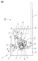
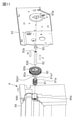
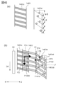
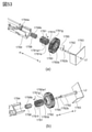
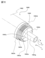
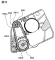
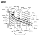
- FIG. 1 is a perspective view of a portion of a portion driven and transmitted from the apparatus main body A to the drum unit 69.
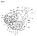
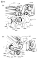
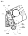
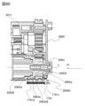
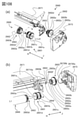
- FIG. 11 is an exploded perspective view showing a support configuration of the drive transmission gear 81 of the apparatus main body A.
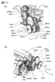
- FIG. 12 is a perspective view showing a drive transmission unit of the apparatus main body A.
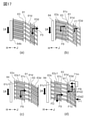
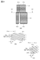
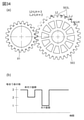
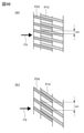
- FIG. 13A is a diagram schematically showing the drive transmission gear 81 of the apparatus main body A.
- FIG. 13B is a diagram schematically showing the drive side flange 63 of the cartridge B.
- the ridgeline of the tooth tip is shown for the gear tooth.
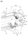
- FIG. 14 is a diagram schematically showing a drive transmission configuration from the drive transmission gear 81 of the apparatus main body A to the cartridge B to the drive side flange 63.
- the apparatus main body A includes a motor (not shown), an idler gear 80, a drive transmission gear 81, a second drive side plate 83, a main frame body 84, a drive shaft 82, and a compression spring 85.
- the driving force from the motor is transmitted from the idler gear 80 to the drive transmission gear 81.
- the idler gear 80 and the drive transmission gear 81 are supported by the drive shaft 82 so as to be coaxial with each other and movably movable in the direction of the rotation axis.
- One end 82a of the drive shaft 82 is fixed to the hole 83a of the second drive side plate 83, and the other end 82b is supported by the hole 84a of the main frame 84.
- the drive shaft 82 is provided so that the rotation axis of the drive transmission gear 81 is parallel to the rotation axis L1 of the drum 62 when the cartridge B is mounted on the apparatus main body A.
- a compression spring 85 is provided between the other end 80b of the idler gear 80 and the second drive side plate 83, and the idler gear 80 is urged in the H direction in the rotation axis direction.
- the J direction and the H direction in the apparatus main body A are defined to coincide with the J direction and the H direction of the cartridge B mounted on the apparatus main body A.
- the J direction is the direction from the idler gear 80 toward the second drive side plate 83 along the rotation axis of the idler gear 80
- the H direction is the opposite direction.
- One end 80a of the idler gear 80 is provided with a recess 80a1 recessed in the direction of the rotation axis.
- one end 81a of the drive transmission gear 81 is provided with a protrusion 81a1 protruding in the direction of the rotation axis at a position facing the recess 80a1 of the idler gear 80.
- the drive transmission gear 81 meshes with the drive side flange 63 of the cartridge B to transmit the drive force.
- the drive transmission gear 81 is performing the above-mentioned image forming process, the initial operation after mounting the cartridge B, and the preparatory operation of the image forming process (collectively referred to as “driving”). Rotates in the I direction, and the drive side flange 63 rotates in the K direction. That is, the driving direction (rotation direction) of the drive transmission gear 81 during driving is the I direction, and the driving direction (rotation direction) of the drive side flange 63 during driving is the K direction. Looking at the drive transmission gear 81 and the drive side flange 63 from the drive side to the non-drive side along the H direction, the I direction is the clockwise direction and the K direction is the counterclockwise direction. ⁇ Drive transmission gear 81>
- the drive transmission gear 81 is a first main body gear portion (first main body side gear portion, first main body side oblique tooth gear portion) as an oblique tooth gear portion.
- 81c and a second main body gear portion (second main body side gear portion, second main body side oblique tooth gear portion) 81d are provided coaxially.
- the first main body gear portion 81c is arranged on the downstream side in the H direction (upstream side in the J direction) with respect to the second main body gear portion 81d.
- the first main body gear portion 81c includes a plurality of first main body oblique teeth 81ct
- the second main body gear portion 81d includes a plurality of second main body oblique teeth 81dt.
- the first main body oblique tooth 81ct and the second main body oblique tooth 81dt are both involute tooth profiles.
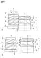
- the first main body gear portion 81c and the second main body gear portion 81d are integrally molded with resin and rotate integrally. Further, the twisting direction of the first main body gear portion 81c and the second main body gear portion 81d is the same direction as each other, and the tooth surface is twisted so as to be displaced toward the I direction toward the J direction. Further, as shown in FIG.
- the helix angle ⁇ 2 of the second main body gear portion 81d is larger than the helix angle ⁇ 1 of the first main body gear portion 81c (that is, ⁇ 1 ⁇ 2 is satisfied). Further, the number of teeth of the first main body gear portion 81c and the second main body gear portion 81d are the same. ⁇ Drive side flange 63>
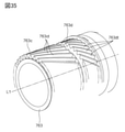
- the drive side flange 63 is a first gear portion (first unit side gear portion, first unit side oblique) as an oblique tooth gear portion.
- a tooth gear portion (first oblique tooth gear portion) 63c and a second gear portion (second unit side gear portion, second unit side oblique tooth gear portion, second oblique tooth gear portion) 63d are coaxially provided.
- the first gear portion 63c is arranged on the downstream side in the H direction (upstream side in the J direction) with respect to the second gear portion 63d.
- the first gear portion 63c is arranged between the second gear portion 63d and the drum 62 with respect to the direction of the rotation axis L1.
- the first gear portion 63c includes a plurality of first oblique teeth (first protrusions) 63ct arranged at different positions in the circumferential direction about the rotation axis L1, and the second gear portion 63d is centered on the rotation axis L1.
- the first oblique tooth 63ct and the second oblique tooth 63dt are both involute teeth and are protrusions protruding in the radial direction about the rotation axis L1.
- the first gear portion 63c and the second gear portion 63d are integrally molded with resin and rotate integrally. Therefore, the first gear portion 63c and the second gear portion 63d are the first rotating portions that rotate integrally with each other. , It can also be regarded as the second rotating part.
- the first gear portion 63c meshes with the first main body gear portion 81c of the drive transmission gear 81
- the second gear portion 63d meshes with the second main body gear portion 81d of the drive transmission gear 81.
- the twisting directions of the first gear portion 63c and the second gear portion 63d of the drive side flange 63 are the same as each other, and the tooth surface is displaced toward the K direction as the J direction is reached. It is a twisting direction.
- the twisting direction of the first gear portion 63c and the second gear portion 63d is opposite to the twisting direction of the first main body gear portion 81c and the second main body gear portion 81d of the drive transmission gear 81.
- the helix angle ⁇ 2 of the second gear portion 63d is larger than the helix angle ⁇ 1 of the first gear portion 63c (that is, ⁇ 1 ⁇ 2 is satisfied).
- the helix angle ⁇ 1 of the first gear portion 63c is the same as the helix angle ⁇ 1 of the first main body gear portion 81c, and the helix angle ⁇ 2 of the second gear portion 63d is the same as the helix angle ⁇ 2 of the second main body gear portion 81d. be. Further, the number of teeth of the first gear portion 63c and the second gear portion 63d of the drive side flange 63 is the same.
- the width (tooth width) W63c (Wc, Wc1) of the first oblique tooth (first protrusion) 63 ct in the direction of the rotation axis L1 is the width of the second oblique tooth (second protrusion) 63 dt in the direction of the rotation axis L1.
- a tooth having a tooth width Wd of 63 dt satisfying the following formula A1 is provided at least one tooth at a time.
- the width (tooth width) of the first oblique tooth 63ct which has the widest width (tooth width) in the direction of the rotation axis L1 of the first gear portion 63c, is Wc1
- the second gear portion 63d is the rotation axis. It has a second oblique tooth (second protrusion) 63 dt whose width (tooth width) in the direction of L1 is smaller than that of Wc1.
- the driving force FD received by the first gear portion 1763c is higher than the regulatory force FB received by the second gear portion 1763d. Therefore, it is preferable to have such a relationship.
- the width (meshing width) of the rotation axis L1 of the portion where the first gear portion 63c meshes (contacts) with the first main body gear portion 81c and the meshing of the second oblique tooth gear portion 63c with the second main body gear portion 81d The larger the width, the better the drive transmission accuracy. However, if the meshing width is set larger than necessary, the width of the first gear portion 63c and the second gear portion 63c in the direction of the rotation axis L1 becomes large, and the drive side flange 63, the drum unit 69, the cartridge B, and eventually the apparatus main body A Will become larger.
- the tooth width Wc1 of the first oblique tooth (teeth) 63ct having the widest tooth width in the first gear portion 63c and the second oblique tooth (teeth) 63dt having the widest tooth width in the second gear portion 63d The tooth width Wd1 preferably satisfies the following formula A2, more preferably formula A3. Wd1 ⁇ (4/5) ⁇ Wc1 ... (Equation A2) Wd1 ⁇ (3/4) ⁇ Wc1 ... (Equation A3)
- the second oblique tooth (teeth) 63 dt has a tooth width of a certain level or more, and the tooth width Wc1 and the tooth width. It is preferable that Wd1 satisfies the following formula A4. Wd1 ⁇ (1/10) ⁇ Wc1 ... (Equation A4)
- the meshing pitch circle diameters D63c and D63d of the first gear portion 63c and the second gear portion 63d in the meshing between the drive side flange 63 and the drive transmission gear 81 are set to be substantially the same. is doing. Further, the tooth tip circle diameters Dt63c and Dt63d of the first gear portion 63c and the second gear portion 63d are also set to be substantially the same. Similarly, the meshing pitch circle diameters D81c and D81d of the first main body gear portion 81c and the second main body gear portion 81d are set to be substantially the same. As a result, the meshing of the first gear portion 63c and the first main body gear portion 81c and the meshing of the second gear portion 63d and the second main body gear portion 81d can be appropriately meshed without hitting the tooth tips. can.
- the shapes of the first gear portion 63c and the second gear portion 63d are as follows. It is preferable to decide.
- the size of the tip circle diameter Dt63c of the first gear portion 63c is a value larger than the tooth bottom circle diameter Db63d of the second gear portion 63d, or the tooth tip circle diameter Dt63d of the second gear portion 63d. It is preferable to set a value larger than 0.8 times (more preferably 0.9 times). Further, the size of the tooth tip circle diameter Dt63c of the first gear portion 63c is preferably set to a value smaller than 1.1 times the tooth tip circle diameter Dt63d of the second gear portion 63d.
- the size of the tooth bottom circle diameter Db63c of the first gear portion 63c is set to a value smaller than the tooth tip circle diameter Dt63d of the second gear portion 63d. Further, the size of the tooth bottom circle diameter Db63c of the first gear portion 63c is preferably set to a value larger than 0.9 times the tooth bottom circle diameter Db63d of the second gear portion 63d.
- the size of the tooth tip circle diameter Dt63d of the second gear portion 63d is a value larger than the tooth bottom circle diameter Db63c of the first gear portion 63c, or 0.8 of the tooth tip circle diameter Dt63c of the first gear portion 63c. It is preferable to set a value larger than double (more preferably 0.9 times). Further, the size of the tooth tip circle diameter Dt63d of the second gear portion 63d is preferably set to a value smaller than 1.1 times the tooth tip circle diameter Dt63c of the first gear portion 63c.
- the size of the tooth bottom circle diameter Db63d of the second gear portion 63d is set to a value smaller than the tooth tip circle diameter Dt63c of the first gear portion 63c. Further, the size of the tooth bottom circle diameter Db63d of the second gear portion 63d is preferably set to a value larger than 0.9 times the tooth bottom circle diameter Db63c of the first gear portion 63c.
- the relationship between these dimensions is shown using the diameters of the first gear portion 63c and the second gear portion 63d, but it is obvious that the relationship is the same even if the diameter is replaced with a radius.
- the tip circle is a circle drawn as a rotation locus when the tip (point) farthest from the rotation axis L1 among the tips of the plurality of protrusions rotates, and the diameter / radius of this circle is the tip circle diameter. / The radius of the tip of the circle.
- a module is used between the first gear portion 63c and the second gear portion 63d. And the amount of metastasis is changed. Similarly, for the drive transmission gear 81, the modules are different between the first main body gear portion 81c and the second main body gear portion 81d, and the transfer amount is changed.
- the drive side flange 63 includes a cylindrical portion (intermediate portion, small diameter portion, shaft portion) 63e between the first gear portion 63c and the second gear portion 63d in the direction of the rotation axis L1.
- the maximum diameter D63e centered on the rotation axis L1 of the cylindrical portion 63e is smaller than the tip circle diameter Dt63c of the first gear portion 63c and the tooth tip circle diameter Dt63d of the second gear portion 63d.
- the maximum diameter D63e centered on the rotation axis L1 of the cylindrical portion 63e is smaller than the tooth bottom circle diameter Db63c of the first gear portion 63c and the tooth bottom circle diameter Db63d of the second gear portion 63d.
- the maximum diameter D63e centered on the rotation axis L1 of the cylindrical portion 63e is not limited to the above unless it comes into contact with the drive transmission gear 81 while the drive side flange 63 is being driven by the drive transmission gear 81. Further, as will be described later in Examples 22 and 23, from the rotary axis L1 to the outer diameter of the cylindrical portion 63e so that the drive side flange 63 and the drive transmission gear 81 can mesh with each other to transmit the drive force.
- the distance (radius) R63e may be configured to be at least temporarily smaller than the tip circle radius Rt63ct of the first gear portion 63c or the tip circle radius Rt63d of the second gear portion 63d.
- the shape of the cylindrical portion 63e does not have to be a cylindrical shape centered on the rotation axis L1.
- it is possible to make various shapes such as a polygonal prism shape and a shape that is not symmetrical with respect to the rotation axis L1.
- the diameter of the circle drawn as the rotation locus at the point farthest from the rotation axis L1 in the intermediate portion 63e is the above-mentioned maximum diameter D63e, and the radius of the circle is the radius R63e. Is the maximum value of.
- the second gear portion 63d can be arranged at a position away from the drum 62 (more downstream side in the J direction) so as not to come into contact with the first gear portion 81c.
- the first gear portion 63c can be arranged at a position close to the drum 62 (more downstream in the H direction) so as not to come into contact with the second main body gear portion 81d. That is, by providing the cylindrical portion 63e, a gap g is formed between the first gear portion 81c and the second gear portion 63d in the direction of the rotation axis L1.
- the first gear portion 63c comes into contact with the second main body gear portion 81d with respect to the direction of the rotation axis L1, and the second gear portion 63d is the first main body gear. It is possible to prevent contact with the portion 81c. Further, when the drive transmission gear 81 is driven and the drive transmission gear 81 is moved to the balanced position, the first main body gear portion 81c comes into contact with the second gear portion 63d, and the second main body gear portion 81d It is possible to prevent contact with the first gear portion 63c.
- the width of the cylindrical portion 63e in the direction of the rotation axis L1 will be described in detail below. ⁇ Drive transmission to the developing roller>
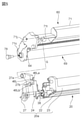
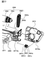
- FIG. 15 is a diagram showing a drive transmission configuration from the drive side flange 63 to the developing roller 32.
- the developing roller 32 is fixed to the developing roller shaft 31, and a developing roller gear 30 is provided at one end on the drive side of the developing roller shaft 31 so as to be movable in the direction of the rotation axis of the developing roller shaft 31.
- the developing roller gear 30 can rotate integrally with the developing roller shaft 31 and the developing roller 32. That is, the developing roller gear 30 is provided so as to be able to drive and transmit to the developing roller shaft 31 and the developing roller 32.
- the developing roller gear 30 meshes with the first gear portion 63c of the drive side flange 63 to transmit the driving force.
- the developing roller gear 30 may be engaged with the second gear portion 63d to transmit the driving force.
- the length of the developing roller shaft 31 in the rotation axis direction is shortened as compared with the configuration in which the developing roller gear 30 meshes with the second gear portion 63d. be able to.
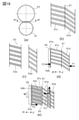
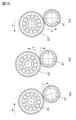
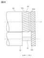
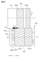
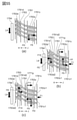
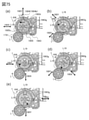
- FIG. 16A is a schematic view of the drive transmission gear 81 and the drive side flange 63 as viewed along their rotation axis directions.
- FIG. 16B is a cross-sectional view of the drive transmission gear 81 at the cutting line AF-AF.
- the shaded portion (hatching) in the figure is a cross section of the mountain portion of the gear, and the portion between the shaded portion and the shaded portion corresponds to the portion where the valley portion of the gear is present.
- FIG. 16C is a cross-sectional view of the drive side flange 63 at the cutting line AF-AF.
- FIG. 16D is a cross-sectional view taken along the cutting line AF-AF of the drive transmission gear 81 before mounting the cartridge.
- FIG. 16E is a cross-sectional view taken along the cutting line AF-AF of the drive transmission gear 81 and the drive side flange 63 after the cartridge B is mounted and before the start of the drive.
- FIG. 17 is a cross-sectional view of the cut surface AF-AF in contact with the meshing pitch circle of the drive transmission gear 81 and the drive side flange 63 immediately after the start of the drive, with FIGS. 17 (a), 17 (b), and 17 (b). c), the state in which time has passed in the order of FIG. 17 (d) is shown.
- 19 (a), 19 (b), and 19 (c) are views of the drive transmission gear 81 and the drive side flange 63 as viewed along the H direction.
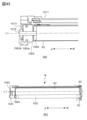
- FIG. 21A is a view of the drive transmission gear 81 and the drive side flange 63 as viewed along the direction perpendicular to the rotation axis direction.
- FIG. 21B is a cross-sectional view taken along the cutting line AD-AD of the first main body gear portion 81c being driven.
- FIG. 21C is a cross-sectional view taken along the cutting line AD-AD of the second main body gear portion 81d being driven.
- the other end 81e of the drive transmission gear 81 is abutted surface of the main frame body 84 due to the urging force F1 of the compression spring 85. It hits 84b and is held.
- the initial position of the drive transmission gear 81 in the rotation axis direction is fixed, and the meshing with the drive side flange 63 is stabilized. be able to.
- the drive side flange 63 meshes with the drive transmission gear 81 as shown in FIG. 19 (a).
- the force required to rotate the drive side flange 63 is larger than the force required to rotate the drive transmission gear 81. Therefore, the drive transmission gear 81 is rotated in the I direction (clockwise direction) by the movement of the drive side flange 63 in the M direction.
- the first main body gear portion 81c or the second main body gear portion 81d of the drive transmission gear 81 is combined with the first gear portion 63c or the second gear portion 63d of the drive side flange 63.
- the drive transmission gear 81 is rotated by a motor (not shown) of the apparatus main body A and rotates in the I direction.
- the drive side flange 63 rotates in the K direction.
- the second main body gear portion 81d of the drive transmission gear 81 first meshes with the second gear portion 63d of the drive side flange 63 to drive the drive transmission gear 81.
- the second main body gear portion 81d generates a thrust force in the H direction of the second gear portion 63d.
- the drive-side flange 63 is restricted from moving in the H direction by the rib 71p, and receives a reaction force in the J direction corresponding to the thrust force in the H direction. Therefore, the second main body gear portion 81d receives a thrust force F5 in the J direction due to the action of the reaction force received from the second gear portion 63d.
- the thrust force F5 causes the drive transmission gear 81 to move in the J direction.
- the first gear portion 63c also meshes with the first main body gear portion 81c, and the first main body gear portion 81c A thrust force F6 is generated in.
- the thrust force F6 is the same thrust force in the J direction as the thrust force F7 that the second main body gear portion 81d has previously received by meshing with the second gear portion 63d.
- the drive transmission gear 81 further moves in the J direction.
- the second main body gear portion 81d When the drive transmission gear 81 further rotates and moves in the J direction, the second main body gear portion 81d does not mesh with the second gear portion 63d as shown in FIG. 17 (c). On the other hand, the meshing between the first gear portion 81c and the first gear portion 63c is maintained, and a thrust force F8 acts on the first gear portion 81c in the J direction. At this time, the drive transmission gear 81 rotates the drive side flange 63 only by the engagement between the first main body gear portion 81c and the first gear portion 63c. That is, the tooth surface 81c1 on the downstream side in the I direction of the first main body gear portion 81c and the tooth surface 63c1 on the upstream side in the I direction of the first gear portion 63c are in contact with each other.
- the amount of movement of the first main body gear portion 81c and the second main body gear portion 81d in the rotation direction due to this movement can be expressed by LL / tan ⁇ 1 and LL / tan ⁇ 2, respectively.
- the movement amount LL / tan ⁇ 2 in the rotation direction of the second main body gear portion 81d is larger than the movement amount LL / tan ⁇ 1 in the rotation direction of the first main body gear portion 81c (LL /. tan ⁇ 1 ⁇ LL / tan ⁇ 2).
- the movement amount in the rotation direction corresponding to the movement amount LL in the J direction is larger in the second main body gear portion 81d than in the first main body gear portion 81c. Therefore, even if the first main body gear portion 81c and the first gear portion 63c are engaged with each other, the second main body gear portion 81d is separated from the second gear portion 63d.
- the first main body gear portion 81c of the drive transmission gear 81 presses the tooth surface (contact portion) 63c1 on the tooth surface 81c1 to rotate the drive side flange 63, and the second main body gear of the drive transmission gear 81.
- the tooth surface 81d2 of the portion 81d comes into contact with the tooth surface 63d2, it is sandwiched by the drive side flange 63.
- the movement of the drive transmission gear 81 in the direction of the rotation axis L1 stops.
- the position in the direction of the rotation axis L1 at this time is set as the equilibrium position. A state in which the drive transmission gear 81 rotates at the balanced position and is driven and transmitted to the drive side flange 63 will be described.
- the force F9 is the thrust force in the J direction that the first main body gear portion 81c receives by the meshing force with the first gear portion 63c
- the force F1 is the H that the second main body gear portion 81d receives by the meshing force with the second gear portion 63d.
- the thrust force in the direction, the force F1 is the urging force of the compression spring 85.
- the drive side flange 63 receives a force from the drive transmission gear 81 and is positioned with respect to the direction of the rotation axis L1 by the side wall 71m or the rib 71p, and a reaction force F11 is generated which balances with the force received from the drive transmission gear 81.
- FIG. 17D shows a case where the drive transmission gear 81 is positioned in contact with the side wall 71 m.
- the force F9, the force F10, the force F1, and the force F11 are balanced, and the drive transmission gear 81 and the drive side flange 63 are positioned in the direction of the rotation axis L1, respectively. It has become.
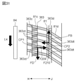
- the drive side flange 63 is sandwiched (contacted) between the first main body gear portion 81c and the second main body gear portion 81d of the drive transmission gear 81 and exerts the following force also in the K direction (rotational direction). It is in the received state. That is, the tooth surface (contact portion) 63c1 of the first gear portion 63c comes into contact with the first main body gear portion 81c arranged on the upstream side in the K direction (first circumferential direction), whereby the drive side flange 63 is K. It receives the driving force FD as the force of the component in the direction of rotation in the direction (predetermined direction).
- the tooth surface (contact portion) 63d2 of the second gear portion 63d comes into contact with the second main body gear portion 81d arranged on the downstream side in the K direction (first circumferential direction), thereby causing K of the drive side flange 63. It receives the regulatory force (braking force) FB as the force of the component in the direction that suppresses (regulates) the rotation in the direction. Therefore, it can be said that the first gear portion 63c is a driving force receiving portion that receives the driving force FD, and the second gear portion 63d is a regulating force receiving portion that receives the regulating force FB.
- the driving force FD is larger than the regulatory force FB.
- the configuration is such that the second gear portion 63d cannot rotate relative to the first gear portion 63c in the opposite direction in the K direction. .. Strictly speaking, since the drive side flange 63 is made of resin and deformation of teeth and members occurs, the second gear portion 63d subjected to the regulatory force FB is in the K direction relative to the first gear portion 63c. After a slight rotation in the opposite (reverse) direction of, the rotation stops and is fixed. Therefore, the regulatory force FB received by the second gear portion 63d acts on (transmits) to the first gear portion 63c. By the same principle, the driving force FD received by the first gear portion 63d acts on (transmits) to the second gear portion 63d.
- the state in which the first gear portion 63c receives the driving force FD and the second gear portion 63d receives the regulating force FB is in the rotation direction (I direction) between the drive side flange 63 and the drive transmission gear 81.
- backlash backlash
- the drive side flange 63 is rotationally driven in the K direction while maintaining the backlashless state. While the drive is transmitted by engaging with each other in the backlashless state, the drive transmission with good rotation accuracy is possible.
- the width (tooth width) W63c of the first oblique tooth (first protrusion) 63ct in the direction of the rotation axis L1 is the width (tooth width) W63d of the second oblique tooth (second protrusion) 63dt in the direction of the rotation axis L1.
- the second gear portion 63d has a second oblique tooth (second protrusion) that is narrower than the first oblique tooth 63ct, which has the widest width (tooth width) in the direction of the most rotating axis L1 of the first gear portion 63c. ) Has 63 dt.
- 46 (a) and 46 (b) are cross-sectional views of the cut surface AF-AF in contact with the meshing pitch circle of the drive transmission gear 81 and the drive side flange 63 of the second gear portion 63d and the second main body gear portion 81d. Is.
- the helix angle ⁇ 1 As described above, when the first gear portion 63c is the gear portion that receives the driving force FD and the second gear portion 63d is the gear portion that receives the regulation force FB, the helix angle ⁇ 1 and the first of the first gear portion 63c.
- the setting of the helix angle ⁇ 2 of the 2 gear portion will be described.
- the helix angle ⁇ 2 is larger than the helix angle ⁇ 1 ( ⁇ 2). > ⁇ 1).
- the thrust force applied by the first gear portion 63c to the first main body gear portion 81c and the thrust force applied by the second gear portion 63d to the second main body gear portion 81d do not balance, and the direction of the rotation axis L1 of the drive transmission gear 81.
- the position of is not determined by the equilibrium position.
- the helix angle ⁇ 1 of the first gear portion 63c of the drive side flange 63 is preferably 10 ° or more ( ⁇ 1 ⁇ 10 °), more preferably 15 ° or more ( ⁇ 1 ⁇ 15 °), and 20 ° or more ( ⁇ 1 ⁇ 20 °). Is more preferable. The reason is that, in general, if the tooth width (the width of the gear tooth in the direction of the rotation axis L1) is the same, the larger the helix angle, the larger the meshing ratio and the higher the rotation accuracy.
- the helix angle ⁇ 1 is preferably 40 ° or less ( ⁇ 1 ⁇ 40 °), more preferably 35 ° or less ( ⁇ 1 ⁇ 35 °). The reason is that, in general, when the helix angle is large, the moldability by the mold deteriorates.
- the helix angle ⁇ 2 of the second gear portion 63d of the drum gear 63 is preferably 40 ° or less ( ⁇ 2 ⁇ 40 °), more preferably 35 ° or less ( ⁇ 2 ⁇ 35 °). The reason is that, in general, when the helix angle is large, the moldability by the mold deteriorates. Further, the helix angle ⁇ 2 of the second gear portion 63d of the drum gear is preferably 20 ° or more ( ⁇ 2 ⁇ 20 °), and more preferably 25 ° or more ( ⁇ 2 ⁇ 25 °). The reason is that, as shown in FIGS.
- the larger the helix angle ⁇ 2 the larger the width E in the rotation direction (K direction) of the contact surface with the second main body gear portion 81d. Is.
- the helix angle ⁇ 2 is set to 35 °.
- the helix angle ⁇ 1 is preferably 10 ° or more and 40 ° or less (15 ° ⁇ ⁇ 1 ⁇ 40 °), more preferably 15 ° or more and 40 ° or less (15 ° ⁇ ⁇ 1 ⁇ 40 °), and 20 ° or more. It is more preferably 35 ° or less (20 ° ⁇ ⁇ 1 ⁇ 35 °).
- the helix angle ⁇ 2 is preferably 20 ° or more and 40 ° or less (20 ° ⁇ ⁇ 2 ⁇ 40 °), and more preferably 25 ° or more and 35 ° or less (25 ° ⁇ ⁇ 2 ⁇ 35 °).
- the helix angle ⁇ 1 is set to 20 ° and the helix angle ⁇ 2 is set to 35 °, satisfying the above conditions. ⁇ Width of cylindrical portion 63e>
- FIG. 47A is a schematic view of the drive side flange 63 and the drive transmission gear 81 when the cartridge B is mounted, as viewed from a direction orthogonal to the rotation axis L1.
- FIG. 47B is a schematic view of the driving side flange 63 and the driving transmission gear 81 being driven as viewed from a direction orthogonal to the rotation axis L1.
- the first gear portion 63c comes into contact with the second main body gear portion 81d with respect to the direction of the rotation axis L1, and the second gear portion 63d is the first main body gear portion. It is possible to prevent contact with 81c. Further, by providing the cylindrical portion 63e, when the drive transmission gear 81 is driven and the drive transmission gear 81 moves to the equilibrium position, the first main body gear portion 81c comes into contact with the second gear portion 63d, and , It is possible to prevent the second main body gear portion 81d from coming into contact with the first gear portion 63c.
- the width (length) of the cylindrical portion 63e in the direction of the rotation axis L1 is synonymous with the width (length) of the gap g in the direction of the rotation axis L1.
- the above-mentioned contact may occur in the following two situations. First, as shown in FIG. 47 (a), when the cartridge B is mounted on the apparatus main body A, the other end 81e of the drive transmission gear 81 is held against the abutting surface 84b of the main frame body 84. The situation. The second is a situation in which the drive transmission gear 81 is driven and moves toward the balanced position, as shown in FIG. 47 (b).
- the positions of the first gear portion 63c and the second gear portion 63d of the drive side flange 63, the positions of the first main body gear portion 81c and the second main body gear portion 81d of the drive transmission gear 81, and the equilibrium position are the elements shown below. Can fluctuate under the influence of. Specifically, (1) the tolerance in the direction of the rotation axis L1 of related parts such as the drive side flange 63, the drive transmission gear 81, and the cleaning frame body (drum frame body) 60a, and (2) the rotation axis of the drive side flange 63.
- Tolerance related to the distance between L1 and the rotation axis L2 of the drive transmission gear 81 (3) Tolerance of phase in the rotation direction of the teeth of the first gear portion 63c and the second gear portion 63d of the drive side flange 63, (4).
- the difference in the rotational phase of the teeth between the first main body gear portion 81c and the second main body gear portion 81d of the drive transmission gear 81 (5) deformation of the teeth due to the maximum drive load, the drive side flange 63 and the drive transmission gear 81. Thermal expansion and contraction.
- the width (length) We of the cylindrical portion 63e (or the gap g) in the direction of the rotation axis L1 is set.
- the width We is set so that the width (tooth width, length) in the direction of the rotation axis L1 of the teeth of the first gear portion 63c is Wc, and when this is used as a reference, the following equation B1 is satisfied. It is preferable to do so.
- the width We is set to Wd as the width (tooth width, length) in the direction of the rotation axis L1 of the teeth of the second gear portion 63c. It is preferable to set so as to satisfy the following formula B3.
- Wd ⁇ ⁇ ⁇ (Equation B3) ⁇ Rotation accuracy>
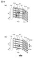
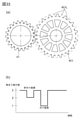
- FIG. 22A is a view of the drive transmission gear 81 and the drive side flange 63 as viewed along the direction perpendicular to the rotation axis direction.
- FIG. 22B is a partial cross-sectional view of the meshing portion of the general oblique tooth gears 51 and 53 as a comparative example.
- FIG. 22 (c) is a partial cross-sectional view of the cut surface AD-AD in contact with the meshing pitch circle of the drive transmission gear 81 and the drive side flange 63.
- FIG. 22D is a partial perspective view of the oblique tooth gear 51.
- FIG. 22 (e) is a partial perspective view of the drive transmission gear 81.
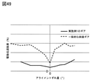
- FIG. 49 is a graph comparing the drive transmission error when the alignment of the drive side flange 63 and the oblique tooth gear 53 is misaligned.
- the tooth surfaces of the oblique tooth gears on the drive side and the driven side may mesh with each other without being parallel in the tooth streak direction due to molding accuracy, play and deformation of the shaft portion. be.
- Such a state is generally called a misaligned state.
- the alignment of the oblique tooth gear (drive side) 51 and the oblique tooth gear (driven side) 53, which are general oblique tooth gears, is deviated by ⁇ °, the oblique tooth gears 51 and 53 are at one end of the tooth surface in the axial direction.
- the meshing rate is significantly reduced as compared with the state where the meshing is performed only at the position and the alignment is not deviated.
- FIG. 22D shows a region in which the tooth surface of the oblique tooth gear 51 meshes with the oblique tooth gear 53 when the alignment is deviated, and the width of this region is defined as the width LP.
- the drive side flange 63 is the first gear portion 63c of the drive side flange 63, the second gear portion 63d, and the first main body gear portion 81c of the drive transmission gear 81.
- the main body gear portion 81d is sandwiched and rotated.
- a pinching force FC that is, a rotary drive brake acting on the second main body gear portion 81d is generated.
- the reaction of the pinching force FC is added to the force applied to the tooth surface of the first main body gear portion 81c that presses the first gear portion 63c in the I direction, and becomes a force FB.
- FIG. 22E shows a region that meshes with the first gear portion 63 of the drive side flange 63 of the tooth surface of the first main body gear portion 81c of the drive transmission gear 81 when the alignment is deviated, and the width of this region is shown. Is the width LQ. Since the force FB is larger than the force FA, when the width LP in FIG. 22 (d) and the width LQ in FIG.
- the width LQ is larger than the width LP. Therefore, when the alignment is misaligned, the decrease in the overlapping meshing ratio of the first main body gear portion 81c and the first gear portion 63c is smaller than that of the oblique tooth gears 51 and 53.
- FIG. 49 shows the driven side oblique tooth gear 53 and the drive with respect to the amount of misalignment when the general oblique tooth gears 51 and 53 are used and when the drive transmission gear 81 and the drive side flange 63 of this embodiment are used. It is a graph which showed the measurement result of the drive transmission error of a side flange 63.
- the gear specifications such as the number of teeth and the backlash amount in the inter-axis direction of 0.15 mm and the load torque are 0.
- the conditions such as 25 Nm and rotation speed 270 rpm were the same, and the shaft and gear were fitted without backlash.
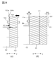
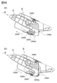
- FIG. 24A is a schematic diagram of a drive transmission configuration using a conventional oblique tooth gear.
- FIG. 24B is a schematic diagram of the drive transmission configuration of this embodiment.
- the oblique tooth gear 101 receives a thrust force (force in the axial direction) FD due to the meshing force.
- the oblique tooth gear 101 moves in the H direction toward the non-driving side, and the end surface 101a of the oblique tooth gear 101 and the abutting surface 184b of the main frame body 84 abut and slide, and these are worn. ..
- the position in the direction of the rotation axis L1 is determined by the drive side flange 63 and the spring 85 (not shown) during driving.
- the end surface 81e in the H direction and the end surface 81f in the J direction of the drive transmission gear 81 do not slide because a gap AA is formed between the main frame body 84 and the second drive side plate 83. Therefore, wear of the two end faces 81e and 81f of the drive transmission gear 81, the main frame body 84, and the second drive side plate 83 can be suppressed, and the durability can be improved. ⁇ Comparison with conventional coupling drive>
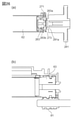
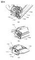
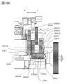
- FIG. 26A is a cross-sectional view of a drive transmission unit of a conventional coupling drive, and the cross section thereof includes a rotation axis of the coupling.
- FIG. 26B is a cross-sectional view of the drive transmission unit of the present embodiment, and the cross section thereof includes the rotation axis (L1) of the drive side flange 63 and the rotation axis of the drive transmission gear 81.
- FIG. 27 is a graph showing the amount of deformation between the coupling drive and the drive transmission gear.
- a drive side flange 263 provided with a convex coupling 263a having a twisted polygonal prism shape is attached to the end of the drum 62 of the cartridge. ..
- the drum flange 263 has a support portion 263b which is a cylindrical portion having a diameter smaller than the diameter of the drum 62.
- the device body has a drive transmission gear 281 with a concave coupling 281a into which the coupling 263a is inserted and engaged.
- the coupling 263a is provided at the end of the drive side flange 263 in the direction of the rotation axis. Therefore, the twist amount of the drive side flange 263 during driving in the coupling drive is larger than the twist amount of the drive side flange 63 in the gear drive of the present embodiment shown in FIG. 26 (b).
- FIG. 27 shows that the gear drive (drive with the drive side flange 63) is the coupling drive (drum flange) as shown in the simulation result of the deformation amount of the drive member (drum flange 263, drive side flange 63) in the rotation direction. The amount of deformation is smaller than that of driving at 263).
- the amount of deformation of the drive member in the rotation direction will be described.
- This amount of deformation fixes the drum 62 side of the drum coupling 263 and the drive side flange 63, and has the same static load torque of 0.25 N in the engaging portion with the drive input member 281 or the meshing portion with the drive transmission gear 81. It is the amount of displacement of the drive transmission point to the drum 62 in the rotation direction when m is applied.
- the drive transmission point is a point fixed to the drum 62. Then, the displacement amount is converted into the displacement amount when there is no twist at a predetermined point on the surface of the drum 62.
- the change in the amount of deformation of the drive member when the load torque of the cartridge B fluctuates is smaller in the gear drive than in the coupling drive, and the drum due to the change in the amount of deformation.
- the fluctuation of the rotation speed of 62 becomes small. That is, the density unevenness of the image in the rotation direction of the drum 62 on the image when the load torque fluctuation of the cartridge B occurs (the sub-scanning direction between the scanning lines formed when scanning the surface of the drum 62 with the laser beam L). It is possible to keep the pitch variation (caused by pitch unevenness)) low.
- the deterioration of the rotational accuracy of the drum 62 with respect to the load torque fluctuation can be suppressed as compared with the conventional coupling drive configuration. Can be done.
- FIG. 28A is a cross-sectional view of the drum 62 of the retracting mechanism in cross section including the rotation axis.
- FIG. 28B is a schematic cross-sectional view of an image forming apparatus provided with a retracting mechanism.
- 28 (c) and 28 (d) are cross-sectional views of the drive transmission gear 281 and the retracting mechanism, and the cross section thereof includes the rotation axis of the drive transmission gear 281.
- the main body of the coupling-driven image forming apparatus is provided with a retracting mechanism including a link 210, a cylindrical cam 212, and a compression spring 214.
- One end of the link 210 is connected to the opening / closing door 211 of the apparatus main body A.
- the other end of the link 210 is coaxial with the drive input member 281 and is connected to a cylindrical cam 212 rotatably provided between the drive input member 281 and the side wall 213.
- the cylindrical cam 212 has a slope 212d, a convex surface 212c, and a concave surface 212e having a height difference in the rotation direction on one end surface in the axial direction.
- the side wall 213 has a slope 213e, a convex surface 213f, and a concave surface 213g at locations facing each of the slope 212d, the convex surface 212c, and the concave surface 212e. Further, as shown in FIG. 28 (d), the drive transmission gear 281 is urged in the H direction by the compression spring 214.
- the cylindrical cam 212 is rotated in the I direction via the link 210, and the cylindrical cam 212 and the convex surfaces 212c and 213f provided on the side wall 213 come into contact with each other. Then, the cylindrical cam 212 is moved in the J direction.
- the cylindrical cam 212 moves the drive input member 281 in the J direction against the urging force of the compression spring 214. As a result, the drive input member 281 moves away from the drum flange 263 (see FIG. 26A) and disengages the coupling 281a from the coupling 263a (see FIG. 26A). As a result, the cartridge B can be removed.
- the cylindrical cam 212 is in contact with the cylindrical cam 212 and the slopes 212d and 213e provided on the side wall 213 via the link 210, and I Rotate in the opposite direction.
- the cylindrical cam 212, the side wall 213, and the drive input member 281 do not come into contact with each other in the rotation axis direction, and as shown in FIG. 28 (d), the drive input member 281 is moved in the H direction by the urging force of the compression spring 214. It becomes possible to move toward.
- the drive input member 281 moves in a direction approaching the drum flange 263 (see FIG. 26A), and the coupling 281a and the coupling 263a (see FIG. 26A) can be engaged with each other.
- first main body gear portion 81c and the second main body gear portion 81d of the drive transmission gear 81 have the same number of teeth, but the number of teeth does not necessarily have to be the same.
- the reduction ratio with the unit 63d needs to be the same.
- the second main body gear portion 81d of the drive transmission gear If the number of teeth is 40 and the number of teeth of the second gear portion 63d of the drive side flange 63 is 60, the reduction ratio is the same 2: 3.
- the gear of the drive transmission gear 81 can be sandwiched by the first gear portion 63c and the second gear portion 63d of the drive side flange 63, it is possible to make the backlashless state with respect to the rotation direction. Is. ⁇ Modification 2>
- first gear portion 181c and the second gear portion 181d of the drive transmission gear 181 have different numbers of teeth, and the number of teeth on one side is not an integral multiple of the number of teeth on the other side.
- the first gear portion 163c and the second gear portion 163d of the drive side flange 163 also have different numbers of teeth, and the number of teeth on one side is not an integral multiple of the number of teeth on the other side.
- FIG. 25A is a schematic diagram of a drive transmission configuration using the drive transmission gear 81 of the present embodiment described above.
- 25B is an explanatory diagram of a drive transmission unit using the drive transmission gear 181 and the drive side flange 163 of the modified example.
- 25 (c) and 25 (d) show a state in which the drive transmission gear 181 is in a balanced position after the drive transmission gear 181 is driven.
- FIG. 25C shows a tooth crest of the first gear portion 181c of the drive transmission gear 181 and a tooth crest of the second gear portion 181d in the meshing portion between the drive side flange 163 and the drive transmission gear 181. This is a state in which the tooth ridges of the first gear portion 163c of the drive side flange 163 and the tooth ridges of the second gear portion 163d are in phase with each other.
- FIG. 25C shows a tooth crest of the first gear portion 181c of the drive transmission gear 181 and a tooth crest of the second gear portion 181d in the meshing portion between the drive side flange 163 and the drive transmission gear 181.
- the phase of the tooth ridges and ridges of the first gear portion 181c and the second gear portion 181d is the rotation of the gear. It depends on the phase of the direction. For example, if there is a position Q1 in which the phase of the ridge portion 181cs of the tooth of the first gear portion and the ridge portion 181ds of the second gear portion match depending on the phase in the rotation direction of the gear, the ridge portion 181cs of the first gear portion and the first There is also a position Q2 that is in phase with the valley portion 181db of the two gear portion.
- FIGS. 25 (c) and 25 (d) show the drive with respect to the drive side flange 163 by the initial (before drive) meshing phase between the drive transmission gear 181 and the drive side flange 163 in the rotation direction.
- the equilibrium position of the transmission gear 181 in the axial direction is different.
- FIG. 25 (c) shows the case where the balance position of the drive transmission gear 181 is the most downstream side in the H direction
- FIG. 25 (d) shows the case where the balance position of the drive transmission gear 181 is the most downstream side in the J direction. There is.
- the amount of change in the equilibrium position is, for example, the first gear portion 181c and the second gear portion 181d of the drive transmission gear 181 with reference to the intermediate line between the first gear portion 163c and the second gear portion 163d of the drive side flange 163. It can be expressed by the amount of deviation of the boundary line with. That is, in the state of FIG. 25 (c), the deviation amount LD in the J direction and in the state of FIG. 25 (d), the deviation amount LE in the H direction, so that the sum (LD + LE) of the deviation amount LD and the deviation amount LE is. , The amount of change in the equilibrium position in this modification.
- the distance LF width of the cylindrical portion 163e
- the drive transmission between the first gear portion 163c and the second gear portion 163d of the drive side flange 163 are taken into consideration in consideration of the amount of change in the equilibrium position (LD + LE).
- the gap LG between the gear 181 and the main body frame 184 is set.
- the number of teeth of the first main body gear portion 81c and the second main body gear portion 81d is the same, and the first main body gear portion 81c and the second main body gear portion 81c have the same number of teeth.
- the positional relationship between the mountain portion 81cs and the mountain portion 81ds with the main body gear portion 81d does not change with the phase in the rotation direction. Therefore, the equilibrium position where the drive transmission gear 81 is positioned in the axial direction with respect to the drive side flange 63 does not change. That is, it is not necessary to consider the amount of change in the equilibrium position (LD + LE), which had to be considered in the modified example.
- the gap (width of the cylindrical portion 63e) between the first gear portion 63c and the second gear portion 63d of the drive side flange 63 can be designed to be smaller than that of the modified example, and the cartridge B can be designed. It can be miniaturized. Further, the apparatus main body A of the present embodiment can be designed so that the gap between the drive transmission gear 81 and the main body frame 84 is smaller than that of the modified example. As a result, the cartridge B and / or the apparatus main body A can be miniaturized. ⁇ Other variants>
- the cartridge B has described the cartridge B in which the toner remaining on the drum 62 without being transferred is scraped off by bringing the rubber blade 77a into contact with the drum 62 and stored in the waste toner chamber 71b (FIG. FIG. 3).
- the cartridge B may have a cleanerless configuration.
- the drive transmission configuration of the drive side flange 63 and the drive transmission gear 81 of the above-described embodiment may be applied to the cartridge having the cleanerless configuration.
- FIG. 23 is a cross-sectional view of the cartridge B having a cleanerless configuration.
- the cartridge B having a cleanerless configuration is configured and controlled so that the residual toner on the drum 62 can be recovered by the developing roller 32. Therefore, the cartridge B does not have a rubber blade in contact with the drum 62. Therefore, the cartridge B having a cleanerless configuration drives the drum 62 by the amount that the rubber blade 77a, which has become a resistance when rotating the drum 62, is absent, as compared with the configuration in which the rubber blade 77a is in contact with the drum 62.
- the required torque is small. As a result, the rotation speed of the drum 62 tends to fluctuate due to the influence of the impact when the sheet material PA is conveyed.
- the rotation accuracy of the drum 62 may decrease.
- the drum 62 can be driven between the drive side flange 63 and the drive transmission gear 81 in a backlashless state. For this reason, the rotation of the drum 62 due to the absence of the rubber blade is compared with the configuration in which backlash and backlash in the rotation direction exist between the drive side flange and the drive member on the main body side to drive and transmit the drive. It is possible to suppress a decrease in accuracy.
- FIG. 29 is a schematic view showing the engagement between the drive side flange 63 and the developing roller gear 30.
- the developing roller gear 130 fixed to the end of the developing roller shaft 31 meshes with the second gear portion 63d. Since the second gear portion 63d has a larger helix angle than the first gear portion 63c, the meshing ratio also increases accordingly.
- the developing roller gear 130 that meshes with the second gear portion 63d can have a smaller tooth width than the developing roller gear 30 that meshes with the first gear portion 63d.
- FIG. 30 is a perspective view of the cartridge B.
- the developing roller gear 230 is provided with a first developing gear portion 230c and a second developing gear portion 230d that mesh with the first gear portion 63c and the second gear portion 63d of the drive side flange 63, respectively.
- the developing roller gear 230 moves on the rotation axis L1 by the same principle that the drive transmission gear 81 moves in the direction of the rotation axis L1 and reaches the equilibrium position in the above-described embodiment. Move in the direction and reach the equilibrium position.
- the developing roller gear 230 is in the balanced position, the developing roller gear 230 is driven in a backlashless state with respect to the drive side flange 63, so that deterioration of the rotational accuracy of the developing roller 32 when the alignment is misaligned or the load fluctuates is suppressed. can do. ⁇ Application to the configuration that drives the developing roller gear without going through the drive side flange>
- FIG. 44 is a partial perspective view of the cartridge B showing the drive train to the developing roller 532. For the sake of explanation, a part of the frame of the cartridge B is not described.
- the developing roller 532 is not configured to transmit the driving force from the driving side flange 63, but is configured to transmit the driving force via another path.
- the cartridge B has a developing coupling member 89 that can be engaged with a coupling member (not shown) for driving the developing roller of the apparatus main body A.
- the cartridge B is provided with idler gears 90 and 91 that mesh with the gear portion 89a of the developing coupling member 89, and has a developing roller gear 530 that meshes with the idler gear 91 at one end of the shaft of the developing roller 532.
- the developing roller 530 is driven by transmitting the driving force received by the developing coupling member 89 via the idler gears 90 and 91 and the developing roller gear 530. Therefore, for example, the development coupling member 89 can be driven while the drive side flange 63 is stopped, and the drive of the development coupling member 89 can be controlled separately from the drive of the drive side flange 63.
- the drive side flange 63 was attached to the end of the drum 62, but the developing roller gear 30 is provided with the first gear portion 63c, the second gear portion 63d, and the cylindrical portion 63e, and the drive transmission gear 81 provides the developing roller 30. It can also be applied to driving configurations.
- the object to be driven by the drive transmission gear 81 is not limited to a developer carrier such as a drum 62 and a developing roller 30 that carries a toner (developer).
- the target to be driven by the drive transmission gear 81 may be, for example, a transport member (or agitator member) 43 for transporting (or stirring) toner, a charging roller 66, or a supply member for supplying toner to the developing roller 30. ..
- the cartridge B may be a cartridge having no photoconductor such as the drum 62.
- Example 2 will be described below with reference to FIG. 31.
- the configurations of the first gear portion and the second gear portion provided on the drive side flange are different from those in the first embodiment. Since the other points are the same as those in the first embodiment, the description thereof will be omitted.
- FIG. 31 is a cross-sectional view of the meshing portion between the drive transmission gear 81 and the drive side flange 263, and the cross section is a surface in contact with these meshing pitch circles.
- the drive side flange 263 has a first gear portion (first unit side gear portion) 263c and a second gear portion (second unit side gear portion) 263d.
- the first gear portion 263c includes a plurality of first flat teeth (first protrusions) 263ct having a tooth width that can be inserted between the teeth of the first main body gear portion 81c.
- the second gear portion 263d includes a plurality of second flat teeth (second protrusions) 263dt having a tooth width that can be inserted between the teeth of the second main body gear portion 81d.
- the width (tooth width) of the first flat tooth 263 ct in the direction of the rotation axis L1 is larger than the width (tooth width) of the second flat tooth 263 dt in the direction of the rotation axis L1.
- the plurality of first flat teeth and the plurality of second flat teeth are protrusions protruding in the radial direction about the rotation axis L1 and are arranged at positions displaced in the circumferential direction about the rotation axis L1.
- the drive transmission gear 81 rotates in the I direction, so that the drive transmission gear 81 moves to the equilibrium position and becomes a backlashless state as in the first embodiment. That is, the first main body gear portion 81c meshes with the first gear portion 263c and receives the reaction force of the driving force FD and the thrust force F209 in the J direction from the contact point (contact portion) CP1 of the first gear portion 263c.
- the second main body gear portion 81d meshes with the second gear portion 263d and receives the reaction force of the regulatory force FB and the thrust force F210 in the H direction from the contact point (contact portion) CP2 of the second gear portion 263d.
- Example 3 will be described below with reference to FIG. 32.
- the configurations of the first gear portion and the second gear portion provided on the drive side flange are different from those in the first embodiment. Since the other points are the same as those in the first embodiment, the description thereof will be omitted.
- FIG. 32 is a diagram showing a drive side flange 363.
- the drive side flange 363 has a first gear portion 363c and a second gear 363d1.
- the first gear portion (first unit side gear portion) 363c includes a plurality of first oblique tooth gears (first protrusions) 363ct provided by being divided into a plurality of parts in the direction of the rotation axis L1.
- the plurality of first oblique tooth gears (projections) 363ct are divided in the direction of the rotation axis L1, one oblique tooth substantially extending in the direction of the rotation axis L1 with respect to the first main body gear portion 81c. Functions as a tooth.
- the tooth surface of the plurality of first oblique tooth gears (projections) 363ct is a plurality of force receiving portions that receive force from the first main body gear portion 81c. Therefore, it can be said that the plurality of force receiving portions that receive the force from the first main body gear portion 81c are provided over the plurality of first oblique tooth gears (first protrusions) 363 ct.
- the tooth surface of the plurality of first oblique tooth gears (projections) 363ct constitutes an oblique tooth surface divided into a plurality in the direction of the rotation axis L1, or is centered on the rotation axis L1 of the drive side flange 363.
- the plurality of oblique tooth-shaped protrusions 363ct constitute one tooth of the first main body gear portion 81c and one tooth of the corresponding oblique tooth gear.
- the tooth surface of the plurality of second oblique tooth gears (projections) 363 dt is a plurality of force receiving portions that receive force from the second main body gear portion 81d. Therefore, it can be said that the plurality of force receiving portions that receive the force from the second main body gear portion 81d are provided over the plurality of second oblique tooth gears (second protrusions) 363 dt.
- the second gear portion (second unit side gear portion) 363d includes a plurality of second oblique tooth gears (projections) 363 dt provided by being divided into a plurality of parts in the direction of the rotation axis L1.
- the second main body gear portion 81d is substantially extended in the direction of the rotation axis L1. Functions as one oblique tooth.
- the tooth surface of the plurality of second oblique tooth gears (projections) 363dt constitutes an oblique tooth surface divided into a plurality of parts in the direction of the rotation axis L1, or is centered on the rotation axis L1 of the drive side flange 363. It can be said that the oblique tooth surface is divided into a plurality of parts in the circumferential direction.
- the plurality of oblique tooth-shaped protrusions 363dt constitute one tooth of the second main body gear portion 81d and one tooth of the corresponding oblique tooth gear.
- Example 4 will be described below with reference to FIG. 33.
- the configurations of the first gear portion and the second gear portion provided on the drive side flange are different from those in the first embodiment. Since the other points are the same as those in the first embodiment, the description thereof will be omitted.
- the drive side flange 463 has two gear portions (first unit side gear portion and second unit side gear portion) like the first gear portion 63c and the second gear portion 63d of the drive side flange 63 of the first embodiment. ing. At least one of the two gear portions has a missing tooth portion (apparently, a portion where the teeth of the gear are thinned out) 463L.
- FIG. 33A is a view of the drive side flange 463 and the drive transmission gear 81 meshing with each other in a cross section orthogonal to the rotation axis L1.
- FIG. 33B is a graph showing the transition of the number of teeth of the meshing gear.
- each gear part of the drive side flange 463 and each gear part of the drive transmission gear 81 is N teeth when rounded down to the nearest whole number
- each gear part of the drive side flange 463 is missing every N-1 tooth at the maximum. It may have a tooth portion 463L.
- the meshing ratio is 1 or more.
- Example 5 will be described below with reference to FIG. 34.
- the configurations of the first gear portion and the second gear portion provided on the drive side flange are different from those in the first embodiment. Since the other points are the same as those in the first embodiment, the description thereof will be omitted.
- the drive side flange 563 has two gear portions (first unit side gear portion and second unit side gear portion) like the first gear portion 63c and the second gear portion 63d of the drive side flange 63 of the first embodiment. ing. At least one of the two gear portions has a missing tooth portion 563L.
- FIG. 34A is a view of the drive side flange 563 and the drive transmission gear 81 meshing with each other in a cross section orthogonal to the rotation axis L1.
- FIG. 34 (b) is a diagram showing changes in the number of teeth of the meshing gears. As shown in FIG.
- the teeth of the drive-side flange 563 are not arranged at equal pitches in the circumferential direction. That is, it can be said that the size of the plurality of missing tooth portions 563 in the circumferential direction is not constant, or the apparent thinning amount of all the missing tooth portions 563 is not the same. In other words, it suffices if they are arranged in the rotation direction at intervals LI, LJ that are twice the natural number (1, 2, ...) Of the minimum pitch LH between adjacent teeth. Even if such a missing tooth portion 563 is provided, it is sufficient that there are at least one meshing tooth (the meshing ratio is 1 or more).
- Example 6 will be described below with reference to FIG. 35.
- the configurations of the first gear portion and the second gear portion provided on the drive side flange are different from those in the first embodiment.
- the first gear portion 63c and the second gear portion 63d of the first embodiment each have an involute tooth profile oblique tooth, but in this embodiment, the difference is that the diagonal tooth is not an involute tooth profile. Since the other points are the same as those in the first embodiment, the description thereof will be omitted.
- FIG. 35 is a perspective view of the drive side flange 763.
- the drive side flange 763 has a first gear portion (first unit side gear portion) 763c and a second gear portion (second unit side gear portion) 763d.
- the first gear portion 763c includes a plurality of first protrusions 763ct
- the second gear portion 63d includes a plurality of second protrusions 763dt.
- the first protrusion 763ct and the second protrusion 763dt are protrusions protruding in the radial direction about the rotation axis L1, and the cross-sectional shape in the cross section orthogonal to the rotation axis L1 is a trapezoid whose width narrows toward the tip. ..
- first protrusion 763ct and the second protrusion 763dt are oblique teeth that are twisted and arranged with respect to the rotation axis L1. Even in such a configuration, the first gear portion 763c and the second gear portion 763d function as oblique tooth gears in meshing with the drive transmission gear 81. Therefore, when the drive transmission gear 81 rotates in the I direction, the drive transmission gear 81 moves to the equilibrium position and becomes a backlashless state as in the first embodiment.
- the cross-sectional shape of the first protrusion 763ct and the second protrusion 763dt is not limited to a trapezoid, but may be a chevron shape composed of a rectangle, a triangle, or a curve, or a shape with chamfered corners.
- Example 7 will be described below with reference to FIG. 36.
- the configurations of the first gear portion and the second gear portion provided on the drive side flange are different from those in the first embodiment.
- the twisting direction was reversed as compared with the first gear portion 63c and the second gear portion 63d of the first embodiment.
- the twisting directions of the first main body gear portion and the second main body gear portion of the drive transmission gear are also reversed as compared with the first embodiment. Since the other points are the same as those in the first embodiment, the description thereof will be omitted.
- FIG. 36 is a schematic view showing the engagement between the drive transmission gear 881 and the drive side flange 863.
- the twisting direction of the first gear portion (first unit side gear portion) 863c and the second gear portion (second unit side gear portion) 863d of the drive side flange 863 is the tooth surface toward the J direction. Is a twisting direction so as to shift toward the I direction.
- the twisting direction of the first gear portion 881c and the second gear portion 881d of the drive transmission gear 881 is a direction in which the tooth surface is twisted so as to be displaced toward the K direction toward the J direction.
- the direction of the thrust force F21 due to the meshing applied to the drive transmission gear 881 while driving the drive transmission gear 881 is also opposite to that of the first embodiment. Therefore, when moving to the equilibrium position in the axial direction, a space having a width LK for the drive transmission gear 881 to move in the H direction is required. Therefore, a compression spring 185 for urging the drive transmission gear 881 in the J direction is provided, and the drive transmission gear 881 is placed against the positioning portion 83b of the second drive side plate 83 before mounting the cartridge B. ing.
- Example 8 will be described with reference to FIG. 37.
- This embodiment has a different configuration in which the cartridge B is mounted on the main body of the apparatus as compared with the first embodiment. Since the other points are the same as those in the first embodiment, the description thereof will be omitted.
- FIG. 37 is a perspective view of the image forming apparatus 800.
- the insertion direction for inserting the cartridge B into the apparatus main body A is parallel to or substantially parallel to the rotation axis L1 of the drum 62. Even if the cartridge B is completely inserted in the direction parallel to the rotation axis L1, there is a distance between the drive side flange 63 and the drive transmission gear (not shown) of the apparatus main body A in the direction orthogonal to the rotation axis L1. , Can't mesh.
- the cartridge B is displaced at least in the direction VD orthogonal to the rotation axis L1 by the lift-up mechanism (not shown) provided in the device main body A connected to the door 211, and the drive side flange 63 and the device main body are displaced. It meshes with a drive transmission gear (not shown) of A.
- the drive operation after the drive side flange 63 and the drive transmission gear (not shown) mesh with each other is the same as in the first embodiment, and the drive transmission gear moves to the equilibrium position and becomes a backlashless state as in the first embodiment.
- the cartridge B When the cartridge B is displaced at least in the direction VD orthogonal to the rotation axis L1 by the lift-up mechanism, the cartridge B may be displaced not only in the direction orthogonal to the rotation axis L1 but also in the direction of the rotation axis L1. Further, the lift-up mechanism may be configured to rotate the cartridge B around an axis orthogonal to the rotation axis L1 and displace the drive side flange 63 in the direction VD orthogonal to the rotation axis L1.
- the direction in which the cartridge B is at least orthogonal to the rotation axis L1 in the process of inserting the cartridge B into the device main body A may be displaced to VD.
- the cartridge B in the initial stage of the insertion stroke of the cartridge B into the apparatus main body A, the cartridge B is guided by a guide (not shown) so as to move the cartridge B in a direction parallel to the rotation axis L1.
- the cartridge B is guided by a guide (not shown) so as to displace the cartridge B in a direction VD orthogonal to at least the rotation axis L1.
- the cartridge B may be configured to change its moving direction (mounting direction) during the insertion process.
- Example 9 will be described below with reference to FIG. 38.
- the configurations of the first gear portion and the second gear portion provided on the drive side flange are different from those in the first embodiment.
- the arrangement of the first gear portion 963c and the second gear portion 963d with respect to the direction of the rotation axis L1 is reversed from that of the first gear portion 63c and the second gear portion 63d of the first embodiment.
- the positions of the first main body gear portion and the second main body gear portion of the drive transmission gear with respect to the direction of the rotation axis L1 are also reversed as compared with the first embodiment. Since the other points are the same as those in the first embodiment, the description thereof will be omitted.
- FIG. 38 is a schematic view showing the meshing of the drive transmission gear 981 and the drive side flange 963.
- the drive side flange 963 has a first gear portion (first unit side gear portion) 963c and a second gear portion (second unit side gear portion) 963d.
- the helix angle of the second gear portion 963d is larger than the helix angle of the first gear portion 963c.
- the first gear portion 963c is arranged on the downstream side (drive side) in the J direction from the second gear portion 963d. That is, the second gear portion 963d is arranged between the first gear portion 963c and the drum 62 with respect to the direction of the rotation axis L1.
- the drive transmission gear 981 is provided with a first gear portion 981c that meshes with the first gear portion 963c and a second gear portion 981d that meshes with the second gear portion 963d. Also in these cases, the position with respect to the direction of the rotation axis L1 has the opposite relationship to that of the first embodiment.
- the drive transmission gear 981 moves to a balanced position.
- the first gear portion 963c receives the driving force FD (see FIG. 17 (d)) and the second gear portion 963d receives the regulating force FB (see FIG. 17 (d)) as in the first embodiment. Received and becomes backlashless state.
- the end portion on the drive side (downstream side in the J direction) of the drum unit 969 in which the drive side flange 963 and the drum 62 are integrated is rotatably supported by the shaft member 86 (see also FIG. 4).
- the first gear portion 963c is arranged at a position closer to the root of the shaft member 86 than the second gear portion 963d.
- the force applied to the tooth surface of the first gear portion 963c that receives the drive force FD is larger than that of the second gear portion 963d that receives the regulation force FB.
- the driving force FD may act so as to cause the rotation axis L1 of the drum unit 969 to tilt, and the drum 62 may be tilted with respect to the ideal rotation axis L1.
- the first gear portion 963c that receives the driving force FD at a position closer to the root of the shaft member 86 than the second gear portion 963d, it is caused by receiving the driving force FD. It is possible to suppress the axis tilt of the rotation axis L1 of the drum unit 969.
- Example 10 will be described below with reference to FIG. 39.
- the configurations of the first gear portion and the second gear portion provided on the drive side flange are different from those in the first embodiment. Specifically, the positions and widths of the first gear portion 63c and the second gear portion 63d of the first embodiment in the direction of the tooth rotation axis L1 were the same, but in this embodiment, the direction of the tooth rotation axis L1. The difference is that the positions and widths of the teeth are not the same. Since the other points are the same as those in the first embodiment, the description thereof will be omitted.
- FIG. 39 is a cross-sectional view of the meshing portion between the drive transmission gear 81 and the drive side flange 1063, and the cross section is a surface in contact with these meshing pitch circles.
- the drive side flange 1063 is provided with a first gear portion (first unit side gear portion) 1063c and a second gear portion (second unit side gear portion) 1063d.
- the first gear portion 1063c includes a plurality of first oblique teeth (first protrusions) 1063ct having different widths and positions with respect to the direction of the rotation axis L1.
- the second gear portion 1063d includes a plurality of second oblique teeth (second protrusions) 1063 dt having different widths and positions with respect to the direction of the rotation axis L1.
- the meshing ratio is different from the case where the drive side flange 63 of the first embodiment is used, but the first gear portion 1063c and the second gear portion 1063d are the first gear portion 63c and the second gear portion 63d, respectively. Functions as a similar diagonal gear. Therefore, when the drive transmission gear 81 rotates in the I direction, the drive transmission gear 81 moves to the equilibrium position and becomes a backlashless state as in the first embodiment.
- Example 11 will be described below with reference to FIG. 40.
- the configuration of the second gear portion provided on the drive side flange is different from that in the first embodiment.
- the second gear portion 63d of the first embodiment is an oblique tooth gear, but this embodiment is different in that it is a spur tooth gear. Since the other points are the same as those in the first embodiment, the description thereof will be omitted.
- FIG. 40 is a cross-sectional view of the meshing portion between the drive transmission gear 81 and the drive side flange 1163, and the cross section is a surface in contact with these meshing pitch circles.
- the drive side flange 1163 is provided with a first gear portion (first unit side gear portion) 1163c and a second gear portion (second unit side gear portion) 1163d.
- the first gear portion 1163c is the same as the first gear portion 63c of the first embodiment.
- the second gear portion 1163d includes a plurality of second flat teeth (teeth, second protrusions) 1163dt.
- the plurality of second flat teeth 1163dt are flat teeth having a size and a tooth thickness that can be inserted between the teeth (valley portion) of the second main body gear portion 81d of the drive transmission gear 81. Therefore, the width (tooth width) of the second flat tooth (second protrusion) 1163 dt in the direction of the rotation axis L1 is smaller than the width (tooth width) of the first gear portion 1163c in the direction of the rotation axis L1.
- the second gear portion 1163d is a second flat tooth (second protrusion) having a narrower width than the first oblique tooth having a wider width (tooth width) in the direction of the most rotating axis L1 of the first gear portion 1163c. It has 1163 dt.
- the second protrusion 1163dt has a contact portion CP2 that comes into contact with the second main body gear portion 81d.
- the contact portion CP2 is provided at the corner portion of the second protrusion 1163 dt.
- the corner portion (contact point CP2) is provided so that the corner portion (contact point CP2) comes into contact with one tooth of the second main body gear portion 81d only at one point in the direction of the rotation axis L1.
- the radius of curvature of this corner portion can be set to a desired value, and the corner portion may have a sharper shape by making the radius of curvature smaller, or as in the second projection 1363dt shown in Example 13 described later. A gentle corner may be formed by increasing the radius of curvature.
- the drive transmission gear 81 When the drive transmission gear 81 is driven, the drive transmission gear 81 receives a thrust force F1109 in the J direction and moves in the J direction in the same manner as in the first embodiment. Then, the surface 81d2 on the upstream side in the I direction of the second main body gear portion 81d comes into contact with the contact portion CP2 of the second flat tooth 1163dt of the second gear 1163d, and receives the thrust force F1110 in the H direction. Therefore, the drive transmission gear 81 is positioned at the equilibrium position on the same principle as in the first embodiment, and is in a backlashless state.
- the first gear portion 1163c receives the driving force FD and the second gear portion 1163d receives the regulating force FB at the contact portion CP2 of the second flat tooth 1163dt with respect to the driving in the rotation direction.
- Example 12 will be described below with reference to FIG. 41.
- the configuration of the second gear portion provided on the drive side flange is different from that in the first embodiment.
- the helix angle of the second gear portion 63d of the first embodiment is larger than the helix angle of the first gear portion 63c, but the helix angle of the second gear portion 1263d of the present embodiment is different. .. Since the other points are the same as those in the first embodiment, the description thereof will be omitted.
- FIG. 41 is a cross-sectional view of the meshing portion between the drive transmission gear 81 and the drive side flange 1263, and the cross section is a surface in contact with these meshing pitch circles.
- the drive side flange 1263 is provided with a first gear portion (first unit side gear portion) 1263c and a second gear portion (second unit side gear portion) 1263d.
- the first gear portion 1263c is the same as the first gear portion 63c of the first embodiment.
- the second gear portion 1263d includes a plurality of second oblique teeth (teeth, second protrusions) 1263dt.
- the helix angle of the plurality of second oblique teeth 1263dt is the same as the helix angle of the oblique teeth of the first gear portion 1263c. Further, similarly to the plurality of second oblique teeth 1163dt of the eleventh embodiment, the plurality of second oblique teeth 1263dt have a size that can be inserted between the teeth (valley portion) of the second main body gear portion 81d of the drive transmission gear 81. It is an oblique tooth with a tooth width and a tooth thickness.
- the width (tooth width) of the second oblique tooth (second protrusion) 1263dt in the direction of the rotation axis L1 is smaller than the width (tooth width) of the first gear portion 1263c in the direction of the rotation axis L1.
- the second gear portion 1263d is a second oblique tooth (second protrusion) having a narrower width than the first oblique tooth having a wider width (tooth width) in the direction of the most rotating axis L1 of the first gear portion 1263c. It has 1263 dt.
- the rotation direction (I direction) or the circumferential width (length) of the second protrusion 1263dt is larger than the rotation direction (I direction) or the circumferential width (length) of one tooth of the first gear portion 1263c. Is also small.
- the second gear portion 1263d has a rotational direction (I direction) or circumference as compared with the first oblique tooth having the widest rotation direction (I direction) or circumferential direction width (length) of the first gear portion 1263c. It has a second protrusion 1263dt that is narrow in the direction.
- the second protrusion 1263dt has a contact portion CP2 that comes into contact with the second main body gear portion 81d.
- the contact portion CP2 is provided at the corner portion of the second protrusion 1263dt.
- the corner portion (contact point CP2) is provided so that the corner portion (contact point CP2) comes into contact with one tooth of the second main body gear portion 81d only at one point in the direction of the rotation axis L1.
- the radius of curvature of this corner portion can be set to a desired value, and the corner portion may have a sharper shape by making the radius of curvature smaller, or as in the second projection 1363dt shown in Example 13 described later. A gentle corner may be formed by increasing the radius of curvature.
- the drive transmission gear 81 When the drive transmission gear 81 is driven, the drive transmission gear 81 receives the thrust force F1209 in the J direction and moves in the J direction as in the first embodiment. Then, the surface 81d2 on the upstream side in the I direction of the second main body gear portion 81d comes into contact with the contact portion CP2 of the second oblique tooth 1163dt of the second gear portion 1263d, and receives the thrust force F1210 in the H direction. Therefore, the drive transmission gear 81 is positioned at the equilibrium position by the same principle as in the first embodiment, and is in a backlashless state.
- the first gear portion 1263c receives the driving force FD and the second gear portion 1263d receives the regulating force FB at the contact portion CP2 of the second oblique tooth 1263dt with respect to the driving in the rotation direction.
- Example 13 will be described below with reference to FIG. 42.
- the configuration of the portion corresponding to the second gear portion provided on the drive side flange is different from that in the first embodiment.
- the second gear portion 63d of the first embodiment is an oblique tooth gear, but in this embodiment, it is different in that it is a plurality of cylindrical protrusions. Since the other points are the same as those in the first embodiment, the description thereof will be omitted.
- FIG. 42 (a) is a perspective view of the drive side flange 1363.
- FIG. 42B is a cross-sectional view of the meshing portion between the drive transmission gear 81 and the drive side flange 1363, and the cross section is a surface in contact with these meshing pitch circles.
- the drive side flange 1363 is provided with a first gear portion (first unit side gear portion) 1363c and a second gear portion (second unit side gear portion) 1363d.
- the first gear portion 1363c is the same as the first gear portion 63c of the first embodiment.
- the second gear portion 1363d is a plurality of cylindrical second protrusions (teeth) 1363dt protruding in the radial direction about the rotation axis L1 from the tooth bottom cylindrical portion (base cylindrical portion) 1363Bd extending along the rotation axis L1. including.
- the second gear portion 1363d is a rotating portion that rotates integrally with the first gear portion 1363c.
- the plurality of second protrusions 1363dt are arranged at the same position (on the same plane orthogonal to the rotation axis L1) with respect to the direction of the rotation axis L1.
- the tips S of the plurality of second protrusions 1363dt are arranged on a predetermined circumference centered on the rotation axis L1 when viewed along the rotation axis L1, and are arranged at equal intervals in the circumferential direction.
- the tooth tip circle of the second gear portion 1363d is the tip farthest from the rotation axis (rotation axis L1) of the second gear portion 1363d among the tips S of the plurality of second protrusions 1363dt when the drive side flange 1363 rotates.
- S is a circle drawn as a rotation locus.
- the distances of the tips S of all the second protrusions 1363dt from the rotation axis L1 are the same, so that all the tips S have the same rotation locus.
- the diameter / radius of the circle of this rotation locus is defined as the tooth tip circle diameter / tooth tip circle radius of the second gear portion 1363d.
- the plurality of second protrusions 1363dt are protrusions having a width in the direction of the rotation axis L1 and a width in the rotation direction (I direction) having a size that can be inserted between the teeth (valley portion) of the second main body gear portion 81d of the drive transmission gear 81. Is. Therefore, the width of the second protrusion 1363dt in the direction of the rotation axis L1 is smaller than the width (tooth width) of the first gear portion 1363c in the direction of the rotation axis L1.
- the second gear portion 1363d has a second projection having a narrower width in the direction of the rotation axis L1 than the first oblique tooth having the widest width (tooth width) in the direction of the rotation axis L1 of the first gear portion 1363c. It has 1363 dt.
- the rotation direction (I direction) or circumferential width (length) of the second protrusion 1363dt is larger than the rotation direction (I direction) or circumferential width (length) of one tooth of the first gear portion 1363c. Is also small.
- the second gear portion 1363d has a rotation direction (I direction) or circumference as compared with the first oblique tooth having the widest rotation direction (I direction) or circumferential direction width (length) of the first gear portion 1363c. It has a second protrusion 1363dt that is narrow in the direction.
- the second protrusion 1363dt has a contact portion CP2 that comes into contact with the second main body gear portion 81d.
- the contact portion CP2 is provided on the curved portion of the surface of the second protrusion 1363dt.
- the curved portion of the surface of the second protrusion 1363dt can be said to be a corner portion.
- the corner portion (contact point CP2) is provided so that the corner portion (contact point CP2) comes into contact with one tooth of the second main body gear portion 81d only at one point in the direction of the rotation axis L1.
- the radius of curvature of this corner can be set to a desired value, and the radius of curvature may be made smaller to form a corner with a sharper shape, or the radius of curvature may be made larger to form a gentle corner. ..
- the drive transmission gear 81 When the drive transmission gear 81 is driven, the drive transmission gear 81 receives a thrust force in the J direction and moves in the J direction as in the first embodiment. Then, the surface 81d2 on the upstream side in the I direction of the second main body gear portion 81d comes into contact with the contact portion CP2 of the second protrusion 1363dt of the second gear portion 1163d, and receives the thrust force F1310 in the H direction. Therefore, the drive transmission gear 81 is positioned at the equilibrium position by the same principle as in the first embodiment, and is in a backlashless state.
- the first gear portion 1363c receives the driving force FD and the second gear portion 1363d receives the regulating force FB at the contact portion CP2 of the second projection 1363dt with respect to the driving in the rotation direction.
- the second gear portion 1363d can engage with other gears such as the second main body gear portion 81d by using the plurality of second protrusions 1363dt, it can receive the rotational driving force and / or the thrust force. In this respect, it can be regarded as a kind of gear.
- the plurality of second protrusions 1363dt are not limited to a cylindrical shape, and may have a shape that protrudes at least in the radial direction about the rotation axis L1 and may be, for example, a polygonal column shape. Further, all the plurality of second protrusions 1363dt do not have to have the same shape. [Example 14]
- Example 14 will be described below with reference to FIG. 43.
- the configuration of the portion corresponding to the second gear portion provided on the drive side flange is different from that in the first embodiment.
- the second gear portion 63d of the first embodiment is an oblique tooth gear, but in this embodiment, it is different in that it is a plurality of cylindrical protrusions. Since the other points are the same as those in the first embodiment, the description thereof will be omitted. Further, in the comparison between the present embodiment and the thirteenth embodiment, only the arrangement of the plurality of cylindrical protrusions is different.
- FIG. 43A is a cross-sectional view of the teeth and protrusions of the drive-side flange 1463, and the cross-sectional view is a surface tangent to a circle centered on the rotation axis L1.
- FIG. 43 (b) is a cross-sectional view of the meshing portion between the drive transmission gear 81 and the drive side flange 1463, and the cross section is a surface in contact with these meshing pitch circles.
- the drive side flange 1463 is provided with a first gear portion (first unit side gear portion) 1463c and a second gear portion (second unit side gear portion) 1463d.
- the first gear 1463c is the same as the first gear portion 63c of the first embodiment.
- the second gear 1463d includes a plurality of cylindrical second protrusions 1463dt protruding in the radial direction about the rotation axis L1.
- the second gear portion 1463d is a rotating portion that rotates integrally with the first gear portion 1463c.
- the plurality of second protrusions 1463dt are arranged at positions shifted with respect to the direction of the rotation axis L1.
- the tips S (see FIG. 42 (a)) of the plurality of second protrusions 1463 dt are arranged on a predetermined circumference centered on the rotation axis L1 when viewed along the rotation axis L1.
- the plurality of second protrusions 1463dt are protrusions having a width in the direction of the rotation axis L1 and a width in the rotation direction (I direction) having a size that can be inserted between the teeth (valley portion) of the second main body gear portion 81d of the drive transmission gear 81. Is.
- the plurality of second protrusions 1463dt are inserted between the teeth (valley portion) of the second main body gear portion 81d of the drive transmission gear 81, and receive the regulating force FB from the second main body gear portion 81d in a backlashless state. It is placed in a position where it can be used. Specifically, as shown in FIG. 43A, a plurality of virtual twisted lines twisted at the same angle as the helix angle ⁇ 2 of the second main body gear portion 81d on the cylindrical surface centered on the rotation axis L1 ( Spiral line) L9 is drawn at a predetermined pitch P9.
- This pitch P9 is the same as the pitch in the direction orthogonal to the tooth surface of the plurality of second oblique teeth 81dt of the second main body gear portion 81d of the drive transmission gear 81.
- the plurality of second protrusions 1463dt are arranged so as to satisfy the following conditions in relation to the plurality of twisted lines L9.
- the condition is that some of the plurality of twisted lines L9 are in contact with some of the plurality of second protrusions 1464 dt, and none of the plurality of twisted wires L9 pass through the cross section of the plurality of second protrusions 146 dt.
- Example 13 that by arranging a plurality of second protrusions 1464 dt so as to satisfy such a condition, the plurality of second protrusions 146 dt receive a regulatory force FB from the second main body gear portion 81d in a backlashless state. It can perform the same function as the plurality of second protrusions 1363dt of.
- the corner portion (contact point CP2) of the second protrusion 1436dt has only one corner portion (contact point CP2) with respect to one tooth of the second main body gear portion 81d in the direction of the rotation axis L1.
- the contact points CP2) are arranged so as to come into contact with each other.
- the drive transmission gear 81 When the drive transmission gear 81 is driven, as shown in FIG. 43 (b), the drive transmission gear 81 receives the thrust force F1409 and moves in the J direction as in the first embodiment. Then, the surface 81d2 on the upstream side in the I direction of the second main body gear portion 81d comes into contact with the contact portion CP of the second protrusion 1463dt of the second gear portion 1463d, and receives the thrust force F1410 in the H direction. Therefore, the drive transmission gear 81 is positioned at the equilibrium position by the same principle as in the first embodiment, and is in a backlashless state.
- the first gear portion 1463c receives the driving force FD and the second gear portion 1463d receives the regulating force FB at the contact portion CP2 of the second protrusion 1463dt with respect to the driving in the rotation direction.
- the second gear portion 1463d can engage with other gears such as the second main body gear portion 81d by using the plurality of second protrusions 1464dt, it can receive the rotational driving force and / or the thrust force. In this respect, it can be regarded as a kind of gear.
- the plurality of second protrusions 1463 dt are not limited to a cylindrical shape, and may have a shape that protrudes at least in the radial direction about the rotation axis L1 and even if all the plurality of second protrusions 146 dt do not have the same shape. good.
- FIG. 45A is a partial cross-sectional view of the cartridge B in the vicinity of the drum 62 in the cross section including the rotation axis L1.
- FIG. 45B is a view of the drum 62 and the developing roller 632 of the cartridge B viewed in a direction orthogonal to the rotation axis L1.
- the gear that meshes with the drive transmission gear 81 does not need to be integrally fixed to the end of the drum 62.
- the driven gear 1563 that meshes with the drive transmission gear 81 is rotatably supported by a shaft 1578 fixed to one end of the cleaning frame body 1571. That is, the shaft 1578 supports the driven gear 1563 in a state of penetrating the driven gear 1563.
- the driven gear 1563 is a first gear portion (first unit) which is an oblique tooth gear having a twist angle ⁇ 1 like the first gear portion 63c and the second gear portion 63d provided on the drive side flange 63 of the first embodiment.
- a developing roller gear 630 that meshes with the second gear portion 1563d of the driven gear 1563 is provided integrally with the developing roller 632 at one end of the developing roller 632, and a drum drive gear 92 is provided at the other end of the developing roller 632. It is provided integrally with. Further, a drum gear 93 that meshes with the drum drive gear 92 is integrally attached to one end of the drum 62 by caulking or the like, and is rotatably supported by the drum shaft.
- a drum flange 1564 is attached to the other end of the drum by caulking or the like, and is rotatably supported by a shaft 1578.
- Example 15 will be described below with reference to FIG. 48.
- the configurations of the portions corresponding to the first gear portion and the second gear portion provided on the drive side flange are different from those in the first embodiment.
- the first gear portion 63c and the second gear portion 63d of the first embodiment were oblique tooth gears, but in this embodiment, each gear portion is formed by a plurality of protrusions (gears with a plurality of protrusions). The points that make up each tooth of the part) are different. Since the other points are the same as those in the first embodiment, the description thereof will be omitted.
- FIG. 48 (a) is a cross-sectional view of the teeth and protrusions of the drive-side flange 1663, and the cross-sectional view is a surface tangent to a circle centered on the rotation axis L1.
- FIG. 48B is a cross-sectional view of the meshing portion between the drive transmission gear 81 and the drive side flange 1663, and the cross section is a surface in contact with these meshing pitch circles.
- the first gear portion (first unit side gear portion, first unit side oblique tooth gear portion) 1663c has a radius centered on the rotation axis L1 from the tooth bottom cylindrical portion (base cylinder portion) extending along the rotation axis L1. Includes a plurality of cylindrical first protrusions 1663ct protruding in the direction. The plurality of first protrusions 1663ct are arranged at the same position and at different positions with respect to the direction of the rotation axis L1.
- the tips S (see FIG. 42 (a)) of the plurality of first protrusions 1663ct are arranged on a predetermined circumference centered on the rotation axis L1 when viewed along the rotation axis L1.
- the plurality of first protrusions 1663ct are protrusions having a width in the direction of the rotation axis L1 and a width in the rotation direction (I direction) having a size that can be inserted between the teeth (valley portion) of the first main body gear portion 81c of the drive transmission gear 81. Is.
- the plurality of first protrusions 1663dt are inserted between the teeth (valley portion) of the first main body gear portion 81c of the drive transmission gear 81, and receive the driving force FD from the first main body gear portion 81c in a backlashless state. It is placed in a position where it can be used. Specifically, as shown in FIG. 48 (a), a plurality of virtual twisted lines twisted at the same angle as the twisted angle ⁇ 1 of the first main body gear portion 81c on the cylindrical surface centered on the rotation axis L1 ( Spiral line) L15 is drawn at a predetermined pitch P11.
- This pitch P11 is the same as the pitch in the direction orthogonal to the tooth surface of the plurality of first oblique teeth 81ct of the first main body gear portion 81c of the drive transmission gear 81.
- the plurality of first protrusions 1663 dt are arranged so as to satisfy the following conditions in relation to the plurality of twisted lines L5.
- the condition is that some of the plurality of twisted lines L15 are in contact with some of the plurality of first protrusions 1663ct, and none of the plurality of twisted lines L11 pass through the cross section of the plurality of first protrusions 1663ct.
- the plurality of first protrusions 1663dt mesh with the first main body gear portion 81c in a backlashless state and rotate to receive a driving force FB.
- the second gear portion (second unit side gear portion, second unit side oblique tooth gear portion) 1663d includes a plurality of cylindrical second protrusions 1663 dt protruding in the radial direction about the rotation axis L1.
- the second gear portion 1663d is a rotating portion that rotates integrally with the first gear portion 1663c.
- the plurality of second protrusions 1663dt are arranged at positions shifted with respect to the direction of the rotation axis L1.
- the tips S (see FIG. 42 (a)) of the plurality of second protrusions 1663 dt are arranged on a predetermined circumference centered on the rotation axis L1 when viewed along the rotation axis L1.
- the plurality of second protrusions 1663dt are protrusions having a width in the direction of the rotation axis L1 and a width in the rotation direction (I direction) having a size that can be inserted between the teeth (valley portion) of the second main body gear portion 81d of the drive transmission gear 81. Is.
- the plurality of second protrusions 1663dt are inserted between the teeth (valley portion) of the second main body gear portion 81d of the drive transmission gear 81, and receive the regulating force FB from the second main body gear portion 81d in a backlashless state. It is placed in a position where it can be used. Specifically, as shown in FIG. 48 (a), a plurality of virtual twisted lines twisted at the same angle as the helix angle ⁇ 2 of the second main body gear portion 81d on the cylindrical surface centered on the rotation axis L1 ( Spiral line) L14 is drawn at a predetermined pitch P10.
- This pitch P10 is the same as the pitch in the direction orthogonal to the tooth surface of the plurality of second oblique teeth 81dt of the second main body gear portion 81d of the drive transmission gear 81.
- the plurality of second protrusions 1663 dt are arranged so as to satisfy the following conditions in relation to the plurality of twisted lines L14.
- the condition is that some of the plurality of twisted lines L14 are in contact with some of the plurality of second protrusions 1663 dt, and none of the plurality of twisted wires L14 pass through the cross section of the plurality of second protrusions 1663 dt.
- the plurality of second protrusions 1663 dt are said to rotate in mesh with the second main body gear portion 81d in a backlashless state and receive a regulatory force FB.
- the same function as the plurality of second protrusions 1363dt of the thirteenth embodiment can be achieved.
- the drive transmission gear 81 moves in the J direction as in the first embodiment. This is because the first main body gear portion 81c comes into contact with the plurality of first protrusions 1663ct and receives a thrust force in the J direction.
- the surface 81d2 on the upstream side in the I direction of the second main body gear portion 81d finally comes into contact with the contact portion CP2 of the second projection 1663dt of the second gear portion 1663d, and is in the H direction. Receives thrust force F1610.
- the drive transmission gear 81 is positioned at the equilibrium position by the same principle as in the first embodiment, and is in a backlashless state. Further, in the backlashless state, the first gear portion 1663c receives the driving force FD and the second gear portion 1663d receives the regulating force FB at the contact portion CP of the second protrusion 146 3dt with respect to the driving in the rotation direction.
- the first gear portion 1663c can engage with other gears such as the first main body gear portion 81d by using a plurality of first protrusions 1663ct, it can receive a rotational driving force and / or a thrust force.
- it can be regarded as a kind of gear (oblique tooth gear). That is, the surface of the plurality of first protrusions 1663ct (plural contact portions CP1) constitutes a plurality of oblique tooth surfaces divided in the direction of the rotation axis L1, or is centered on the rotation axis L1 of the drive side flange 1663. It can be said that the oblique tooth surface is divided into a plurality of parts in the circumferential direction.
- the twisted line L15 can be defined.
- the plurality of first protrusions 1663ct are arranged so as to be in contact with one tooth of the first main body gear portion 81c at a plurality of positions separated from each other in the direction of the rotation axis L1. It can be said that a plurality of contact portions CP1 capable of simultaneously contacting one tooth of the first main body gear portion 81c are provided at positions separated from each other with respect to the direction of the rotation axis L1.
- the plurality of first protrusions 1663ct separately arranged in the direction of the rotation axis L1 constitute one tooth (oblique tooth) that meshes with one tooth of the first main body gear portion 81c. Therefore, the plurality of first protrusions 1663ct function as oblique tooth gears, and the first gear portion 1663c is the first oblique tooth gear portion.
- the circle drawn as the rotation locus when the tip (point) farthest from the rotation axis L1 among the tips of the plurality of first protrusions 1663ct is rotated is defined as the tooth tip circle of the first gear portion 1663c, and the diameter of the circle is defined as the tip circle.
- the diameter of the tooth tip circle is defined as the tooth tip circle.
- the second gear portion 1663d can engage with other gears such as the second main body gear portion 81d by using the plurality of second protrusions 1663dt, it can receive a rotational driving force and / or a thrust force.
- the surface of the plurality of second protrusions 1663dt constitutes a plurality of oblique tooth surfaces divided in the direction of the rotation axis L1, or is centered on the rotation axis L1 of the drive side flange 1663. It can be said that the oblique tooth surface is divided into a plurality of parts in the circumferential direction.
- the twisted line L14 can be defined.
- the plurality of second protrusions 1663 dt are arranged so as to be in contact with one tooth of the second main body gear portion 81d at a plurality of positions separated from each other in the direction of the rotation axis L1. It can be said that a plurality of contact portions CP2 capable of simultaneously contacting one tooth of the second main body gear portion 81d are provided at positions separated from each other with respect to the direction of the rotation axis L1.
- the plurality of second protrusions 1663dt separately arranged in the direction of the rotation axis L1 constitute one tooth (oblique tooth) that meshes with one tooth of the second main body gear portion 81d. Therefore, the plurality of second protrusions 1663 dt function as oblique tooth gears, and the second gear portion 1663d is a second oblique tooth gear portion.
- the circle drawn as the rotation locus when the tip (point) farthest from the rotation axis L1 among the tips of the plurality of second protrusions 1663 dt is defined as the tooth tip circle of the second gear portion 1663 d, and the diameter of the circle is defined as the tip circle.
- the diameter of the tooth tip circle is defined as the tooth tip circle.
- each of the plurality of first protrusions 1663ct and the plurality of second protrusions 1663dt is not limited to a cylindrical shape, and may have a shape that protrudes at least in the radial direction about the rotation axis L1. Further, the plurality of first protrusions 1663ct do not have to be a plurality of completely separated protrusions while having a plurality of contact portions CP1.
- the cross-sectional shape in the tangential direction orthogonal to the radial direction centered on the rotation axis L1 may have a shape like a staircase, and may be a partially connected shape. The same applies to the plurality of second protrusions 1663 dt. Further, all the plurality of first protrusions 1663ct may not have the same shape, and all the plurality of second protrusions 1663dt may not have the same shape. [Example 17]
- Example 17 differs from Example 1 in the following points.
- the layout of each configuration in the apparatus main body A to which the cartridge B is mounted is different.
- the posture of the cartridge B in the apparatus main body A is different.
- the support configuration of the drive side flange 1763 and the engagement configuration of the drive transmission gear 1781 and the idler gear 1780 are different.
- the drive transmission configuration to the developing roller 1732 is the same as that of ⁇ Other Modifications> of the first embodiment.
- the positional relationship between the first gear portion that receives the driving force FD and the second gear portion that receives the regulating force FB in the axial direction is the same as that of the ninth embodiment.
- Other points are the same as in the first embodiment, and detailed description thereof will be omitted.
- the element corresponding to the element of Example 1 (example: drum 62) (example: drum 1762) is associated with the corresponding element of Example 1.
- a code (eg, "1762" corresponding to "62") is attached.
- the matters not particularly explained are the same as the corresponding elements of the first embodiment.
- FIG. 50 is a cross-sectional view of the apparatus main body A to which the cartridge B is mounted (the cross section is orthogonal to the rotation axis L1).
- the apparatus main body A of the image forming apparatus 17100 has an exposure apparatus (laser scanner unit) 1703 and a sheet tray 1704 for accommodating the sheet material PA. Further, the apparatus main body A includes a pickup roller (not shown), a transfer roller pair 1705b, a transfer guide 1706, a transfer roller 1707, a transfer guide 1708, a fixing device 1709, and a discharge roller pair 1710, along a transfer path of the sheet material PA. It has a discharge tray 1711. ⁇ Posture of cartridge B in device body A>
- the cartridge B is positioned in the apparatus main body A with the cleaning unit 1760 and the developing unit 1720 arranged substantially horizontally. At this time, the transfer roller 1707 is arranged below the drum 1762. ⁇ Support configuration of drum unit 1769 by cleaning unit 1760>
- FIGS. 51 (a), 51 (b), 52 (a), 52 (b), 52 (c), 58, and 59 are shown. It will be explained using.
- FIG. 51 (a) is an exploded perspective view of the cleaning unit 1760, showing a state in which the cleaning unit 1760 is viewed from the developing unit side so that the inside of the drum bearing member 1773 can be seen.
- FIG. 51B is an exploded perspective view of the cleaning unit 1760, showing a state in which the cleaning unit 1760 is viewed from the developing unit side so that the outside of the drum bearing member 1773 can be seen.
- FIG. 52A is a perspective view of the drum bearing member 1773 as viewed from the inside.
- FIG. 52B is a cross-sectional view of the guided portion 1773g of the drum bearing member 1773 that supports the drive-side flange 1763 cut along a cross section orthogonal to the rotation axis L1.
- the cleaning unit 1760 has a frame body member 1771 and a drum bearing member 1773 fixed to the frame body member 1771, which is a drum frame body that supports the drum 1762.
- the drive-side flange 1763 is provided so as to project outward (downstream in the J direction) from the end surface of the first gear portion 1763c with respect to the rotation axis L1 from the end of the drive-side flange 1763 toward the downstream side in the J direction. Further, it is provided with 1763 g of a cylindrical protrusion (supported portion) centered on the rotation axis L1.
- the drum bearing member 1773 is provided with a hole 1773d recessed in the direction of the rotation axis L1 (J direction) for supporting the protrusion 1763g.
- the inner peripheral surface of the hole 1773d has two planes 1773e and 1773f and two circumferential surfaces 1773h and 1773i, each of which is parallel to the rotation axis L1.
- the two planes 1773e and 1773f are not parallel to each other and are arranged so as to have a substantially V-shaped concave shape when viewed from the rotation axis L1 direction.
- the plane 1773e and the plane 1773f are support surfaces (support portions) having support points that come into contact with and support the protrusions 1763 g.
- the substantially V-shaped concave shape composed of the two planes 1773e and 1773f has the meshing force between the gears on the tooth surface when the driving force is transmitted from the driving transmission gear 1781 to the driving side flange 1763.
- it In order to receive the force of the FG, it is provided in the direction facing the force FH parallel to the force FG starting from the rotation axis L1.
- the bisector of the angle formed by the extension line of the plane 1773e and the extension line of the plane 1773f when viewed along the rotation axis L1 is provided so that the force FH is substantially parallel to each other.
- the orientations of the two planes 1773e and 1773f are not limited to this, and various forces that apply a load to the drive-side flange 1763 may be comprehensively added and set.
- the drum bearing member 1773 is attached to the frame body member 1771 and fixed, so that the protrusion 1763 g of the drive side flange 1763 fits inside the hole 1773d of the drum bearing member 1773. ..
- the drum unit 1769 is rotatably supported by the frame body member 1771 and the drum bearing member 1773.
- FIGS. 59 and 114 (b) in the completed state as the cartridge B, a part of the drive side flange 1763 (a part of the first gear portion 1363c and the second gear portion 1363d) and the drum 1762.
- a part of the drum frame (drum bearing member 1773 and frame member 1771) is not covered, and is exposed to the outside of the cartridge B. That is, the drum frame is opened to expose a part of the drive side flange 1763 (a part of the first gear part 1363c, a part of the second gear part 1363d, etc.) and a part of the drum 1762 to the outside. It can be said that it has a part.
- the arc surface of the guided portion 1773 g is attached to the two positioning portions 1715a of the first drive side plate 1715 of the apparatus main body A.
- the position of the rotation axis L1 of the cartridge B with respect to the apparatus main body A is determined in two directions (the mounting direction M and the orthogonal direction MP orthogonal to the mounting direction M) in contact with each other and orthogonal to the rotation axis L1 (see FIG. 57).
- the guided portion 1773g is a protruding portion having a shape protruding outward (J direction) in the direction of the rotation axis L1, and the above-mentioned hole 1773d is provided inside the protruding portion.
- the apparatus main body A is provided with a pressing member (not shown) that presses the cartridge B so as to press the guided portion 1773g toward the two positioning portions 1715a.
- a pressing member (not shown) that presses the cartridge B so as to press the guided portion 1773g toward the two positioning portions 1715a.
- the meshing force FG on the tooth surface of the gears at the time of transmitting the driving force from the driving transmission gear 1781 to the driving side flange 1763 also acts to press the guided portion 1773g toward the two positioning portions 1715a. ..
- the force of the transfer roller 1707 (see FIG. 50) to press the drum 1762 also acts to press the guided portion 1737g toward the positioning portion 1715a in the orthogonal direction MP.
- At least a part of the guided portion 1773g, at least a part of the two flat surface portions 1773f and 1773e, and at least a part of the protrusion 1763g are arranged at the same position in the direction of the rotation axis L1.
- at least a part of the guided portion 1773g, at least a part of the two flat portions 1773f and 1773e, and at least a part of the protrusion 1763g are arranged on one surface orthogonal to the rotation axis L1.
- the protrusion 1763g is integrally formed with the drive side flange 1763 in this embodiment, the protrusion 1763g may be formed of another part such as metal and press-fitted into the drive side flange 1763.
- the first gear portion 1763c of the drive side flange 1763 is provided with a protruding portion 1763c1 slightly protruding in the H direction on the end surface on the downstream side in the H direction, and is in the J direction.
- a protrusion 1763f slightly protruding in the J direction is provided on the end surface on the downstream side (upstream side in the H direction).
- the frame body member 1771 includes a rib 1771p and a side wall 1771m provided so as to extend in a direction orthogonal to the rotation axis L1.
- the protrusion 1763c1 is in contact with the side surface of the rib 1771p, and the protrusion 1763f is in contact with the side surface of the side wall 1771m.
- the drive-side flange 1763 is slidably fitted and held between the rib 1771p and the side wall 1771m in the direction of the rotation axis L1. As a result, the drive-side flange 1763 is positioned on the frame member 1771 with respect to the direction of the rotation axis L1, and as a result, the position of the drum unit 1769 in the frame member 1771 is determined.
- FIG. 113A is a view of the cartridge B mounted on the apparatus main body A installed on the horizontal installation surface in the direction (K direction) along the rotation axis L1, and the horizontal direction is HD and the vertical direction. Is shown as VD. The plane orthogonal to the rotation axis L1 is parallel to the vertical VD.
- FIG. 113 (b) is a view of the cartridge B as viewed along the HD1 direction parallel to the horizontal HD shown in FIG. 113 (a).
- FIG. 114 (a) is a view of the cartridge B as viewed along the VD1 direction parallel to the vertical VD shown in FIG. 113 (a).
- FIG. 114 (b) is a view of the cartridge B as viewed along the VD2 direction parallel to the vertical VD shown in FIG.
- the straight line connecting the rotation center of the developing roller 1732 and the rotation center of the photosensitive drum 1762 (rotation axis L1) and the mounting direction M are substantially parallel. be. Therefore, the mounting direction M in the following description can be read as a direction orthogonal to the rotation axis L1 and parallel to the straight line connecting the rotation center of the developing roller 1732 and the rotation center of the photosensitive drum 1762 (rotation axis L1).
- the mounting direction M of the cartridge B to the device main body A and the removing direction from the device main body A are directions substantially orthogonal to the rotation axis L1. Further, the mounting direction of the drum unit 69 to the device main body A and the removing direction from the device main body A are the same as the mounting direction M of the cartridge B to the device main body A and the removing direction from the device main body A, respectively.
- the drum bearing member 1773 is provided with a guided portion 1773s1, a guided portion 1773s2, and a guided portion 1773s3 in addition to the guided portion 1773g described above.
- These guided portions are protrusions having a shape protruding in the direction of the rotation axis L1 from the main body portion of the drum bearing member 1773.
- the guided portion 1773s1 can be omitted.
- the guided portion 1773s3 can also be omitted in consideration of necessity.
- the guided portion 1773s1 is long in the mounting direction M (or is orthogonal to the rotation axis L1 and is along a direction parallel to the straight line connecting the rotation center of the developing roller 1732 and the rotation center of the photosensitive drum 1762 (rotation axis L1). It is a long protrusion.
- the guided portion 1773s1 By making the guided portion 1773s1 a long protrusion in this way, the rigidity of the drum bearing member 1773 is increased.
- the guided portion 1773s1 and the guided portion 1773g are provided as one connected protrusion, they may be provided as separate protrusions. However, the rigidity of the drum bearing member 1773 is increased when it is provided as one connected protrusion.
- the guided portion 1773g comes into contact with the two positioning portions 1715a of the device main body A and is orthogonal to the rotation axis L1 in two directions (mounting direction).
- the position of the rotation axis L1 of the cartridge B with respect to the apparatus main body A is determined with respect to MP in the direction orthogonal to M) (see FIG. 52 (c) and FIG. 57).
- the guided portion 1773s2 comes into contact with the positioning portion of the apparatus main body A (not shown), the position (posture) of the cartridge B with respect to the apparatus main body A is determined with respect to the rotation direction about the rotation axis L1.
- the drum bearing member 1737 has a concave fitted portion 1773h recessed along the mounting direction M, and the apparatus main body thereof.
- the convex fitting portion protruding along the mounting direction M (not shown) of A is fitted, and the position of the cartridge B with respect to the apparatus main body A with respect to the direction of the rotation axis L1 is determined.
- the drum bearing member 1773 has a substantially cylindrical developing unit support portion 1773b extending in the direction of the rotation axis L1.
- the developing unit support portion 1773b rotates (swings) a cylindrical portion 1721a arranged so as to surround the developing coupling member 1789 and the coupling portion 1789a of the frame body 1721 of the developing unit 1720 around the rotation axis DA. Support as much as possible.
- the rotation axis DA is coaxial with the rotation axis of the developing coupling member 1789 and parallel to the rotation axis L1.
- the developing unit 1720 receives a force from a force applying portion (not shown) of the apparatus main body A at the force receiving portion 1721b of the frame body 1721 of the developing unit 1720, whereby the DS is centered on the rotation axis DA with respect to the cleaning unit 1760. It can rotate (swing) in the direction. By this rotation, the developing roller 1732 can be separated from the drum 1762.
- the guided portion 1773s2 is arranged on the straight line LT passing through the rotation axis L1 and the rotation axis DA, and is arranged on the straight line LT.
- the developing unit support portion 1773b and the rotating shaft DA are arranged between the rotating axis L1 and the guided portion 1773s2. Therefore, the cleaning unit 1760 can firmly support the relatively heavy developing unit 1760.
- the mounting direction M (or the longitudinal direction of the guided portion 1773s1)
- the orthogonal direction MP orthogonal to the mounting direction M or the direction orthogonal to the longitudinal direction of the guided portion 1773s1)
- the horizontal direction HD or the vertical direction VD.
- the development unit support portion 1773b and the rotation shaft DA are arranged between the rotation axis L1 and the guided portion 1773s2 in any of the directions.
- the guided portion 1773s1 is arranged in one region and the guided portion 1773s3 is arranged in the other region.
- the posture of the cartridge B is stable during mounting and removal.
- the drum frame of the cleaning unit 1760 includes the above-mentioned drum bearing member (first bearing member) 1773 and the frame member 1711. In addition, it has a non-driving side drum bearing member (second bearing member) 1712 attached to the frame body member 1711.
- the drive-side flange 1763 (first flange member) is rotatably supported by the drum bearing member 1773 as described above.
- the non-driving side flange (second flange member) 1764 of the drum unit 1769 is rotatably supported by the non-driving side drum bearing member 1712.
- the non-driving side flange 1764 is a member fixed to the downstream end of the drum 1762 in the H direction. That is, the drum bearing member (first bearing member) 1773 is arranged at the first end of the frame in the direction of the rotation axis L1 of the drum frame, and the second frame opposite to the first end of the frame.
- the non-driving side drum bearing member (secondly bearing member) 1712 is arranged at the end. Of the two ends of the drum 62 in the direction of the rotation axis L1, the first end of the photoconductor is an end located closer to the first end of the frame than the second end of the frame, and is photosensitive.
- the second end of the photoconductor on the opposite side of the first end of the body is an end arranged at a position closer to the second end of the frame than the first end of the frame.
- the non-drive side drum bearing member 1712 has a protruding shape portion 1712a having a shape protruding downstream with respect to the mounting direction M.
- the straight line connecting the rotation center of the developing roller 1732 and the rotation center of the photosensitive drum 1762 (rotation axis L1) and the mounting direction M are omitted. It is parallel.
- the protruding shape portion 1712a is orthogonal to the rotation axis L1 and is directed from the rotation center of the developing roller 1732 toward the rotation center of the photosensitive drum 1762 (direction substantially parallel to the mounting direction M) of the drum bearing member 1773 or the drum 1762. It is a shape that protrudes to the downstream side.
- a memory board 1740 on which a non-volatile memory chip is mounted is attached to the protruding shape portion 1712a.
- the memory substrate 1740 has an electrode portion (electrode surface) 1740a which is a surface that is electrically connected to the non-volatile memory chip and is electrically connectable in contact with an electrode portion on the main body side (not shown) of the apparatus main body A. Be prepared.
- the electrode portion 1740a has a side (non-driving side) opposite to the end portion (first frame body end portion) on the side (driving side) where the drum bearing member 1773 and the driving side flange 1763 are arranged with respect to the direction of the rotation axis L1. It is arranged at a position close to the end portion (the end portion of the second frame body). Specifically, with respect to the direction of the rotation axis L1, the region where the electrode portion 1740a is arranged is a region including the position of the end portion (second end portion of the photoconductor) on the downstream side in the H direction of the drum 1762.
- the region where the electrode portion 1740a is arranged is located outside the drum frame body (or the cartridge B) with respect to the position of the end portion (second end portion of the photoconductor) on the downstream side in the H direction of the drum 1762. It may be arranged at a position close to (outside) (position on the downstream side in the H direction). Further, with respect to the direction of the rotation axis L1, at least a part of the region where the electrode portion 1740a is arranged and the region where the non-driving side flange 1764 is arranged are at the same position (at least a part overlap).
- the region where the electrode portion 1740a is arranged is closer to the outside of the drum frame (or the outside of the cartridge B) than the region where the non-driving side flange 1764 is arranged (in the H direction). It may be placed at a position on the downstream side). Further, the electrode portion 1740a is arranged on the upstream side and the downstream side of the rotation axis L1 and the photosensitive drum 1762 with respect to the mounting direction M.
- the electrode portion 1740 is orthogonal to the rotation axis L1 and is directed from the rotation axis L1 or the photosensitive drum 1762 in a direction from the rotation center of the developing roller 1732 toward the rotation center of the photosensitive drum 1762 (a direction substantially parallel to the mounting direction M). Is also located on the downstream side. Further, the memory substrate 1740 is supported by the cleaning unit 1760 in a posture in which the electrode portion (electrode surface) 1740a is oriented orthogonal to the mounting direction M. ⁇ Drive side flange 1763>
- FIG. 54B is a schematic cross-sectional view of the gear portion of the drive side flange 1763.
- the cross section is a cross section in contact with the meshing pitch circle at the time of meshing with the drive transmission gear 1781.
- 60 (a) and 60 (b) are cross-sectional views of the drum unit 1769 in the vicinity of the drive side flange 1763, and the cross section thereof includes the rotation axis L1.
- the drive side flange 1763 includes a first gear portion (first unit side gear portion, first unit side oblique tooth gear portion) 1763c and a second gear portion (second unit side gear portion, second unit) as oblique tooth gear portions.
- Side oblique tooth gear portion) 1763d is provided coaxially.
- the first gear portion 1763c is arranged on the upstream side in the H direction (downstream side in the J direction) with respect to the second gear portion 1763d. That is, the second gear portion 1763d is arranged between the first gear portion 1763c and the drum 1762 with respect to the direction of the rotation axis L1.
- the first gear portion 1763c includes a plurality of first oblique teeth (teeth, first protrusions) 1763ct arranged at different positions in the circumferential direction about the rotation axis L1, and the second gear portion 1763d is centered on the rotation axis L1.
- the first oblique tooth 1763ct and the second oblique tooth 1763dt are both involute tooth profiles, and are protrusions protruding in the radial direction about the rotation axis L1.
- the first gear portion 1763c and the second gear portion 1763d are integrally molded with resin and rotate integrally. Therefore, the first gear portion 1763c and the second gear portion 1763d rotate integrally with each other. , It can also be regarded as the second rotating part.
- the first gear portion 1763c meshes with the first main body gear portion 1781c of the drive transmission gear 1781
- the second gear portion 1763d meshes with the second main body gear portion 1781d of the drive transmission gear 1781.
- the twisting direction of the first gear portion 1763c and the second gear portion 1763d of the drive side flange 1763 is the same direction as each other, and the tooth surface is twisted so as to be displaced toward the K direction toward the J direction.
- the twisting direction of the first gear portion 1763c and the second gear portion 1763d is opposite to the twisting direction of the first main body gear portion 1781c and the second main body gear portion 1781d of the drive transmission gear 1781.
- the helix angle of the second gear portion 1763d is larger than the helix angle of the first gear portion 1763c.
- the helix angle of the first gear portion 1763c is the same as the helix angle of the first main body gear portion 1781c described later, and the helix angle of the second gear portion 1763d is the same as the helix angle of the second main body gear portion 1781d described later. be. Further, the number of teeth of the first gear portion 1763c and the second gear portion 1763d of the drive side flange 1763 is the same.
- the width (tooth width) Wc of the first oblique tooth (tooth, first protrusion) 1763ct in the direction of the rotation axis L1 is the second oblique tooth (tooth, second projection). It is larger than the width (tooth width) Wd in the direction of the rotation axis L1 of 1763 dt. That is, each of the first gear portion 1763c and the second gear portion 1763d has a tooth width Wc of 1763ct of the first oblique tooth (tooth, first protrusion) and a second oblique tooth (tooth, second projection) with respect to the direction of the rotation axis L1.
- a tooth having a tooth width Wd of 1763 dt satisfying the following formula A1 is provided at least one tooth at a time.
- the driving force FD received by the first gear portion 1763c is larger than the regulatory force FB received by the second gear portion 1763d. It is preferable to have such a relationship.
- the width (engagement width) of the rotation axis L1 of the portion where the first gear portion 1763c meshes (contacts) with the first main body gear portion 1781c and the meshing of the second oblique tooth gear portion 1763c with the second main body gear portion 1781d The larger the width, the better the drive transmission accuracy. However, if the meshing width is set to be larger than necessary, the width of the first gear portion 1763c and the second gear portion 1763c in the direction of the rotation axis L1 becomes large, and the drive side flange 1763, the drum unit 1769, the cartridge B, and eventually the apparatus main body A Will become larger.
- the tooth width Wc1 of the first oblique tooth (teeth) 1763ct having the widest tooth width in the first gear portion 1763c and the second oblique tooth (teeth) 1763dt having the widest tooth width in the second gear portion 1763d The tooth width Wd1 preferably satisfies the following formula A2, more preferably formula A3. Wd1 ⁇ (4/5) ⁇ Wc1 ... (Equation A2) Wd1 ⁇ (3/4) ⁇ Wc1 ... (Equation A3)
- the second oblique tooth (teeth) 1763dt of the second gear portion 1763d has a tooth width of a certain level or more, and the tooth width Wc1 and the tooth width. It is preferable that Wd1 satisfies the following formula A4. Wd1 ⁇ (1/10) ⁇ Wc1 ... (Equation A4)
- the tooth width of each tooth of the first gear portion 1763c is the same, the tooth width of each tooth of the second gear portion 1763c is also the same, the tooth width Wc is 8.2 mm, and the tooth width Wd is 5. It is set to .2 mm. The width We is set to 3.1 mm.
- the meshing pitch circle diameters D63c and D63d of the first gear portion 1763c and the second gear portion 1763d in the meshing between the drive side flange 1763 and the drive transmission gear 1781 are substantially the same. Is set to. Similarly, the meshing pitch circle diameters of the first main body gear portion 1781c and the second main body gear portion 1781d are set to be substantially the same. As a result, the meshing of the first gear portion 1763c and the first main body gear portion 1781c and the meshing of the second gear portion 1763d and the second main body gear portion 1781d can be appropriately meshed without hitting the tooth tips. can.
- the tooth tip circle diameter of the first gear portion 1763c is such that the meshing with the first main body gear portion 1781c and the second main body gear portion 1781d does not come into contact with the tooth tip and becomes an appropriate meshing.
- the Dt63c and the tooth bottom circle diameter Db63d of the second gear portion 1763d are set to be substantially the same.
- the size of the tip circle diameter Dt63c of the first gear portion 1763c is larger than the value of the tooth bottom circle diameter Db63d of the second gear portion 1763d, or the tooth tip circle diameter Dt63d of the second gear portion 1763d. It is preferable to set a value larger than 0.8 times (more preferably 0.9 times). Further, the size of the tooth tip circle diameter Dt63c of the first gear portion 1763c is preferably set to a value smaller than 1.1 times the tooth tip circle diameter Dt63d of the second gear portion 1763d.
- the size of the tooth bottom circle diameter Db63c of the first gear portion 1763c is set to a value smaller than the tooth tip circle diameter Dt63d of the second gear portion 1763d. Further, the size of the tooth bottom circle diameter Db63c of the first gear portion 1763c is preferably set to a value larger than 0.9 times the tooth bottom circle diameter Db63d of the second gear portion 1763d.
- the size of the tip circle diameter Dt63d of the second gear portion 1763d is larger than the value of the tooth bottom circle diameter Db63c of the first gear portion 1763c, or 0.8 of the tooth tip circle diameter Dt63c of the first gear portion 1763c. It is preferable to set a value larger than double (more preferably 0.9 times). Further, the size of the tooth tip circle diameter Dt63d of the second gear portion 1763d is preferably set to a value smaller than 1.1 times the tooth tip circle diameter Dt63c of the first gear portion 1763c.
- the size of the tooth bottom circle diameter Db63d of the second gear portion 1763d is set to a value smaller than the tooth tip circle diameter Dt63c of the first gear portion 1763c. Further, the size of the tooth bottom circle diameter Db63d of the second gear portion 1763d is preferably set to a value larger than 0.9 times the tooth bottom circle diameter Db63c of the first gear portion 1763c.
- the tip circle diameter Dt63c, the pitch circle diameter D63c, and the tooth bottom circle diameter Db63c of the first gear portion 1763c are set to 22.3 mm, 21.1 mm, and 19.6 mm, respectively.
- the tooth tip circle diameter Dt63d, pitch circle diameter D63d, and tooth bottom circle diameter Db63d of the second gear portion 1763d were set to 22.1 mm, 21.1 mm, and 19.8 mm, respectively.
- the diameter of the cylindrical portion 1763e was set to 17.5 mm.
- a module is installed between the first gear portion 1763c and the second gear portion 1763d so that the meshing pitch circle diameters D63c and D63d are the same while making the helix angles of the first gear portion 1763c and the second gear portion 1763d different. It is different or the amount of metastasis is changed.
- the module is similarly changed between the first main body gear portion 1781c and the second main body gear portion 1781d, and the transfer amount is changed.
- the drive side flange 1763 includes a cylindrical portion (intermediate portion, small diameter portion, shaft portion) 1763e between the first gear portion 1763c and the second gear portion 63d in the direction of the rotation axis L1.
- the maximum diameter D63e centered on the rotation axis L1 of the cylindrical portion 1763e is smaller than the tip circle diameter Dt63c of the first gear portion 1763c and the tooth tip circle diameter Dt63d of the second gear portion 1763d.
- the maximum diameter D63e centered on the rotation axis L1 of the cylindrical portion 1763e is smaller than the tooth bottom circle diameter Db63c of the first gear portion 1763c and the tooth bottom circle diameter Db63d of the second gear portion 1763d.
- the maximum diameter D63e centered on the rotation axis L1 of the cylindrical portion 1763e is not limited to the above unless it comes into contact with the drive transmission gear 1781 while the drive side flange 1763 is being driven by the drive transmission gear 1781.
- the distance (radius) R63e may be configured to be at least temporarily smaller than the tip circle radius Rt63ct of the first gear portion 1763c or the tip circle radius Rt63d of the second gear portion 1763d.
- FIGS. 53 and 54 are exploded perspective views of the peripheral portion of the drive transmission gear 1781 of the apparatus main body A, (a) is a state seen from the second drive side plate 1783 side, and (b) is a main frame body. It shows the state seen from the 1784 side.
- FIG. 54A is a schematic cross-sectional view of the gear portion of the drive transmission gear 1781. The cross section is a cross section in contact with the meshing pitch circle at the time of meshing with the drive side flange 1763.
- the drive transmission gear 1781 coaxially includes a first main body gear portion (first main body oblique tooth gear portion) 1781c and a second main body gear portion (second main body oblique tooth gear portion) 1781d as oblique tooth gear portions.
- the first main body gear portion 1781c is arranged on the upstream side in the H direction (downstream side in the J direction) with respect to the second main body gear portion 1781d.
- the first main body gear portion 1781c includes a plurality of first main body oblique teeth 1781ct
- the second main body gear portion 1781d includes a plurality of second main body oblique teeth 1781dt.
- the first main body oblique tooth 1781ct and the second main body oblique tooth 1781dt are both involute tooth profiles.
- the first main body gear portion 1781c and the second main body gear portion 1781d are integrally resin-molded and integrally rotate. Further, the twisting direction of the first main body gear portion 81c and the second main body gear portion 81d is the same direction as each other, and the tooth surface is twisted so as to be displaced toward the I direction toward the J direction. Further, similarly to the first embodiment, the helix angle of the second main body gear portion 1781d is larger than the helix angle of the first main body gear portion 1781c.
- the number of teeth of the first main body gear portion 81c and the second main body gear portion 81d are the same.
- the first gear portion 1763c meshes with the first main body gear portion 1781c
- the second gear portion 1763c meshes with the second main body gear portion 1781d.
- FIG. 112 is a perspective view of another configuration example of the drive transmission gear 1781.
- a rib-shaped portion protruding portion, protruding in the radial direction about the rotation axis L2 between the first main body gear portion 1781c and the second main body gear portion 1781d.
- Radial protrusion main portion) 1781p may be provided.
- the apparatus main body A includes a motor (not shown), an idler gear 1780, a drive transmission gear 1781, a second drive side plate 1783, a main frame body 1784, and a sliding shaft 1782. It has a reinforcing member 1798 and a compression spring 1785.
- the second drive side plate 1783 is a member corresponding to the second drive side plate 83 of the first embodiment. The driving force from the motor is transmitted to the drive transmission gear 1781 via the idler gear 1780.
- the idler gear 1780, the drive transmission gear 1781, and the reinforcing member 1798 are supported by the drive shaft 1782, which is a fixed shaft, so as to be rotatable coaxially with the rotation axis L2 as the rotation axis and movable in the direction of the rotation axis L2. ..
- One end of the drive shaft 1782 is fixed to the second drive side plate 1783, and the other end 1782b is fitted and supported in the hole 1784a of the main frame body 1784.
- the drive shaft 1782 is provided so that the rotation axis L2 of the drive transmission gear 1781 is parallel to the rotation axis L1 of the drum 62 in a state where the cartridge B is mounted on the apparatus main body A.
- a compression spring 1785 is provided between the other end 1780b of the idler gear 1780 and the second drive side side plate 1783, and the idler gear 1780 is urged (H direction) toward the main frame body 1784 with respect to the direction of the rotation axis L2.
- a concave portion 1780a recessed in the direction of the rotation axis L2 is provided at the end of the idler gear 1780 facing the drive transmission gear 1781, and a convex portion (driving force transmission portion) 1780a1 is provided inside the concave portion 1780a.
- a protrusion 1781a1 protruding in the direction of the rotation axis L2 is provided at a position facing the recess 1780a1 of the idler gear 1780.
- the protrusion 1781a1 is provided with a surface 1781e at the upstream end in the rotation direction I and a slope 1781h at the downstream end.
- the surface 1781e is perpendicular to the plane orthogonal to the rotation axis L2, and the slope 1781h is inclined with respect to the plane orthogonal to the rotation axis L2.
- the driving force is transmitted from the idler gear 1780 to the drive transmission gear 1781, and the idler gear 1780 rotates integrally in the rotation direction I.
- the drive transmission gear 1781 may be rotated in the rotation direction I by engaging with the drive side flange 1763. At this time, the drive transmission gear 1781 is rotated from the idler gear according to the above configuration. The driving force in the rotation direction I is not transmitted to the 1780. Therefore, when the user mounts the cartridge B, it is not necessary to rotate the motor for driving the idler gear 1780 or the photosensitive drum 1762, so that the load when mounting the cartridge B on the device main body A is not required. Can be reduced.
- the drive transmission gear 1781 has a hole 1781f, and an engaging portion 1781g having a plurality of uneven shapes is provided on the inner peripheral portion thereof.
- the reinforcing member 1798 is provided with an engaging portion 1798b having a plurality of uneven shapes on the outer peripheral portion thereof, and is inserted into the hole 1781f.
- the engaging portion 1781g of the drive transmission gear 1781 and the engaging portion 1798b of the reinforcing member 1798 are in mesh with each other.
- the reinforcing member 1798 comes into contact with the drive shaft 1782 and is directly supported by the drive shaft 1782, and the drive transmission gear 1781 is indirectly supported by the drive shaft 1782 via the reinforcing member 1798.
- the drive transmission gear 1781 may be configured to be directly supported by the drive shaft 1782.
- the drive transmission gear 1781 is not directly supported by the drive shaft 1782, but a separately resin-molded reinforcing member 1798 is provided to provide a resin-molded drive transmission gear 1781 gear. While suppressing the deterioration of the molding accuracy of the above, it is also possible to suppress the decrease in strength. ⁇ Drive transmission operation>
- FIGS. 54 and 55 show the meshing operation between the drive transmission gear 1781 and the drive side flange 1763.
- 54 (c), FIG. 54 (d), FIG. 55 (a), FIG. 55 (b) and FIG. 55 (c) show the meshing portion between the gear portion of the drive transmission gear 1781 and the gear portion of the drive side drum flange 1763.
- the cross section is a cross section in contact with the meshing pitch circle between the drive transmission gear 1781 and the drive side flange 1763.
- 54 (c), 54 (d), 55 (a), 55 (b), and 55 (c) all show the states after the drive transmission gear 1781 is started in this order. It is shown in chronological order.
- the drive transmission gear 1781 is driven by a motor (not shown) of the device main body A via the idler gear 1780 (see FIG. 53) and rotates in the I direction.
- the drive-side flange 1763 receives a driving force from the drive transmission gear 1781 that rotates in the I direction and rotates in the K direction.
- the second main body gear portion 1781d of the drive transmission gear 1781 is first engaged with the second gear portion 1763d of the drive side flange 1763.
- the case where the force FD is transmitted will be described.
- the second main body gear portion 1781d generates a thrust force that presses the second gear portion 1763d in the H direction.
- the drive-side flange 1763 is restricted from moving in the H direction by the rib 1771p (see FIG. 51 (a)), and receives a reaction force in the J direction corresponding to the thrust force in the H direction. Therefore, the second main body gear portion 1781d receives a thrust force F5 in the J direction due to the action of the reaction force received from the second gear portion 1763d.
- the thrust force F5 causes the drive transmission gear 1781 to move in the J direction.
- the first gear portion 1763c also meshes with the first main body gear portion 1781c and transmits the drive force FD, as shown in FIG. 54 (d).
- a thrust force F6 is generated in the first main body gear portion 1781c.
- the thrust force F6 is the same thrust force in the J direction as the thrust force F5 previously received by the second main body gear portion 1781d by meshing with the second gear portion 1763d.
- the drive transmission gear 1781 further moves in the J direction.
- the second main body gear portion 1781d does not mesh with the second gear portion 1763d as shown in FIG. 55 (a).
- the meshing between the first gear portion 1781c and the first gear portion 1763c is maintained, and the thrust force F8 acts on the first gear portion 1781c in the J direction.
- the drive transmission gear 81 transmits the drive force FD only by the engagement between the first main body gear portion 1781c and the first gear portion 1763c, and rotates the drive side flange 1763.
- the second main body gear portion 1781d When the drive transmission gear 1781 further rotates and moves in the J direction, the second main body gear portion 1781d finally becomes the I direction of the second gear portion 1763d as shown in FIGS. 55 (b) and 55 (c). It comes into contact with the tooth surface (contact portion) 1763d2 on the downstream side.
- the surface 1781c1 of the first main body gear portion 1781c and the surface 1763c1 of the first gear portion 1763c maintain contact with each other. That is, the teeth of the first gear portion 1763c come into contact with the first main body gear portion 1781c arranged on the upstream side in the I direction, and the teeth of the second gear portion 1763d are in contact with the second main body gear arranged on the downstream side in the I direction. It is in contact with the portion 1781d.
- first gear portion 1763c and the second gear portion 1763d are integrally molded with resin, the teeth of the first gear portion 1763c move in the I direction relative to the teeth of the second gear portion 1763d (the teeth of the first gear portion 1763c move in the I direction relative to the teeth of the second gear portion 1763d). It is fixed so that it cannot be rotated), and the teeth of the second gear portion 1763d are fixed so as not to move (rotate) in the opposite direction of the I direction relative to the teeth of the first gear portion 1763c.
- the first main body gear portion 1781c of the drive transmission gear 1781 presses the tooth surface (contact portion) 1763c1 on the tooth surface 1781c1 to rotate the drive side flange 1763, and the second main body gear of the drive transmission gear 1781.
- the tooth surface 1781d2 of the portion 1781d comes into contact with the tooth surface 1763d2, it is sandwiched by the drive side flange 1763.
- the movement of the drive transmission gear 1781 in the direction of the rotation axis L1 stops.
- the position of the drive transmission gear 1781 at this time in the direction of the rotation axis L1 is set as the equilibrium position.
- a force F9, a force F10, and a force F1 are applied to the drive transmission gear 1781 with respect to the direction of the rotation axis L1.
- the force F9 is the thrust force in the J direction that the first main body gear portion 1781c receives by the meshing force with the first gear portion 1763c
- the force F10 is the H that the second main body gear portion 1781d receives by the meshing force with the second gear portion 6173d.
- the thrust force and force F1 in the direction are the urging forces of the compression spring 1785 received via the idler gear 1780.
- the drive side flange 1763 receives a force from the drive transmission gear 1781, abuts on the rib 1771p or the side wall 1771m, is positioned with respect to the direction of the rotation axis L1, and is in the direction of the rotation axis L1 that balances with the thrust force received from the drive transmission gear 1781. Reaction force F11 is generated.
- FIG. 55B shows a case where the drive-side flange 1763 is positioned in contact with the rib 1771p.
- the drive side flange 1763 is sandwiched between the first main body gear portion 1781c and the second main body gear portion 1781d of the drive transmission gear 1781 in the K direction (rotational direction). It is in a state of receiving the following force (in contact). That is, the tooth surface (contact portion) 1763c1 of the first gear portion 1763c comes into contact with the first main body gear portion 1781c arranged on the upstream side in the K direction (first circumferential direction), whereby the drive side flange 1763 is K. It receives the driving force FD as the force of the component in the direction of rotation in the direction (predetermined direction).
- the tooth surface (contact portion) 1763d2 of the second gear portion 1763d comes into contact with the second main body gear portion 1781d arranged on the downstream side in the K direction (first circumferential direction), whereby the K of the drive side flange 1763 is K. It receives the regulatory force (braking force) FB as the force of the component in the direction that suppresses (regulates) the rotation in the direction. Therefore, it can be said that the first gear portion 1763c is a driving force receiving portion that receives the driving force FD, and the second gear portion 1763d is a regulating force receiving portion that receives the regulating force FB.
- FIG. 55B shows the reaction force FF of the driving force FD received by the first main body gear portion 1781c and the reaction force FE of the regulatory force FB received by the second main body gear portion 1781d.
- the state in which the first gear portion 1763c receives the driving force FD and the second gear portion 1763d receives the regulating force FB rotates between the drive side flange 1763 and the drive transmission gear 1781.
- the drive-side flange 1763 is rotationally driven in the K direction while maintaining the backlashless state. While the drive is transmitted by engaging with each other in the backlashless state, the drive transmission with good rotation accuracy is possible.
- the first gear portion 1763c is arranged at a position closer to the protrusion 1763g which is a supported portion supported by the plane 1773e and the plane 1773f than the second gear portion 1763d.
- the drive-side flange 1763 has a larger force applied to the tooth surface of the first gear portion 1763c that receives the driving force FD than that of the second gear portion 1763d that receives the regulating force FB. Therefore, the driving force FD acts so as to cause the rotation axis L1 of the drum unit 1769 to tilt, and the drum 1762 may be inclined with respect to the ideal rotation axis L1.
- the driving force transmission configuration to the developing roller 1732 in this embodiment engages with the coupling member of the apparatus main body A described with reference to FIG. 44 in ⁇ Other Modifications> of the first embodiment to transmit the driving force.
- the configuration is similar to the configuration in which the driving force is transmitted to the developing roller 532 via the input developing coupling member 89.
- FIG. 56A is a perspective view of a drive train that drives the developing roller 1732 of the developing unit 1720.
- FIG. 56B is a partial perspective view of the development unit 1720 in the vicinity of the coupling member 1789.
- FIG. 56 (c) is a perspective view of the cartridge B.
- FIG. 57 is a partial perspective view of the device main body A in the vicinity of the main body side coupling member 1799.
- the developing unit 1720 includes a developing coupling member 1789 having a coupling portion 1789a and a gear portion 1789b, an idler gear 1790 that meshes with the gear portion 1789b, an idler gear 1791 that meshes with the idler gear 1790, and a developing drive row that drives the developing roller 1732.
- the developing roller gear 1730 is fixed to one end of the shaft portion of the developing roller 1732 and meshes with the idler gear 1791.
- a main body side coupling member 1799 driven by a motor (not shown) is supported by a first drive side side plate 1715.
- the main body side coupling member 1799 is provided so as to be movable in the direction of the rotation axis.
- the driving force is transmitted from the main body side coupling member 1799 to the developing coupling member 1789 by integrally rotating the coupling portion 1789a of the main body side coupling member 1799 and the developing coupling member 1789 in an engaged state. Will be done.
- the driving force is transmitted from the developing coupling member 1789 to the developing roller 1732 in the order of the idler gears 1790, 1791, and the developing roller gear 1730.
- the developing unit 1720 is provided with a toner moving member (stirring member) (not shown) that stirs or conveys the toner in the toner storage container, and the driving force received by the developing coupling member 1789 is transmitted via another gear. It is transmitted to the toner moving member of the lever and is configured to drive the toner moving member.
- a toner moving member stirs or conveys the toner in the toner storage container
- the member driven by the driving force from the developing coupling member 89 is not limited to the above-mentioned developing roller 1732 and the toner moving member (not shown), but some member other than the drum unit 1769 included in the cartridge B (for example, a charging member, a seal). It may be a member, a cleaning member, etc.).
- the member to which the driving force is transmitted from the developing coupling member 1789 is not limited to the developing roller 1732.
- the apparatus main body A includes two systems of driving force output means, that is, a drive transmission gear 1781 and a main body side coupling member 1799 as the driving force output means to the cartridge B.
- This makes it possible to perform control such as driving and stopping one of the drive transmission gear 1781 and the main body side coupling member 1799 while driving the other.
- it is possible to control the development roller 1732 to be driven while the drum 1762 is stopped.
- the drive side flange 1763 is not included in the development drive row for driving the development roller 1732 or the member connected to the development coupling member 1789 so as to be able to transmit the driving force. Therefore, even if the user rotates the drum 1762 in the state where the cartridge B is removed from the apparatus main body A, the member connected to the developing roller 1732 or the developing coupling member 1789 so as to be able to transmit the driving force is the drum 1762. It is suppressed that it is driven according to the rotation. Therefore, it is possible to reduce the possibility that the developing roller 1732 or the developing coupling member 1789 and the member connected so as to be able to transmit the driving force are unnecessarily driven to cause toner leakage or the like.
- the developing roller 1732 is driven by the driving force input to the developing coupling member 1789, but the driving force is applied from the driving side flange 1763 to the developing roller gear 1730 as in the first embodiment. It may be configured to transmit and drive the developing roller 1732.
- the same effect as that of the first embodiment can be obtained.
- the elements of each of the above-described embodiments can be applied to the configuration of this embodiment.
- the configurations of the first oblique tooth (first protrusion) 1763ct of the first gear portion 1763c of the drive side flange 1763 and the second oblique tooth (second protrusion) 1763dt of the second gear portion 1763d are configured in Examples 2, 3 and 4. It may be changed to oblique teeth, spur teeth, protrusions and the like shown in 5, 6, 10, 11, 12, 13, 14, and 16. [Example 18]
- This embodiment is different from the 17th embodiment in that a ring-shaped elastic member is provided so as to cover the drive side flange 1763.
- the other points are the same as in the 17th embodiment, and detailed description thereof will be omitted.
- the elements corresponding to the elements of the first embodiment are designated by reference numerals associated with the corresponding elements of the first embodiment. Regarding these elements, the matters not particularly explained are the same as the corresponding elements of the first embodiment.
- FIG. 61 is a partial perspective view of the drum unit 1869 near the drive side flange 1863.
- FIG. 62 is a cross-sectional view of the second gear portion 1863d and the second main body gear portion 1881d, and the cross section thereof is a cross section orthogonal to the rotation axis L1.
- the drive side flange 1863 has the same shape as the drive side flange 1763 of the seventeenth embodiment.
- the elastic ring 1801 which is a ring-shaped elastic member that can be elastically deformed, is provided so as to cover the entire outer circumference or a part of the outer circumference of the second gear portion (second unit side gear portion) 1863d.
- the elastic ring 1801 is a thin film rubber or sponge, and the thickness is preferably about 0.01 to 1 mm for rubber such as nitrile rubber and about 1 to 6 mm for sponge. Further, it is desirable that the inner diameter of the elastic ring before being attached to the drive side flange 1863 is about 0.5 to 0.9 times the outer diameter of the second gear portion 1863d. In this embodiment, the outer diameter of the second gear portion 1863d is ⁇ 20 mm, and the elastic ring 1801 has an inner diameter of ⁇ 14 mm.
- the elastic ring 1801 is elastically deformed into the second oblique tooth 1863dt of the second gear portion 1863d and the second oblique tooth 1781dt of the drive transmission gear 81.
- the shape follows, and the second gear portion 1863d and the second main body gear portion 1781d are in mesh with each other via the elastic ring 1801. Further, the first gear portion (first unit side gear portion) 1863c meshes with the first main body gear portion 1781c.
- the elastic ring 1801 has a plurality of gaps 1863ds of the plurality of second oblique teeth 1863dt of the second gear portion 1863d in a state where the cartridge B is not in contact with the drive transmission gear 1781 such as before mounting the cartridge B on the apparatus main body A.
- the shape may be such that the inner peripheral portion of the drive-side flange 1863 has a plurality of convex portions protruding in the direction toward the rotation axis L1.
- the elastic ring 1801 is provided on the outer periphery of the second gear portion 1863d, but the elastic ring 1801 is provided on the whole or a part of the outer periphery of the first gear portion 1863c, or with the second gear portion 1863d.
- Elastic rings 1801 may be provided on all or part of the outer circumferences of both of the first gear portions 1863c. Even in these cases, the force is transmitted between the tooth surfaces of the respective gears via the elastic ring 1801. Therefore, the first gear portion 1863c and the second gear portion 1863d exhibit the same functions as the first gear portion 1763c and the second gear portion 1763d of the seventeenth embodiment. Therefore, when the drive transmission gear 1781 rotates in the arrow I direction, there is no backlash (backlash) in the rotation direction (I direction) between the drive side flange 1863 and the drive transmission gear 1781, that is, a backlash-less state.
- the drive side flange 1863 has the same shape as the drive side flange 1763 of the seventeenth embodiment, but the tooth tip shape of the gear and the size of the gear may be appropriately changed in consideration of the thickness of the elastic ring 1801 and the like.
- the same effect as that of the 17th embodiment can be obtained.
- the elements of each of the above-described embodiments can be applied to the configuration of this embodiment.
- the configurations of the first oblique tooth (first protrusion) 1863ct of the first gear portion 1863c of the drive side flange 1863 and the second oblique tooth (second protrusion) 1863dt of the second gear portion 1863d are configured in Examples 2, 3 and 4. It may be changed to oblique teeth, spur teeth, protrusions and the like shown in 5, 6, 10, 11, 12, 13, 14, and 16. [Example 19]
- FIG. 63 is a partial perspective view of the drum unit 1969.
- the drive-side flange 1963 of the drum unit 1969 includes an internal gear portion 1963f, a second gear portion 1963d, a protrusion 1963g, a small diameter portion 1963e, and a flange portion 1963h with the drum rotation axis L1 as the center.
- the internal gear portion 1963f is a spur tooth gear.
- the drum unit 1969 further comprises a gear 1902, which will be described in detail later (see FIG. 65 and the like).
- the gear 1902 includes an external tooth gear portion 1902b as a first gear portion and an internal tooth gear portion 1902a that meshes with the internal gear portion 1963f.
- the protrusion 1963g has a substantially cylindrical shape, and is provided so as to project from the internal gear portion 1963f in the direction opposite to the drum 1962 side (downstream side with respect to the J direction) along the drum rotation axis L1.
- the small diameter portion (cylindrical portion) 1963e has a substantially cylindrical shape, and is provided so as to project from the internal gear portion 1963f toward the drum 1962 side (downstream side in the H direction) along the drum rotation axis L1.
- the second gear portion 1963d is an oblique tooth having a helix angle ⁇ 2 as in the 17th embodiment, and is provided on the drum 1962 side (downstream side in the H direction) of the small diameter portion 1963e.
- the flange portion 1963h has a thin disk shape having a diameter equal to or larger than the diameter of the drum 1962, and is provided on the drum 1962 side (downstream side in the H direction) of the second gear portion 1963d.
- FIG. 64 is a side view of the cleaning unit 1960 to which the drum unit 1969 is attached (viewed from a direction orthogonal to the rotation axis L1).
- FIG. 65 is an exploded perspective view of the drive side portion of the cleaning unit 1960.
- FIG. 66 is a partial cross-sectional view of the cleaning unit 1960 in the vicinity of the drive side flange 1963, and the cross section thereof includes the rotation axis L1.
- FIG. 67 is a partial cross-sectional view of the cleaning unit 1960, which is a cross-sectional view taken along the J direction of a cross section orthogonal to the rotation axis L1 and passing through the internal gear portion 1963f.
- the cleaning frame body 1960a of the cleaning unit 1960 supports the drum unit 1969.
- the cleaning frame body 1960a of the cleaning unit 1960 is composed of a frame body member 1971 and a drum bearing member 1973.
- the cleaning frame body 1971 is provided with a drum sliding portion 1971 g.
- the drive side flange 1963 is rotatably supported by the drum bearing 1973 in the same manner as in the seventeenth embodiment. Similar to that described in Example 17, when the drive transmission gear 1781 rotates in a predetermined direction after the drive side flange 1963 of the drum unit 1969 engages with the drive transmission gear 1781, the drive side is interlocked with the drive transmission gear 1781. While the flange 1963 rotates, as described above, a thrust force in the H direction is generated in the drum unit 1969. Due to this thrust force, the non-driving side flange 1964 and the drum sliding portion 1971g come into contact with each other, and the movement of the drum unit 1969 in the H direction is restricted.
- the bearing member 1973 is supported by the frame member 1971.
- a cylindrical portion 19710b which is a positioning portion with the bearing member 1973, is installed so as to project toward the drum unit 1969 side.
- a cylindrical portion 19730r which is a positioning portion with the frame body member 1971, is installed so as to project toward the drum unit 1969 side.
- the inner peripheral surface 19710d of the cylindrical portion 19710b is formed in an arc shape, and the center of the arc is provided at a position corresponding to the drum rotation axis L1. Further, the outer peripheral surface 19730b of the cylindrical portion 19730r is formed in an arc shape, and the center of the arc is provided at a position corresponding to the drum rotation axis L1. On the other hand, the outer peripheral surface 19710c of the cylindrical portion 19710b is formed in the shape of an arc surface, but the central axis L19 of the arc surface (coaxial with the rotation axis L19 of the gear 1902) is parallel to and coaxial with the drum rotation axis L1 at a position where it is not aligned. It will be provided. In other words, the outer peripheral surface 19710c of the cylindrical portion 19710b is provided at a position eccentric with respect to the inner peripheral surface 19710d.
- the outer peripheral surface 19710c of the cylindrical portion 19710b supports the gear 1902 so as to be rotatable about the rotation axis L19.
- the gear 1902 has a substantially cylindrical shape, with the rotation axis L19 of the cylinder as the center, the internal tooth gear portion 1902a on the inner peripheral portion, and the external tooth gear portion 1902b as the first gear portion (first unit side gear portion) on the outer peripheral portion. Is installed.
- the internal tooth gear portion 1902a is a flat tooth
- the external tooth gear portion 1902b is an oblique tooth having a helix angle ⁇ 1, which is the same as the number of teeth of the second gear portion (second unit side gear portion) 1963d of the drive side flange 1963. ..
- the inner peripheral surface (supported portion) of the support portion 1902c engages with the outer peripheral surface 19710c of the cylindrical portion 19710b, and the gear 1902 can rotate around the rotation axis L19 on the frame body member 1971. Is supported by. Further, the outer peripheral surface 19730b of the cylindrical portion 19730r engages with the inner peripheral surface 19710d of the cylindrical portion 19710b, and the bearing member 1973 is positioned and supported by the frame body member 1971.
- the drive-side flange 1963 penetrates the inner peripheral portion of the gear 1902 and is installed in the cleaning frame body 1960a. In the drive side flange 1963, the protrusion 1963 g is rotatably supported by the bearing member 1973 on the rotation axis L1 as in the case of the seventeenth embodiment.
- the internal gear portion 1963f of the drive side flange 1963 has flat teeth, which is the same number of teeth as the internal gear portion 1902a of the gear 1902.
- the gear 1902 and the internal gear portion 1902a are installed so as to be fitted into the internal gear portion 1963f, and the tooth surfaces of the internal tooth gear portion 1902a and the internal gear portion 1963f engage with each other in the rotational direction. That is, the internal gear portion 1902a and the internal gear portion 1963f are meshed with each other so as to be able to transmit the rotational driving force.
- the outer peripheral surface 19710c of the cylindrical portion 19710b of the frame body member 1971 is provided at a position eccentric with respect to the inner peripheral surface 19710d. Therefore, the gear 1902 supported by the outer peripheral surface 19710c is engaged with the inner peripheral surface 19710d at an eccentric position with respect to the drive side flange 1963 supported via the bearing member 1973. That is, the gear 1902 and the drive side flange 1963 are rotatably arranged in a state where the rotation axis L19 and the rotation axis L1 are parallel and non-coaxial with each other, and the rotation driving force can be transmitted to each other.
- the gear 1902 can also be referred to as a non-coaxial rotating member connected to the driving side flange 1963 so as to be able to transmit a driving force.
- FIG. 68 is a cross-sectional view showing an engaged state between the drum unit 1969 and the drive transmission gear 1781, and the cross section thereof includes the rotation axis L1.
- FIG. 69 is a cross-sectional view showing an engaged state between the drum unit 1969 and the drive transmission gear 1781, and is a cross-sectional view taken along the J direction of a cross section orthogonal to the rotation axis L1 and passing through the internal gear portion 1963f.
- the second main body gear portion 81d of the drive transmission gear 1781 meshes with the second gear portion 1963d of the drive side flange 1963.
- the first main body gear portion 1781c of the drive transmission gear 1781 meshes with the external tooth gear portion (first gear portion) 1902b of the gear 1902, and the internal gear portion 1902a of the gear 1902 is the internal gear portion 1963f of the drive side flange 1963. Engage with.
- the gear 1902 receives the driving force by the meshing between the external tooth gear portion 1902b and the first main body gear portion 1781c, and the gear 1902 sets the rotation axis L19. Rotate in the direction of the arrow KW at the center.
- the internal gear portion 1902a engages with the internal gear portion 1963f of the drive side flange 1963 in the rotational direction, and transmits the driving force to the drive side flange 1963.
- the drive side flange 1963 rotates in the direction of arrow K about the rotation axis L1.
- the drive transmission gear 1781 receives a thrust force due to meshing with the external tooth gear portion 1902b and moves in the direction of arrow J. Then, similarly to the seventeenth embodiment, the second main body gear portion 1781d moves to the balanced position where it engages with the second gear portion 1963d of the drive side flange 1963, and the movement in the direction of the rotation axis L1 stops.
- the external tooth gear portion (first gear portion) 1902b receives the driving force FD from the first main body gear portion 1781c. Since the gear 1902 can be regarded as a rigid body, this driving force FD is transmitted to the drive side flange 1963 by the meshing (engagement) between the internal gear portion 1902a and the internal gear portion 1963f. That is, the drive side flange 1963 is in a state of receiving the drive force FD via the gear 1902. Further, the drive side flange 1963 is in a state where the second gear portion 1963d receives the regulation force (braking force) FB from the second main body gear portion 1781d.
- the teeth of the second gear portion 1963d are fixed so as not to move (rotate) in the direction opposite to the I direction relative to the teeth of the first gear portion 1902b. Therefore, the drum unit 1969 (drum 1962, drive side flange 1963, and gear 1902) is driven in a backlashless state. Therefore, the same effect as that of Example 17 can be obtained even if the configuration of this Example is used.
- the drive side flange 1963 rotates in the K direction due to the engagement between the second gear portion 1963d and the second main body gear portion 1781d, and the gear 1902 becomes the internal gear portion 1902a. Due to the meshing of the internal gear portion 1963f, it may be rotated in the KW direction. Also in this case, in the process of the drive transmission gear 1781 moving in the J direction, the first main body gear portion 1781c meshes with the external tooth gear portion 1902b, and finally shifts to the above-mentioned balanced state.
- the gear 1902 has the following portions (i) to (iii).
- Input unit At least a portion of the external gear portion 1902b that meshes with the drive transmission gear 1781 (at least a part of the first gear portion)
- Transmission portion Transmission of driving force to the drive side flange 1963.
- output unit (i) a portion between the input unit and (ii) output unit.
- the portions (i) to (iii) of the gear 1902 are substantially rigid in the K direction, they move integrally along the K direction. Therefore, in the balanced state, the portions (i) to (iii) of the gear 1902 and the second gear portion 1963d of the drive side flange 1963 are integrated in the K direction (rotational direction about the rotation axis L1). Move to the target. Therefore, a force corresponding to the driving force FD and the regulating force FB act on the driving side flange 1963, and the driving in the backlashless state is realized, and the same effect as that of the driving embodiment 17 can be obtained.
- first gear portion that receives the driving force FD and the second gear portion that receives the rotating axis and the regulating force FB can move integrally in the K direction in the balanced state, as described above. It is shown that the first gear portion and the second gear portion do not have to be fixed integrally to the drive side flange 1963 at all times as in the first to eighteenth embodiments.
- the first gear portion (1902b) is provided on the gear 1902 as a non-coaxial rotating member connected to the drive side flange 1963 so as to be able to transmit the driving force.
- the structure in which the rotation axis of the first gear portion that receives the driving force FD and the rotation axis of the second gear portion that receives the regulation force FB are not coaxial is not limited to such a configuration.
- the rotation axis of the first gear portion that receives the driving force FD is coaxial with the rotation axis of the drive side flange
- the rotation axis of the second gear portion that receives the regulation force FB is the rotation axis of the drive side flange. It may be configured not to be coaxial with.
- the first gear portion is provided on the drive side flange
- the second gear portion is provided on the non-coaxial rotating member connected to the drive side flange so that the drive force can be transmitted.
- the first gear portion 1763c is left as it is, and the gear 1902 provided with the second gear portion at the position of the second gear portion 1763d is the same as that of the present embodiment. It may be configured to be placed in.
- the rotation axis of the first gear portion that receives the driving force FD, the rotation axis of the second gear portion that receives the regulation force FB, and the rotation axis of the drive side flange may not be coaxial with each other.
- the first gear portion is provided on the first non-coaxial rotating member connected to the drive side flange so as to be able to transmit the drive force, and is connected to the drive side flange so as to be able to transmit the drive force.
- the second gear portion is provided on the second non-coaxial rotating member that rotates non-coaxially with the non-coaxial rotating member 1.
- the gear 1902 provided with the first gear portion at the position of the first gear portion 1763c is arranged in the same manner as in the present embodiment, and the second gear portion 1763d is arranged.
- the gear 1902 provided with the second gear portion at the position of may be arranged in the same manner as in the present embodiment.
- connection configuration capable of transmitting the driving force between the drive side flange 1963 and the non-coaxial rotating member is not limited to the meshing configuration of the spur tooth gear such as the internal gear portion 1902a and the internal gear portion 1963f.
- the connection configuration may be such that the driving force can be transmitted by the oblique tooth gear or a plurality of protrusions arranged in the circumferential direction.
- a non-coaxial driving force transmission joint such as an oldham joint (detailed in Modification 2 of Example 19) may have a connection configuration capable of transmitting the driving force between the driving side flange 1963 and the non-coaxial rotating member (gear 1902). .. ⁇ Modification 1 of Example 19>
- FIG. 70 is an exploded perspective view of the drive side portion of the cleaning unit 1960.
- FIG. 71 is a cross-sectional view showing an engaged state between the drum unit 1969 and the drive transmission gear 1781, and is a cross-sectional view taken along the J direction of a cross section orthogonal to the rotation axis L1 and passing through the internal gear portion 1963f.
- the gear 1903 is installed as a non-coaxial rotating member in place of the gear 1902 having the above-described configuration, and the drive side flange 1963 is installed in place of the drive side flange 1963. Similar to the configuration described above, the gear 1903 is rotatably supported by the outer peripheral surface 1971c of the cylindrical portion 1971b of the cleaning frame body 1971, and the drive side flange 1963 is rotatably supported by the bearing member 1973 through the gear 1903. ing.
- the internal gear portion 1903a of the gear 1903 has a large configuration with respect to the first gear portion 1963c of the drive side flange 1963, and is further eccentric than the above-described configuration.
- the positions of the rotary axis L19 and the rotary axis L1 are shown by the intersections of the horizontal alternate long and short dash line extending horizontally and vertically.
- the first gear portion 1963c of the drive side flange 1963 and the internal tooth gear portion 1903a of the gear 1903 are composed of spur tooth gears, but if the configuration allows mutual eccentricity, the oblique tooth gears. It may be configured with.
- FIG. 72 is a partial perspective view of the drum unit 1969.
- the drive flange 1963 includes a gear portion 1963d, a protrusion 1963g, a small diameter portion 1963e, and a flange portion 1963h around the drum rotation axis L1.
- the small diameter portion 1963e has a substantially cylindrical shape, and is provided so as to project from the gear portion 1963c on the side opposite to the drum 1962 (downstream side in the J direction) along the drum rotation axis L1.
- the small diameter portion 1963e is provided with a recess 1963r recessed on the drum 1962 side (downstream side in the H direction).
- the side surface portions 1963s of the recess 1963r have a planar shape parallel to the drum rotation axis L1 direction, and are arranged at equal intervals with the drum rotation axis L1 interposed therebetween. Further, the recesses 1963r are provided at two positions symmetrically with the small diameter portion 1963g interposed therebetween in the direction orthogonal to the drum rotation axis L1.
- the protrusion 1963g has a cylindrical shape and is provided so as to project from the small diameter portion 1963e in the direction opposite to the drum 1962 (downstream in the J direction) along the drum rotation axis L1.
- the flange portion 1963h has a thin disk shape having a diameter equal to or larger than the diameter of the drum 1962, and is provided on the drum 1962 side (downstream side in the H direction) of the 1963 gear portion 1963d.
- the gear portion 1963d is an oblique tooth having a helix angle ⁇ 2, as in the 17th embodiment.
- the drum unit 1969 includes a gear 1904 having a gear portion 1904c as a first gear portion, which will be described in detail later, and a driven coupling 1905.
- FIG. 73 is an exploded perspective view of the drive side of the cleaning unit, (a) is a view seen from the drive side toward the non-drive side, and (b) is a view seen from the non-drive side toward the drive side. be.
- the bearing member 1973 is supported by the frame body member 1971.
- a hole 1971d, which is a positioning portion with the bearing member 1973, is provided on the side surface of the frame member 1971, the hole 1971d is formed in an arc shape, and the center of the arc is provided at a position corresponding to the drum rotation axis L1. ing.
- the cylindrical portion 1971b is installed on the frame body member 1971 so as to project downstream in the H direction.
- the inner peripheral surface 1971c of the cylindrical portion 1971b has an arcuate surface shape, and the center line L19 of the arcuate surface is provided at a position not coaxial with the drum rotation axis L1 but parallel to it.
- the hole 1971d is provided at a position eccentric with respect to the inner peripheral surface 1971c.
- a gear 1904 as a non-coaxial rotating member is rotatably supported on the inner peripheral surface 1971c of the cylindrical portion 1971b.
- the gear 1904 has a substantially cylindrical shape, and includes a through hole 1904a, a gear portion 1904c as a first gear portion on the outer circumference, and a cylindrical portion 1904d coaxially with the axis of the cylinder as the center.
- the gear portion 1904c is an oblique tooth having a helix angle ⁇ 1. From the side surface of the gear 1904, the convex portion 1904b is installed so as to project downstream in the H direction.
- the side surface portions 1904e and 1904f of the convex portions 1904b have a planar shape parallel to the gear rotation axis L19 direction, and are positioned at equal intervals across the gear rotation axis L19. Each is placed.
- the convex portion 1904b has an arc shape that does not protrude from the tooth bottom portion of the gear portion 1904c in the radial direction about the rotation axis L1.
- the convex portions 1904b are provided at two positions symmetrically with the through hole 1904a interposed therebetween in the direction orthogonal to the gear rotation axis 1901.
- the cylindrical portion 1904d protrudes downstream in the J direction.
- the gear 1904 is rotatably supported by the frame member 1971 by fitting the cylindrical portion 1904d into the inner peripheral surface 1971c of the cylindrical portion 1971b of the frame member 1971.
- a driven coupling 1905 is installed on the downstream side of the gear 1904 in the H direction.
- the driven coupling 1905 has a substantially cylindrical shape, and is coaxially provided with a through hole 1905a and a cylindrical portion 1905d around a cylindrical axis.
- a convex portion 1905b is installed on the downstream side of the cylindrical portion 1905d in the H direction so as to project downstream in the H direction.
- a recess 1905c is recessed on the downstream side of the cylindrical portion 1905d in the J direction and recessed on the downstream side in the H direction.
- the convex portion 1905b has parallel surfaces at equal intervals to the side surface portions 1963s of the concave portion 1963r with the cylindrical axis as the center, and the concave portion 1905c has the side surface portions 1904e and 1904f of the convex portion 1904b centered on the cylindrical axis. It has parallel planes at equal intervals, and the convex portions 1905b and the concave portions 1905c are arranged in the orthogonal direction about the cylindrical axis.
- the convex portion 1904b of the gear 1904 fits into the concave portion 1905c of the driven coupling 1905 in the direction of the rotation axis L1 of the cylinder, and the convex portion 1904b moves in the concave portion 1905c in the 190Y direction (see FIG. 73 (b)) (slide). It is possible.
- the 190Y direction is a direction parallel to the plane orthogonal to the rotation axis L1. Further, the convex portion 1904b can transmit the driving force for rotating the driven coupling 1905 around the rotation axis L1 to the concave portion 1905c.
- the protrusion 1963g of the drive flange 1963 penetrates the through hole 1905a of the driven coupling 1905 and the through hole 1904a of the gear 1904.
- the radial sizes of the through holes 1905a and the through holes 1904a are set sufficiently larger than the outer diameter of the protrusion 1963g.
- the convex portion 1905b of the driven coupling 1905 is fitted into the concave portion 1963r of the drive flange 1963 in the direction of the rotation axis L1, and the convex portion 1905b can move (slide) in the concave portion 1963r in the 190X direction.
- the 190X direction is a direction parallel to the plane orthogonal to the rotation axis L1 and is a direction orthogonal to the 190Y direction when viewed along the rotation axis L1.
- the convex portion 1905b can transmit the driving force for rotating the drive flange 1963 around the rotation axis L1 to the concave portion 1963r.
- the tip of the protrusion 1963g is rotatably supported by the drum bearing member 1973 as in the case of the 17th embodiment.
- the inner peripheral surface 1971c of the cylindrical portion 1971b of the frame body member 1971 is arranged eccentrically with respect to the hole 1971d. Therefore, the gear 1904 supported on the inner peripheral surface 1971c and the drive-side flange 1963 supported coaxially with the hole 1971d are rotatably supported at eccentric positions.
- FIG. 74 is a diagram showing a drum unit 1969 that meshes with the drive transmission gear 1781, and is a view seen from a direction orthogonal to the rotation axis L1.
- FIGS. 75 (a) to 75 (e) are cross-sectional views showing an engaged state between the drum unit 1969 and the drive transmission gear 178, and are cross-sectional views orthogonal to the rotation axis L1 and passing through the convex portion 1904b of the gear 1904 along the H direction. It is a cross-sectional view as seen.
- FIG. 74 is a diagram showing a drum unit 1969 that meshes with the drive transmission gear 1781, and is a view seen from a direction orthogonal to the rotation axis L1.
- FIGS. 75 (a) to 75 (e) are cross-sectional views showing an engaged state between the drum unit 1969 and the drive transmission gear 178, and are cross-sectional views orthogonal to the rotation axis L1 and passing through the convex portion 1904b of the gear 19
- the position of the rotation axis L19 is shown by the intersection of the horizontal one-dot chain line extending left and right and the vertical one-dot chain line extending vertically, while the position of the rotation axis L1 is shown in a circle. Since it is the center of the protrusion 1963 g, the description is omitted for the sake of simplification of the figure. Further, the black circle shown on the driven coupling 1905 in FIG. 75 is a mark indicating a specific part of the driven coupling 1905, and is described for easy understanding of the rotation phase of the driven coupling 1905.
- the second main body gear 1781d of the drive transmission gear 1781 is engaged with the second gear portion 1963d of the drive side flange 1963, and the first main body gear portion 81c is with the gear 1904 (first gear portion). Engage.
- the driven coupling 1905 moves in the concave portion 1963r of the drive side flange 1963 so that the convex portion 1905b (see FIG. 74) moves in the 190X direction with respect to the drive flange 1963.
- the gear 1904 moves in the 190Y direction with respect to the driven coupling 1905 by moving the convex portion 1904b in the concave portion 1905c.
- the gear 1904 (rotary axis L19) and the drive side flange 1963 (rotary axis L1) rotate between the gear 1904 and the drive side flange 1963 while maintaining an eccentric position (non-coaxial and parallel state). It is possible to transmit the driving force to do so.
- the drive transmission gear 1781 moves to the equilibrium position and becomes the equilibrium state.
- the drive transmission gear 1781 receives the regulating force FB at the second gear portion 1963d, and the driven coupling 1905 exerts a force corresponding to the driving force FD received by the gear portion 1904c (first gear portion) of the gear 1904.
- the teeth of the second gear portion 1963d are fixed so as not to move (rotate) in the direction opposite to the I direction relative to the teeth of the first gear portion 1904c. Therefore, the backlash-less state is established, and the same effect as that of the 17th embodiment can be obtained.
- the 19th embodiment As described above, according to the 19th embodiment, the 1st modification of the 19th embodiment, and the 2nd modification of the 19th embodiment, the same effect as that of the 17th embodiment can be obtained. Further, the elements of each of the above-described embodiments can be applied to the configuration of this embodiment.
- the configurations of the first oblique tooth (first protrusion) of the first gear portion and the second oblique tooth (second protrusion) of the second gear portion are described in Examples 2, 3, 4, 5, 6, 10, 11. It may be changed to oblique teeth, flat teeth, protrusions and the like shown in 12, 13, 14 and 16. [Example 20]
- Example 20 will be described below with reference to FIGS. 76, 77, 78, and 79.
- the first gear portion (external tooth portion 2002b) that receives the driving force FD rotates the second gear portion (2063d) that receives the regulatory force FB only in a part of the region.
- the difference is that it rotates coaxially with the axis (L1).
- the movement of the first gear portion (external tooth portion 2002b) is not composed of only the rotation about one rotation axis (L1).
- the other points are the same as in the 17th embodiment, and detailed description thereof will be omitted.
- FIG. 76 is a partial perspective view of the drum unit 2069.
- FIG. 77 is an exploded perspective view of the drive side of the cleaning unit 2060 and the drum unit 2069.
- FIG. 78 is a cross-sectional view of the drive side flange 2063 of the cleaning unit 2060 at the position of the gear portion 2063f.
- the drive side flange 2063 has a gear portion 2063f, a second gear portion (second unit side gear portion) 2063d, a protrusion 2063g, a small diameter portion 2063e, and a flange portion 2063h around the drum rotation axis L1. I have.
- the gear portion 2063f has a pulley shape corresponding to the toothed belt.
- the protrusion 2063g has a substantially cylindrical shape, and is provided so as to project from the gear portion 2063f in the direction opposite to the drum 2062 side (downstream side in the J direction) along the drum rotation axis L1.
- the small diameter portion 2063e has a substantially cylindrical shape equal to or larger than the diameter of the gear portion 2063f and equal to or smaller than the diameter of the second gear portion 2063d, and is on the drum 2062 side (downstream side in the H direction) from the gear portion 2063f along the drum rotation axis L1. It is provided in.
- the second gear portion 2063d is an oblique tooth having a helix angle ⁇ 2 as in the 17th embodiment, and is provided on the drum 2062 side (downstream side in the H direction) of the small diameter portion 2063e.
- the flange portion 2063h has a thin disk shape having a diameter equal to or larger than the diameter of the drum 2062, and is provided on the drum 2062 side (downstream side in the H direction) of the second gear portion 2063d.
- the drum unit 2069 further has a belt 2002 (see FIG. 77 and the like).
- the belt 2002 includes an outer tooth portion 2002b as a first gear portion (first unit side gear portion) on the outer peripheral portion, and an inner tooth portion 2002a that meshes with the gear portion 2063f on the inner peripheral portion.
- the belt 2002 is an elastic belt-shaped member.
- the external tooth portion 2002b is an oblique tooth having a helix angle ⁇ 1.
- the bearing member 2073 is supported by the frame member 2071.
- the frame member 2071 is provided with a substantially cylindrical hole 20710a.
- the bearing member 2073 is provided with a substantially cylindrical hole 20730a facing the hole 20710a at a position facing the hole 20710a.
- a pulley 2001 is installed between the hole 20710a and the hole 20730a.
- the pulley 2001 has a substantially cylindrical shape extending in the direction of the axis parallel to the rotation axis L1.
- the pulley 2001 is provided with supported portions 2001a and 2001b which are substantially cylindrical protrusions at both ends in a direction parallel to the rotation axis L1, and has a pulley shape corresponding to the internal tooth portion 2002a of the belt 2002 on the peripheral surface of the central portion.
- a tooth portion 2001c is provided.
- the pulley 2001 is provided with a flange portion 2001d having a diameter larger than that of the tooth portion 2001c between the supported portion 2001a and the tooth portion 2001c.
- the supported portions 2001a and 2001b are rotatably supported by the holes 20710a and 20730a, respectively, so that the pulley 2001 can rotate on a rotation axis parallel to the rotation axis L1.
- the support configuration of the drive side flange 2062 and the drum 2062 in the drum unit 2069 by the bearing member 2073 and the frame body member 2071 is the same as that of the nineteenth embodiment, the description thereof will be omitted.
- the internal tooth portion 2002a is in a state where the gear portion 2063f of the drive side flange 2063 and the tooth portion 2001c of the pulley 2001 are meshed with each other, and the pulley 2001 and the gear portion are engaged. It is supported by 2063f.
- the belt 2002 is supported by the drive side flange 2063 and the pulley 2001 with an appropriate tension so that the portion not in contact with any of the drive side flange 2063 and the pulley 2001 is significantly bent. .. Further, the belt 2002 can be circulated and moved by the rotation of the drive side flange 2063 (gear portion 2063f) and the pulley 2001 (tooth portion 2001c). ⁇ Transmission of driving force to drum unit 2069>
- FIG. 79 is a cross-sectional view showing an engaged state between the drum unit 2069 and the drive transmission gear 1781, and is a cross-sectional view of a cross section orthogonal to the rotation axis L1 and passing through the belt 2002 along the J direction, and FIG. It is sectional drawing which shows the engaged state of the transmission gear 1781, and the sectional drawing is the sectional drawing including the rotation axis L1.
- the rotating gear portion 2002bR is centered on the rotation axis L1 and the drive side flange 2063 or the first gear portion. 2 It rotates integrally with the gear portion 2063d coaxially. Further, as the belt 2002 circulates in the KC direction, the pulley 2001 rotates in the direction of the arrow V20.
- the drive transmission gear 1781 receives a thrust force due to meshing with the external tooth portion 2002b and moves in the direction of arrow J. Then, similarly to the seventeenth embodiment, the second main body gear portion 1781d moves to the balanced position where it engages with the second gear portion 2063d of the drive side flange 1963, and the movement in the direction of the rotation axis L1 stops.
- the operations and actions of the first gear portion (external tooth portion 2002b) and the second gear portion 2063d from the start of driving the drive transmission gear 1781 to the arrival of the drive transmission gear 1781 at the equilibrium position are the same as those of the 19th embodiment. The same is true.
- the rotating gear portion 2002bR of the external tooth portion (first gear portion) 2002b receives the driving force FD from the first main body gear portion 1781c. Since the rotating portion 2002R of the belt 2002 can be regarded as a rigid body, this driving force FD is transmitted to the driving side flange 2063 by the meshing (engagement) between the internal tooth portion 2002a and the gear portion 2063f. That is, the drive side flange 2063 is in a state of receiving the driving force FD via the rotating portion 2002R of the belt 2002. Further, the drive side flange 2063 is in a state where the second gear portion 2063d receives the regulation force (braking force) FB from the second main body gear portion 1781d.
- the teeth of the second gear portion 2063d are fixed so as not to move (rotate) in the direction opposite to the I direction relative to the teeth of the first gear portion 2002b. Therefore, the drum unit 2069 (drum 2062, drive side flange 2063, and belt 2002) is driven in a backlashless state. Therefore, the same effect as that of Example 17 can be obtained even if the configuration of this Example is used.
- the belt 2002 is provided with the first gear portion that receives the driving force FD in the balanced state, but the second gear portion that receives the regulatory force FB in the balanced state is supported in the same manner as the belt 2002. It may be configured to be provided on the belt. Further, the belt 2002 may be provided with the first gear portion that receives the driving force FD, and the second gear portion that receives the regulatory force FB may be provided on another belt.
- the belt 2002 has an internal tooth portion 2002a and an external tooth portion 2002b as the first gear portion, but this is not the case.
- the belt may be a belt that deforms into a shape that follows the shape of the gear of the drive side flange 2063 and the gear of the drive transmission gear 1781, such as the elastic ring 1801 shown in the eighteenth embodiment.
- the gear portion 2063f of the drive side flange 2063 has a shape corresponding to the first main body gear portion 1781c of the drive transmission gear 1781, and the gear portion 2063f meshes with the first main body gear portion 1781c via the belt.
- the gear portion 2063f can be regarded as the first gear portion that receives the driving force FD. If the belt covers the second gear portion 2063d of the drive side flange 2063 and the belt is provided so as to follow the gear shape of the second gear portion 2063d, the second gear portion 2063d is set to the second gear that receives the regulation force FD. It can be regarded as a department.
- the same effect as that of the 17th embodiment can be obtained.
- the elements of each of the above-described embodiments can be applied to the configuration of this embodiment.
- the configurations of the first oblique tooth (first protrusion) of the first gear portion and the second oblique tooth (second protrusion) of the second gear portion are described in Examples 2, 3, 4, 5, 6, 10, 11. It may be changed to oblique teeth, flat teeth, protrusions and the like shown in 12, 13, 14 and 16. [Example 21]
- Example 21 will be described below with reference to FIGS. 81 and 82.
- the protruding direction of the teeth of the gear portion is different from that in the 17th embodiment. That is, in Example 17, the protruding direction of the teeth of each gear portion (first gear portion, second gear portion) was the radial direction centered on the rotation axis L1, but in this embodiment, the protruding direction of the teeth rotates.
- the direction has a directional component parallel to the axis L1.
- the other points are the same as in the 17th embodiment, and detailed description thereof will be omitted.
- the elements corresponding to the elements of the first embodiment are designated by reference numerals associated with the corresponding elements of the first embodiment. Regarding these elements, the matters not particularly explained are the same as the corresponding elements of the first embodiment. ⁇ Drive side flange 2163>
- FIG. 81 is a partial perspective view of the drive side portion of the drum unit 2169.
- FIG. 82 is a partial perspective view of the drum unit 2169 in which the drive side flange 2163 is cut at a cross section orthogonal to the rotation axis L1 and passing through the protrusion 2163d.
- the drive side flange 2163 has a protrusion portion as a first gear portion (first unit side gear portion) 2163c and a second gear portion (second unit side gear portion) with the rotation axis L1 as the center. It is provided with 2163d, a protrusion (supported portion) 2163g, a small diameter portion 2163e, and a flange portion 2163h.
- the first gear portion 2163c is an oblique tooth having a helix angle ⁇ 1, and has substantially the same shape as the first gear portion 1763c of the seventeenth embodiment.
- the protrusion (supported portion) 2163g has a substantially cylindrical shape centered on the rotation axis L1 and protrudes from the first gear portion 2163c in the direction opposite to the drum 2162 (downstream side in the J direction) along the rotation axis L1. It will be provided.
- the protrusion 2163g has substantially the same shape as the protrusion 1763g of Example 17.
- the small diameter portion 2163e has a substantially cylindrical shape, and is provided so as to project from the first gear portion 2163c to the drum 2162 side (downstream side in the H direction) along the rotation axis L1.
- the flange portion 2163h has a thin disk shape having a diameter equal to or larger than the diameter of the drum 2162, and is provided on the drum 62 side (downstream side in the H direction) of the small diameter portion 2163e.
- the protrusion 2163d as the second gear portion is composed of a plurality of protrusions (teeth) 2163dt.
- the plurality of protrusions 2163dt are provided in the same number as the number of teeth of the first gear portion 2163c, and are formed in a shape that can be engaged with the second main body gear portion 1781d of the drive transmission gear 1781. Further, the plurality of protrusions (teeth) 2163dt project from the flange portion 2163h so as to extend in the J direction toward the opposite side of the drum 2162 along the rotation axis L1, and are centered on the rotation axis L1 toward the J direction.
- the protruding direction PD of the protrusion (teeth) 2163dt from the flange portion 2163h is a direction having at least an H direction component parallel to the rotation axis L1 and a K direction component in the circumferential direction centered on the rotation axis L1.
- the helix angle of the plurality of protrusions 2163 dt is the helix angle ⁇ 2.
- the protrusion direction PD has an H direction component parallel to the rotation axis L1 but no circumferential direction (K direction) component.
- the plurality of protrusions 2163dt are involute tooth-shaped teeth having an involute surface portion on the side surface, and have substantially the same shape as the second oblique tooth (second protrusion) 1763dt of the second gear portion 1763d of Example 17.
- the protrusion 2163d can engage with the second main body gear portion 1781d of the drive transmission gear 1781 to receive the driving force and the regulation force FB, and the second gear equivalent to the second gear portion 1763d of the seventeenth embodiment. Functions as a department.
- the plurality of protrusions 2163dt are arranged at equal intervals in the rotation direction K about the rotation axis L1. Further, the plurality of protrusions 2163dt are formed so that the tip portion thereof is the same distance from the rotation axis L1 and the rear end portion is separated from the small diameter portion 2163e by a certain distance in the radial direction about the rotation axis L1. .. Therefore, a space is formed between the rear end portion of the plurality of protrusions 2163dt and the outer peripheral surface of the small diameter portion 2163e in the radial direction about the rotation axis L1.
- the drive transmission gear 1781 receives the drive force FD and the regulation force FB, and is rotationally driven in the K direction while maintaining the backlashless state, and it is possible to obtain the same effect as that of the seventeenth embodiment. ..
- the drive side flange 2163 in the present embodiment may be manufactured by dividing it into a plurality of members, forming them, and adhering them. Further, the drive side flange 2163 may be formed by using different materials such as resin and metal. In particular, since the protrusion 2163dt has a relatively thin shape, it may be preferable to use a metal material.
- the protrusion direction PD from the flange portion 2163h of the protrusion 2163dt which is the tooth of the second gear portion (projection portion 2163d)
- the protruding direction PD may be a direction having an H-direction component parallel to the rotation axis L1.
- the flange portion 2163h is arranged at least on the upstream side in the H direction from the second gear portion (projection portion 2163d).
- the second gear portion is composed of teeth having a shape protruding in the radial direction about the rotation axis L1 while rotating the teeth of the first gear portion 2163c. It may be formed by protrusions protruding in the protruding direction having a component (H direction component or J direction component) parallel to the axis L1. Alternatively, the teeth of the first gear portion 2163c and the teeth of the second gear portion (projection portion 2163d) are formed by protrusions protruding in the projecting direction having a component (H direction component or J direction component) parallel to the rotation axis L1. Is also good.
- the same effect as that of the 17th embodiment can be obtained.
- the elements of each of the above-described embodiments can be applied to the configuration of this embodiment.
- the configuration of the first gear portion of the drive side flange is changed to the oblique teeth, flat teeth, protrusions, etc. shown in Examples 2, 3, 4, 5, 6, 10, 11, 12, 13, 14, 16, and the like. You may. [Example 22]
- Example 22 will be described below with reference to FIGS. 83 to 87.
- This embodiment is different from the 17th embodiment in that it has a member capable of filling the gap g between the first gear portion and the second gear portion.
- the other points are the same as in the 17th embodiment, and detailed description thereof will be omitted.
- the elements corresponding to the elements of the first embodiment are designated by reference numerals associated with the corresponding elements of the first embodiment. Regarding these elements, the matters not particularly explained are the same as the corresponding elements of the first embodiment. ⁇ Drive side flange 2263>
- FIG. 83 is a partial perspective view of the drive side of the drum unit 2269.
- FIG. 84 is a cross-sectional view of the drum unit 2269, which is orthogonal to the rotation axis L1 and passes through the eccentric ring 2201.
- the drive side flange 2263 includes a first gear portion (first unit side gear portion) 2263c, a protrusion 2263d, a small diameter portion 2263e, and a cylindrical support portion 2263g about the rotation axis L1, and further, the small diameter portion 2263e.
- the eccentric ring 2201 is attached.
- the first gear portion 2263c is an oblique tooth having a helix angle ⁇ 1.
- the cylindrical support portion (projection) 2263g has a cylindrical shape centered on the rotation axis L1, and is provided so as to project from the first gear portion 2263c in the direction opposite to the drum 2262 (downstream side in the J direction) along the rotation axis L1. Be done.
- the small diameter portion 2263e has a substantially cylindrical shape, and is provided so as to project from the first gear portion 2263c in the drum 2262 direction (downstream side in the H direction) along the rotation axis L1.
- the protrusions (second gear part, second unit side gear part, second rotation part) 2263d are composed of a plurality of protrusions (second protrusions, teeth) 2263dt extending in the radial direction about the rotation axis L1 and rotating. It is provided along the axis L1 in the direction of the drum 2262 (downstream side in the H direction) of the small diameter portion 2263e.
- the plurality of protrusions 2263dt are formed in a shape capable of transmitting (meshing) the driving force by engaging with the second main body gear portion 1781d of the drive transmission gear 1781.
- the plurality of protrusions 2263dt are protrusions protruding in the radial direction about the rotation axis L1, and the tips thereof are configured to be substantially at the same position as the tooth tip circle diameter of the first gear portion 2263c. Will be done. Further, the plurality of protrusions 2263dt have the same number of teeth as the number of teeth of the first gear portion 2263c, and are arranged at equal intervals in the rotation direction K about the rotation axis L1. In this way, the plurality of protrusions 2263dt can mesh with the second main body gear portion 1781d and transmit the rotational driving force.
- the plurality of protrusions 2263dt can be said to be the second gear, and the protrusion 2263d is the second gear portion. I can say.
- the protrusion 2263d may be the gear portion shown in the second gear portion 1763d or the like of the seventeenth embodiment.
- the eccentric ring (intermediate member) 2201 is a cylindrical member composed of an inner diameter portion 2201a and an outer diameter portion 2201b, but the inner diameter portion 2201a and the outer diameter portion 2201b have different center positions. ing. Further, the most protruding portion of the outer diameter portion 2201b is referred to as a thick portion 2201c, and the closest portion is referred to as a thin wall portion 2201d with the inner diameter portion 2201a as the center. Further, the inner diameter portion 2201a has a diameter substantially the same as the small diameter portion 2263e of the drive side flange 2263.
- the radius of the eccentric ring 2201 from the rotation axis L1 is the maximum radius R2201max at the position of the thick portion 2201c and the minimum radius R2201min at the thin portion 2201d.
- the inner diameter portion 2201a of the eccentric ring 2201 is rotatably supported by the small diameter portion 2263e of the drive side flange 2263.
- the thick portion 2201c of the eccentric ring 2201 protrudes from the first gear portion 2263c and the protrusion 2263d of the drive side flange 2263 in the radial direction. That is, the radius R2201max is larger than the maximum radius R2263d of the protrusion 2263d and the radius of the tooth tip circle of the first gear portion 2263c.
- the thin portion 2201d is retracted from the first gear portion 2263c and the protrusion portion 2263d of the drive side flange 2263 in the radial direction. That is, the radius R2201min is smaller than the maximum radius R2263d of the protrusion 2263d and the radius of the tooth tip circle of the first gear portion 2263c. That is, by providing the thin portion 2201d, a gap g provided between the first gear portion 2263g and the protrusion portion 2263d is formed in the direction of the rotation axis L1.
- the thin portion 2201d invades the tooth tip of the drive transmission gear 1781 in a state where the first gear portion 2263c and the protrusion 2263d, which will be described later, are engaged with the drive transmission gear 1781 (see FIG. 86 (b)). It is set to a length that does not.
- the eccentric ring (intermediate member) 2201 has a thin-walled portion 2201d as a portion for forming the above-mentioned gap g and a thick-walled portion 2201c as a portion for filling the gap g. Then, the eccentric ring (intermediate member) 2201 rotates around the rotation axis L1 to move the thin-walled portion 2201d and the thick-walled portion 2201c, and it is possible to selectively form the gap g (fill the gap g). Will be. As described above, it can be said that the eccentric ring (intermediate member) 2201 can move between the position where the gap g is formed and the position where the gap g is filled by rotating around the rotation axis L1.
- FIG. 85 is a diagram showing a state in which the drum unit 2269 is assembled to the cleaning unit 2260.
- the cleaning frame 2260a of the cleaning unit 2260 supports the drum unit 2269.
- the cleaning frame body 2260a is composed of a frame body member 2271 and a drum bearing member 73.
- the frame body member 2271 is provided with a drum sliding portion 2271q.
- FIG. 86 is a cross-sectional view of the drive side flange 2263 and the drive transmission gear 1781, the cross section thereof is orthogonal to the rotation axis L1 and passes through the eccentric ring 2201, and FIG.
- the state at the moment of contact with 1781, (b) is the state in which the cartridge B has been mounted on the apparatus main body A. Note that the developing unit is not shown in FIG. 86 for the sake of brevity.
- the thick portion 2201c of the eccentric ring 2201 protrudes toward the drive transmission gear 1781 due to the influence of gravity or the like in the radial direction about the rotation axis L1. That is, the gap g is filled in the portion where the thick portion 2201c is arranged. Therefore, when the cartridge is mounted along the mounting direction M, the thick portion 2201c comes into contact with the drive transmission gear 1781 on the way. At this time, the thick portion 2201c receives the reaction force 220F against the mounting of the cartridge from the drive transmission gear 1781. As the cartridge moves in the mounting direction M, the reaction force 220F causes the eccentric ring 2201 to rotate in the rotation direction 220A about the rotation axis L1.
- the phase of the eccentric ring 2201 in the rotational direction is determined in a state where the thin portion 2201d is in contact with the tooth tip of the drive transmission gear 1781.
- the wall thickness of the thin portion 2201d is eccentric because a gap g is formed due to the relationship between the first gear portion 2263c of the drive side flange 2263 and the protrusion 2263d (see FIG. 84). Interference between the ring 2201 and the drive transmission gear 1781 is avoided.
- the eccentric ring 2201 can move the drive side flange 2263 to the mounting completion position without interfering with the drive transmission gear 1781, and the first gear portion 2263c and the protrusion 2263d are appropriately moved to the drive transmission gear 1781. It meshes and can transmit the driving force. Then, as in the description of the seventeenth embodiment, when the drive transmission gear 1781 rotates in a predetermined direction, the drive side flange 2263 rotates in conjunction with the drive transmission gear 1781, while the eccentric ring 2201 changes the phase in the rotation direction. While maintaining, it spins with respect to the drive side flange 2263. Since the backlashless state in the rotation direction during driving is the same as that in the 17th embodiment, the description thereof will be omitted.
- the eccentric ring 2201 arranged between the first gear portion 2263c and the protrusion 2263d with respect to the direction of the rotation axis L1 is the first gear portion 2263c and the protrusion with respect to the radial direction of the center of the rotation axis L1.
- a configuration having a portion (thick wall portion 2201c) protruding from 2263d is shown.
- the eccentric ring 2201 is provided with the first gear portion 2263c and the protrusion 2263d by arranging the thin-walled portion 2201d at a position facing the drive transmission gear 1781 in a state where the drive side flange 2263 and the drive transmission gear 1781 are engaged with each other.
- the thick portion 2201c may be configured to fill a part of the gap g without filling the entire area of the gap g. That is, the radius R2201max is set to be smaller than the radius R2263d and larger than the radius R2201min.
- the eccentric ring 2201 cannot fill the gap g, and the gap g is always formed.
- the eccentric ring 2201 functions as a member for changing the size of the gap g, between a position where a large gap g is formed by the thin-walled portion 2201d and a position where a small gap g is formed by the thick-walled portion 2201c. Can be said to be movable.
- FIG. 87 is a cross-sectional view of the drive side flange 2263 and the drive transmission gear 1781, the cross section thereof is orthogonal to the rotation axis L1 and passes through the eccentric ring 2202, and FIG. Immediately before contacting with 1781, (b) is a state in which the cartridge B has been mounted on the apparatus main body A.
- the eccentric ring (intermediate member) 2202 has a cylindrical shape of the inner diameter portion 2202a and the outer diameter portion 2202b, and the center positions of the respective inner diameter portions 2202b are substantially the same.
- the eccentric ring 2202 is provided at the position of the small diameter portion 2263e of the drive side flange 2263.
- the diameter of the inner diameter portion 2202a is set to be larger than the diameter of the small diameter portion 2263e of the drive side flange 2263.
- the diameter of the outer diameter portion 2202b is set to be larger than the diameter of the tooth tip circle (length obtained by doubling the radius R2263d) of the first gear portion (not shown) of the drive side flange 2263 and the protrusion 2263d.
- the eccentric ring 2202 has an outer diameter portion 2202b on the side where the gap between the inner diameter portion 2202a and the small diameter portion 2263e is widened when the inner diameter portion 2202a is loosened in the radial direction centered on the rotation direction L1.
- the outer diameter portion 2202b is set to be retracted in the radial direction from the first gear portion (not shown) of the drive side flange 2263 and the protrusion 2263d.
- the eccentric ring 2202 is in a state of being loosely moved toward the drive transmission gear 1781 side due to the influence of gravity or the like. That is, the gap g between the first gear portion (not shown) and the protrusion 2263d in the region facing the drive transmission gear 1781 is filled with the eccentric ring 2202.
- the eccentric ring 2202 comes into contact with the drive transmission gear 1781. Then, as the mounting of the cartridge progresses and the cartridge is moved to the mounting position, as shown in FIG.
- the portion of the eccentric ring 2202 facing the drive transmission gear 1781 abuts on the drive transmission gear 1781 and the rotation axis L1. Move in the direction toward. At this time, the outer diameter portion 2202b is retracted in the 220B direction from the first gear portion (not shown) and the protrusion 2263d. Therefore, a gap g is formed between the first gear portion (not shown) and the protrusion 2263d. Therefore, the eccentric ring 2202 can move the drive side flange 2263 to the mounting position without interfering with the drive transmission gear 1781, and the first gear portion (not shown) and the protrusion 2263d are the drive transmission gear 1781. Can be properly meshed with.
- the eccentric ring (intermediate member) 2202 moves in the direction orthogonal to the rotation axis L1 (radial direction centered on the rotation axis L1), so that the position and the gap forming the gap g are formed. It is possible to take a position to fill g.
- the same effects as those of the 17th embodiment can be obtained.
- the elements of each of the above-described embodiments can be applied to the configuration of this embodiment.
- the configurations of the first oblique tooth (first protrusion) of the first gear portion of the drive side flange and the second oblique tooth (second protrusion) of the second gear portion (projection portion 2263d) are set in Examples 2, 3, and 4. It may be changed to oblique teeth, flat teeth, protrusions and the like shown in 5, 6, 10, 11, 12, 13, 14, 16 and 17. [Example 23]
- Example 23 will be described below with reference to FIGS. 88 to 91.
- This embodiment is different from the 17th embodiment in that it has a member capable of filling the gap g between the first gear portion and the second gear portion.
- the other points are the same as in the 17th embodiment, and detailed description thereof will be omitted.
- the elements corresponding to the elements of the first embodiment are designated by reference numerals associated with the corresponding elements of the first embodiment. Regarding these elements, the matters not specifically explained are the same as the corresponding elements of the first embodiment. ⁇ Drive side flange 2363>
- FIG. 88 is a partial perspective view of the drive side of the drum unit 2369.
- FIG. 89 is a cross-sectional view of the drive side flange 2363.
- the cross section is orthogonal to the rotation axis L1 and passes through the elastic member 2301.
- the drive side flange 2363 is provided with a first gear portion (first unit side gear portion) 2363c, a protrusion 2363d, a small diameter portion 2363e, and a cylindrical support portion 2363g around the rotation axis L1, and further, the small diameter portion 2363e. Is attached with an elastic member 2301.
- the first gear portion 2363c is an oblique tooth having a helix angle ⁇ 1.
- the cylindrical support portion (projection) 2363g has a cylindrical shape centered on the rotation axis L1, and is provided so as to project from the first gear portion 2363c in the direction opposite to the drum 2362 (downstream side in the J direction) along the rotation axis L1. Be done.
- the small diameter portion 2363e has a substantially cylindrical shape, and is provided so as to project from the first gear portion 2363c toward the drum 2362 side (upstream side in the J direction) along the rotation axis L1.
- the protrusions (second unit side gear part, second gear part, second rotation part) 2363d are composed of a plurality of protrusions (second protrusions, teeth) 2363dt extending in the radial direction about the rotation axis L1 and rotating. It is provided on the drum 2362 side (upstream side in the J direction) of the small diameter portion 2363e along the axis L1.
- the plurality of protrusions 2363dt are formed in a shape capable of transmitting (meshing) the driving force by engaging with the second main body gear portion 1781d of the drive transmission gear 1781.
- the plurality of protrusions 2263dt are protrusions protruding in the radial direction about the rotation axis L1, and the tips thereof are configured to be substantially at the same position as the tooth tip circle diameter of the first gear portion 2363c. Will be done. Further, the plurality of protrusions 2363dt have the same number of teeth as the number of teeth of the first gear portion 2363c, and are arranged at equal intervals in the rotation direction K about the rotation axis L1. In this way, the plurality of protrusions 2363dt can mesh with the second main body gear portion 1781d and transmit the rotational driving force.
- the plurality of protrusions 2363dt can be said to be the second gear, and the protrusion 2363d is the second gear portion. I can say.
- the protrusion 2363d may be the gear portion shown in the second gear portion 1763d of the seventeenth embodiment.
- the elastic member (intermediate member) 2301 has a substantially cylindrical shape, and is composed of an inner diameter portion 2301a and an outer diameter portion 2301b.
- the diameter of the inner diameter portion 2301a is set to be equal to or smaller than the diameter of the small diameter portion 2363e of the drive side flange 2363.
- the radius of the outer diameter portion 2301b is set to be larger than the radius of the tip circle of the first gear portion 2363c and the protrusion portion 2363d of the drive side flange 2363.
- the elastic member 2301 is made of an elastically deformable material such as sponge or rubber.
- the elastic member (intermediate member) 2301 is a member that fills the gap g between the first gear portion 2363c and the protrusion portion 2363d.
- the drive side flange 2363 and the elastic member 2301 are supported in a state where the inner diameter portion 2301a is tightened to the small diameter portion 2363e. It should be noted that even if the tightening to the small diameter portion 2363e is loosely set and the relative rotation can be easily performed, the application is not affected, so any setting may be used. Further, as described above, the elastic member 2301 has an outer diameter portion 2301b having a radius larger than that of the first gear portion 2363c and the protrusion portion 2363d, so that the outer diameter portion 2301b has a radius larger than that of the first gear portion 2363c and the protrusion portion 2363d. It is in a protruding state in the direction.
- FIG. 91 is a cross-sectional view of the drive side flange 2363 and the drive transmission gear 1781, the cross section thereof is orthogonal to the rotation axis L1 and passes through the eccentric ring 2201, and in (a), the elastic member 2301 is the drive transmission gear 1781.
- the state at the moment of contact with (b) is a state in which the cartridge B has been mounted on the apparatus main body A. Note that the developing unit is not shown in FIG. 91 for the sake of brevity.
- the outer diameter portion 2301b of the elastic member 2301 is in a state of protruding toward the drive transmission gear 1781 in the radial direction about the rotation axis L1. That is, the radius R2301n centered on the rotation axis L1 of the elastic member 2301 is larger than the maximum radius R2263d of the protrusion 2263d and the radius of the tooth tip circle of the first gear portion 2263c. Therefore, when the cartridge is mounted along the mounting direction M, the outer diameter portion 2301 of the elastic member 2301 comes into contact with the drive transmission gear 1781. Then, when the mounting of the cartridge is completed, as shown in FIG.
- the elastic member 2301 is compressed and deformed along the shape of the drive transmission gear 1781 due to interference with the drive transmission gear 1781 to form a gap g. do. Therefore, in the drive-side flange 2363, the first gear portion 2363c (FIG. 88) and the protrusion portion 2363d (FIG. 88) protrude from the elastic member 2301 in the deformed portion 2301c of the elastic member 2301. That is, the radius R2301c centered on the rotation axis L1 of the deformed portion 2301c of the elastic member 2301 is smaller than the maximum radius R2263 of the protrusion 2263d and the radius of the tooth tip circle of the first gear portion 2263c.
- the elastic member 2301 is elastically deformed so that the drive side flange 2363 can be moved to the mounting position, and the first gear portion 2363c and the protrusion portion 2363d appropriately mesh with the drive transmission gear 1781 to transmit the drive force. It will be possible.
- the drive side flange 2363 rotates in the K direction, and the elastic member 2301 also rotates accordingly.
- the elastic member 2301 is deformed according to the shape of the drive transmission gear 1781 when the undeformed portion 2301d of the elastic member 2301 enters the drive transmission gear 1781 as the drive side flange 2363 rotates.
- the drive-side flange 2363 further rotates and is released from the interference state with the drive transmission gear 1781, so that the shape of the deformed portion 2301c is restored.
- the elastic member 2301 repeats the above state.
- the drive side flange 2363 and the drive transmission gear 1781 can be appropriately meshed with each other to transmit the drive force.
- the driving side flange 2363 receives the driving force FD and the regulating force FB, and can be driven in a backlashless state. Even when the small diameter portion 2363e and the inner diameter portion 2301a rotate relative to each other, the elastic member 2301 is rotated by the drive transmission gear 1781, so that the same state is obtained.
- the elastic member 2301 arranged between the first gear portion 2363c and the protrusion 2363d with respect to the direction of the rotation axis L1 has the first gear portion 2363c and the protrusion 2363d with respect to the radial direction of the center of the rotation axis L1.
- a configuration having a more prominent portion is shown.
- the elastic member 2301 can be retracted in the radial direction from the first gear portion 2363c and the protrusion portion 2363d (the radius centered on the rotation axis L1 is reduced). That is, the elastic member 2301 can take a state in which the gap g is filled and a state in which the gap g is formed.
- the drive side flange 2363 and the drive transmission gear 1781 can be appropriately meshed with each other, and the drive side flange 2363 can be driven in a backlashless state by receiving the drive force FD and the regulation force FB.
- the elastic member 2301 is provided so as to cover the entire circumference of the small diameter portion 2363e in the circumferential direction about the rotation axis L1, but it may be partially provided. Further, in the present embodiment, the radius of the outer diameter portion 2301b of the elastic member 2301 about the rotation axis L1 is constant in the circumferential direction before being mounted on the apparatus main body A (direction along the rotation axis L1). When viewed in, it has a perfect circular shape). However, the radius of the outer diameter portion 2301b about the rotation axis L1 may be non-uniform in the circumferential direction.
- the member arranged between the first gear portion 2363c and the protrusion portion 2363d is the elastic member 2301 with respect to the direction of the rotation axis L1.
- the member arranged between the first gear portion 2363c and the protrusion portion 2363d may be a movable member.
- the radius R centered on the rotation axis L1 of the movable member is variable, and the radius R is set to the maximum radius R2363 of the protrusion 2263d and the first radius R so that the drive side flange 2363 and the drive transmission gear 1781 can be appropriately meshed with each other. Any configuration may be used as long as it can be made smaller than the radius of the tooth tip circle of the 1 gear portion 2263c.
- the same effect as that of the 17th embodiment can be obtained.
- the elements of each of the above-described embodiments can be applied to the configuration of this embodiment.
- the configurations of the first oblique tooth (first protrusion) of the first gear portion of the drive side flange and the second oblique tooth (second protrusion) of the second gear portion (projection portion 2363d) are set in Examples 2, 3, and 4. It may be changed to oblique teeth, flat teeth, protrusions and the like shown in 5, 6, 10, 11, 12, 13, 14, 16 and 17. [Example 24]
- Example 24 will be described below with reference to FIGS. 92 to 99.
- the point where the first gear portion and the second gear portion are connected in a state of having play, and / or the connection between the first gear portion and the second gear portion is released.
- the possible points are different.
- the other points are the same as in the 17th embodiment, and detailed description thereof will be omitted.
- the elements corresponding to the elements of the first embodiment are designated by reference numerals associated with the corresponding elements of the first embodiment. Regarding these elements, the matters not particularly explained are the same as the corresponding elements of the first embodiment. ⁇ Drive side drum flange 2463>
- FIG. 92 is a side view of the cleaning unit 2460 viewed from the developing unit side along the direction orthogonal to the rotation axis L1.
- FIG. 93 is an exploded perspective view of the cleaning unit 2460 and the drive side drum flange 2463 on the drive side, where (a) is a state seen from the drive side and (b) is a state seen from the non-drive side.
- the drive-side drum flange 2463 is composed of the first gear 2401, the second gear 2402, and the compression spring 2403, and the drum bearing unit 2408 for functioning the drive-side drum flange 2463. Is provided. Further, as shown in FIG. 93, the drive-side drum flange 2463 has the second gear 2402, the compression spring 2403, and the first gear 2401 from the drum 2462 side toward the downstream side in the J direction along the rotation axis L1. The members are arranged in order.
- the first gear 2401 is composed of a first gear portion (first unit side gear portion) 2401a, a cylindrical portion 2401b, a shaft portion 2401d, a ratchet portion 2401e, and a cylindrical portion 2401f with the rotation axis L1 as the center.
- the first gear portion 2401a has oblique teeth (projections) having a helix angle ⁇ 1, and is a gear portion having the same shape as the first gear portion 1763c of the seventeenth embodiment.
- the cylindrical portion 2401b has a substantially cylindrical shape, and is provided so as to project from the end of the first gear portion 2401a on the side away from the drum 2462 (downstream side in the J direction) along the rotation axis L1 direction.
- a hole portion 2401b1 is provided at the center of the rotation axis L1 along the rotation axis L1. Further, an end surface 2401b2 substantially orthogonal to the rotation axis L1 is provided at the tip of the cylindrical portion 2401b in the protruding direction (downstream side with respect to the J direction).
- the shaft portion 2401d has a substantially cylindrical shape, and protrudes from the end portion of the first gear portion 2401a on the drum 2462 side (downstream side in the H direction) along the rotation axis L1 direction.
- the ratchet portion 2401e is formed of a plurality of uneven slopes in the rotation direction about the rotation axis L1 and is arranged so as to project from the end portion of the first gear portion 2401a on the drum 2462 side (downstream side in the H direction).
- the cylindrical portion 2401f has a substantially cylindrical shape, and is provided so as to be inside the ratchet portion 2401e and outside the shaft portion 2401d in the radial direction about the rotation axis L1. Further, the end surface of the cylindrical portion 2401f in the direction of the rotation axis L1 is provided so as to be at a position recessed from the ratchet portion 2401e (downstream side in the J direction).
- the second gear 2402 is composed of a second gear portion (second unit side gear portion) 2402a, a hole portion 2402b, a ratchet portion 2402c, and a cylindrical portion 2402d with the rotation axis L1 as the center.
- the second gear portion 2402a has oblique teeth (projections) having a helix angle ⁇ 2, has the same number of teeth as the first gear portion 2401a, and has the same shape as the second gear portion 1763d of the seventeenth embodiment. ..
- the hole portion 2402b is a through hole provided around the rotation axis L1 of the second gear portion 2402, and is set to a rotatable and movable hole diameter in the shaft portion 2401d of the first gear portion 2401a.
- the ratchet portion 2402c is formed of a plurality of uneven slopes in the rotation direction about the rotation axis L1 and is arranged so as to project from the end of the second gear portion 2402a on the side away from the drum 2462 (downstream side in the J direction). ..
- the cylindrical portion 2402d has a substantially cylindrical shape, and is provided so as to be inside the ratchet portion 2402c and outside the hole portion 2402b in the radial direction about the rotation axis L1. Further, the end surface of the cylindrical portion 2402d in the rotation axis L1 direction is provided so as to be at a position recessed from the ratchet portion 2402c (upstream side with respect to the J direction).
- the inner diameter of the compression spring 2403 is larger than the outer diameter of the cylindrical portion 2401f of the first gear 2401 and the outer diameter of the cylindrical portion 2402d of the second gear 2402. ⁇ Drum bearing unit 2408>
- FIG. 94 is an exploded perspective view of the drum bearing unit 2408, where FIG. 94A shows a state seen from the non-driving side, and FIG. 94B shows a state seen from the driving side.
- the drum bearing unit 2408 is composed of a drum bearing member 2473, a movable member 2404, a tension spring 2405, a hook member 2406, and a hook pin 2407.
- the drum bearing member 2473 is provided with a support shaft 2473i extending from the rotation axis L1 to the non-drive side (downstream side in the H direction), and is rotatable and movable in the hole portion 2401b1 of the first gear 2401. Set to the shaft diameter.
- a pin hole 2473j is provided on the downstream side of the movable member 2404 (described later) in the movable direction 24A with respect to the rotation axis L1.
- the drum bearing member 2473 has a hole 2473k in the movable member 2404 (described later) in the movable direction 24A at a position on the upstream side of the movable member 2404 in the movable direction 24A and facing the support shaft 2473i. It will be provided.
- the movable member 2404 has a substantially U-shape, and if the bottom portion of the U-shape is the pressed surface 2404a, the movable member 2404 has a protruding portion 2404d extending substantially perpendicular to the pressed surface 2404a from both ends of the pressed surface 2404a. Grooves 240e facing each other are provided inside the tip of the protrusion 2404d. From the vicinity of the root of the protrusion 2404d to the pressed surface 2404a, the thickness in the direction of the rotation axis L1 is thicker with respect to the tip side, and the difference in thickness is connected by the slope 2404c.
- the surface on the side with a large thickness is referred to as a thick surface 2404b, and the surface on the side with a small thickness is referred to as a thin surface 2404f. Further, the thickness of the thin surface 2404f is substantially the same.
- the tension spring 2405 is provided with hooking portions 2405a at both ends of the spring.
- the hook member 2406 is composed of a substantially I-shaped body portion 2406a and a hook portion 2406b projecting from the center of the body portion 2406a.
- the hook pin 2407 is composed of a substantially cylindrical body portion 2407a and a hook portion 2407b provided at the tip of the body portion 2407a.
- the hook pin 2407 is assembled to the drum bearing member 2473 by inserting and fixing the body portion 2407a into the pin hole 2473j.
- the fixing method may be any means such as press fitting or bonding.
- the tension spring 2405 is attached to the hook member 2406 and the hook pin 2407 by hooking the hook portion 2406a to the hook portion 2406 and the hook portion 2407b, respectively.
- the drum bearing unit 2408 is assembled as shown in FIG. 93.
- the movable member 2404 is assembled to the drum bearing unit 2408, it is urged by the tension spring 2405 in the direction opposite to the movable direction 2404.
- FIG. 95 is a partial cross-sectional view of the cleaning unit 2460 in the vicinity of the drive-side drum flange 2464, and the cross section thereof includes the rotation axis L1.
- the second gear 2402 is fixed to the end of the drum 2462.
- the first gear 2401 is supported with respect to the second gear 2402 so that the shaft portion 2401d can rotate in the hole portion 2402b and can move in the direction of the rotation axis L1.
- the hole portion 2401b1 is rotatably supported by the support shaft 2473i and movably supported in the direction of the rotation axis L1 with respect to the drum bearing member 2473.
- the compression spring 2403 is supported by the cylindrical portion 2401f and the cylindrical portion 2402d at both ends with respect to the first gear 2401 and the second gear 2402, respectively, and is compressed and assembled.
- the first gear 2401 and the second gear 2402 are urged by the urging force of the compression spring 2403 in a direction away from each other along the rotation axis L1.
- FIG. 96 is a view of the cleaning unit 2460 as viewed from the drive side along the rotation axis L1, in which (a) is a state in which no external force is applied to the movable member 2404, and (b) is a state in which the movable member 2404 is in the movable direction 240A. It shows the pressed state.
- FIG. 96 is a view of the cleaning unit 2460 as viewed from the drive side along the rotation axis L1, in which (a) is a state in which no external force is applied to the movable member 2404, and (b) is a state in which the movable member 2404 is in the movable direction 240A. It shows the pressed state.
- FIG. 96 is a view of the cleaning unit 2460 as viewed from the drive side along the rotation axis L1, in which (a) is a state in which no external force is applied to the movable member 2404, and (b) is a state in which the movable member 2404 is
- 97 is a partial cross-sectional view of the cleaning unit 2460 in the vicinity of the drive-side drum flange 2464, the cross section thereof including the rotation axis L1, and (a) is a state in which no external force is applied to the movable member 2404, (b). ) Indicates a state in which the movable member 2404 is pressed in the movable direction 240A.
- FIG. 96A when no external force is applied to the movable member 2404, the tension spring 2405 (see FIGS. 93 and 94) urges the movable member 2404 in the direction opposite to the movable direction 240A, and the drum bearing member 2473 The protruding state (disconnected state) is maintained.
- FIG. 96B when an external force 240F is applied to the pressed portion 2404a in the movable direction 240A, the movable member 2404 is pushed into the movable direction 240A against the spring force of the tension spring 2405. It becomes a state (connected state).
- the ratchet portion 2401e of the first gear 2401 and the ratchet portion 2402c of the second gear 2402 are in a state of being separated in the direction of the rotation axis L1. That is, the drive-side drum flange 2463 is in the disconnected state, the rotational driving force cannot be transmitted between the first gear 2401 and the second gear 2402, and the first gear 2401 can idle with respect to the second gear 2402. It is in a state.
- the ratchet portion 2401e of the first gear 2401 and the ratchet portion 2402c of the second gear 2402 are close to each other in the direction of the rotation axis L1 and are in a state where they can be engaged with each other in the rotation direction. That is, the drive-side drum flange 2463 is in a connected state, and the first gear 2401 and the second gear 2402 are in a state of being integrally rotatably connected by transmitting a rotational driving force to each other (connected state). After that, the first gear 2401 is in a state where the end surface 2401b2 is restricted from moving in the direction of the rotation axis L1 by the thick surface 2404b and is maintained at a position closer to the drum 2462 side.
- the first gear 2401 since the first gear 2401 is urged toward the drum bearing 2473 by the spring force of the compression spring 2403, the first gear 2401 moves toward the drum bearing 2473 until the end surface 2401b2 abuts on the thin-walled surface 2401f. At this time, the ratchet portion 2401e of the first gear 2401 and the ratchet portion 2402c of the second gear 2402 are in a state of being separated in the direction of the rotation axis L1. That is, the rotational driving force cannot be transmitted between the first gear 2401 and the second gear 2402 (disconnection state).
- the cartridge B has a clutch mechanism including a ratchet portion 2401e, a ratchet portion 2402c, a movable member 2404, and a compression spring 2403, and the movement of the movable member 2404 with respect to the drum bearing member 2473 causes the drive-side drum flange 2463 to become the second.
- the 1st gear 2401 and the 2nd gear 2402 are connected to each other and separated from each other, and a state in which the driving force is transmitted and rotatably connected (connected) integrally and a state in which the driving transmission cannot be transmitted (disconnection). It is possible to switch between the state) and.
- FIG. 98 is a view of the cartridge B and the apparatus main body A along the rotation axis L1.
- FIG. 98 (a) shows a state in which the movable member 2404 has started to come into contact with the first drive side plate 2409 while the cartridge B is being mounted on the apparatus main body A
- FIG. 98 (b) shows a state in which the movable member 2404 has started to come into contact with the first drive side plate 2409. It shows a state in which the cartridge B has been mounted on the apparatus main body A.
- FIG. 98 is a view of the cartridge B and the apparatus main body A along the rotation axis L1.
- FIG. 98 (a) shows a state in which the movable member 2404 has started to come into contact with the first drive side plate 2409 while the cartridge B is being mounted on the apparatus main body A
- FIG. 98 (b) shows a state in which the movable member 2404 has started to come into contact with the first drive side plate 2409. It shows a state in which the cartridge B
- FIGS. 98 and 99 are views of the drive-side drum flange 2464 engaged with the drive transmission gear 1781 as viewed along the direction orthogonal to the rotation axis L1. Note that FIGS. 98 and 99 do not show parts that are not necessary for explanation in order to simplify the drawings.
- the movable direction of the movable member 2404 is configured to be substantially parallel to the mounting direction M of the cartridge B.
- the movable member 2404 receives a reaction force 240N against the mounting operation of the cartridge B when the pressed surface 2404a comes into contact with the first drive side plate 2409 of the apparatus main body A. Due to this reaction force 240N, the movable member 2404 is pushed in the movable direction 240A.
- the movable member 2404 is completely pushed into the movable direction 240A by the first drive side side plate 2409.
- the drive-side drum flange 2463 is in a connected state, and drive transmission is possible between the first gear 2401 and the second gear 2402 (see FIG. 97 (b)). Then, as shown in FIG. 99, the drive-side drum flange 2464 is engaged with the drive transmission gear 1781 in the connected state, the first gear portion 2401a is the first main body gear 1781c, and the second gear portion 2402a is the second main body. The gears 1782d and the gears mesh with each other. ⁇ Drive operation of drive side drum flange 2464 and drive transmission gear 1781>
- FIG. 100 is a schematic cross-sectional view of the meshing portion between the drive side drum flange 2464 and the drive transmission gear 1781, and the cross section of the drive side drum flange 2464 and the drive transmission gear 1781 in contact with the meshing pitch circle is the drive transmission gear. It shows the state seen from the 1781 side.
- FIG. 100A shows a state in which the ratchet portion 2401e is not engaged with the ratchet portion 2402 in the K direction (state before engagement). Further, FIG.
- FIG. 100B shows a state in which the ratchet portion 2401e is engaged with the ratchet portion 2402 in the K direction (engaged state).
- FIG. 100 (c) shows a backlashless state in which the drive transmission gear 1781 is in the balanced position. Since FIG. 100 schematically shows the shape for the sake of explanation, the dimensions and the shape may differ from those shown in FIGS. 92 to 99.
- a gap (play) 240d exists between the ratchet portion 2401e and the ratchet portion 2402c.
- the ratchet portion 2401e and the ratchet portion 2402c are not engaged in the K direction (pre-engagement state).
- the size of the gap (play) 240d in the K direction can be appropriately set. Since the second gear 2402 is fixed to the drum 2462, a load is generated in the rotation in the K direction. The drum 2462 also rotates when the second main body gear portion 1781d comes into contact with the second gear portion 2402a and a driving force FD in the K direction is applied.
- the second main body gear portion 1781d receives the reaction force of the driving force FD from the second gear portion 2402a, and this reaction force generates a thrust force 240F5 in the J direction. .. Therefore, the drive transmission gear 1781 moves in the J direction by the thrust force 240F5 while in contact with the second gear portion 2402a. Eventually, the first main body gear portion 1781c comes into contact with the first gear portion 2401a and applies a driving force FS in the K direction.
- the first gear 2401 receives the driving force FS and is relatively K relative to the second gear 2402. Rotate in the direction to close the backlash. Therefore, when the drive transmission gear 1781 is driven in the I direction from the state where the ratchet portion 2401e and the ratchet portion 2402c are not engaged (the state where there is play in the rotation direction between the first gear 2401 and the second gear 2402), the ratchet portion 2401e and the ratchet portion 2402c are driven. The transmission gear 1781 moves in the J direction and rotates the first gear 2401 in the K direction relative to the second gear 2402a.
- the ratchet portion 2401e of the first gear 2401 is engaged with the ratchet portion 2402c of the second gear 2402 in the K direction (engaged state, state in which play is clogged). Will be. Further, the first main body gear portion 1781c receives a reaction force of the driving force FS from the first gear portion 2401a, and this reaction force generates a thrust force 240F6 in the J direction.
- the first gear 2401 has a driving force FD in the K direction. 2 Transmit to gear 2402 and drum 2462. That is, after the ratchet portion 2401e engages with the ratchet portion 2402c in the K direction (the backlash is clogged), the first gear 2401 and the second gear 2402 remain as long as the first gear portion 2401 receives the driving force in the K direction. , It can be regarded as a gear that rotates integrally.
- the first gear 2401 and the second gear 2402 have the same functions as the drive-side drum flange 1764 of the seventeenth embodiment.
- the first main body gear portion 1781c receives a reaction force of the driving force FD from the first gear portion 2401a, and this reaction force generates a thrust force 240F8 in the J direction. Therefore, as the drive transmission gear 1781 continues to rotate in the I direction, the drive transmission gear 1781 receives the thrust force 240F8 and further moves in the J direction to reach the equilibrium position shown in FIG. 100 (c). It becomes a backlashless state.
- the first gear portion 2401a receives the driving force FD from the first main body gear portion 1781c, and the second gear portion 2402a receives the regulatory force from the second main body gear portion 1781d, as in the case of the seventeenth embodiment.
- Receive FB Receive FB.
- the drive side drum flange 2463 when the drive side drum flange 2463 is the cartridge B alone, the first gear 2401 and the second gear 2402 cannot transmit the driving force (relatively rotatable) in the disconnected state. ),
- the cartridge B When the cartridge B is attached to the device main body A, it becomes a connected state and the first gear 2401 and the second gear 2402 can rotate integrally (the first gear 2401 and the second gear 2402 transmit the driving force).
- An example of a configuration that can be connected (connected) is shown.
- the connected state of the drive-side drum flange 2464 of this embodiment is a connected state in which the first gear 2401 and the second gear 2402 have backlash in the rotational direction.
- the ratchet portion 2401e and the ratchet portion 2402c have a gap (play) 240d in the K direction, and the first gear 2401 and the second gear 2402 can rotate relatively by the amount of the gap (play) 240d. ..
- the first gear 2401 rotates in the K direction relative to the second gear 2402 and the ratchet portion 2401e engages with the ratchet portion 2402c in the K direction and the backlash is clogged, the first gear 2401 and the second gear 2402 become engaged. It rotates integrally.
- the teeth of the first gear portion 2401a are fixed so as not to move (rotate) in the I direction relative to the teeth of the second gear portion 2402a, and the teeth of the second gear portion 2402a are fixed to the first gear portion 2401a.
- the first gear 2401 and the second gear 2402 rotate in a state of being fixed so as not to move (rotate) in the direction opposite to the I direction relative to the tooth.
- the drive-side drum flange 2463 is configured to be in a connected state and a disconnected state as described above, the same effect as that of the 17th embodiment can be obtained. Further, even if the first gear 2401 and the second gear 2402 are connected in a state of having play, the same effect as that of the 17th embodiment can be obtained.
- the first gear 2401 cannot transmit the drive force to the second gear 2402 and the drum 2462, but this is not the case. .. That is, when the drive-side drum flange 2463 is in the disconnected state, the second gear 2402 may be in a state in which the driving force cannot be transmitted to the first gear 2401 and the drum 2462, and the first gear 2401 and the first gear 2401 and the first gear 2401 may be in a state where the driving force cannot be transmitted.
- the 2 gear 2402 may be in a state where the driving force cannot be transmitted to the drum 2462.
- the position of the first gear 2401 with respect to the drum 2462 is changed to switch between the disconnected state and the connected state of the drive side drum flange 2463.
- the drive-side drum flange 2464 may be switched between the disconnected state and the connected state.
- the first gear 2401 and the second gear 2402 move relatively in the direction of the rotation axis L1 and move away from each other or approach each other, so that the drive-side drum flange 2463 is disconnected and connected.
- the clutch mechanism for switching is shown.
- relative movement of the first gear 2401 and the second gear 2402 in the direction of the rotation axis L1 is not essential.
- at least a part of at least one of the first gear 2401 and the second gear 2402 is centered on the rotation axis L1.
- a clutch mechanism capable of switching between the disconnected state and the connected state by moving in the radial direction may be used.
- the movable member 2404 is moved with respect to the drum bearing member 2473 in order to switch between the disconnected state and the connected state of the drive-side drum flange 2464.
- the movable member 2404 is moved with respect to the drum bearing member 2473 by moving the cartridge B with respect to the device main body A.
- the movable member 2404 is moved in conjunction with the movement of a member such as a door included in the device main body A in a state where the cartridge B is mounted on the device main body A. It may be configured to be moved.
- the first gear 2401 when the drive-side drum flange 2463 is in the disconnected state, the first gear 2401 is configured to be able to rotate one or more rotations relative to the second gear 2402, but one rotation is relatively relative. It may be configured so that it can rotate less than.
- the drive-side drum flange 2463 is configured to be able to take the connected state and the disconnected state, but it may be configured not to be in the connected / disconnected state. That is, even if the first gear 2401 and the second gear 2402 are connected to each other so as to be able to transmit the driving force in a state where there is play in the rotation direction (gap 240d), the connection is not released. good. Further, the size of the backlash (gap 240d) in the rotation direction between the first gear 2401 and the second gear 2402 is such that the amount of rotation that the first gear 2401 can rotate relative to the second gear 2402 is less than one rotation. It suffices if it is set to be.
- the drive side drum flange 2463 when the drive side drum flange 2463 is in the connected state, it is configured to be connected in a state where there is always no backlash (gap 240d) in the rotation direction between the first gear 2401 and the second gear 2402. May be.
- the same effect as that of the 17th embodiment can be obtained.
- the elements of each of the above-described embodiments can be applied to the configuration of this embodiment.
- the configurations of the oblique teeth of the first gear portion 2401a and the oblique teeth of the second gear portion 2402a of the drive side flange 2463 are set in Examples 2, 3, 4, 5, 6, 10, 11, 12, 13, 14, 16 It may be changed to oblique teeth, flat teeth, protrusions, etc. shown in. [Example 25]
- Example 25 shows another configuration of the cartridge B that can be operated by receiving a driving force from the driving transmission gear 1781 of the apparatus main body A described in the 17th embodiment.
- the gear (idler gear 2502) driven in the backlashless state does not transmit the driving force to the drum
- another gear (drive gear 2501) transmits the driving force to the drum.
- the other points are the same as in the 17th embodiment, and detailed description thereof will be omitted.
- the elements corresponding to the elements of the first embodiment are designated by reference numerals associated with the corresponding elements of the first embodiment. Regarding these elements, the matters not particularly explained are the same as the corresponding elements of the first embodiment. ⁇ Drum unit 2569 and cleaning unit 2560>
- FIG. 101 is a view of the cleaning unit 2560 as viewed from the developing unit side along the direction orthogonal to the rotation axis L1.
- the drum unit 2569 has a drive gear 2501, an idler gear 2502, and a locking member 2503, which is different from the 17th embodiment.
- the configurations of the frame body member 2571 and the drive side flange 2563 are different. These will be described in detail with reference to FIG. 102.
- 102 is an exploded perspective view of the drive side of the cleaning unit 2560 and the drum unit 2569, where (a) shows a state seen from the non-drive side and (b) shows a state seen from the drive side.
- the drive gear 2501 is centered on the rotation axis L1 of the drum, and is composed of a drive gear portion 2501a, a shaft portion 2501b, an end face 2501c, a protrusion 2501d, a cylindrical portion 2501e, and a large diameter shaft portion 2501f.
- the drive gear (third gear) 2501 is a drive force receiving unit that engages with the drive transmission gear 1781 and receives a drive force for rotationally driving the drum 2562.
- the drive gear (third gear) 2501 is connected to the drum 2562 so as to be able to transmit a rotational driving force.
- the drive gear portion 2501a is composed of diagonal teeth having a helix angle ⁇ 1.
- the idler gear 2502 is a gear integrally molded with a resin that can rotate around the rotation axis L4.
- the idler gear 2502 has a first gear portion (first unit side gear portion) 2502a, a second gear portion (second unit side gear portion) 2502b, a hole portion 2502c, an inner side surface 2502d, an outer surface 2502e, and a small diameter portion 2502f.
- the first gear portion 2502a is an oblique tooth (projection) having a helix angle ⁇ 1 and has the same number of teeth as the drive gear portion 2501a.
- the second gear portion 2502b is an oblique tooth (projection) having a helix angle ⁇ 2, and has the same number of teeth as the first gear portion 2502a.
- the small diameter portion 2502f has a substantially cylindrical shape and is located between the first gear portion 2502a and the second gear portion 2502b.
- the hole portion 2502c is a round hole penetrating from the first gear portion 2502a to the second gear portion 2502b.
- the inner side surface 2502d is an end surface of the idler gear 2502 on the drum 2562 side.
- the outer side surface 2502e is an end surface of the idler gear 2502 opposite to the drum 2562.
- the locking member 2503 has a ring shape centered on the rotation axis L1.
- the inner diameter portion of the ring is the inner diameter portion 2503a, and the end face opposite to the drum 2562 is the end face 2503b.
- the drum unit 2566 mainly has a drum 2562, a drive gear 2501, an idler gear 2502, a locking member 2503, and a drive side flange 2563.
- the drive side flange 2563 is fixed to the end of the drum 2562 by any means such as adhesion, caulking, and press fitting.
- the hole 2502c of the idler gear 2502 is inserted into the outer peripheral surface 2571b1 of the frame body member 2571 and is rotatably supported by the rotation axis L1. Further, the outer surface 2502e of the idler gear 2502 and the locking wall 2571a of the frame body member 2571 are arranged so as to face each other.
- the inner diameter portion 2503a of the locking member 2503 is inserted into the stepped portion 2571b2 of the frame body member 2571, and is fixed by any means such as adhesion and press fitting.
- the outer peripheral surface diameter of the locking member 2503 is set to be larger than the diameter of the outer peripheral surface 2571b1 of the frame body member 2571. As a result, the locking member 2503 prevents the idler gear 2502 from coming off in the drum 2562 direction.
- the drive gear 2501 is mounted so that the shaft portion 2501b is passed through the inner diameter portion 2571c of the frame body member 2571 from the side opposite to the drum 2562, and the large diameter shaft portion 2501f is rotatably supported by the inner diameter portion 2571c. Further, the drive gear 2501 is set so that the phase of the protrusion 2501d and the phase of the locking groove 2563b of the drive side flange 2563 match (insertable state), and the shaft portion 2501b of the drive gear 2501 is inserted into the hole portion 2563a. By doing so, the drive gear 2501 and the drive side flange 2563 are integrally and rotatable (rotatable drive force can be transmitted).
- the drive gear 2501, the idler gear 2502, the drive side flange 2563, and the drum 2562 can rotate around the rotation axis L1. That is, the rotation axis L4 of the idler gear 2502 is coaxial with the drive side flange 2563 and the rotation axis L1 of the drum 2562.
- the rotational driving force received by the driving gear 2501 can be transmitted to the driving side flange 2563 and the drum 2562.
- the idler gear 2502 is rotatably supported by the drive gear 2501, the drive side flange 2563, and the drum 2562 by the rotation axis L1, and the rotational drive force received by the idler gear 2502 is the drive gear 2501, the drive side flange 2563. , And not transmitted to the drum 2562.
- FIG. 104 is a perspective view showing a cleaning unit 2560 and a drive transmission gear 1781 in a state where the cartridge B is mounted on the apparatus main body A.
- a part of the cleaning unit 2560, a developing unit, and a part of the apparatus main body A are not shown.
- FIGS. 105, 106, and 107 are schematic cross-sectional views of the meshing portion between the drive gear 2501 and the idler gear 2502 and the drive transmission gear 1781, and the meshing of the drive gear 2501 and the idler gear 2502 with the drive transmission gear 1781.
- the cross section in contact with the pitch circle is shown as viewed from the drive transmission gear 1781 side. Since the shapes of FIGS. 105, 106, and 107 are schematically shown for the sake of explanation, the dimensions and shapes may differ from those shown in FIGS. 101 to 104.
- the first main body gear portion 1781c drives the drive gear portion 2501a of the drive gear 2501
- the first main body gear portion 1781c is on the downstream side in the I direction.
- the tooth surface 1781ct1 receives a drive reaction force 250F1 from the tooth surface 2501at1 on the upstream side in the I direction of the drive gear portion 2501a.
- the drive transmission gear 1781 moves in the J direction due to the thrust force 250F2 in the J direction, which is a component force of the reaction force 250F1. ..
- the tooth surface 1781dt1 on the upstream side in the I direction of the second main body gear portion 1781d is the second gear portion 2502b of the idler gear 2502. It abuts on the tooth surface 2502bt1 on the downstream side in the I direction.
- the idler gear 2502 receives a force 250F3 on the tooth surface 2502bt1.
- the idler gear 2502 moves in the J direction by the component force 250F4 of the force 250F3 in the J direction, and as shown in FIG. 106, the outer surface 2502e abuts on the locking wall 2571a and the position in the J direction is determined.
- the tooth surface 2502bt1 on the downstream side in the I direction of the second gear portion 2502b has a component force 250F5 in the I direction of the force 250F3.
- the second gear portion 2502b of the idler gear 2502 is engaged with the second main body gear portion 1781d of the drive transmission gear 1781, and is relatively downstream in the I direction with respect to the second main body gear portion 1781d.
- the idler gear 2502 rotates relatively downstream in the I direction with respect to the drive gear portion 2501.
- the drive transmission gear 1781 further moves in the J direction while driving the drive gear portion 2501a, and the second gear portion 2502b is in mesh with the 21st main body gear portion 1781d with respect to the second main body gear portion 1781d. It rotates relatively toward the downstream side in the I direction. Then, as shown in FIG. 107, the tooth surface 2502at1 on the upstream side in the I direction of the first gear portion 2502a of the idler gear 2502 comes into contact with the tooth surface 1781ct2 on the downstream side in the I direction of the first main body gear portion 1781c.
- the tooth surface 1781dt1 on the upstream side in the I direction of the second main body gear portion 1781d abuts on the tooth surface 2502bt1 on the downstream side in the I direction of the second gear portion 2502b of the idler gear 2502, and the first gear portion of the idler gear 2502.
- the tooth surface 2502at1 on the upstream side in the I direction of 2502a abuts on the tooth surface 1781ct2 on the downstream side in the I direction of the first main body gear portion 1781c.
- the teeth of the first gear portion 2502a are fixed so as not to move (rotate) in the I direction relative to the teeth of the second gear portion 2502b, and the teeth of the second gear portion 2502b are the teeth of the first gear portion 2502a.
- the second gear portion 2502b stops relative movement in the I direction with respect to the second main body gear portion 1781d at the meshing portion with the second main body gear portion 1781d, and the first gear portion 2502a is the first main body gear.
- the relative movement in the I direction with respect to the first main body gear portion 1781c stops.
- the relative rotation of the idler gear 2502 with respect to the drive gear portion 2501 also stops.
- the second main body gear portion 1781d receives the thrust force Ftb in the K direction by meshing with the second gear portion 2502b
- the first main body gear portion 1781c receives the thrust force Fta in the J direction by meshing with the first gear portion 2502a. receive.
- the first main body gear portion 1781c continues to receive the thrust force 250F2 in the J direction by meshing with the drive gear portion 2501a, and tries to move in the J direction integrally with the idler gear 2502.
- the idler gear 2502 has the outer surface 2502e in contact with the locking wall 2571a and receives the reaction force FN in the K direction to determine the position in the J direction. Therefore, the position in the J direction of the drive transmission gear 1781 that cannot move in the J direction relative to the idler gear 2502 is also determined, and this is the balanced position of the drive transmission gear 1781. That is, the force Fta, the force Ftb, and the force 250F1 are in a balanced state. Therefore, the drive transmission gear 1781 rotates in a state where the position is fixed at the balanced position, and drives the drive gear 2501 and the idler gear 2502. The idler gear 2502 is driven in a backlashless state.
- the drive force can be transmitted from the drive transmission gear 1781 to the drive gear 2501 in a state where the positions of the drive transmission gear 1781 and the idler gear 2502 in the J direction are determined.
- the idler gear 2502 having two oblique tooth gear portions having the same twisting direction and different helix angles so as to mesh with the first main body gear portion 1781c and the second main body gear portion of the drive transmission gear 1781.
- a cartridge B applicable to the apparatus main body A having the drive transmission gear 1781 described in the 17th embodiment can be provided.
- the drive gear 2501 that meshes with the drive transmission gear 1781 it is possible to receive the driving force from the drive transmission gear 1781 and drive the drum 2562 or the like included in the cartridge B.
- first protrusion first protrusion
- second protrusion second protrusion
- FIG. 108 is an exploded perspective view of the drive side of the cleaning unit 2660 and the drum unit 2669, (a) shows a state seen from the drive side, and (b) shows a state seen from the non-drive side. Further, FIG. 109 is a diagram showing an engaged state between the cleaning unit 2660 and the drive transmission gear 1781, and shows a state viewed along a direction orthogonal to the rotation axis L1. ⁇ Cleaning unit 2660>
- the cleaning unit 2660 has a frame body member 2671 and a drum bearing member 2673 that form a cleaning frame body.
- a cylindrical portion 26730a is formed on the drum bearing member 2673.
- the cylindrical portion 26730a has a cylindrical shape protruding in the H direction so as to form a rotation axis L3 parallel to the rotation axis L1 of the drum 2662.
- a screw hole 26730b is provided at the tip of the cylindrical portion 26730a on the drum 2662 side.
- a drive gear 2602 is rotatably attached to the cylindrical portion 26730a.
- the drive gear 2602 has a substantially cylindrical shape, and has a first cylindrical portion 2602b, a first gear portion (first unit side gear portion) 2602c, a second cylindrical portion 2602e, and a second gear portion (second gear portion) from upstream along the H direction.
- the unit side gear portion) 2602d is arranged coaxially in this order, and the cylindrical portion 26730a is formed with a through hole 2602a to be inserted. Further, on the drum 2662 side of the second gear portion 2602d, a concave portion 2602f recessed in a cylindrical shape in the direction opposite to the drum 2662 side is formed.
- the drive gear 2602 is attached so that the through hole 2602a penetrates the cylindrical portion 26730a of the drum bearing member 2673, and the drive gear 2602 is rotatably supported by the drum bearing member 2673 around the rotation axis L3. ..
- the screw 2603 is attached to the screw hole 26730b.
- the screw 2603 has a screw portion 2603a, a flange portion 2603b, and a screw head 2603c.
- the outer diameter of the flange portion 2603b is smaller than the inner diameter of the recess 2602f of the drive gear 2602, so that the screw 2603 penetrates into the recess 2602f.
- the flange portion 2603b faces the bottom surface of the recess 2602f of the drive gear 2602 with a slight gap. In this way, the screw 2603 prevents the drive gear 2602 from coming off the drum bearing member 2673.
- the flange portion 2663b has a thin disk shape having a diameter equal to or larger than the diameter of the drum 2662, and is provided on the drum 2662 side of the gear portion 2663d. Further, it can be said that the gear portion (third gear portion) 2663d is connected to the drum 2662 so as to be able to transmit the driving force.
- the idler gear 2601 is rotatably attached to the cylindrical support portion 2663a.
- the idler gear 2601 is integrally molded with a resin having a first gear portion 2601c, a cylindrical portion 2601b, and a second gear portion 2601d in order from the upstream along the drum 2662 and the H direction, and having a through hole 2601a centered on the rotation axis L1. It is a gear.
- the first gear portion 2601c has an oblique tooth gear having a helix angle ⁇ 1
- the second gear portion 2601d has an oblique tooth gear having the same torsional direction as the oblique tooth gear of the first gear portion 2601c and having a helix angle ⁇ 2.
- the outer diameter of the cylindrical portion 2601b is smaller than that of the first gear portion 2601c and the second gear portion 2601d.
- the idler gear 2601 is attached so that the through hole 2601a is inserted into the cylindrical support portion 2663a of the drive flange 2663, and is rotatably supported by the drive flange 2663 around the rotation axis L4.
- the rotation axis L4 of the idler gear 2601 is coaxial with the rotation axis L1 of the drum 2662.
- the second gear portion 2601d receives a force in the direction of arrow H along the rotation axis L4 and abuts on the cylindrical portion 2663e.
- the drive flange 2663 is rotatably supported by the bearing member 2673 as in the 17th embodiment.
- the drum unit 2669 is rotatably supported by the cleaning unit 2660.
- the frame body member 2671 is provided with a circumferential surface 26710a.
- the circumferential surface 26710a is a cylindrical surface coaxial with the rotation axis L4 of the idler gear 2601 after being assembled to the cleaning unit 2660, and has a diameter larger than the diameter of the cylindrical portion 01b of the idler gear 2601.
- the friction member 2604 is attached to the circumferential surface 26710a by means such as double-sided tape or adhesive. The friction member 2604 comes into contact with the cylindrical portion 2601b of the idler gear 2601, and when the idler gear 2601 rotates, a frictional force that hinders the rotation is generated.
- the rotation axis L3 of the drive gear 2602 is parallel to the rotation axis L1 of the drum 2662 and the drive side flange 2663.
- the first gear 2602c of the drive gear 2602 is assembled so as to be located between the first gear 2601c and the second gear 2601d of the idler gear 2601.
- the second gear 2602d of the drive gear 2602 meshes with the gear portion 2663d of the drive flange 2663, and the driving force can be transmitted from the drive gear 2602 to the drive flange 2663.
- the drive transmission gear 1781 receives a thrust force by meshing with the idler gear 2601 and moves to a balanced position by the same principle as in the seventeenth embodiment. Since the teeth of the second gear portion 2601d are fixed so as not to move (rotate) in the opposite direction of the I direction relative to the teeth of the first gear portion 2601c, in the balanced state, the teeth are fixed to the drive transmission gear 2681. There is no backlash (backlash) in the I direction of the idler gear 2601, that is, a backlash-less state. ⁇ Drum 2662 drive>
- FIG. 110 is a view of the cartridge B as viewed along the direction of the rotation axis L1 of the drum 2662.
- (A) shows the appearance of the cartridge B
- (b) shows a state of being cut in a cross section passing through the first gear 2601c of the drive gear 2602
- (c) is cutting in a cross section passing through the second gear 2601d of the drive gear 2602. It shows the state of the gear.
- FIG. 111 is a perspective view of the drive transmission mechanism of the cartridge B, and (a) and (b) show states viewed from different angles, and the drum bearing member 2673 and the like are shown so that the configuration of the drive transmission mechanism can be understood. Not shown.
- the developing coupling member 2689 has a gear portion 26890a, and as shown in FIG. 110 (b), the gear portion 26890a meshes with the first gear portion 2602c of the drive gear 2602 installed in the cleaning unit 2660.
- the developing unit 2620 is configured to be rotatable (swing) about the axis coaxial with the rotating axis of the developing coupling member 2689 with respect to the cleaning unit 2660. Therefore, even when the developing unit 2620 swings with respect to the cleaning unit 2660 around the rotation axis of the development coupling member 2689, the distance between the gear portion 26890a of the development coupling member 2689 and the rotation axis of the drive gear 2602 is still large. It does not change. Therefore, the gears of the developing unit 2620 and the cleaning unit 2660 can be stably meshed with each other.
- the second gear 2602d of the drive gear 2602 meshes with the gear portion 2663d of the drive flange 2663.
- the idler gear 2601 having two oblique tooth gear portions having the same twist direction but different twist angles so as to mesh with the first main body gear portion 1781c and the second main body gear portion of the drive transmission gear 1781.
- the cartridge B applicable to the apparatus main body A having the drive transmission gear 1781 described in the 17th embodiment can be provided.
- the driving force received from the apparatus main body A by the developing coupling member 2689 is transmitted to the drive flange 2663 via the drive gear 2602 to drive the drum 2662 and the like included in the cartridge B. Is possible.
- the rotation axis L4 of the idler gear 2601 is coaxial with the rotation axis L1 of the drum 2662, but the present invention is not limited to this.
- the rotation axis L4 and the rotation axis L1 may be non-coaxial and parallel, or the rotation axis L4 and the rotation axis L1 may be non-coaxial and non-parallel.
- the idler gear 2601 was supported by the drive flange 2663, it may be rotatably supported by the frame member 2671. Further, the idler gear 2601 may be configured to mesh with other gears or the like and transmit the driving force received from the drive transmission gear 1781 to a member other than the drum 2662 such as a charging roller or the developing roller 1732.
- the elements of each of the above-described embodiments can be applied to the configuration of this embodiment.
- the configurations of the first oblique tooth (first protrusion) of the first gear portion 2601c of the idler gear 2601 and the second oblique tooth (second protrusion) of the second gear portion 2601d are set in Examples 2, 3, 4, 5, and 6. It may be changed to oblique teeth, flat teeth, protrusions and the like shown in 10, 11, 12, 13, 14, and 16. ⁇ Illustration of the disclosed configuration or concept of this example>
- a photoconductor unit that can be attached to and detached from the main body of an image forming apparatus having a first main body side oblique tooth gear portion and a second main body side oblique tooth gear portion that rotate coaxially.
- a photoconductor that can rotate around the axis of rotation, The first unit side oblique tooth gear portion for engaging with the first main body side oblique tooth gear portion, The second unit side oblique tooth gear portion for engaging with the second main body side oblique tooth gear portion, Have,
- the twisting direction of the teeth of the second unit side oblique tooth gear portion is the same as the twisting direction of the teeth of the first unit side oblique tooth gear portion.
- the helix angle of the tooth of the second unit side oblique tooth gear portion is larger than the helix angle of the tooth of the first unit side oblique tooth gear portion.
- the first unit side oblique tooth gear portion meshes with the first main body side oblique tooth gear portion, and the second unit side oblique tooth gear portion meshes with the second main body side oblique tooth gear portion.
- the device main body of the image forming apparatus has a protruding portion between the oblique tooth gear portion on the first main body side and the oblique tooth gear portion on the second main body side, and the oblique tooth gear portion on the first unit side is the first main body.
- Photoreceptor unit [Structure A5]
- the first oblique tooth gear portion and the second oblique tooth gear portion each have a tooth width Wc of the first oblique tooth gear portion and a tooth width of the second oblique tooth gear portion with respect to the direction of the rotation axis of the photoconductor.
- Wd is the following equation Wc> Wd
- the photoconductor unit according to any one of the configurations A1 to 10, further comprising at least one tooth that satisfies the condition. [Structure A12]
- a plurality of teeth of the plurality of teeth of the first unit side oblique tooth gear portion are separately arranged with respect to the direction of the rotation axis of the photoconductor or the rotation direction of the first unit side oblique tooth gear portion. It is a tooth composed of the first protrusion of Any of the configurations A1 to A15 in which the plurality of first protrusions are arranged so as to be in contact with one tooth of the first main body side oblique tooth gear portion at a plurality of positions separated from each other in the direction of the rotation axis.
- the photoconductor unit according to item 1. [Structure A17]
- a plurality of teeth of the plurality of teeth of the second unit side oblique tooth gear portion are separately arranged with respect to the direction of the rotation axis of the photoconductor or the rotation direction of the second unit side oblique tooth gear portion. It is a tooth composed of the second protrusion of Any of the configurations A1 to A16 in which the plurality of second protrusions are arranged so as to be in contact with one tooth of the second main body side oblique tooth gear portion at a plurality of positions separated from each other in the direction of the rotation axis.
- the photoconductor unit according to item 1. [Structure A18]
- the protruding direction of the teeth of the first unit side oblique tooth gear portion and / or the protruding direction of the teeth of the second unit side oblique tooth gear portion is a direction having a component parallel to the rotation axis of the photosensitive drum.
- first main body side oblique tooth gear portion and the second main body side oblique tooth gear portion causes the first unit side oblique tooth gear portion and the second unit side oblique tooth gear portion to rotate in a predetermined direction.
- the teeth of the first unit side oblique tooth gear portion come into contact with the teeth of the first main body side oblique tooth gear portion arranged upstream in the predetermined direction, and the teeth of the second unit side oblique tooth gear portion are said.
- the teeth of the second unit side oblique tooth gear portion are in contact with the teeth of the second main body side oblique tooth gear portion arranged on the downstream side in a predetermined direction, and the teeth of the second unit side oblique tooth gear portion are the teeth of the first unit side oblique tooth gear portion.
- the photoconductor unit according to any one of the configurations A1 to A22, which is configured to be in a fixed state so as not to rotate relatively in the direction opposite to the predetermined direction.
- the tooth tip circle diameter of the second unit side oblique tooth gear portion is larger than 0.8 times the tooth bottom circle diameter or the tooth tip circle diameter of the first unit side oblique tooth gear portion, and is on the first unit side.
- the photoconductor unit according to any one of the configurations A25 to A28, which is smaller than 1.1 times the tooth tip circle diameter of the oblique tooth gear portion.
- the first unit side oblique tooth gear portion is connected to a connected state in which the driving force can be transmitted to the second unit side oblique tooth gear portion and a connection state in which the driving force cannot be transmitted to the second unit side oblique tooth gear portion.
- the photoconductor unit according to the configuration A34 or 35, which can be released.
- the photoconductor unit according to any one of the configurations A1 to A24, wherein the rotational driving force received by the first unit side oblique tooth gear portion is transmitted to the photoconductor.
- It has a flange attached to the end of the photoconductor with respect to the rotation axis direction of the photoconductor, and the first unit side oblique tooth gear portion and the second unit side oblique tooth gear portion are provided on the flange.
- the photoconductor unit according to any one of the configurations A1 to A24.
- the photosensitive member according to any one of the configurations A1 to A36, which has a driving force receiving portion that engages with a driving force applying portion included in the main body of the image forming apparatus and transmits a driving force for rotationally driving the photoconductor.
- Body unit
- the tooth width Wd1 is the following formula Wd1 ⁇ (4/5) ⁇ Wc1
- the photoconductor unit according to the configuration A11 that satisfies the above conditions.
- the tooth width Wd1 is the following formula Wd1 ⁇ (3/4) ⁇ Wc1
- the photoconductor unit according to the configuration A11 that satisfies the above conditions.
- the tooth width Wd1 is the following formula Wd1 ⁇ (1/10) ⁇ Wc1
- the photoconductor unit according to any one of the configurations A11 or A41 or A42 that satisfy the conditions. [Structure A44]
- the twisting direction of the teeth of the second main body side oblique tooth gear portion is the same as the twisting direction of the teeth of the first main body side oblique tooth gear portion, and the twist angle of the teeth of the second main body side oblique tooth gear portion is the first. 1.
- the photoconductor unit according to any one of the configurations A1 to A44 can be attached to and detached from the main body of the image forming apparatus by moving in a direction orthogonal to the rotation axis of the oblique tooth gear portion on the first main body side. Is. [Structure A46]
- a cartridge comprising the photosensitive unit according to any one of the configurations A1 to A45 and a frame body that rotatably supports the photosensitive unit.
- Configuration AX1 >> [Structure AX1]
- a cartridge that can be attached to and detached from the main body of an image forming apparatus having a first main body side oblique tooth gear portion and a second main body side oblique tooth gear portion that rotate coaxially.
- a rotating body that can rotate around the axis of rotation,
- a frame body that rotatably supports the rotating body and
- the first unit side oblique tooth gear portion for engaging with the first main body side oblique tooth gear portion
- the second unit side oblique tooth gear portion for meshing with the second main body side oblique tooth gear portion, Have,
- the twisting direction of the teeth of the second unit side oblique tooth gear portion is the same as the twisting direction of the teeth of the first unit side oblique tooth gear portion.
- the helix angle of the tooth of the second unit side oblique tooth gear portion is larger than the helix angle of the tooth of the first unit side oblique tooth gear portion.
- the first unit side oblique tooth gear portion meshes with the first main body side oblique tooth gear portion
- the second unit side oblique tooth gear portion meshes with the second main body side oblique tooth gear portion.
- a device main body having a first main body side oblique tooth gear portion and a second main body side oblique tooth gear portion that rotate coaxially, A cartridge that can be attached to and detached from the device body, Have,
- the cartridge is for (i) engaging with a rotating body that can rotate around a rotation axis, (ii) a frame body that rotatably supports the rotating body, and (iii) the first main body side oblique tooth gear portion. It has a first unit side oblique tooth gear portion and (iv) a second unit side oblique tooth gear portion for engaging with the second main body side oblique tooth gear portion.
- the twisting direction of the teeth of the second unit side oblique tooth gear portion is the same as the twisting direction of the teeth of the first unit side oblique tooth gear portion.
- the helix angle of the tooth of the second unit side oblique tooth gear portion is larger than the helix angle of the tooth of the first unit side oblique tooth gear portion.
- first main body side oblique tooth gear portion and a second main body side oblique tooth gear portion that rotate coaxially, and the twisting direction of the teeth of the second main body side oblique tooth gear portion is that of the first main body side oblique tooth gear portion.
- the twist angle of the tooth of the second main body side oblique tooth gear portion is the same as the twist direction of the tooth, and the twist angle of the tooth is larger than the twist angle of the tooth of the first main body side oblique tooth gear portion.
- a photoconductor unit A photoconductor that can rotate around the axis of rotation, The first unit side gear portion as the oblique tooth gear portion for engaging with the first main body side oblique tooth gear portion, and A second unit side gear portion provided with a plurality of teeth for engaging with the second main body side oblique tooth gear portion, and a second unit side gear portion.
- the first unit side is in a state where the first unit side gear portion is meshed with the first main body side oblique tooth gear portion and the second unit side gear portion is meshed with the second main body side oblique tooth gear portion.
- the device main body of the image forming apparatus has a protruding portion between the first main body side oblique tooth gear portion and the second main body side oblique tooth gear portion, and the first unit side gear portion is the first main body side oblique tooth portion.
- the first oblique tooth gear portion and the second oblique tooth gear portion each have a tooth width Wc of the first oblique tooth gear portion and a tooth width of the second oblique tooth gear portion with respect to the direction of the rotation axis of the photoconductor.
- Wd is the following equation Wc> Wd
- At least one of the plurality of teeth of the first unit side gear portion is a plurality of first protrusions separately arranged with respect to the direction of the rotation axis of the photoconductor or the rotation direction of the first unit side gear portion. It is a tooth composed of Any of the configurations B1 to B13 in which the plurality of first protrusions are arranged so as to be in contact with one tooth of the first main body side oblique tooth gear portion at a plurality of positions separated from each other in the direction of the rotation axis.
- the photoconductor unit according to item 1.
- At least one of the plurality of teeth of the second unit side gear portion has a corner portion.
- the second unit side gear portion is an oblique tooth gear portion, and the twisting direction of the teeth of the second unit side gear portion is the same as the twisting direction of the teeth of the first unit side gear portion.
- the photoconductor unit according to item 1. [Structure B17]
- At least one of the plurality of teeth of the second unit side gear portion is a plurality of second protrusions separately arranged with respect to the direction of the rotation axis of the photoconductor or the rotation direction of the second unit side gear portion. It is a tooth composed of The photosensitive member according to the configuration B16, wherein the plurality of second protrusions are arranged so as to be in contact with one tooth of the second main body side oblique tooth gear portion at a plurality of positions separated from each other in the direction of the rotation axis.
- Body unit [Structure B18]
- Second unit side gear portion The photoconductor unit according to any one of the configurations B1 to B17, wherein the second unit side gear portion includes a chipped tooth portion.
- the protruding direction of the teeth of the first unit side gear portion and / or the protruding direction of the teeth of the second unit side gear portion are the directions having components parallel to the rotation axis of the photosensitive drum.
- the first unit while the first unit side gear portion and the second unit side gear portion rotate in a predetermined direction due to the rotation of the first main body side oblique tooth gear portion and the second main body side oblique tooth gear portion.
- the teeth of the side gear portion are in contact with the teeth of the first main body side oblique tooth gear portion arranged on the upstream side in the predetermined direction, and the teeth of the second unit side gear portion are arranged on the downstream side in the predetermined direction.
- the teeth of the second main body side oblique tooth gear portion are in contact with the teeth, and the teeth of the second unit side gear portion are relative to the teeth of the first unit side gear portion in the direction opposite to the predetermined direction.
- the photoconductor unit according to any one of the configurations B1 to B22, which is fixed so as not to rotate. [Structure B24]
- the tooth tip circle diameter of the second unit side gear portion is larger than 0.8 times the tooth bottom circle diameter or the tooth tip circle diameter of the first unit side gear portion, and the teeth of the first unit side gear portion.
- the photoconductor unit according to any one of the configurations B25 to B28, which is smaller than the value of 1.1 times the diameter of the tip circle.
- the first unit side gear portion may be in a connected state in which the driving force can be transmitted and is connected to the second unit side gear portion, and in a disconnected state in which the driving force cannot be transmitted to the second unit side gear portion.
- the photoconductor unit according to the possible configuration B34 or 35. [Structure B37]
- the configurations B1 to B24 are provided with a flange attached to an end portion of the photoconductor with respect to the rotation axis direction of the photoconductor, and the first unit side gear portion and the second unit side gear portion are provided on the flange.
- the photoconductor unit according to any one of the above items.
- the photosensitive member according to any one of the configurations B1 to B36, which has a driving force receiving portion that engages with a driving force applying portion included in the main body of the image forming apparatus and transmits a driving force for rotationally driving the photoconductor.
- Body unit
- the tooth width Wd1 is the following formula Wd1 ⁇ (4/5) ⁇ Wc1
- the photoconductor unit according to the configuration B11 that satisfies the above conditions.
- the tooth width Wd1 is the following formula Wd1 ⁇ (1/10) ⁇ Wc1
- the photoconductor unit according to any one of the configurations B11 or B41 or B42 that satisfy the conditions. [Structure B44]
- the photoconductor unit according to any one of the configurations B1 to B44 can be attached to and detached from the device main body of the image forming apparatus by moving in a direction orthogonal to the rotation axis of the diagonal tooth gear portion on the first main body side. Is. [Structure B46]
- a cartridge comprising the photosensitive unit according to any one of the configurations B1 to B45 and a frame body that rotatably supports the photosensitive unit.
- Configuration BX1 >> [Structure BX1]
- first main body side oblique tooth gear portion and a second main body side oblique tooth gear portion that rotate coaxially, and the twisting direction of the teeth of the second main body side oblique tooth gear portion is that of the first main body side oblique tooth gear portion.
- the twist angle of the tooth of the second main body side oblique tooth gear portion is the same as the twist direction of the tooth, and the twist angle of the tooth is larger than the twist angle of the tooth of the first main body side oblique tooth gear portion.
- a cartridge A rotating body that can rotate around the axis of rotation, A frame body that rotatably supports the rotating body and The first unit side gear portion as the oblique tooth gear portion for engaging with the first main body side oblique tooth gear portion, and A second unit side gear portion provided with a plurality of teeth for engaging with the second main body side oblique tooth gear portion, and a second unit side gear portion.
- the first unit side is in a state where the first unit side gear portion is meshed with the first main body side oblique tooth gear portion and the second unit side gear portion is meshed with the second main body side oblique tooth gear portion.
- a cartridge in which the gear portion and the second unit side gear portion can rotate.
- a device main body having a first main body side oblique tooth gear portion and a second main body side oblique tooth gear portion that rotate coaxially
- a cartridge that can be attached to and detached from the device body, Have,
- the cartridge is for (i) engaging with a rotating body that can rotate around a rotation axis, (ii) a frame body that rotatably supports the rotating body, and (iii) the first main body side oblique tooth gear portion. It has a first unit side gear portion as an oblique tooth gear portion, and (iv) a second unit side gear portion provided with a plurality of teeth for engaging with the second main body side oblique tooth gear portion.
- the twisting direction of the teeth of the second main body side oblique tooth gear portion is the same as the twisting direction of the teeth of the first main body side oblique tooth gear portion.
- the helix angle of the teeth of the second main body side oblique tooth gear portion is larger than the helix angle of the teeth of the first main body side oblique tooth gear portion.
- a photoconductor unit that can be attached to and detached from the main body of an image forming apparatus having a first main body side oblique tooth gear portion and a second main body side oblique tooth gear portion that rotate coaxially.
- a photoconductor that can rotate around the axis of rotation, The first unit side gear portion as the oblique tooth gear portion for engaging with the first main body side oblique tooth gear portion, and A second unit side gear portion provided with a plurality of teeth for engaging with the second main body side oblique tooth gear portion, and a second unit side gear portion.
- the device main body of the image forming apparatus has a protruding portion between the first main body side oblique tooth gear portion and the second main body side oblique tooth gear portion, and the first unit side gear portion is the first main body side oblique tooth portion.
- the photosensitive member according to the configuration C3 or C4 which has an intermediate member capable of filling the gap between the gear portion on the first unit side and the gear portion on the second unit side with respect to the direction of the rotation axis of the photoconductor.
- Body unit which has an intermediate member capable of filling the gap between the gear portion on the first unit side and the gear portion on the second unit side with respect to the direction of the rotation axis of the photoconductor.
- the first oblique tooth gear portion and the second oblique tooth gear portion each have a tooth width Wc of the first oblique tooth gear portion and a tooth width of the second oblique tooth gear portion with respect to the direction of the rotation axis of the photoconductor.
- Wd is the following equation Wc> Wd
- the photoconductor unit according to any one of the configurations C1 to 10, further comprising at least one tooth that satisfies the condition. [Structure C12]
- At least one of the plurality of teeth of the first unit side gear portion is a plurality of first protrusions separately arranged with respect to the direction of the rotation axis of the photoconductor or the rotation direction of the first unit side gear portion. It is a tooth composed of Any of the configurations C1 to C13 in which the plurality of first protrusions are arranged so as to be in contact with one tooth of the first main body side oblique tooth gear portion at a plurality of positions separated from each other in the direction of the rotation axis.
- the photoconductor unit according to item 1. [Structure C15]
- At least one of the plurality of teeth of the second unit side gear portion has a corner portion.
- the second unit side gear portion is an oblique tooth gear portion, and the twisting direction of the teeth of the second unit side gear portion is the same as the twisting direction of the teeth of the first unit side gear portion.
- the photoconductor unit according to item 1. [Structure C17]
- At least one of the plurality of teeth of the second unit side gear portion is a plurality of second protrusions separately arranged with respect to the direction of the rotation axis of the photoconductor or the rotation direction of the second unit side gear portion. It is a tooth composed of The photosensitive member according to the configuration C16, wherein the plurality of second protrusions are arranged so as to be in contact with one tooth of the second main body side oblique tooth gear portion at a plurality of positions separated from each other in the direction of the rotation axis.
- Body unit [Structure C18]
- Second unit side gear portion The photoconductor unit according to any one of the configurations C1 to C17, wherein the second unit side gear portion includes a chipped tooth portion.
- the protruding direction of the teeth of the first unit side gear portion and / or the protruding direction of the teeth of the second unit side gear portion are the directions having components parallel to the rotation axis of the photosensitive drum.
- the tooth tip circle diameter of the second unit side gear portion is larger than 0.8 times the tooth bottom circle diameter or the tooth tip circle diameter of the first unit side gear portion, and the teeth of the first unit side gear portion.
- the photoconductor unit according to any one of the configurations C25 to C28, which is smaller than the value of 1.1 times the diameter of the tip circle. [Structure C30]
- the first unit side gear portion may be in a connected state in which the driving force can be transmitted and is connected to the second unit side gear portion, and in a disconnected state in which the driving force cannot be transmitted to the second unit side gear portion.
- the photoconductor unit according to the possible configuration C34 or 35. [Structure C37]
- the photosensitive member according to any one of the configurations C1 to C36, which has a driving force receiving portion that engages with a driving force applying portion included in the main body of the image forming apparatus and transmits a driving force for rotationally driving the photoconductor.
- Body unit [Structure C41]
- the tooth width Wd1 is the following formula Wd1 ⁇ (4/5) ⁇ Wc1
- the photoconductor unit according to the configuration C11 that satisfies the above conditions.
- the tooth width Wd1 is the following formula Wd1 ⁇ (3/4) ⁇ Wc1
- the photoconductor unit according to the configuration C11 that satisfies the above conditions.
- the tooth width Wd1 is the following formula Wd1 ⁇ (1/10) ⁇ Wc1
- the photoconductor unit according to any one of the configurations C11 or C41 or C42 that satisfy the conditions. [Structure C44]
- the photoconductor unit according to any one of the configurations C1 to C44 can be attached to and detached from the device main body of the image forming apparatus by moving in a direction orthogonal to the rotation axis of the first main body side oblique tooth gear portion. Is. [Structure C46]
- a cartridge comprising the photosensitive unit according to any one of the configurations C1 to C45 and a frame body that rotatably supports the photosensitive unit.
- Configuration CX1 >> [Structure CX1]
- a cartridge that can be attached to and detached from the main body of an image forming apparatus having a first main body side oblique tooth gear portion and a second main body side oblique tooth gear portion that rotate coaxially.
- a rotating body that can rotate around the axis of rotation,
- a frame body that rotatably supports the rotating body and
- the first unit side gear portion as the oblique tooth gear portion for engaging with the first main body side oblique tooth gear portion
- a second unit side gear portion provided with a plurality of teeth for engaging with the second main body side oblique tooth gear portion, and a second unit side gear portion.
- a device main body having a first main body side oblique tooth gear portion and a second main body side oblique tooth gear portion that rotate coaxially
- a cartridge that can be attached to and detached from the device body, Have,
- the cartridge is for (i) engaging with a rotating body that can rotate around a rotation axis, (ii) a frame body that rotatably supports the rotating body, and (iii) the first main body side oblique tooth gear portion. It has a first unit side gear portion as an oblique tooth gear portion, and (iv) a second unit side gear portion provided with a plurality of teeth for engaging with the second main body side oblique tooth gear portion.
- a photoconductor unit that can be attached to and detached from the main body of an image forming apparatus.
- a photoconductor that can rotate around the axis of rotation, The rotatable first oblique tooth gear part and A second oblique tooth gear portion that can rotate integrally with the first oblique tooth gear portion, Have,
- the twisting direction of the teeth of the second oblique tooth gear portion is the same as the twisting direction of the teeth of the first oblique tooth gear portion, and the twisting angle of the teeth of the second oblique tooth gear portion is the first oblique tooth.
- a photoconductor unit that is larger than the twist angle of the teeth of the gear part.
- the photoconductor unit according to the configuration NA3 which has an intermediate member capable of filling the gap between the first oblique tooth gear portion and the second oblique tooth gear portion with respect to the direction of the rotation axis of the photoconductor. .. [Structure NA5]
- the first oblique tooth gear portion and the second oblique tooth gear portion each have a tooth width Wc of the first oblique tooth gear portion and a tooth width of the second oblique tooth gear portion with respect to the direction of the rotation axis of the photoconductor.
- Wd is the following equation Wc> Wd
- the photoconductor unit according to any one of the configurations NA1 to NA9, which comprises at least one tooth that satisfies the condition. [Structure NA11]
- the tooth width Wd1 is the following formula Wd1 ⁇ (4/5) ⁇ Wc1
- the photoconductor unit according to the configuration NA10 that satisfies the above conditions. [Structure NA12]
- the tooth width Wd1 is the following formula Wd1 ⁇ (1/10) ⁇ Wc1
- At least one of the plurality of teeth of the first oblique tooth gear portion is a plurality of first protrusions arranged separately with respect to the direction of the rotation axis of the photoconductor or the rotation direction of the first oblique tooth gear portion.
- the photoconductor unit according to any one of the configurations NA1 to NA15, which is a tooth configured by the above. [Structure NA19]
- At least one of the plurality of teeth of the second oblique tooth gear portion is a plurality of second protrusions arranged separately with respect to the direction of the rotation axis of the photoconductor or the rotation direction of the second oblique tooth gear portion.
- the photoconductor unit according to any one of the configurations NA1 to NA18, which is a tooth configured by the above. [Structure NA20]
- the protruding direction of the teeth of the first oblique tooth gear portion and / or the protruding direction of the teeth of the second oblique tooth gear portion are the directions having components parallel to the rotation axis of the photosensitive drum.
- the photoconductor unit according to any one of the configurations NA1 to NA24, which can be in a fixed state so as not to rotate relatively in a direction opposite to a predetermined direction. [Structure NA26]
- the tooth tip circle diameter of the second oblique tooth gear portion is larger than 0.8 times the tooth bottom circle diameter or the tooth tip circle diameter of the first oblique tooth gear portion, and the tooth of the first oblique tooth gear portion.
- the photoconductor unit according to any one of NA27 to NA30 having a configuration smaller than 1.1 times the diameter of the tip circle. [Structure NA32]
- the first oblique tooth gear portion may be in a connected state in which the driving force can be transmitted and is connected to the second oblique tooth gear portion, and in a disconnected state in which the driving force cannot be transmitted to the second oblique tooth gear portion.
- Possible Configuration The photoconductor unit according to NA 37 or 38. [Structure NA40]
- a cartridge that can be attached to and detached from the main body of the image forming device A rotating body that can rotate around the axis of rotation, A frame body that rotatably supports the rotating body and The rotatable first oblique tooth gear part and A second oblique tooth gear portion that can rotate integrally with the first oblique tooth gear portion, Have,
- the twisting direction of the teeth of the second oblique tooth gear portion is the same as the twisting direction of the teeth of the first oblique tooth gear portion, and the twisting angle of the teeth of the second oblique tooth gear portion is the first oblique tooth.
- a photoconductor unit that can be attached to and detached from the main body of an image forming apparatus.
- a photoconductor that can rotate around the axis of rotation, The first gear part as the oblique tooth gear part and The second gear part with multiple teeth and Have,
- the second gear portion is arranged between the first gear portion and the photoconductor with respect to the direction of the rotation axis of the photoconductor. With respect to the direction of the rotation axis of the photoconductor, a gap is provided between the first gear portion and the second gear portion.
- the tooth width Wc of the first gear portion and the tooth width Wd of the second gear portion with respect to the direction of the rotation axis of the photoconductor are the following equations Wc>.
- Wd A photoconductor unit having at least one tooth that satisfies the condition.
- the photoconductor unit according to the configuration NB1 having an intermediate member capable of filling the gap between the first gear portion and the second gear portion with respect to the direction of the rotation axis of the photoconductor.
- the tooth width Wd1 is the following formula Wd1 ⁇ (4/5) ⁇ Wc1
- the tooth width Wd1 is the following formula Wd1 ⁇ (3/4) ⁇ Wc1
- the tooth width Wd1 is the following formula Wd1 ⁇ (1/10) ⁇ Wc1
- At least one of the plurality of teeth of the first gear portion is composed of a plurality of first protrusions arranged separately with respect to the direction of the rotation axis of the photoconductor or the rotation direction of the first gear portion.
- the photoconductor unit according to any one of the configurations NB1 to NB12, which are teeth.
- At least one of the plurality of teeth of the second gear portion has a protrusion shape protruding in the radial direction about the rotation axis of the second gear portion, according to any one of the configurations NB1 to NB13.
- the tooth of the oblique gear of the second gear portion is a tooth composed of a plurality of second protrusions separately arranged with respect to the direction of the rotation axis of the photoconductor or the rotation direction of the second gear portion.
- the photoconductor unit according to any one of NB 17 to NB 19. [Structure NB21]
Landscapes
- Physics & Mathematics (AREA)
- General Physics & Mathematics (AREA)
- Engineering & Computer Science (AREA)
- Computer Vision & Pattern Recognition (AREA)
- General Engineering & Computer Science (AREA)
- Mechanical Engineering (AREA)
- Electrophotography Configuration And Component (AREA)
- Discharging, Photosensitive Material Shape In Electrophotography (AREA)
Abstract
Description
[発明を実施するための形態]
[実施例1]
<画像形成装置の全体構成>
<装置本体の構成>
<カートリッジの構成>
<クリーニングユニット(ドラムユニット)>
<現像ユニット>
<クリーニングユニットと現像ユニットの結合>
<画像形成プロセス>
<カートリッジの装着及び取り外し>
<カートリッジの装着と位置決め>
<ドラムユニットへの駆動伝達>
<装置本体側の駆動構成>
<駆動伝達ギア81>
<駆動側フランジ63>
Wc>Wd・・・(式A1)
換言すれば、第1ギア部63cの最も回転軸線L1の方向の幅(歯幅)の広い第1斜歯63ctの幅(歯幅)をWc1とした時、第2ギア部63dは、回転軸線L1の方向の幅(歯幅)がWc1よりも小さい第2斜歯(第2突起)63dtを有する。
Wd1≦(4/5)・Wc1・・・(式A2)
Wd1≦(3/4)・Wc1・・・(式A3)
Wd1≧(1/10)・Wc1・・・(式A4)
<現像ローラへの駆動伝達>
<駆動伝達動作>
<カートリッジB装着時の噛み合い>
<駆動開始後の動作>
<カートリッジB取り外し時の噛み合い解除>
<ねじれ角の設定>
<円筒部63eの幅>
We ≧ Wc / 5 ・・・(式B1)
We ≦ Wc ・・・(式B2)
We ≦ Wd ・・・(式B3)
<回転精度について>
<駆動伝達ギアの摩耗について>
<従来のカップリング駆動との比較>
<変形例1>
<変形例2>
<その他の変形例>
<クリーナレス構成への適用>
<マグネットローラ34の無い構成への適用>
<第2のギア部63dに現像ローラギア30を噛み合わせる構成への適用>
<駆動側フランジから現像ローラギアへの駆動伝達構成への適用>
<駆動側フランジを介すことなく現像ローラギアを駆動する構成への適用>
<ドラム以外の回転体への駆動伝達構成への適用>
[実施例2]
[実施例3]
[実施例4]
[実施例5]
[実施例6]
[実施例7]
[実施例8]
[実施例9]
[実施例10]
[実施例11]
[実施例12]
[実施例13]
[実施例14]
[実施例15]
[実施例16]
[実施例17]
<装置本体の構成>
<カートリッジBの装置本体A内での姿勢>
<クリーニングユニット1760によるドラムユニット1769の支持構成>
<カートリッジBの装置本体Aに対する装着、取り外し、及び装置本体A内での位置決め>
<駆動側フランジ1763>
Wc>Wd・・・(式A1)
つり合いあい状態で駆動伝達ギア1781によって駆動側フランジ1763が駆動されている間は、第1ギア部1763cの受ける駆動力FDの方が第2ギア部1763dが受ける規制力FBよりも大きくなるため、このような関係とすることが好ましい。
Wd1≦(4/5)・Wc1・・・(式A2)
Wd1≦(3/4)・Wc1・・・(式A3)
Wd1≧(1/10)・Wc1・・・(式A4)
We ≧ Wc / 5 ・・・(式B1)
We ≦ Wc ・・・(式B2)
We ≦ Wd ・・・(式B3)
<駆動伝達ギア1781>
<駆動伝達動作>
<駆動開始後の動作>
<現像ローラ1732への駆動伝達構成>
[実施例18]
[実施例19]
<ドラムユニット1969>
<ドラムユニット1969の支持構成>
<ドラムユニット1969への駆動力伝達>
<実施例19の変形例1>
<実施例19の変形例2>
フランジ部1963hは、ドラム1962の直径もしくはそれ以上の径を持った薄い円盤形状であり、1963ギア部1963dのドラム1962側(H方向に関して下流側)に設けられる。ギア部1963dは、実施例17同様、ねじれ角α2の斜歯である。
[実施例20]
<ドラムユニット2069>
<ドラムユニット2069の支持構成>
<ドラムユニット2069への駆動力伝達>
[実施例21]
<駆動側フランジ2163>
[実施例22]
<駆動側フランジ2263>
<駆動側フランジ2263と駆動伝達ギア1781tの係合>
<実施例22の変形例>
[実施例23]
<駆動側フランジ2363>
<駆動側フランジ2363と駆動伝達ギア1781との係合>
[実施例24]
<駆動側ドラムフランジ2463>
<ドラム軸受ユニット2408>
<ドラム軸受ユニット2408の組み立て>
<駆動側ドラムフランジ2463の組み立て>
<第1ギア2401と第2ギア2402との連結、連結解除動作>
<カートリッジBの装置本体Aへの装着動作>
<駆動側ドラムフランジ2463と駆動伝達ギア1781の駆動動作>
[実施例25]
<ドラムユニット2569とクリーニングユニット2560>
さらに、駆動ギア2501は突起2501dの位相と、駆動側フランジ2563の係止溝2563bの位相が合った状態(挿入できる状態)にして、駆動ギア2501の軸部2501bを穴部2563aに挿入する。こうすることで、駆動ギア2501と駆動側フランジ2563は一体的で回転可能(回転駆動力を伝達可能)に係合される。
<駆動伝達動作>
[実施例26]
<クリーニングユニット2660>
<アイドラギア2601の駆動>
<ドラム2662の駆動>
また、アイドラギア2601は駆動フランジ2663に支持されていたが、枠体部材2671によって回転可能に支持されていてもよい。また、アイドラギア2601が他のギア等と噛み合い、駆動伝達ギア1781から受けた駆動力を帯電ローラ等のドラム2662や現像ローラ1732以外の部材へ伝達する構成であってもよい。
<本実施例の開示された構成又は概念の例示>
<<構成A>>
[構成A1]
回転軸線まわりに回転可能な感光体と、
前記第1本体側斜歯ギア部と噛み合うための第1ユニット側斜歯ギア部と、
前記第2本体側斜歯ギア部と噛み合うための第2ユニット側斜歯ギア部と、
を有し、
前記第2ユニット側斜歯ギア部の歯のねじれ方向は、前記第1ユニット側斜歯ギア部の歯のねじれ方向と同じであり、
前記第2ユニット側斜歯ギア部の歯のねじれ角は、前記第1ユニット側斜歯ギア部の歯のねじれ角よりも大きく、
前記第1ユニット側斜歯ギア部が前記第1本体側斜歯ギア部と噛み合い、且つ、前記第2ユニット側斜歯ギア部が前記第2本体側斜歯ギア部と噛み合った状態で、前記第1ユニット側斜歯ギア部と前記第2ユニット側斜歯ギア部が回転する感光体ユニット。
[構成A2]
[構成A3]
[構成A4]
[構成A5]
[構成A6]
[構成A7]
[構成A8]
[構成A9]
Wc>We≧Wc/5
を満たす構成A3乃至A8のいずれか一項に記載の感光体ユニット。
[構成A10]
Wd>We
を満たす構成A9に記載の感光体ユニット。
[構成A11]
Wc>Wd
を満たすような歯を少なくとも1歯ずつ備えている構成A1乃至10のいずれか一項に記載の感光体ユニット。
[構成A12]
[構成A13]
[構成A14]
[構成A15]
[構成A16]
前記複数の第1突起は、前記第1本体側斜歯ギア部の1つの歯に対して、前記回転軸線の方向に関して離れた複数箇所でそれぞれ接触可能に配置されている構成A1乃至A15のいずれか一項に記載の感光体ユニット。
[構成A17]
前記複数の第2突起は、前記第2本体側斜歯ギア部の1つの歯に対して、前記回転軸線の方向に関して離れた複数箇所でそれぞれ接触可能に配置されている構成A1乃至A16のいずれか一項に記載の感光体ユニット。
[構成A18]
[構成A19]
[構成A20]
[構成A21]
[構成A22]
[構成A23]
[構成A24]
[構成A25]
[構成A26]
[構成A27]
[構成A28]
[構成A29]
[構成A30]
[構成A31]
[構成A32]
[構成A33]
[構成A34]
[構成A35]
[構成A36]
[構成A37]
[構成A38]
前記感光体の回転軸線方向に関して前記感光体の端部に取り付けられたフランジを有し、前記第1ユニット側斜歯ギア部と前記第2ユニット側斜歯ギア部は前記フランジに設けられている構成A1乃至A24の何れか一項に記載の感光体ユニット。
[構成A39]
[構成A40]
[構成A41]
Wd1≦(4/5)・Wc1
を満たす構成A11に記載の感光体ユニット。
[構成A42]
Wd1≦(3/4)・Wc1
を満たす構成A11に記載の感光体ユニット。
[構成A43]
Wd1≧(1/10)・Wc1
を満たす構成A11又はA41又はA42のいずれか一項に記載の感光体ユニット。
[構成A44]
[構成A45]
[構成A46]
<<構成AX1>>
[構成AX1]
回転軸線まわりに回転可能な回転体と、
前記回転体を回転可能に支持する枠体と、
前記第1本体側斜歯ギア部と噛み合うための第1ユニット側斜歯ギア部と、
前記第2本体側斜歯ギア部と噛み合うための第2ユニット側斜歯ギア部と、
を有し、
前記第2ユニット側斜歯ギア部の歯のねじれ方向は、前記第1ユニット側斜歯ギア部の歯のねじれ方向と同じであり、
前記第2ユニット側斜歯ギア部の歯のねじれ角は、前記第1ユニット側斜歯ギア部の歯のねじれ角よりも大きく、
前記第1ユニット側斜歯ギア部が前記第1本体側斜歯ギア部と噛み合い、且つ、前記第2ユニット側斜歯ギア部が前記第2本体側斜歯ギア部と噛み合った状態で、前記第1ユニット側斜歯ギア部と前記第2ユニット側斜歯ギア部が回転するカートリッジ。
<構成AX1へ追加可能な構成(従属構成)>
<<構成AY1>>
[構成AY1]
同軸で回転する第1本体側斜歯ギア部と第2本体側斜歯ギア部を有する装置本体と、
前記装置本体に着脱可能なカートリッジと、
を有し、
前記第2ユニット側斜歯ギア部の歯のねじれ方向は、前記第1ユニット側斜歯ギア部の歯のねじれ方向と同じであり、
前記第2ユニット側斜歯ギア部の歯のねじれ角は、前記第1ユニット側斜歯ギア部の歯のねじれ角よりも大きく、
前記カートリッジが前記装置本体に装着された状態で、前記第1ユニット側斜歯ギア部が前記第1本体側斜歯ギア部と噛み合い、且つ、前記第2ユニット側斜歯ギア部が前記第2本体側斜歯ギア部と噛み合った状態で、前記第1ユニット側斜歯ギア部と前記第2ユニット側斜歯ギア部が回転する画像形成装置。
<構成AY1へ追加可能な構成(従属構成)>
<<構成B>>
[構成B1]
回転軸線まわりに回転可能な感光体と、
前記第1本体側斜歯ギア部と噛み合うための斜歯ギア部としての第1ユニット側ギア部と、
前記第2本体側斜歯ギア部と噛み合うための複数の歯を備える第2ユニット側ギア部と、
を有し、
前記第1ユニット側ギア部が前記第1本体側斜歯ギア部と噛み合い、且つ、前記第2ユニット側ギア部が前記第2本体側斜歯ギア部と噛み合った状態で、前記第1ユニット側ギア部と前記第2ユニット側ギア部とが回転可能である感光体ユニット。
[構成B2]
[構成B3]
[構成B4]
[構成B5]
[構成B6]
[構成B7]
[構成B8]
[構成B9]
Wc>We≧Wc/5
を満たす構成B3乃至B8のいずれか一項に記載の感光体ユニット。
[構成B10]
Wd>We
を満たす構成B9に記載の感光体ユニット。
[構成B11]
Wc>Wd
を満たすような歯を少なくとも1歯ずつ備えている構成B1乃至10のいずれか一項に記載の感光体ユニット。
[構成B12]
[構成B13]
前記第1ユニット側ギア部の歯のねじれ角は20°以上35°以下である構成B1乃至B11のいずれか一項に記載の感光体ユニット。
[構成B14]
前記複数の第1突起は、前記第1本体側斜歯ギア部の1つの歯に対して、前記回転軸線の方向に関して離れた複数箇所でそれぞれ接触可能に配置されている構成B1乃至B13のいずれか一項に記載の感光体ユニット。
[構成B15]
前記第2本体側斜歯ギア部の1つの歯に対して、前記回転軸線の方向に関して1箇所でのみ前記角部が接触するよう、前記角部は配置されている構成B1乃至B14のいずれか一項に記載の感光体ユニット。
[構成B16]
[構成B17]
前記複数の第2突起は、前記第2本体側斜歯ギア部の1つの歯に対して、前記回転軸線の方向に関して離れた複数箇所でそれぞれ接触可能に配置されている構成B16に記載の感光体ユニット。
[構成B18]
[構成B19]
[構成B20]
[構成B21]
[構成B22]
[構成B23]
[構成B24]
[構成B25]
[構成B26]
[構成B27]
[構成B28]
[構成B29]
[構成B30]
[構成B31]
[構成B32]
[構成B33]
[構成B34]
[構成B35]
[構成B36]
[構成B37]
[構成B38]
[構成B39]
[構成B40]
[構成B41]
Wd1≦(4/5)・Wc1
を満たす構成B11に記載の感光体ユニット。
[構成B42]
Wd1≦(3/4)・Wc1
を満たす構成B11に記載の感光体ユニット。
[構成B43]
Wd1≧(1/10)・Wc1
を満たす構成B11又はB41又はB42のいずれか一項に記載の感光体ユニット。
[構成B44]
[構成B45]
[構成B46]
<<構成BX1>>
[構成BX1]
回転軸線まわりに回転可能な回転体と、
前記回転体を回転可能に支持する枠体と、
前記第1本体側斜歯ギア部と噛み合うための斜歯ギア部としての第1ユニット側ギア部と、
前記第2本体側斜歯ギア部と噛み合うための複数の歯を備える第2ユニット側ギア部と、
を有し、
前記第1ユニット側ギア部が前記第1本体側斜歯ギア部と噛み合い、且つ、前記第2ユニット側ギア部が前記第2本体側斜歯ギア部と噛み合った状態で、前記第1ユニット側ギア部と前記第2ユニット側ギア部とが回転可能であるカートリッジ。
<構成BX1へ追加可能な構成(従属構成)>
<<構成BY1>>
[構成BY1]
同軸で回転する第1本体側斜歯ギア部と第2本体側斜歯ギア部を有する装置本体と、
前記装置本体に着脱可能なカートリッジと、
を有し、
前記カートリッジは、(i)回転軸線まわりに回転可能な回転体と、(ii)前記回転体を回転可能に支持する枠体と、(iii)前記第1本体側斜歯ギア部と噛み合うための斜歯ギア部としての第1ユニット側ギア部と、(iv)前記第2本体側斜歯ギア部と噛み合うための複数の歯を備える第2ユニット側ギア部と、を有し、
前記第2本体側斜歯ギア部の歯のねじれ方向は前記第1本体側斜歯ギア部の歯のねじれ方向と同じであり、
前記第2本体側斜歯ギア部の歯のねじれ角は前記第1本体側斜歯ギア部の歯のねじれ角よりも大きく、
前記カートリッジが前記装置本体に装着された状態で、前記第1ユニット側ギア部が前記第1本体側斜歯ギア部と噛み合い、且つ、前記第2ユニット側ギア部が前記第2本体側斜歯ギア部と噛み合った状態で、前記第1ユニット側ギア部と前記第2ユニット側ギア部とが回転可能である画像形成装置。
<構成BY1へ追加可能な構成(従属構成)>
<<構成C>>
[構成C1]
回転軸線まわりに回転可能な感光体と、
前記第1本体側斜歯ギア部と噛み合うための斜歯ギア部としての第1ユニット側ギア部と、
前記第2本体側斜歯ギア部と噛み合うための複数の歯を備える第2ユニット側ギア部と、
を有し、
第1本体側斜歯ギア部と第2本体側斜歯ギア部との回転によって前記第1ユニット側ギア部と前記第2ユニット側ギア部が所定方向に回転している間、前記第1ユニット側ギア部の歯は前記所定方向で上流側に配置された前記第1本体側斜歯ギア部の歯と接触し、前記第2ユニット側ギア部の歯は前記所定方向で下流側に配置された前記第2本体側斜歯ギア部の歯と接触するよう構成されている感光体ユニット。
[構成C2]
[構成C3]
[構成C4]
[構成C5]
[構成C6]
[構成C7]
[構成C8]
[構成C9]
Wc>We≧Wc/5
を満たす構成C3乃至C8のいずれか一項に記載の感光体ユニット。
[構成C10]
Wd>We
を満たす構成C9に記載の感光体ユニット。
[構成C11]
Wc>Wd
を満たすような歯を少なくとも1歯ずつ備えている構成C1乃至10のいずれか一項に記載の感光体ユニット。
[構成C12]
[構成C13]
[構成C14]
前記複数の第1突起は、前記第1本体側斜歯ギア部の1つの歯に対して、前記回転軸線の方向に関して離れた複数箇所でそれぞれ接触可能に配置されている構成C1乃至C13のいずれか一項に記載の感光体ユニット。
[構成C15]
前記第2本体側斜歯ギア部の1つの歯に対して、前記回転軸線の方向に関して1箇所でのみ前記角部が接触するよう、前記角部は配置されている構成C1乃至C14のいずれか一項に記載の感光体ユニット。
[構成C16]
[構成C17]
前記複数の第2突起は、前記第2本体側斜歯ギア部の1つの歯に対して、前記回転軸線の方向に関して離れた複数箇所でそれぞれ接触可能に配置されている構成C16に記載の感光体ユニット。
[構成C18]
[構成C19]
[構成C20]
[構成C21]
[構成C22]
[構成C23]
[構成C24]
[構成C25]
[構成C26]
[構成C27]
[構成C28]
[構成C29]
[構成C30]
[構成C31]
[構成C32]
[構成C33]
[構成C34]
[構成C35]
[構成C36]
[構成C37]
[構成C38]
[構成C39]
[構成C40]
[構成C41]
Wd1≦(4/5)・Wc1
を満たす構成C11に記載の感光体ユニット。
[構成C42]
Wd1≦(3/4)・Wc1
を満たす構成C11に記載の感光体ユニット。
[構成C43]
Wd1≧(1/10)・Wc1
を満たす構成C11又はC41又はC42のいずれか一項に記載の感光体ユニット。
[構成C44]
[構成C45]
[構成C46]
<<構成CX1>>
[構成CX1]
回転軸線まわりに回転可能な回転体と、
前記回転体を回転可能に支持する枠体と、
前記第1本体側斜歯ギア部と噛み合うための斜歯ギア部としての第1ユニット側ギア部と、
前記第2本体側斜歯ギア部と噛み合うための複数の歯を備える第2ユニット側ギア部と、
を有し、
第1本体側斜歯ギア部と第2本体側斜歯ギア部との回転によって前記第1ユニット側ギア部と前記第2ユニット側ギア部が所定方向に回転している間、前記第1ユニット側ギア部の歯は前記所定方向で上流側に配置された前記第1本体側斜歯ギア部の歯と接触し、前記第2ユニット側ギア部の歯は前記所定方向で下流側に配置された前記第2本体側斜歯ギア部の歯と接触するよう構成されているカートリッジ。
<構成CX1へ追加可能な構成(従属構成)>
<<構成CY1>>
[構成CY1]
同軸で回転する第1本体側斜歯ギア部と第2本体側斜歯ギア部を有する装置本体と、
前記装置本体に着脱可能なカートリッジと、
を有し、
前記カートリッジは、(i)回転軸線まわりに回転可能な回転体と、(ii)前記回転体を回転可能に支持する枠体と、(iii)前記第1本体側斜歯ギア部と噛み合うための斜歯ギア部としての第1ユニット側ギア部と、(iv)前記第2本体側斜歯ギア部と噛み合うための複数の歯を備える第2ユニット側ギア部と、を有し、
前記カートリッジが前記装置本体に装着された状態で、第1本体側斜歯ギア部と第2本体側斜歯ギア部との回転によって前記第1ユニット側ギア部と前記第2ユニット側ギア部が所定方向に回転している間、前記第1ユニット側ギア部の歯は前記所定方向で上流側に配置された前記第1本体側斜歯ギア部の歯と接触し、前記第2ユニット側ギア部の歯は前記所定方向で下流側に配置された前記第2本体側斜歯ギア部の歯と接触するよう構成されている画像形成装置。
<構成CY1へ追加可能な構成(従属構成)>
<<構成NA>>
[構成NA1]
回転軸線まわりに回転可能な感光体と、
回転可能な第1斜歯ギア部と、
前記第1斜歯ギア部と一体的に回転可能な第2斜歯ギア部と、
を有し、
前記第2斜歯ギア部の歯のねじれ方向は、前記第1斜歯ギア部の歯のねじれ方向と同じであり、前記第2斜歯ギア部の歯のねじれ角は、前記第1斜歯ギア部の歯のねじれ角よりも大きい感光体ユニット。
[構成NA2]
[構成NA3]
[構成NA4]
[構成NA5]
[構成NA6]
[構成NA7]
[構成NA8]
Wc>We≧Wc/5
を満たす構成NA3乃至NA7のいずれか一項に記載の感光体ユニット。
[構成NA9]
Wd>We
を満たす構成NA8に記載の感光体ユニット。
[構成NA10]
Wc>Wd
を満たすような歯を少なくとも1歯ずつ備えている構成NA1乃至NA9のいずれか一項に記載の感光体ユニット。
[構成NA11]
Wd1≦(4/5)・Wc1
を満たす構成NA10に記載の感光体ユニット。
[構成NA12]
Wd1≦(3/4)・Wc1
を満たす構成NA10に記載の感光体ユニット。
[構成NA13]
Wd1≧(1/10)・Wc1
を満たす構成NA10乃至NA12のいずれか一項に記載の感光体ユニット。
[構成NA14]
[構成NA15]
[構成NA16]
[構成NA17]
[構成NA18]
[構成NA19]
[構成NA20]
[構成NA21]
[構成NA22]
[構成NA23]
[構成NA24]
[構成NA25]
[構成NA26]
[構成NA27]
[構成NA28]
[構成NA29]
[構成NA30]
[構成NA31]
[構成NA32]
[構成NA33]
[構成NA34]
[構成NA35]
[構成NA36]
[構成NA37]
[構成NA38]
[構成NA39]
[構成NA40]
[構成NA41]
[構成NA42]
<<構成NAX>>
[構成NAX1]
回転軸線まわりに回転可能な回転体と、
前記回転体を回転可能に支持する枠体と、
回転可能な第1斜歯ギア部と、
前記第1斜歯ギア部と一体的に回転可能な第2斜歯ギア部と、
を有し、
前記第2斜歯ギア部の歯のねじれ方向は、前記第1斜歯ギア部の歯のねじれ方向と同じであり、前記第2斜歯ギア部の歯のねじれ角は、前記第1斜歯ギア部の歯のねじれ角よりも大きいカートリッジ。
<構成NAX1へ追加可能な構成(従属構成)>
<<構成NB>>
[構成NB1]
回転軸線まわりに回転可能な感光体と、
斜歯ギア部としての第1ギア部と、
複数の歯を備える第2ギア部と、
を有し、
前記感光体の回転軸線の方向に関して、前記第1ギア部と前記感光体の間に前記第2ギア部が配置され、
前記感光体の回転軸線の方向に関して、前記第1ギア部と前記第2ギア部との間に隙間が設けられ、
前記第1ギア部と前記第2ギア部のそれぞれは、前記感光体の回転軸線の方向に関する前記第1ギア部の歯幅Wc、前記第2ギア部の歯幅Wdとが次の式
Wc>Wd
を満たすような歯を少なくとも1歯ずつ備えている感光体ユニット。
[構成NB2]
[構成NB3]
[構成NB4]
[構成NB5]
[構成NB6]
Wc>We≧Wc/5
を満たす構成NB1乃至NB5のいずれか一項に記載の感光体ユニット。
[構成NB7]
Wd>We
を満たす構成NB6に記載の感光体ユニット。
[構成NB8]
Wd1≦(4/5)・Wc1
を満たす構成NB1乃至NB7のいずれか一項に記載の感光体ユニット。
[構成NB9]
Wd1≦(3/4)・Wc1
を満たす構成NB1乃至NB7のいずれか一項に記載の感光体ユニット。
[構成NB10]
Wd1≧(1/10)・Wc1
を満たす構成NB1乃至NB9のいずれか一項に記載の感光体ユニット。
[構成NB11]
[構成NB12]
[構成NB13]
[構成NB14]
[構成NB15]
[構成NB16]
[構成NB17]
[構成NB18]
[構成NB19]
[構成NB20]
[構成NB21]
[構成NB22]
[構成NB23]
[構成NB24]
[構成NB25]
[構成NB26]
[構成NB27]
[構成NB28]
[構成NB29]
[構成NB30]
[構成NB31]
[構成NB32]
[構成NB33]
[構成NB34]
[構成NB35]
<<構成NBX>>
[構成NB1]
回転軸線まわりに回転可能な回転体と、
前記回転体を回転可能に支持する枠体と、
斜歯ギア部としての第1ギア部と、
複数の歯を備える第2ギア部と、
を有し、
前記回転体の回転軸線の方向に関して、前記第1ギア部と前記回転体の間に前記第2ギア部が配置され、
前記回転体の回転軸線の方向に関して、前記第1ギア部と前記第2ギア部との間に隙間が設けられ、
前記第1ギア部と前記第2ギア部のそれぞれは、前記回転体の回転軸線の方向に関する前記第1ギア部の歯幅Wc、前記第2ギア部の歯幅Wdとが次の式
Wc>Wd
を満たすような歯を少なくとも1歯ずつ備えているカートリッジ。
<構成NBX1へ追加可能な構成(従属構成)>
<<構成NC>>
[構成NC1]
回転軸線まわりに回転可能な感光体と、
斜歯ギア部としての第1ギア部と、
複数の歯を備える第2ギア部と、
を有し、
前記感光体の回転軸線の方向に関して、前記第1ギア部と前記感光体の間に前記第2ギア部が配置され、
前記感光体の回転軸線の方向に関して、前記第1ギア部と前記第2ギア部との間に隙間が設けられ、
前記感光体の回転軸線の方向に関して、前記第1ギア部の歯幅Wcと前記隙間の幅Weは次の式
Wc>We≧Wc/5
を満たす感光体ユニット。
[構成NC2]
[構成NC3]
[構成NC4]
[構成NC5]
[構成NC6]
Wd>We
を満たす構成NC1乃至NC5のいずれか一項に記載の感光体ユニット。
[構成NC7]
Wc>Wd
を満たすような歯を少なくとも1歯ずつ備えている構成NC1乃至NC6のいずれか一項に記載の感光体ユニット。
[構成NC8]
Wd1≦(4/5)・Wc1
を満たす構成NC1乃至NC7のいずれか一項に記載の感光体ユニット。
[構成NC9]
Wd1≦(3/4)・Wc1
を満たす構成NC1乃至NC7のいずれか一項に記載の感光体ユニット。
[構成NC10]
Wd1≧(1/10)・Wc1
を満たす構成NC1乃至NC9のいずれか一項に記載の感光体ユニット。
[構成NC11]
[構成NC12]
[構成NC13]
[構成NC14]
[構成NC15]
[構成NC16]
[構成NC17]
[構成NC18]
[構成NC19]
[構成NC20]
前記第2ギア部の前記斜歯ギアの歯は、前記感光体の回転軸線の方向又は前記第2ギア部の回転方向に関して分かれて配置された複数の第2突起により構成された歯である構成NC17に記載の感光体ユニット。
[構成NC21]
[構成NC22]
[構成NC23]
[構成NC24]
[構成NC25]
[構成NC26]
[構成NC27]
[構成NC28]
[構成NC29]
[構成NC30]
[構成NC31]
[構成NC32]
[構成NC33]
[構成NC34]
[構成NC35]
<<構成NCX>>
[構成NCX1]
回転軸線まわりに回転可能な回転体と、
前記回転体を回転可能に支持する枠体と、
斜歯ギア部としての第1ギア部と、
複数の歯を備える第2ギア部と、
を有し、
前記回転体の回転軸線の方向に関して、前記第1ギア部と前記回転体の間に前記第2ギア部が配置され、
前記回転体の回転軸線の方向に関して、前記第1ギア部と前記第2ギア部との間に隙間が設けられ、
前記回転体の回転軸線の方向に関して、前記第1ギア部の歯幅Wcと前記隙間の幅Weは次の式
Wc>We≧Wc/5
を満たす感光体ユニット。
<構成NCX1へ追加可能な構成(従属構成)>
<<構成ND>>
[構成ND1]
回転軸線まわりに回転可能な感光体と、
前記感光体を回転可能に支持する枠体と、
斜歯ギア部としての第1ギア部と、
複数の歯を備える第2ギア部と、
前記枠体に支持されたメモリ基板と
前記メモリ基板に電気的に接続された電極部と、
を有し、
前記感光体の回転軸線の方向に関して、前記第1ギア部と前記感光体の間に前記第2ギア部が配置され、前記第1ギア部と前記第2ギア部との間に隙間が設けられ、
前記感光体の回転軸線の方向に関して、前記枠体の枠体第1端部に前記第1ギア部と前記第2ギア部が配置され、前記枠体の前記枠体第1端部と反対側の枠体第2端部に前記電極部が配置されているカートリッジ。
[構成ND2]
前記回転軸線に直交し且つ前記現像ローラの回転中心から前記感光体の回転軸線へ向かう方向に関して、前記電極部は前記回転軸線よりも下流側に配置されている構成ND1に記載のカートリッジ。
[構成ND3]
[構成ND4]
前記電極部は前記突出部上に配置されている構成ND1乃至ND3のいずれか一つに記載のカートリッジ。
[構成ND5]
前記電極部は前記突出部上に配置されている構成ND1乃至ND3のいずれか一つに記載のカートリッジ。
[構成ND6]
前記回転軸線の方向に関して、前記電極部が配置された領域は、前記感光体第2端部の位置を含む領域である構成ND1乃至ND5のいずれか一つに記載のカートリッジ。
[構成ND7]
前記回転軸線の方向に関して、前記電極部が配置された領域が、前記感光体第2端部の位置よりも前記枠体の外側に近い位置に配置されている構成ND1乃至ND5のいずれか一つに記載のカートリッジ。
[構成ND8]
前記回転軸線の方向に関して、前記電極部が配置された領域と前記フランジ部材が配置された領域は、少なくとも一部が同じ位置にある構成ND6又はND7に記載のカートリッジ。
[構成ND9]
前記回転軸線の方向に関して、前記電極部が配置された領域が、前記フランジ部材が配置された領域よりも前記枠体の外側に近い位置に配置されている構成ND7に記載のカートリッジ。
<構成NDへ追加可能な構成(従属構成)>
[構成NE1]
回転軸線まわりに回転可能な感光体と、複数の歯を備える第1ギア部と、及び、複数の歯を備える第2ギア部と、を備える感光体ユニットと、
前記感光体の回転軸線の方向に関して枠体第1端部と前記枠体第1端部の反対側の枠体第2端部とを備える枠体と、
前記感光体に付着させる現像剤を担持する現像ローラと、
電極部を有するメモリ基板と
を有し、
前記感光体の回転軸線の方向に関して、前記第1ギア部は前記枠体第2端部よりも前記枠体第1端部に近い位置に配置され、前記第1ギア部と前記感光体の間に前記第2ギア部が配置され、前記第1ギア部と前記第2ギア部との間に隙間が設けられ、
前記枠体は前記枠体第1端部に配置された第1軸受部材と前記枠体第2端部に配置された第2軸受部材を備え、
前記第1軸受部材は、前記感光体の回転軸線の方向に突出し内側に穴部が形成された突起部を備え、前記第1軸受部材は、前記穴部の内周面で前記感光体ユニットを回転可能に支持し、
前記第2軸受部材は、前記感光体ユニットを回転可能に支持し、前記メモリ基板を支持しているカートリッジ。
<構成NEへ追加可能な構成(従属構成)>
[構成NF1]
回転軸線まわりに回転可能な感光体と、複数の歯を備える第1ギア部と、及び、複数の歯を備える第2ギア部と、を備える感光体ユニットと、
前記感光体の回転軸線の方向に関して枠体第1端部と前記枠体第1端部の反対側の枠体第2端部とを備える枠体と、
前記感光体に付着させる現像剤を担持する現像ローラと、
を有し、
前記感光体の回転軸線の方向に関して、前記第1ギア部は前記枠体第2端部よりも前記枠体第1端部に近い位置に配置され、前記第1ギア部と前記感光体の間に前記第2ギア部が配置され、前記第1ギア部と前記第2ギア部との間に隙間が設けられ、
前記枠体は前記枠体第1端部に配置された第1軸受部材を備え、
前記第1軸受部材は、前記感光体の回転軸線の方向に突出した突起部、及び、前記突起部の内側に形成された穴部の内周面に設けられ前記感光体ユニットを回転可能に支持する支持部を備え、
前記突起部は、前記回転軸線に直交し且つ前記現像ローラの回転中心と前記感光体の回転軸線とを結ぶ直線に平行な方向に沿って長尺な形状であるカートリッジ。
<構成NFへ追加可能な構成(従属構成)>
Claims (185)
- 同軸で回転する第1本体側斜歯ギア部と第2本体側斜歯ギア部を有する画像形成装置の装置本体に着脱可能な感光体ユニットであって、
回転軸線まわりに回転可能な感光体と、
前記第1本体側斜歯ギア部と噛み合うための第1ユニット側斜歯ギア部と、
前記第2本体側斜歯ギア部と噛み合うための第2ユニット側斜歯ギア部と、
を有し、
前記第2ユニット側斜歯ギア部の歯のねじれ方向は、前記第1ユニット側斜歯ギア部の歯のねじれ方向と同じであり、
前記第2ユニット側斜歯ギア部の歯のねじれ角は、前記第1ユニット側斜歯ギア部の歯のねじれ角よりも大きく、
前記第1ユニット側斜歯ギア部が前記第1本体側斜歯ギア部と噛み合い、且つ、前記第2ユニット側斜歯ギア部が前記第2本体側斜歯ギア部と噛み合った状態で、前記第1ユニット側斜歯ギア部と前記第2ユニット側斜歯ギア部が回転する感光体ユニット。 - 前記感光体の回転軸線の方向に関して、前記第2ユニット側斜歯ギア部は、前記感光体と前記第1ユニット側斜歯ギア部との間に配置されている請求項1に記載の感光体ユニット。
- 前記感光体の回転軸線の方向に関して、前記第1ユニット側斜歯ギア部と前記第2ユニット側斜歯ギア部との間に隙間が形成されている請求項1又は2に記載の感光体ユニット。
- 前記画像形成装置の装置本体は前記第1本体側斜歯ギア部と前記第2本体側斜歯ギア部の間に突出部を有し、前記第1ユニット側斜歯ギア部が前記第1本体側斜歯ギア部と噛み合い、且つ、前記第2ユニット側斜歯ギア部が前記第2本体側斜歯ギア部と噛み合った状態で、前記突出部が前記隙間に挿入されている請求項3に記載の感光体ユニット。
- 前記感光体の回転軸線の方向に関して、前記第1ユニット側斜歯ギア部と前記第2ユニット側斜歯ギア部との間に、前記隙間を埋めることが可能な中間部材を有する請求項3又は4に記載の感光体ユニット。
- 前記中間部材は、回転することで、前記隙間を形成する位置と前記隙間を埋める位置との間を移動可能である請求項5に記載の感光体ユニット。
- 前記中間部材は、前記感光体の回転軸線と直交する方向へ移動することで、前記隙間を形成する位置と前記隙間を埋める位置との間を移動可能である請求項5に記載の感光体ユニット。
- 前記中間部材は、弾性部材であり、弾性変形することで前記隙間を形成する状態と前記隙間を埋める状態とをとることが可能である請求項5に記載に感光体ユニット。
- 前記感光体の回転軸線の方向に関して、前記第1ユニット側斜歯ギア部の歯幅Wcと前記隙間の幅Weは次の式
Wc>We≧Wc/5
を満たす請求項3乃至8のいずれか一項に記載の感光体ユニット。 - 前記感光体の回転軸線の方向に関して、前記隙間の幅Weと前記第2ユニット側斜歯ギア部の歯幅Wdは次の式
Wd>We
を満たす請求項9に記載の感光体ユニット。 - 前記第1斜歯ギア部と前記第2斜歯ギア部のそれぞれは、前記感光体の回転軸線の方向に関する前記第1斜歯ギア部の歯幅Wc、前記第2斜歯ギア部の歯幅Wdとが次の式
Wc>Wd
を満たすような歯を少なくとも1歯ずつ備えている請求項1乃至10のいずれか一項に記載の感光体ユニット。 - 前記第1ユニット側斜歯ギア部の歯のねじれ角は15°以上40°以下である請求項1乃至11のいずれか一項に記載の感光体ユニット。
- 前記第1ユニット側斜歯ギア部の歯のねじれ角は20°以上35°以下である請求項1乃至11のいずれか一項に記載の感光体ユニット。
- 前記第2ユニット側斜歯ギア部の歯のねじれ角は20°以上40°以下である請求項1乃至13のいずれか一項に記載の感光体ユニット。
- 前記第2ユニット側斜歯ギア部の歯のねじれ角は25°以上35°以下である請求項1乃至13に記載の感光体ユニット。
- 前記第1ユニット側斜歯ギア部の複数の歯のうちの少なくとも1つの歯は、前記感光体の回転軸線の方向又は前記第1ユニット側斜歯ギア部の回転方向に関して分かれて配置された複数の第1突起により構成された歯であり、
前記複数の第1突起は、前記第1本体側斜歯ギア部の1つの歯に対して、前記回転軸線の方向に関して離れた複数箇所でそれぞれ接触可能に配置されている請求項1乃至15のいずれか一項に記載の感光体ユニット。 - 前記第2ユニット側斜歯ギア部の複数の歯のうちの少なくとも1つの歯は、前記感光体の回転軸線の方向又は前記第2ユニット側斜歯ギア部の回転方向に関して分かれて配置された複数の第2突起により構成された歯であり、
前記複数の第2突起は、前記第2本体側斜歯ギア部の1つの歯に対して、前記回転軸線の方向に関して離れた複数箇所でそれぞれ接触可能に配置されている請求項1乃至16のいずれか一項に記載の感光体ユニット。 - 前記第1ユニット側斜歯ギア部の歯数と前記第2ユニット側斜歯ギア部の歯数は同じである請求項1乃至17のいずれか一項に記載の感光体ユニット。
- 前記第1ユニット側斜歯ギア部は欠け歯部を備える請求項1乃至17のいずれか一項に記載の感光体ユニット。
- 前記第2ユニット側斜歯ギア部は欠け歯部を備える請求項1乃至17のいずれか一項に記載の感光体ユニット。
- 前記第1ユニット側斜歯ギア部の歯の突出方向、及び又は、前記第2ユニット側斜歯ギア部の歯の突出方向は、前記感光ドラムの回転軸線に平行な成分を有する方向である請求項1乃至20に記載の感光体ユニット。
- 前記第1ユニット側斜歯ギア部及び又は前記第2ユニット側斜歯ギア部を覆う弾性部材を有する請求項1乃至21のいずれか一項に記載の感光体ユニット。
- 第1本体側斜歯ギア部と第2本体側斜歯ギア部との回転によって前記第1ユニット側斜歯ギア部と前記第2ユニット側斜歯ギア部が所定方向に回転している間、前記第1ユニット側斜歯ギア部の歯は前記所定方向で上流側に配置された前記第1本体側斜歯ギア部の歯と接触し、前記第2ユニット側斜歯ギア部の歯は前記所定方向で下流側に配置された前記第2本体側斜歯ギア部の歯と接触し、且つ、前記第2ユニット側斜歯ギア部の歯が、前記第1ユニット側斜歯ギア部の歯に対して、前記所定方向と逆方向へ相対的に回転できないように固定された状態となるよう構成されている請求項1乃至22のいずれか一項に記載の感光体ユニット。
- 前記第1ユニット側斜歯ギア部は、前記第2ユニット側斜歯ギア部に駆動力を伝達可能である請求項1乃至23のいずれか一項に記載の感光体ユニット。
- 前記第1ユニット側斜歯ギア部と前記第2ユニット側斜歯ギア部は同軸で回転可能である請求項1乃至24のいずれか一項に記載の感光体ユニット。
- 前記第1ユニット側斜歯ギア部の回転軸線及び前記第2ユニット側斜歯ギア部の回転軸線は前記感光体の回転軸線と同軸である請求項25に記載の感光体ユニット。
- 前記第1ユニット側斜歯ギア部と前記第2ユニット側斜歯ギア部とは、一体的に成型されている請求項25又は26に記載の感光体ユニット。
- 前記第1ユニット側斜歯ギア部と前記第2ユニット側斜歯ギア部とは、一体的に樹脂成型されている請求項27に記載の感光体ユニット。
- 前記第2ユニット側斜歯ギア部の歯先円直径は、前記第1ユニット側斜歯ギア部の歯底円直径もしくは歯先円直径の0.8倍のよりも大きく、前記第1ユニット側斜歯ギア部の歯先円直径の1.1倍の値よりも小さい請求項25乃至28のいずれか一項に記載の感光体ユニット。
- 前記第1ユニット側斜歯ギア部の回転軸線と前記第2ユニット側斜歯ギア部の回転軸線は同軸でない請求項1乃至24のいずれか一項に記載の感光体ユニット。
- 前記第1ユニット側斜歯ギア部の回転軸線又は前記第2ユニット側斜歯ギア部の回転軸線が前記感光体の回転軸線と同軸である請求項30に記載の感光体ユニット。
- 前記第1ユニット側斜歯ギア部の回転軸線と前記第2ユニット側斜歯ギア部の回転軸線は平行である請求項30又は31に記載の感光体ユニット。
- 前記第1ユニット側斜歯ギア部及び又は前記第2ユニット側斜歯ギア部はベルト状の部材に設けられている請求項1乃至24のいずれか一項に記載の感光体ユニット。
- 前記第1ユニット側斜歯ギア部は、駆動力を伝達可能に前記第2ユニット側斜歯ギア部に連結されている請求項1乃至23のいずれか一項に記載の感光体ユニット。
- 前記第1ユニット側斜歯ギア部は、回転方向にガタを有する状態で前記第2ユニット側斜歯ギア部に連結されている請求項34に記載の感光体ユニット。
- 前記第1ユニット側斜歯ギア部は、駆動力を伝達可能に前記第2ユニット側斜歯ギア部に連結された連結状態と、前記第2ユニット側斜歯ギア部へ駆動力を伝達できない連結解除状態をとることが可能である請求項34又は35に記載の感光体ユニット。
- 前記第1ユニット側斜歯ギア部が受けた回転駆動力は前記感光体に伝達される請求項1乃至24の何れか一項に記載の感光体ユニット。
- 前記感光体の回転軸線方向に関して前記感光体の端部に取り付けられたフランジを有し、前記第1ユニット側斜歯ギア部と前記第2ユニット側斜歯ギア部は前記フランジに設けられている請求項1乃至24の何れか一項に記載の感光体ユニット。
- 前記第1本体側斜歯ギア部もしくは前記第2本体側斜歯ギア部と噛み合い、前記感光体を回転駆動する駆動力を伝達される駆動力受け部を有する請求項1乃至36の何れか一項に記載の感光体ユニット。
- 前記画像形成装置の装置本体が備える駆動力付与部と係合し、前記感光体を回転駆動する駆動力を伝達される駆動力受け部を有する請求項1乃至36の何れか一項に記載の感光体ユニット。
- 前記第1斜歯ギア部の前記感光体の回転軸線の方向に関する歯幅の最も大きな歯の歯幅Wc1と前記第2斜歯ギア部の前記感光体の回転軸線の方向に関する歯幅の最も大きな歯の歯幅Wd1とは、次の式
Wd1≦(4/5)・Wc1
を満たす請求項11に記載の感光体ユニット。 - 前記第1斜歯ギア部の前記感光体の回転軸線の方向に関する歯幅の最も大きな歯の歯幅Wc1と前記第2斜歯ギア部の前記感光体の回転軸線の方向に関する歯幅の最も大きな歯の歯幅Wd1とは、次の式
Wd1≦(3/4)・Wc1
を満たす請求項11に記載の感光体ユニット。 - 前記第1斜歯ギア部の前記感光体の回転軸線の方向に関する歯幅の最も大きな歯の歯幅Wc1と前記第2斜歯ギア部の前記感光体の回転軸線の方向に関する歯幅の最も大きな歯の歯幅Wd1とは、次の式
Wd1≧(1/10)・Wc1
を満たす請求項11又は41又は42のいずれか一項に記載の感光体ユニット。 - 前記第2本体側斜歯ギア部の歯のねじれ方向は前記第1本体側斜歯ギア部の歯のねじれ方向と同じで、前記第2本体側斜歯ギア部の歯のねじれ角は前記第1本体側斜歯ギア部の歯のねじれ角よりも大きく、前記第1本体側斜歯ギア部と前記第2本体側斜歯ギア部は一体的に回転する請求項1乃至43のいずれか一項に記載の感光体ユニット。
- 請求項1乃至44のいずれか一項に記載の感光体ユニットは、前記第1本体側斜歯ギア部の回転軸線に直交する方向に移動することで前記画像形成装置の装置本体に対して着脱可能である。
- 請求項1乃至45のいずれか一項に記載の感光ユニットと、前記感光体ユニットを回転可能に支持する枠体と、を有するカートリッジ。
- 同軸で回転する第1本体側斜歯ギア部と第2本体側斜歯ギア部を有し、前記第2本体側斜歯ギア部の歯のねじれ方向は前記第1本体側斜歯ギア部の歯のねじれ方向と同じで、前記第2本体側斜歯ギア部の歯のねじれ角は前記第1本体側斜歯ギア部の歯のねじれ角よりも大きい画像形成装置の装置本体に着脱可能な感光体ユニットであって、
回転軸線まわりに回転可能な感光体と、
前記第1本体側斜歯ギア部と噛み合うための斜歯ギア部としての第1ユニット側ギア部と、
前記第2本体側斜歯ギア部と噛み合うための複数の歯を備える第2ユニット側ギア部と、
を有し、
前記第1ユニット側ギア部が前記第1本体側斜歯ギア部と噛み合い、且つ、前記第2ユニット側ギア部が前記第2本体側斜歯ギア部と噛み合った状態で、前記第1ユニット側ギア部と前記第2ユニット側ギア部とが回転可能である感光体ユニット。 - 前記感光体の回転軸線の方向に関して、前記第2ユニット側ギア部は、前記感光体と前記第1ユニット側ギア部との間に配置されている請求項47に記載の感光体ユニット。
- 前記感光体の回転軸線の方向に関して、前記第1ユニット側ギア部と前記第2ユニット側ギア部との間に隙間が形成されている請求項47又は48に記載の感光体ユニット。
- 前記画像形成装置の装置本体は前記第1本体側斜歯ギア部と前記第2本体側斜歯ギア部の間に突出部を有し、前記第1ユニット側ギア部が前記第1本体側斜歯ギア部と噛み合い、且つ、前記第2ユニット側ギア部が前記第2本体側斜歯ギア部と噛み合った状態で、前記突出部が前記隙間に挿入されている請求項49に記載の感光体ユニット。
- 前記感光体の回転軸線の方向に関して、前記第1ユニット側ギア部と前記第2ユニット側ギア部との間に、前記隙間を埋めることが可能な中間部材を有する請求項49又は50に記載の感光体ユニット。
- 前記中間部材は、回転することで、前記隙間を形成する位置と前記隙間を埋める位置との間を移動可能である請求項51に記載の感光体ユニット。
- 前記中間部材は、前記感光体の回転軸線と直交する方向へ移動することで、前記隙間を形成する位置と前記隙間を埋める位置との間を移動可能である請求項51に記載の感光体ユニット。
- 前記中間部材は、弾性部材であり、弾性変形することで前記隙間を形成する状態と前記隙間を埋める状態とをとることが可能である請求項51に記載に感光体ユニット。
- 前記感光体の回転軸線の方向に関して、前記第1ユニット側ギア部の歯幅Wcと前記隙間の幅Weは次の式
Wc>We≧Wc/5
を満たす請求項49乃至54のいずれか一項に記載の感光体ユニット。 - 前記感光体の回転軸線の方向に関して、前記隙間の幅Weと前記第2ユニット側ギア部の歯幅Wdは次の式
Wd>We
を満たす請求項55に記載の感光体ユニット。 - 前記第1斜歯ギア部と前記第2斜歯ギア部のそれぞれは、前記感光体の回転軸線の方向に関する前記第1斜歯ギア部の歯幅Wc、前記第2斜歯ギア部の歯幅Wdとが次の式
Wc>Wd
を満たすような歯を少なくとも1歯ずつ備えている請求項47乃至56のいずれか一項に記載の感光体ユニット。 - 前記第1ユニット側ギア部の歯のねじれ角は15°以上40°以下である請求項47乃至57のいずれか一項に記載の感光体ユニット。
- 前記第1ユニット側ギア部の歯のねじれ角は20°以上35°以下である請求項47乃至57のいずれか一項に記載の感光体ユニット。
- 前記第1ユニット側ギア部の複数の歯のうちの少なくとも1つの歯は、前記感光体の回転軸線の方向又は前記第1ユニット側ギア部の回転方向に関して分かれて配置された複数の第1突起により構成された歯であり、
前記複数の第1突起は、前記第1本体側斜歯ギア部の1つの歯に対して、前記回転軸線の方向に関して離れた複数箇所でそれぞれ接触可能に配置されている請求項47乃至59のいずれか一項に記載の感光体ユニット。 - 前記第2ユニット側ギア部の複数の歯のうち少なくとも1つの歯は角部を備え、
前記第2本体側斜歯ギア部の1つの歯に対して、前記回転軸線の方向に関して1箇所でのみ前記角部が接触するよう、前記角部は配置されている請求項47乃至60のいずれか一項に記載の感光体ユニット。 - 前記第2ユニット側ギア部は斜歯ギア部であり、前記第2ユニット側ギア部歯のねじれ方向は前記第1ユニット側ギア部の歯のねじれ方向と同じである請求項47乃至60のいずれか一項に記載の感光体ユニット。
- 前記第2ユニット側ギア部の複数の歯のうちの少なくとも1つの歯は、前記感光体の回転軸線の方向又は前記第2ユニット側ギア部の回転方向に関して分かれて配置された複数の第2突起により構成された歯であり、
前記複数の第2突起は、前記第2本体側斜歯ギア部の1つの歯に対して、前記回転軸線の方向に関して離れた複数箇所でそれぞれ接触可能に配置されている請求項62に記載の感光体ユニット。 - 前記第1ユニット側ギア部の歯数と前記第2ユニット側ギア部の歯数は同じである請求項47乃至63のいずれか一項に記載の感光体ユニット。
- 前記第1ユニット側ギア部は欠け歯部を備える請求項47乃至63のいずれか一項に記載の感光体ユニット。
- 第2ユニット側ギア部前記第2ユニット側ギア部は欠け歯部を備える請求項47乃至63のいずれか一項に記載の感光体ユニット。
- 前記第1ユニット側ギア部の歯の突出方向、及び又は、前記第2ユニット側ギア部の歯の突出方向は、前記感光ドラムの回転軸線に平行な成分を有する方向である請求項47乃至66に記載の感光体ユニット。
- 前記第1ユニット側ギア部及び又は前記第2ユニット側ギア部を覆う弾性部材を有する請求項47乃至67のいずれか一項に記載の感光体ユニット。
- 第1本体側斜歯ギア部と第2本体側斜歯ギア部との回転によって前記第1ユニット側ギア部と前記第2ユニット側ギア部が所定方向に回転している間、前記第1ユニット側ギア部の歯は前記所定方向で上流側に配置された前記第1本体側斜歯ギア部の歯と接触し、前記第2ユニット側ギア部の歯は前記所定方向で下流側に配置された前記第2本体側斜歯ギア部の歯と接触し、且つ、前記第2ユニット側ギア部の歯が、前記第1ユニット側ギア部の歯に対して、前記所定方向と逆方向へ相対的に回転できないように固定された状態となる請求項47乃至68のいずれか一項に記載の感光体ユニット。
- 前記第1ユニット側ギア部は、前記第2ユニット側ギア部に駆動力を伝達可能である請求項47乃至69のいずれか一項に記載の感光体ユニット。
- 前記第1ユニット側ギア部と前記第2ユニット側ギア部は同軸で回転可能である請求項47乃至70のいずれか一項に記載の感光体ユニット。
- 前記第1ユニット側ギア部の回転軸線及び前記第2ユニット側ギア部の回転軸線は前記感光体の回転軸線と同軸である請求項71に記載の感光体ユニット。
- 前記第1ユニット側ギア部と前記第2ユニット側ギア部とは、一体的に成型されている請求項71又は72に記載の感光体ユニット。
- 前記第1ユニット側ギア部と前記第2ユニット側ギア部とは、一体的に樹脂成型されている請求項73に記載の感光体ユニット。
- 前記第2ユニット側ギア部の歯先円直径は、前記第1ユニット側ギア部の歯底円直径もしくは歯先円直径の0.8倍のよりも大きく、前記第1ユニット側ギア部の歯先円直径の1.1倍の値よりも小さい請求項71乃至74のいずれか一項に記載の感光体ユニット。
- 前記第1ユニット側ギア部の回転軸線と前記第2ユニット側ギア部の回転軸線は同軸でない請求項47乃至70のいずれか一項に記載の感光体ユニット。
- 前記第1ユニット側ギア部の回転軸線又は前記第2ユニット側ギア部の回転軸線が前記感光体の回転軸線と同軸である請求項76に記載の感光体ユニット。
- 前記第1ユニット側ギア部の回転軸線と前記第2ユニット側ギア部の回転軸線は平行である請求項76又は77に記載の感光体ユニット。
- 前記第1ユニット側ギア部及び又は前記第2ユニット側ギア部はベルト状の部材に設けられている請求項47乃至70のいずれか一項に記載の感光体ユニット。
- 前記第1ユニット側ギア部は、駆動力を伝達可能に前記第2ユニット側ギア部に連結されている請求項47乃至69のいずれか一項に記載の感光体ユニット。
- 前記第1ユニット側ギア部は、回転方向にガタを有する状態で前記第2ユニット側ギア部に連結されている請求項80に記載の感光体ユニット。
- 前記第1ユニット側ギア部は、駆動力を伝達可能に前記第2ユニット側ギア部に連結された連結状態と、前記第2ユニット側ギア部へ駆動力を伝達できない連結解除状態をとることが可能である請求項80又は81に記載の感光体ユニット。
- 前記第1ユニット側ギア部が受けた回転駆動力は前記感光体に伝達される請求項47乃至70の何れか一項に記載の感光体ユニット。
- 前記感光体の回転軸線方向に関して前記感光体の端部に取り付けられたフランジを有し、前記第1ユニット側ギア部と前記第2ユニット側ギア部は前記フランジに設けられている請求項47乃至70の何れか一項に記載の感光体ユニット。
- 前記第1本体側斜歯ギア部もしくは前記第2本体側斜歯ギア部と噛み合い、前記感光体を回転駆動する駆動力を伝達される駆動力受け部を有する請求項47乃至82の何れか一項に記載の感光体ユニット。
- 前記画像形成装置の装置本体が備える駆動力付与部と係合し、前記感光体を回転駆動する駆動力を伝達される駆動力受け部を有する請求項47乃至82の何れか一項に記載の感光体ユニット。
- 前記第1斜歯ギア部の前記感光体の回転軸線の方向に関する歯幅の最も大きな歯の歯幅Wc1と前記第2斜歯ギア部の前記感光体の回転軸線の方向に関する歯幅の最も大きな歯の歯幅Wd1とは、次の式
Wd1≦(4/5)・Wc1
を満たす請求項57に記載の感光体ユニット。 - 前記第1斜歯ギア部の前記感光体の回転軸線の方向に関する歯幅の最も大きな歯の歯幅Wc1と前記第2斜歯ギア部の前記感光体の回転軸線の方向に関する歯幅の最も大きな歯の歯幅Wd1とは、次の式
Wd1≦(3/4)・Wc1
を満たす請求項57に記載の感光体ユニット。 - 前記第1斜歯ギア部の前記感光体の回転軸線の方向に関する歯幅の最も大きな歯の歯幅Wc1と前記第2斜歯ギア部の前記感光体の回転軸線の方向に関する歯幅の最も大きな歯の歯幅Wd1とは、次の式
Wd1≧(1/10)・Wc1
を満たす請求項57又は87又は88のいずれか一項に記載の感光体ユニット。 - 前記第1本体側斜歯ギア部と前記第2本体側斜歯ギア部は一体的に回転する請求項47乃至89のいずれか一項に記載の感光体ユニット。
- 請求項47乃至90のいずれか一項に記載の感光体ユニットは、前記第1本体側斜歯ギア部の回転軸線に直交する方向に移動することで前記画像形成装置の装置本体に対して着脱可能である。
- 請求項47乃至91のいずれか一項に記載の感光ユニットと、前記感光体ユニットを回転可能に支持する枠体と、を有するカートリッジ。
- 同軸で回転する第1本体側斜歯ギア部と第2本体側斜歯ギア部を有する画像形成装置の装置本体に着脱可能な感光体ユニットであって、
回転軸線まわりに回転可能な感光体と、
前記第1本体側斜歯ギア部と噛み合うための斜歯ギア部としての第1ユニット側ギア部と、
前記第2本体側斜歯ギア部と噛み合うための複数の歯を備える第2ユニット側ギア部と、
を有し、
第1本体側斜歯ギア部と第2本体側斜歯ギア部との回転によって前記第1ユニット側ギア部と前記第2ユニット側ギア部が所定方向に回転している間、前記第1ユニット側ギア部の歯は前記所定方向で上流側に配置された前記第1本体側斜歯ギア部の歯と接触し、前記第2ユニット側ギア部の歯は前記所定方向で下流側に配置された前記第2本体側斜歯ギア部の歯と接触するよう構成されている感光体ユニット。 - 前記感光体の回転軸線の方向に関して、前記第2ユニット側ギア部は、前記感光体と前記第1ユニット側ギア部との間に配置されている請求項93に記載の感光体ユニット。
- 前記感光体の回転軸線の方向に関して、前記第1ユニット側ギア部と前記第2ユニット側ギア部との間に隙間が形成されている請求項93又は94に記載の感光体ユニット。
- 前記画像形成装置の装置本体は前記第1本体側斜歯ギア部と前記第2本体側斜歯ギア部の間に突出部を有し、前記第1ユニット側ギア部が前記第1本体側斜歯ギア部と噛み合い、且つ、前記第2ユニット側ギア部が前記第2本体側斜歯ギア部と噛み合った状態で、前記突出部が前記隙間に挿入されている請求項95に記載の感光体ユニット。
- 前記感光体の回転軸線の方向に関して、前記第1ユニット側ギア部と前記第2ユニット側ギア部との間に、前記隙間を埋めることが可能な中間部材を有する請求項95又は96に記載の感光体ユニット。
- 前記中間部材は、回転することで、前記隙間を形成する位置と前記隙間を埋める位置との間を移動可能である請求項97に記載の感光体ユニット。
- 前記中間部材は、前記感光体の回転軸線と直交する方向へ移動することで、前記隙間を形成する位置と前記隙間を埋める位置との間を移動可能である請求項97に記載の感光体ユニット。
- 前記中間部材は、弾性部材であり、弾性変形することで前記隙間を形成する状態と前記隙間を埋める状態とをとることが可能である請求項97に記載に感光体ユニット。
- 前記感光体の回転軸線の方向に関して、前記第1ユニット側ギア部の歯幅Wcと前記隙間の幅Weは次の式
Wc>We≧Wc/5
を満たす請求項95乃至100のいずれか一項に記載の感光体ユニット。 - 前記感光体の回転軸線の方向に関して、前記隙間の幅Weと前記第2ユニット側ギア部の歯幅Wdは次の式
Wd>We
を満たす請求項101に記載の感光体ユニット。 - 前記第1斜歯ギア部と前記第2斜歯ギア部のそれぞれは、前記感光体の回転軸線の方向に関する前記第1斜歯ギア部の歯幅Wc、前記第2斜歯ギア部の歯幅Wdとが次の式
Wc>Wd
を満たすような歯を少なくとも1歯ずつ備えている請求項93乃至102のいずれか一項に記載の感光体ユニット。 - 前記第1ユニット側ギア部の歯のねじれ角は15°以上40°以下である請求項93乃至103のいずれか一項に記載の感光体ユニット。
- 前記第1ユニット側ギア部の歯のねじれ角は20°以上35°以下である請求項93乃至103のいずれか一項に記載の感光体ユニット。
- 前記第1ユニット側ギア部の複数の歯のうちの少なくとも1つの歯は、前記感光体の回転軸線の方向又は前記第1ユニット側ギア部の回転方向に関して分かれて配置された複数の第1突起により構成された歯であり、
前記複数の第1突起は、前記第1本体側斜歯ギア部の1つの歯に対して、前記回転軸線の方向に関して離れた複数箇所でそれぞれ接触可能に配置されている請求項93乃至105のいずれか一項に記載の感光体ユニット。 - 前記第2ユニット側ギア部の複数の歯のうち少なくとも1つの歯は角部を備え、
前記第2本体側斜歯ギア部の1つの歯に対して、前記回転軸線の方向に関して1箇所でのみ前記角部が接触するよう、前記角部は配置されている請求項93乃至106のいずれか一項に記載の感光体ユニット。 - 前記第2ユニット側ギア部は斜歯ギア部であり、前記第2ユニット側ギア部歯のねじれ方向は前記第1ユニット側ギア部の歯のねじれ方向と同じである請求項93乃至106のいずれか一項に記載の感光体ユニット。
- 前記第2ユニット側ギア部の複数の歯のうちの少なくとも1つの歯は、前記感光体の回転軸線の方向又は前記第2ユニット側ギア部の回転方向に関して分かれて配置された複数の第2突起により構成された歯であり、
前記複数の第2突起は、前記第2本体側斜歯ギア部の1つの歯に対して、前記回転軸線の方向に関して離れた複数箇所でそれぞれ接触可能に配置されている請求項108に記載の感光体ユニット。 - 前記第1ユニット側ギア部の歯数と前記第2ユニット側ギア部の歯数は同じである請求項93乃至109のいずれか一項に記載の感光体ユニット。
- 前記第1ユニット側ギア部は欠け歯部を備える請求項93乃至109のいずれか一項に記載の感光体ユニット。
- 第2ユニット側ギア部前記第2ユニット側ギア部は欠け歯部を備える請求項93乃至109のいずれか一項に記載の感光体ユニット。
- 前記第1ユニット側ギア部の歯の突出方向、及び又は、前記第2ユニット側ギア部の歯の突出方向は、前記感光ドラムの回転軸線に平行な成分を有する方向である請求項93乃至112に記載の感光体ユニット。
- 前記第1ユニット側ギア部及び又は前記第2ユニット側ギア部を覆う弾性部材を有する請求項93乃至113のいずれか一項に記載の感光体ユニット。
- 第1本体側斜歯ギア部と第2本体側斜歯ギア部との回転によって前記第1ユニット側ギア部と前記第2ユニット側ギア部が所定方向に回転している間、前記第2ユニット側ギア部の歯が、前記第1ユニット側ギア部の歯に対して、前記所定方向と逆方向へ相対的に回転できないように固定された状態となる請求項93乃至114のいずれか一項に記載の感光体ユニット。
- 前記第1ユニット側ギア部は、前記第2ユニット側ギア部に駆動力を伝達可能である請求項93乃至115のいずれか一項に記載の感光体ユニット。
- 前記第1ユニット側ギア部と前記第2ユニット側ギア部は同軸で回転可能である請求項93乃至116のいずれか一項に記載の感光体ユニット。
- 前記第1ユニット側ギア部の回転軸線及び前記第2ユニット側ギア部の回転軸線は前記感光体の回転軸線と同軸である請求項117に記載の感光体ユニット。
- 前記第1ユニット側ギア部と前記第2ユニット側ギア部とは、一体的に成型されている請求項117又は118に記載の感光体ユニット。
- 前記第1ユニット側ギア部と前記第2ユニット側ギア部とは、一体的に樹脂成型されている請求項119に記載の感光体ユニット。
- 前記第2ユニット側ギア部の歯先円直径は、前記第1ユニット側ギア部の歯底円直径もしくは歯先円直径の0.8倍のよりも大きく、前記第1ユニット側ギア部の歯先円直径の1.1倍の値よりも小さい請求項117乃至120のいずれか一項に記載の感光体ユニット。
- 前記第1ユニット側ギア部の回転軸線と前記第2ユニット側ギア部の回転軸線は同軸でない請求項93乃至116のいずれか一項に記載の感光体ユニット。
- 前記第1ユニット側ギア部の回転軸線又は前記第2ユニット側ギア部の回転軸線が前記感光体の回転軸線と同軸である請求項122に記載の感光体ユニット。
- 前記第1ユニット側ギア部の回転軸線と前記第2ユニット側ギア部の回転軸線は平行である請求項122又は123に記載の感光体ユニット。
- 前記第1ユニット側ギア部及び又は前記第2ユニット側ギア部はベルト状の部材に設けられている請求項93乃至116のいずれか一項に記載の感光体ユニット。
- 前記第1ユニット側ギア部は、駆動力を伝達可能に前記第2ユニット側ギア部に連結されている請求項93乃至115のいずれか一項に記載の感光体ユニット。
- 前記第1ユニット側ギア部は、回転方向にガタを有する状態で前記第2ユニット側ギア部に連結されている請求項126に記載の感光体ユニット。
- 前記第1ユニット側ギア部は、駆動力を伝達可能に前記第2ユニット側ギア部に連結された連結状態と、前記第2ユニット側ギア部へ駆動力を伝達できない連結解除状態をとることが可能である請求項126又は127に記載の感光体ユニット。
- 前記第1ユニット側ギア部が受けた回転駆動力は前記感光体に伝達される請求項93乃至116の何れか一項に記載の感光体ユニット。
- 前記感光体の回転軸線方向に関して前記感光体の端部に取り付けられたフランジを有し、前記第1ユニット側ギア部と前記第2ユニット側ギア部は前記フランジに設けられている請求項93乃至116の何れか一項に記載の感光体ユニット。
- 前記第1本体側斜歯ギア部もしくは前記第2本体側斜歯ギア部と噛み合い、前記感光体を回転駆動する駆動力を伝達される駆動力受け部を有する請求項93乃至128の何れか一項に記載の感光体ユニット。
- 前記画像形成装置の装置本体が備える駆動力付与部と係合し、前記感光体を回転駆動する駆動力を伝達される駆動力受け部を有する請求項93乃至128の何れか一項に記載の感光体ユニット。
- 前記第1斜歯ギア部の前記感光体の回転軸線の方向に関する歯幅の最も大きな歯の歯幅Wc1と前記第2斜歯ギア部の前記感光体の回転軸線の方向に関する歯幅の最も大きな歯の歯幅Wd1とは、次の式
Wd1≦(4/5)・Wc1
を満たす請求項103に記載の感光体ユニット。 - 前記第1斜歯ギア部の前記感光体の回転軸線の方向に関する歯幅の最も大きな歯の歯幅Wc1と前記第2斜歯ギア部の前記感光体の回転軸線の方向に関する歯幅の最も大きな歯の歯幅Wd1とは、次の式
Wd1≦(3/4)・Wc1
を満たす請求項103に記載の感光体ユニット。 - 前記第1斜歯ギア部の前記感光体の回転軸線の方向に関する歯幅の最も大きな歯の歯幅Wc1と前記第2斜歯ギア部の前記感光体の回転軸線の方向に関する歯幅の最も大きな歯の歯幅Wd1とは、次の式
Wd1≧(1/10)・Wc1
を満たす請求項103又は133又は134のいずれか一項に記載の感光体ユニット。 - 前記第1本体側斜歯ギア部と前記第2本体側斜歯ギア部は一体的に回転する請求項93乃至135のいずれか一項に記載の感光体ユニット。
- 請求項93乃至136のいずれか一項に記載の感光体ユニットは、前記第1本体側斜歯ギア部の回転軸線に直交する方向に移動することで前記画像形成装置の装置本体に対して着脱可能である。
- 請求項93乃至137のいずれか一項に記載の感光ユニットと、前記感光体ユニットを回転可能に支持する枠体と、を有するカートリッジ。
- 画像形成装置の装置本体に着脱可能な感光体ユニットであって、
回転軸線まわりに回転可能な感光体と、
回転可能な第1斜歯ギア部と、
前記第1斜歯ギア部と一体的に回転可能な第2斜歯ギア部と、
を有し、
前記第2斜歯ギア部の歯のねじれ方向は、前記第1斜歯ギア部の歯のねじれ方向と同じであり、前記第2斜歯ギア部の歯のねじれ角は、前記第1斜歯ギア部の歯のねじれ角よりも大きい感光体ユニット。 - 前記感光体の回転軸線の方向に関して、前記第2斜歯ギア部は、前記感光体と前記第1斜歯ギア部との間に配置されている請求項139に記載の感光体ユニット。
- 前記感光体の回転軸線の方向に関して、前記第1斜歯ギア部と前記第2斜歯ギア部との間に隙間が形成されている請求項139又は140に記載の感光体ユニット。
- 前記感光体の回転軸線の方向に関して、前記第1斜歯ギア部と前記第2斜歯ギア部との間に、前記隙間を埋めることが可能な中間部材を有する請求項141に記載の感光体ユニット。
- 前記中間部材は、回転することで、前記隙間を形成する位置と前記隙間を埋める位置との間を移動可能である請求項142に記載の感光体ユニット。
- 前記中間部材は、前記感光体の回転軸線と直交する方向へ移動することで、前記隙間を形成する位置と前記隙間を埋める位置との間を移動可能である請求項142に記載の感光体ユニット。
- 前記中間部材は、弾性部材であり、弾性変形することで前記隙間を形成する状態と前記隙間を埋める状態とをとることが可能である請求項142に記載に感光体ユニット。
- 前記感光体の回転軸線の方向に関して、前記第1斜歯ギア部の歯幅Wcと前記隙間の幅Weは次の式
Wc>We≧Wc/5
を満たす請求項141乃至145のいずれか一項に記載の感光体ユニット。 - 前記感光体の回転軸線の方向に関して、前記隙間の幅Weと前記第2斜歯ギア部の歯幅Wdは次の式
Wd>We
を満たす請求項146に記載の感光体ユニット。 - 前記第1斜歯ギア部と前記第2斜歯ギア部のそれぞれは、前記感光体の回転軸線の方向に関する前記第1斜歯ギア部の歯幅Wc、前記第2斜歯ギア部の歯幅Wdとが次の式
Wc>Wd
を満たすような歯を少なくとも1歯ずつ備えている請求項139乃至147のいずれか一項に記載の感光体ユニット。 - 前記第1斜歯ギア部の前記感光体の回転軸線の方向に関する歯幅の最も大きな歯の歯幅Wc1と前記第2斜歯ギア部の前記感光体の回転軸線の方向に関する歯幅の最も大きな歯の歯幅Wd1とは、次の式
Wd1≦(4/5)・Wc1
を満たす請求項148に記載の感光体ユニット。 - 前記第1斜歯ギア部の前記感光体の回転軸線の方向に関する歯幅の最も大きな歯の歯幅Wc1と前記第2斜歯ギア部の前記感光体の回転軸線の方向に関する歯幅の最も大きな歯の歯幅Wd1とは、次の式
Wd1≦(3/4)・Wc1
を満たす請求項148に記載の感光体ユニット。 - 前記第1斜歯ギア部の前記感光体の回転軸線の方向に関する歯幅の最も大きな歯の歯幅Wc1と前記第2斜歯ギア部の前記感光体の回転軸線の方向に関する歯幅の最も大きな歯の歯幅Wd1とは、次の式
Wd1≧(1/10)・Wc1
を満たす請求項148乃至150のいずれか一項に記載の感光体ユニット。 - 前記第1斜歯ギア部の歯のねじれ角は15°以上40°以下である請求項139乃至148のいずれか一項に記載の感光体ユニット。
- 前記第1斜歯ギア部の歯のねじれ角は20°以上35°以下である請求項152に記載の感光体ユニット。
- 前記第2斜歯ギア部の歯のねじれ角は20°以上40°以下である請求項139乃至150のいずれか一項に記載の感光体ユニット。
- 前記第2斜歯ギア部の歯のねじれ角は25°以上35°以下である請求項139乃至150のいずれか一項に記載の感光体ユニット。
- 前記第1斜歯ギア部の複数の歯のうちの少なくとも1つの歯は、前記感光体の回転軸線の方向又は前記第1斜歯ギア部の回転方向に関して分かれて配置された複数の第1突起により構成された歯である請求項139乃至153のいずれか一項に記載の感光体ユニット。
- 前記第2斜歯ギア部の複数の歯のうちの少なくとも1つの歯は、前記感光体の回転軸線の方向又は前記第2斜歯ギア部の回転方向に関して分かれて配置された複数の第2突起により構成された歯である請求項139乃至156のいずれか一項に記載の感光体ユニット。
- 前記第1斜歯ギア部の歯数と前記第2斜歯ギア部の歯数は同じである請求項139乃至157のいずれか一項に記載の感光体ユニット。
- 前記第1斜歯ギア部は欠け歯部を備える請求項139乃至157のいずれか一項に記載の感光体ユニット。
- 前記第2斜歯ギア部は欠け歯部を備える請求項139乃至157のいずれか一項に記載の感光体ユニット。
- 前記第1斜歯ギア部の歯の突出方向、及び又は、前記第2斜歯ギア部の歯の突出方向は、前記感光ドラムの回転軸線に平行な成分を有する方向である請求項139乃至160に記載の感光体ユニット。
- 前記第1斜歯ギア部及び又は前記第2斜歯ギア部を覆う弾性部材を有する請求項139乃至161のいずれか一項に記載の感光体ユニット。
- 前記第1斜歯ギア部と前記第2斜歯ギア部が所定方向に回転している間に前記第2斜歯ギア部の歯が、前記第1斜歯ギア部の歯に対して、前記所定方向と逆方向へ相対的に回転できないように固定された状態となることが可能である請求項139乃至162のいずれか一項に記載の感光体ユニット。
- 前記第1斜歯ギア部は、前記第2斜歯ギア部に駆動力を伝達可能である請求項139乃至161のいずれか一項に記載の感光体ユニット。
- 前記第1斜歯ギア部と前記第2斜歯ギア部は同軸で回転可能である請求項139乃至164のいずれか一項に記載の感光体ユニット。
- 前記第1斜歯ギア部の回転軸線及び前記第2斜歯ギア部の回転軸線は前記感光体の回転軸線と同軸である請求項165に記載の感光体ユニット。
- 前記第1斜歯ギア部と前記第2斜歯ギア部とは、一体的に成型されている請求項165又は166に記載の感光体ユニット。
- 前記第1斜歯ギア部と前記第2斜歯ギア部とは、一体的に樹脂成型されている請求項167に記載の感光体ユニット。
- 前記第2斜歯ギア部の歯先円直径は、前記第1斜歯ギア部の歯底円直径もしくは歯先円直径の0.8倍のよりも大きく、前記第1斜歯ギア部の歯先円直径の1.1倍の値よりも小さい請求項165乃至168のいずれか一項に記載の感光体ユニット。
- 前記第2斜歯ギア部の歯先円直径は、歯先円直径の0.9倍のよりも大きい請求項169に記載の感光体ユニット。
- 前記第1斜歯ギア部の回転軸線と前記第2斜歯ギア部の回転軸線は同軸でない請求項139乃至164のいずれか一項に記載の感光体ユニット。
- 前記第1斜歯ギア部の回転軸線又は前記第2斜歯ギア部の回転軸線が前記感光体の回転軸線と同軸である請求項171に記載の感光体ユニット。
- 前記第1斜歯ギア部の回転軸線と前記第2斜歯ギア部の回転軸線は平行である請求項171又は172に記載の感光体ユニット。
- 前記第1斜歯ギア部及び又は前記第2斜歯ギア部はベルト状の部材に設けられている請求項139乃至164のいずれか一項に記載の感光体ユニット。
- 前記第1斜歯ギア部は、駆動力を伝達可能に前記第2斜歯ギア部に連結されている請求項139乃至163のいずれか一項に記載の感光体ユニット。
- 前記第1斜歯ギア部は、回転方向にガタを有する状態で前記第2斜歯ギア部に連結されている請求項175に記載の感光体ユニット。
- 前記第1斜歯ギア部は、駆動力を伝達可能に前記第2斜歯ギア部に連結された連結状態と、前記第2斜歯ギア部へ駆動力を伝達できない連結解除状態をとることが可能である請求項175又は176に記載の感光体ユニット。
- 前記第1斜歯ギア部は回転駆動力を伝達可能に前記感光体に接続されている請求項139乃至164の何れか一項に記載の感光体ユニット。
- 前記感光体の回転軸線方向に関して前記感光体の端部に取り付けられたフランジを有し、前記第1斜歯ギア部と前記第2斜歯ギア部は前記フランジに設けられている請求項139乃至164の何れか一項に記載の感光体ユニット。
- 前記感光体に駆動力を伝達可能に接続された第3ギア部を有する請求項139乃至177の何れか一項に記載の感光体ユニット。
- 画像形成装置の装置本体に着脱可能なカートリッジであって、
回転軸線まわりに回転可能な回転体と、
前記回転体を回転可能に支持する枠体と、
斜歯ギア部としての第1ギア部と、
複数の歯を備える第2ギア部と、
を有し、
前記回転体の回転軸線の方向に関して、前記第1ギア部と前記回転体の間に前記第2ギア部が配置され、
前記回転体の回転軸線の方向に関して、前記第1ギア部と前記第2ギア部との間に隙間が設けられ、
前記第1ギア部と前記第2ギア部のそれぞれは、前記回転体の回転軸線の方向に関する前記第1ギア部の歯幅Wc、前記第2ギア部の歯幅Wdとが次の式
Wc>Wd
を満たすような歯を少なくとも1歯ずつ備えているカートリッジ。 - 画像形成装置の装置本体に着脱可能なカートリッジであって、
回転軸線まわりに回転可能な回転体と、
前記回転体を回転可能に支持する枠体と、
斜歯ギア部としての第1ギア部と、
複数の歯を備える第2ギア部と、
を有し、
前記回転体の回転軸線の方向に関して、前記第1ギア部と前記回転体の間に前記第2ギア部が配置され、
前記回転体の回転軸線の方向に関して、前記第1ギア部と前記第2ギア部との間に隙間が設けられ、
前記回転体の回転軸線の方向に関して、前記第1ギア部の歯幅Wcと前記隙間の幅Weは次の式
Wc>We≧Wc/5
を満たす感光体ユニット。 - 画像形成装置の装置本体に着脱可能なカートリッジであって、
回転軸線まわりに回転可能な感光体と、
前記感光体を回転可能に支持する枠体と、
斜歯ギア部としての第1ギア部と、
複数の歯を備える第2ギア部と、
前記枠体に支持されたメモリ基板と
前記メモリ基板に電気的に接続された電極部と、
を有し、
前記感光体の回転軸線の方向に関して、前記第1ギア部と前記感光体の間に前記第2ギア部が配置され、前記第1ギア部と前記第2ギア部との間に隙間が設けられ、
前記感光体の回転軸線の方向に関して、前記枠体の枠体第1端部に前記第1ギア部と前記第2ギア部が配置され、前記枠体の前記枠体第1端部と反対側の枠体第2端部に前記電極部が配置されているカートリッジ。 - 画像形成装置の装置本体に着脱可能なカートリッジであって、
回転軸線まわりに回転可能な感光体と、複数の歯を備える第1ギア部と、及び、複数の歯を備える第2ギア部と、を備える感光体ユニットと、
前記感光体の回転軸線の方向に関して枠体第1端部と前記枠体第1端部の反対側の枠体第2端部とを備える枠体と、
前記感光体に付着させる現像剤を担持する現像ローラと、
電極部を有するメモリ基板と
を有し、
前記感光体の回転軸線の方向に関して、前記第1ギア部は前記枠体第2端部よりも前記枠体第1端部に近い位置に配置され、前記第1ギア部と前記感光体の間に前記第2ギア部が配置され、
前記第1ギア部と前記第2ギア部との間に隙間が設けられ、
前記枠体は前記枠体第1端部に配置された第1軸受部材と前記枠体第2端部に配置された第2軸受部材を備え、
前記第1軸受部材は、前記感光体の回転軸線の方向に突出し内側に穴部が形成された突起部を備え、前記第1軸受部材は、前記穴部の内周面で前記感光体ユニットを回転可能に支持し、
前記第2軸受部材は、前記感光体ユニットを回転可能に支持し、前記メモリ基板を支持しているカートリッジ。 - 画像形成装置の装置本体に着脱可能なカートリッジであって、
回転軸線まわりに回転可能な感光体と、複数の歯を備える第1ギア部と、及び、複数の歯を備える第2ギア部と、を備える感光体ユニットと、
前記感光体の回転軸線の方向に関して枠体第1端部と前記枠体第1端部の反対側の枠体第2端部とを備える枠体と、
前記感光体に付着させる現像剤を担持する現像ローラと、
を有し、
前記感光体の回転軸線の方向に関して、前記第1ギア部は前記枠体第2端部よりも前記枠体第1端部に近い位置に配置され、前記第1ギア部と前記感光体の間に前記第2ギア部が配置され、
前記第1ギア部と前記第2ギア部との間に隙間が設けられ、
前記枠体は前記枠体第1端部に配置された第1軸受部材を備え、
前記第1軸受部材は、前記感光体の回転軸線の方向に突出した突起部、及び、前記突起部の内側に形成された穴部の内周面に設けられ前記感光体ユニットを回転可能に支持する支持部を備え、
前記突起部は、前記回転軸線に直交し且つ前記現像ローラの回転中心と前記感光体の回転軸線とを結ぶ直線に平行な方向に沿って長尺な形状であるカートリッジ。
Priority Applications (8)
| Application Number | Priority Date | Filing Date | Title |
|---|---|---|---|
| MX2022010631A MX2022010631A (es) | 2020-08-31 | 2021-08-31 | Unidad de miembro fotosensible, cartucho y aparato de formacion de imagenes electrofotograficas. |
| CA3163571A CA3163571A1 (en) | 2020-08-31 | 2021-08-31 | Photosensitive member unit, cartridge and electrophotographic image forming apparatus |
| CN202180018257.8A CN115210653A (zh) | 2020-08-31 | 2021-08-31 | 感光构件单元、盒和电子照相成像设备 |
| AU2021333385A AU2021333385A1 (en) | 2020-08-31 | 2021-08-31 | Photoreceptor unit, cartridge, and electrophotographic image forming device |
| KR1020227028972A KR20220129621A (ko) | 2020-08-31 | 2021-08-31 | 감광체 유닛, 카트리지, 전자 사진 화상 형성 장치 |
| EP21861792.6A EP4206824A1 (en) | 2020-08-31 | 2021-08-31 | Photoreceptor unit, cartridge, and electrophotographic image forming device |
| BR112022015111A BR112022015111A2 (pt) | 2020-08-31 | 2021-08-31 | Unidade fotorreceptora, cartucho e dispositivo de formação de imagem eletrofotográfica |
| US17/854,573 US20230032591A1 (en) | 2020-08-31 | 2022-06-30 | Photosensitive member unit, cartridge and electrophotographic image forming apparatus |
Applications Claiming Priority (2)
| Application Number | Priority Date | Filing Date | Title |
|---|---|---|---|
| JP2020145892 | 2020-08-31 | ||
| JP2020-145892 | 2020-08-31 |
Related Child Applications (1)
| Application Number | Title | Priority Date | Filing Date |
|---|---|---|---|
| US17/854,573 Continuation US20230032591A1 (en) | 2020-08-31 | 2022-06-30 | Photosensitive member unit, cartridge and electrophotographic image forming apparatus |
Publications (1)
| Publication Number | Publication Date |
|---|---|
| WO2022045373A1 true WO2022045373A1 (ja) | 2022-03-03 |
Family
ID=80353470
Family Applications (1)
| Application Number | Title | Priority Date | Filing Date |
|---|---|---|---|
| PCT/JP2021/032565 WO2022045373A1 (ja) | 2020-08-31 | 2021-08-31 | 感光体ユニット、カートリッジ、電子写真画像形成装置 |
Country Status (11)
| Country | Link |
|---|---|
| US (1) | US20230032591A1 (ja) |
| EP (1) | EP4206824A1 (ja) |
| JP (1) | JP2022041975A (ja) |
| KR (1) | KR20220129621A (ja) |
| CN (1) | CN115210653A (ja) |
| AU (1) | AU2021333385A1 (ja) |
| BR (1) | BR112022015111A2 (ja) |
| CA (2) | CA3163571A1 (ja) |
| MX (1) | MX2022010631A (ja) |
| TW (1) | TW202227906A (ja) |
| WO (1) | WO2022045373A1 (ja) |
Cited By (1)
| Publication number | Priority date | Publication date | Assignee | Title |
|---|---|---|---|---|
| WO2023162793A1 (ja) * | 2022-02-28 | 2023-08-31 | キヤノン株式会社 | 感光体ユニット、カートリッジ、電子写真画像形成装置 |
Citations (16)
| Publication number | Priority date | Publication date | Assignee | Title |
|---|---|---|---|---|
| JPS634252A (ja) | 1986-06-24 | 1988-01-09 | Canon Inc | プロセスカ−トリツジ及びこのカ−トリツジを使用する画像形成装置 |
| JPH0783314A (ja) * | 1993-09-20 | 1995-03-28 | Canon Inc | 駆動歯車 |
| JPH08328449A (ja) | 1995-03-27 | 1996-12-13 | Canon Inc | 電子写真画像形成装置、プロセスカートリッジ、駆動力伝達部品及び電子写真感光体ドラム |
| JPH09197905A (ja) * | 1996-01-17 | 1997-07-31 | Tec Corp | 画像形成装置 |
| JP2003091184A (ja) * | 2001-09-18 | 2003-03-28 | Canon Inc | 定着装置およびそれを備えた画像形成装置 |
| JP2004078087A (ja) * | 2002-08-22 | 2004-03-11 | Seiko Epson Corp | 画像形成装置 |
| JP2005091609A (ja) * | 2003-09-16 | 2005-04-07 | Ricoh Co Ltd | 回転検出装置、回転制御装置、回転同調装置及びそれを用いた画像形成装置 |
| US20090203494A1 (en) * | 2008-02-04 | 2009-08-13 | Kabushiki Kaisha Toshiba | Driving force transmitting device, image forming apparatus, and driving force transmitting method |
| JP2011027933A (ja) * | 2009-07-23 | 2011-02-10 | Canon Inc | 駆動装置及び画像形成装置 |
| JP3183618U (ja) * | 2012-03-22 | 2013-05-30 | 三菱化学株式会社 | 画像形成装置用の回転部材、画像形成カートリッジおよび画像形成装置 |
| JP2014119102A (ja) * | 2012-12-19 | 2014-06-30 | Canon Finetech Inc | 回転力伝達装置と画像形成装置 |
| JP2017096435A (ja) * | 2015-11-26 | 2017-06-01 | 株式会社エンプラス | 樹脂製はすば歯車 |
| JP2017211456A (ja) * | 2016-05-24 | 2017-11-30 | 京セラドキュメントソリューションズ株式会社 | 駆動力伝達機構およびそれを備えた画像形成装置 |
| JP2017223802A (ja) * | 2016-06-14 | 2017-12-21 | キヤノン株式会社 | 電子写真画像形成装置 |
| JP2019100460A (ja) * | 2017-12-04 | 2019-06-24 | アイシン精機株式会社 | 遊星歯車減速機構 |
| JP2020145892A (ja) | 2019-03-08 | 2020-09-10 | 矢崎エナジーシステム株式会社 | 電線固定構造 |
Family Cites Families (1)
| Publication number | Priority date | Publication date | Assignee | Title |
|---|---|---|---|---|
| TWI750445B (zh) * | 2016-06-14 | 2021-12-21 | 日商佳能股份有限公司 | 處理卡匣及電子照片畫像形成裝置 |
-
2021
- 2021-08-30 JP JP2021139940A patent/JP2022041975A/ja active Pending
- 2021-08-31 AU AU2021333385A patent/AU2021333385A1/en active Pending
- 2021-08-31 CN CN202180018257.8A patent/CN115210653A/zh active Pending
- 2021-08-31 EP EP21861792.6A patent/EP4206824A1/en active Pending
- 2021-08-31 BR BR112022015111A patent/BR112022015111A2/pt unknown
- 2021-08-31 CA CA3163571A patent/CA3163571A1/en active Pending
- 2021-08-31 MX MX2022010631A patent/MX2022010631A/es unknown
- 2021-08-31 KR KR1020227028972A patent/KR20220129621A/ko unknown
- 2021-08-31 WO PCT/JP2021/032565 patent/WO2022045373A1/ja unknown
- 2021-08-31 TW TW110132292A patent/TW202227906A/zh unknown
- 2021-08-31 CA CA3225151A patent/CA3225151A1/en active Pending
-
2022
- 2022-06-30 US US17/854,573 patent/US20230032591A1/en active Pending
Patent Citations (16)
| Publication number | Priority date | Publication date | Assignee | Title |
|---|---|---|---|---|
| JPS634252A (ja) | 1986-06-24 | 1988-01-09 | Canon Inc | プロセスカ−トリツジ及びこのカ−トリツジを使用する画像形成装置 |
| JPH0783314A (ja) * | 1993-09-20 | 1995-03-28 | Canon Inc | 駆動歯車 |
| JPH08328449A (ja) | 1995-03-27 | 1996-12-13 | Canon Inc | 電子写真画像形成装置、プロセスカートリッジ、駆動力伝達部品及び電子写真感光体ドラム |
| JPH09197905A (ja) * | 1996-01-17 | 1997-07-31 | Tec Corp | 画像形成装置 |
| JP2003091184A (ja) * | 2001-09-18 | 2003-03-28 | Canon Inc | 定着装置およびそれを備えた画像形成装置 |
| JP2004078087A (ja) * | 2002-08-22 | 2004-03-11 | Seiko Epson Corp | 画像形成装置 |
| JP2005091609A (ja) * | 2003-09-16 | 2005-04-07 | Ricoh Co Ltd | 回転検出装置、回転制御装置、回転同調装置及びそれを用いた画像形成装置 |
| US20090203494A1 (en) * | 2008-02-04 | 2009-08-13 | Kabushiki Kaisha Toshiba | Driving force transmitting device, image forming apparatus, and driving force transmitting method |
| JP2011027933A (ja) * | 2009-07-23 | 2011-02-10 | Canon Inc | 駆動装置及び画像形成装置 |
| JP3183618U (ja) * | 2012-03-22 | 2013-05-30 | 三菱化学株式会社 | 画像形成装置用の回転部材、画像形成カートリッジおよび画像形成装置 |
| JP2014119102A (ja) * | 2012-12-19 | 2014-06-30 | Canon Finetech Inc | 回転力伝達装置と画像形成装置 |
| JP2017096435A (ja) * | 2015-11-26 | 2017-06-01 | 株式会社エンプラス | 樹脂製はすば歯車 |
| JP2017211456A (ja) * | 2016-05-24 | 2017-11-30 | 京セラドキュメントソリューションズ株式会社 | 駆動力伝達機構およびそれを備えた画像形成装置 |
| JP2017223802A (ja) * | 2016-06-14 | 2017-12-21 | キヤノン株式会社 | 電子写真画像形成装置 |
| JP2019100460A (ja) * | 2017-12-04 | 2019-06-24 | アイシン精機株式会社 | 遊星歯車減速機構 |
| JP2020145892A (ja) | 2019-03-08 | 2020-09-10 | 矢崎エナジーシステム株式会社 | 電線固定構造 |
Cited By (1)
| Publication number | Priority date | Publication date | Assignee | Title |
|---|---|---|---|---|
| WO2023162793A1 (ja) * | 2022-02-28 | 2023-08-31 | キヤノン株式会社 | 感光体ユニット、カートリッジ、電子写真画像形成装置 |
Also Published As
| Publication number | Publication date |
|---|---|
| EP4206824A1 (en) | 2023-07-05 |
| US20230032591A1 (en) | 2023-02-02 |
| CA3163571A1 (en) | 2022-03-03 |
| JP2022041975A (ja) | 2022-03-11 |
| KR20220129621A (ko) | 2022-09-23 |
| MX2022010631A (es) | 2022-09-21 |
| AU2021333385A1 (en) | 2022-07-21 |
| CN115210653A (zh) | 2022-10-18 |
| TW202227906A (zh) | 2022-07-16 |
| CA3225151A1 (en) | 2022-03-03 |
| BR112022015111A2 (pt) | 2023-03-28 |
Similar Documents
| Publication | Publication Date | Title |
|---|---|---|
| AU2021200529B2 (en) | Toner cartridge, toner suppling mechanism and shutter | |
| AU2020200516B2 (en) | Process cartridge and electrophotographic image forming apparatus | |
| JP4388133B2 (ja) | 現像剤補給容器 | |
| US7813673B2 (en) | Developing cartridge having gear support | |
| WO2022045373A1 (ja) | 感光体ユニット、カートリッジ、電子写真画像形成装置 | |
| JP5311215B2 (ja) | 駆動装置および画像形成装置 | |
| AU2024203361A1 (en) | Photoreceptor unit, cartridge, and electrophotographic image forming device | |
| JP3188312B2 (ja) | 歯車及び歯車駆動装置 | |
| WO2023162793A1 (ja) | 感光体ユニット、カートリッジ、電子写真画像形成装置 | |
| CN106933078A (zh) | 显影盒 | |
| JP2017125588A (ja) | 駆動伝達装置及び画像形成装置 | |
| JPH09197905A (ja) | 画像形成装置 | |
| JP7200341B2 (ja) | ドラムユニット、カートリッジ、および電子写真画像形成装置 | |
| JP4730929B2 (ja) | 画像形成装置 | |
| JP2018004730A (ja) | 画像形成装置 | |
| US20190369545A1 (en) | Drive transmission device and image forming apparatus | |
| JP6565372B2 (ja) | 駆動力伝達装置及び画像形成装置 | |
| JP2018146861A (ja) | 現像剤容器およびこれを備えた画像形成装置 | |
| JP2013178358A (ja) | 駆動伝達装置、及び、画像形成装置 |
Legal Events
| Date | Code | Title | Description |
|---|---|---|---|
| 121 | Ep: the epo has been informed by wipo that ep was designated in this application |
Ref document number: 21861792 Country of ref document: EP Kind code of ref document: A1 |
|
| ENP | Entry into the national phase |
Ref document number: 3163571 Country of ref document: CA |
|
| ENP | Entry into the national phase |
Ref document number: 2021333385 Country of ref document: AU Date of ref document: 20210831 Kind code of ref document: A |
|
| REG | Reference to national code |
Ref country code: BR Ref legal event code: B01A Ref document number: 112022015111 Country of ref document: BR |
|
| ENP | Entry into the national phase |
Ref document number: 112022015111 Country of ref document: BR Kind code of ref document: A2 Effective date: 20220729 |
|
| NENP | Non-entry into the national phase |
Ref country code: DE |
|
| ENP | Entry into the national phase |
Ref document number: 2021861792 Country of ref document: EP Effective date: 20230331 |