WO2022045309A1 - 検体保存具 - Google Patents
検体保存具 Download PDFInfo
- Publication number
- WO2022045309A1 WO2022045309A1 PCT/JP2021/031588 JP2021031588W WO2022045309A1 WO 2022045309 A1 WO2022045309 A1 WO 2022045309A1 JP 2021031588 W JP2021031588 W JP 2021031588W WO 2022045309 A1 WO2022045309 A1 WO 2022045309A1
- Authority
- WO
- WIPO (PCT)
- Prior art keywords
- container
- medium
- desiccant
- cap portion
- sample
- Prior art date
- Legal status (The legal status is an assumption and is not a legal conclusion. Google has not performed a legal analysis and makes no representation as to the accuracy of the status listed.)
- Ceased
Links
Images







Classifications
-
- B—PERFORMING OPERATIONS; TRANSPORTING
- B01—PHYSICAL OR CHEMICAL PROCESSES OR APPARATUS IN GENERAL
- B01L—CHEMICAL OR PHYSICAL LABORATORY APPARATUS FOR GENERAL USE
- B01L3/00—Containers or dishes for laboratory use, e.g. laboratory glassware; Droppers
- B01L3/50—Containers for the purpose of retaining a material to be analysed, e.g. test tubes
- B01L3/508—Rigid containers without fluid transport within
-
- B—PERFORMING OPERATIONS; TRANSPORTING
- B01—PHYSICAL OR CHEMICAL PROCESSES OR APPARATUS IN GENERAL
- B01L—CHEMICAL OR PHYSICAL LABORATORY APPARATUS FOR GENERAL USE
- B01L3/00—Containers or dishes for laboratory use, e.g. laboratory glassware; Droppers
- B01L3/50—Containers for the purpose of retaining a material to be analysed, e.g. test tubes
- B01L3/508—Rigid containers without fluid transport within
- B01L3/5082—Test tubes per se
-
- A—HUMAN NECESSITIES
- A61—MEDICAL OR VETERINARY SCIENCE; HYGIENE
- A61B—DIAGNOSIS; SURGERY; IDENTIFICATION
- A61B10/00—Instruments for taking body samples for diagnostic purposes; Other methods or instruments for diagnosis, e.g. for vaccination diagnosis, sex determination or ovulation-period determination; Throat striking implements
- A61B10/0045—Devices for taking samples of body liquids
- A61B10/0051—Devices for taking samples of body liquids for taking saliva or sputum samples
-
- A—HUMAN NECESSITIES
- A61—MEDICAL OR VETERINARY SCIENCE; HYGIENE
- A61B—DIAGNOSIS; SURGERY; IDENTIFICATION
- A61B10/00—Instruments for taking body samples for diagnostic purposes; Other methods or instruments for diagnosis, e.g. for vaccination diagnosis, sex determination or ovulation-period determination; Throat striking implements
- A61B10/0096—Casings for storing test samples
-
- B—PERFORMING OPERATIONS; TRANSPORTING
- B01—PHYSICAL OR CHEMICAL PROCESSES OR APPARATUS IN GENERAL
- B01L—CHEMICAL OR PHYSICAL LABORATORY APPARATUS FOR GENERAL USE
- B01L3/00—Containers or dishes for laboratory use, e.g. laboratory glassware; Droppers
- B01L3/50—Containers for the purpose of retaining a material to be analysed, e.g. test tubes
- B01L3/502—Containers for the purpose of retaining a material to be analysed, e.g. test tubes with fluid transport, e.g. in multi-compartment structures
-
- B—PERFORMING OPERATIONS; TRANSPORTING
- B65—CONVEYING; PACKING; STORING; HANDLING THIN OR FILAMENTARY MATERIAL
- B65D—CONTAINERS FOR STORAGE OR TRANSPORT OF ARTICLES OR MATERIALS, e.g. BAGS, BARRELS, BOTTLES, BOXES, CANS, CARTONS, CRATES, DRUMS, JARS, TANKS, HOPPERS, FORWARDING CONTAINERS; ACCESSORIES, CLOSURES, OR FITTINGS THEREFOR; PACKAGING ELEMENTS; PACKAGES
- B65D51/00—Closures not otherwise provided for
- B65D51/24—Closures not otherwise provided for combined or co-operating with auxiliary devices for non-closing purposes
- B65D51/28—Closures not otherwise provided for combined or co-operating with auxiliary devices for non-closing purposes with auxiliary containers for additional articles or materials
- B65D51/30—Closures not otherwise provided for combined or co-operating with auxiliary devices for non-closing purposes with auxiliary containers for additional articles or materials for desiccators
-
- B—PERFORMING OPERATIONS; TRANSPORTING
- B65—CONVEYING; PACKING; STORING; HANDLING THIN OR FILAMENTARY MATERIAL
- B65D—CONTAINERS FOR STORAGE OR TRANSPORT OF ARTICLES OR MATERIALS, e.g. BAGS, BARRELS, BOTTLES, BOXES, CANS, CARTONS, CRATES, DRUMS, JARS, TANKS, HOPPERS, FORWARDING CONTAINERS; ACCESSORIES, CLOSURES, OR FITTINGS THEREFOR; PACKAGING ELEMENTS; PACKAGES
- B65D81/00—Containers, packaging elements, or packages, for contents presenting particular transport or storage problems, or adapted to be used for non-packaging purposes after removal of contents
- B65D81/18—Containers, packaging elements, or packages, for contents presenting particular transport or storage problems, or adapted to be used for non-packaging purposes after removal of contents providing specific environment for contents, e.g. temperature above or below ambient
-
- B—PERFORMING OPERATIONS; TRANSPORTING
- B65—CONVEYING; PACKING; STORING; HANDLING THIN OR FILAMENTARY MATERIAL
- B65D—CONTAINERS FOR STORAGE OR TRANSPORT OF ARTICLES OR MATERIALS, e.g. BAGS, BARRELS, BOTTLES, BOXES, CANS, CARTONS, CRATES, DRUMS, JARS, TANKS, HOPPERS, FORWARDING CONTAINERS; ACCESSORIES, CLOSURES, OR FITTINGS THEREFOR; PACKAGING ELEMENTS; PACKAGES
- B65D81/00—Containers, packaging elements, or packages, for contents presenting particular transport or storage problems, or adapted to be used for non-packaging purposes after removal of contents
- B65D81/24—Adaptations for preventing deterioration or decay of contents; Applications to the container or packaging material of food preservatives, fungicides, pesticides or animal repellants
- B65D81/26—Adaptations for preventing deterioration or decay of contents; Applications to the container or packaging material of food preservatives, fungicides, pesticides or animal repellants with provision for draining away, or absorbing, or removing by ventilation, fluids, e.g. exuded by contents; Applications of corrosion inhibitors or desiccators
- B65D81/266—Adaptations for preventing deterioration or decay of contents; Applications to the container or packaging material of food preservatives, fungicides, pesticides or animal repellants with provision for draining away, or absorbing, or removing by ventilation, fluids, e.g. exuded by contents; Applications of corrosion inhibitors or desiccators for absorbing gases, e.g. oxygen absorbers or desiccants
-
- B—PERFORMING OPERATIONS; TRANSPORTING
- B01—PHYSICAL OR CHEMICAL PROCESSES OR APPARATUS IN GENERAL
- B01L—CHEMICAL OR PHYSICAL LABORATORY APPARATUS FOR GENERAL USE
- B01L2200/00—Solutions for specific problems relating to chemical or physical laboratory apparatus
- B01L2200/06—Fluid handling related problems
- B01L2200/0689—Sealing
-
- B—PERFORMING OPERATIONS; TRANSPORTING
- B01—PHYSICAL OR CHEMICAL PROCESSES OR APPARATUS IN GENERAL
- B01L—CHEMICAL OR PHYSICAL LABORATORY APPARATUS FOR GENERAL USE
- B01L2300/00—Additional constructional details
- B01L2300/04—Closures and closing means
- B01L2300/041—Connecting closures to device or container
- B01L2300/042—Caps; Plugs
-
- B—PERFORMING OPERATIONS; TRANSPORTING
- B01—PHYSICAL OR CHEMICAL PROCESSES OR APPARATUS IN GENERAL
- B01L—CHEMICAL OR PHYSICAL LABORATORY APPARATUS FOR GENERAL USE
- B01L2300/00—Additional constructional details
- B01L2300/04—Closures and closing means
- B01L2300/046—Function or devices integrated in the closure
- B01L2300/047—Additional chamber, reservoir
-
- B—PERFORMING OPERATIONS; TRANSPORTING
- B01—PHYSICAL OR CHEMICAL PROCESSES OR APPARATUS IN GENERAL
- B01L—CHEMICAL OR PHYSICAL LABORATORY APPARATUS FOR GENERAL USE
- B01L2300/00—Additional constructional details
- B01L2300/06—Auxiliary integrated devices, integrated components
- B01L2300/0609—Holders integrated in container to position an object
-
- B—PERFORMING OPERATIONS; TRANSPORTING
- B01—PHYSICAL OR CHEMICAL PROCESSES OR APPARATUS IN GENERAL
- B01L—CHEMICAL OR PHYSICAL LABORATORY APPARATUS FOR GENERAL USE
- B01L2300/00—Additional constructional details
- B01L2300/10—Means to control humidity and/or other gases
- B01L2300/105—Means to control humidity and/or other gases using desiccants
Definitions
- the present invention relates to a sample storage tool.
- Nucleic acid contained in a sample collected from a living body is analyzed and used for various diagnoses.
- a method of collecting a sample containing nucleic acid from a living body there are a method of collecting cells of the mucous membrane in the oral cavity, a method of collecting blood by piercing an injection needle, a method of collecting cells from a tissue in the body, and the like.
- a less invasive method there is a method using saliva, hair, or the like.
- the applicant has found that RNA derived from the individual is present in the lipid on the surface of the skin, and based on the finding, the present application includes separating the nucleic acid from the lipid on the surface of the skin collected from the subject.
- Patent Document 1 A method for preparing nucleic acid derived from a sample skin cell has been reported (Patent Document 1).
- a method for storing a sample a method for storing at a low temperature such as -80 ° C or a method using a storage solution is known.
- the method of storing at low temperature requires a large amount of cost for equipment to maintain low temperature, and if transportation from the sample collection site to the sample analysis site is required, a device for transporting while maintaining low temperature is required. ..
- a method of using the storage solution there are a method of directly putting the medium for holding the sample in the container containing the storage solution and a method of dropping the storage solution directly on the medium for holding the sample.
- the method using a storage solution can simplify the equipment and devices as compared with the method of storing at a low temperature, but there is a risk that the storage solution may spill or scatter around.
- a preservation solution having properties that are not desirable when it comes into contact with the body it is necessary to further devise a method of collecting a sample so that the preservation solution does not come into contact with the body.
- a penetrating member provided on the lid is provided by collecting saliva in a funnel-shaped collection part and then closing the lid.
- Patent Document 2 a container system in which saliva and a storage solution are mixed by penetrating a partition film between a sampling part and a storage solution.
- the present invention includes a medium storage unit that houses a medium that holds a sample, a liquid decomposition inhibitor that suppresses the decomposition of the sample to be inspected contained in the sample, and an agent holder that can be impregnated with the decomposition inhibitor.
- the present invention relates to a sample storage device having a desiccant accommodating portion. By arranging the medium in the medium accommodating portion under the state where the agent holder is impregnated with the decomposition inhibitor, the decomposition inhibitor is transferred to the medium, and the medium is transferred to the medium.
- the desiccant can absorb the moisture released from the decomposition inhibitor without directly contacting the agent holder under the state of being contained in the medium accommodating portion.
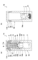
- FIG. 1 is a perspective view showing a sample storage device according to the first embodiment of the present invention.
- 2 (a) and 2 (b) are cross-sectional views showing a sample storage device according to the first embodiment of the present invention, and
- FIG. 2 (a) is an IIA-IIA of the first container shown in FIG.
- FIG. 2 (b) is a sectional view taken along line IIB-IIB of the second container shown in FIG.
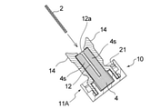
- FIG. 3 is a cross-sectional view showing the cap complex removed from the first container.
- FIG. 4 is a cross-sectional view showing a state in which the cap portion of the first container according to the first embodiment is attached to the container body of the second container, and is a view corresponding to FIG. 2A.
- FIG. 5 (a) to 5 (c) are views showing the cap complex removed from the first container
- FIG. 5 (a) is a perspective view
- FIG. 5 (b) is a cross section along the second direction Y
- FIG. 5 (c) is a cross-sectional view taken along the first direction X.
- FIG. 6 is a perspective view schematically showing how the liquid decomposition inhibitor is transferred from the agent holder to the medium holding the sample by using the cap complex according to the first embodiment.
- FIG. 7 is a cross-sectional view showing a sample storage device according to a second embodiment of the present invention, and is a view corresponding to FIG. 2 (a).
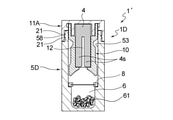
- FIG. 8 is a cross-sectional view showing a sample storage device according to a third embodiment of the present invention, and is a view corresponding to FIG. 2 (a).
- FIG. 9 is a cross-sectional view showing a sample storage device according to a fourth embodiment of the present invention, and is a view corresponding to FIG. 2 (a).
- 10 (a) to 10 (c) show a state in which the liquid decomposition inhibitor is transferred from the agent holder to the medium holding the sample by using the sample storage tool according to the fourth embodiment of the present invention. It is a diagram schematically shown, FIG. 10 (a) is a perspective view, and FIGS. 10 (b) and 10 (c) are sectional views.
- FIG. 10 (a) is a perspective view
- FIGS. 10 (b) and 10 (c) are sectional views.
- FIG. 11 is a perspective view showing a sample storage device according to a fifth embodiment of the present invention, and is a view corresponding to FIG. 1.
- 12 (a) and 12 (b) are views schematically showing the first container shown in FIG. 11, and FIG. 12 (a) is a sectional view taken along line XIIa-XIIA of the first container shown in FIG. 12 (b) is a plan view of the cap portion of the first container shown in FIG. 11 as viewed from the back surface side.
- FIG. 13 is a side view showing the second container shown in FIG. 11 with a partially broken portion.
- 14 (a) and 14 (b) show how the liquid decomposition inhibitor is transferred from the agent holder to the medium holding the sample by using the sample storage device according to the fifth embodiment of the present invention.
- FIG. 14 (a) is an exploded perspective view
- FIG. 14 (b) is a sectional view
- 15 (a) and 15 (b) are diagrams showing a sample storage device according to a fifth embodiment of the present invention
- FIG. 15 (a) is an exploded view
- FIG. 15 (b) shows a sample storage state.
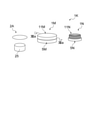
- FIG. 16 (a) and 16 (b) are views showing a sample storage device according to a sixth embodiment of the present invention
- FIG. 16 (a) is a view in which a container body and a cap portion are separated
- FIG. 16 ( b) is a cross-sectional view showing a sample storage state.
- the storage solution is used as it is in a liquid state.
- the medium from which the sample is collected is stored in the storage solution, for example, if the storage solution is an aqueous solution, the sample or the component to be inspected in the sample may be removed from the medium, or depending on the type of the component to be inspected in the sample. It may be unfavorable as a sample storage environment because it is easily decomposed by hydrolysis with water of the storage solution.
- the present invention relates to a sample storage tool that can solve the problems of the prior art.
- the sample storage tool 1 of the first embodiment includes a first container 1A and a second container 1B, and a medium in which the medium 2 holding the sample is housed in the first container 1A. It has a medium insertion unit 12 as a container, a liquid decomposition inhibitor 3 that suppresses decomposition of the sample to be inspected contained in the medium, and an agent holder 4 that can be impregnated with the decomposition inhibitor 3.
- the container 1B has a drying agent accommodating portion 6.
- FIG. 2 shows a state before the medium 2 holding the sample is housed in the medium insertion unit 12.
- the sample storage tool 1 stores the sample as a set containing the first container 1A and the second container 1B, more preferably a set containing the medium 2A capable of holding the sample in addition to the set of the first container 1A and the second container 1B. It is preferable to provide or distribute the ingredients to users.
- the user of the sample storage tool is a person who performs the work of accommodating the medium 2 holding the sample in the medium storage portion of the sample storage tool 1 so as to be stored in the sample storage tool 1, and is a doctor or a nurse. It is not limited to medical personnel such as researchers, and may be general consumers.
- the sample storage device of the present invention has the convenience of being safe to handle even by general consumers.
- the first container 1A and the second container 1B have an identification display 9 that makes it easy to distinguish between the two.
- the identification display 9 is provided by any method such as labeling and printing.
- the medium 2 holding the sample is housed in the medium insertion section (medium storage section) 12.
- the medium 2 holding the sample is a medium 2A capable of holding the sample, and the sample is held by an arbitrary method.
- the sample to be retained in the medium 2A is preferably a sample derived from an animal, and preferably contains a nucleic acid, a protein, a metabolite, or the like as a sample to be inspected.
- the animals referred to here include mammals including humans and non-human mammals, birds, reptiles, amphibians, fish, insects and the like. Examples of animal-derived specimens include skin surface lipids, saliva, blood, body fluids, and the like.
- the subject from which the sample is collected may be a living animal, a dead animal, or a non-living body to which a sample derived from the animal is attached, but it is possible to diagnose the health condition of various organisms. From the viewpoint of use for prediction and prediction, it is preferably a living body.
- Skin surface lipids are fat-soluble fractions present on the surface of the skin and are also called sebum.
- lipids on the surface of the skin are also referred to as "sebum".
- sebum mainly contains secretions secreted from exocrine glands such as sebaceous glands on the surface of the skin, and is present on the surface of the skin in the form of a thin layer covering the surface of the skin.
- the skin is a general term for regions including the epidermis, dermis, hair follicles, and tissues such as sweat glands, sebaceous glands, and other glands on the body surface, unless otherwise specified.
- the sebum contains nucleic acids derived from the cells of the subject from which the sebum is collected, particularly RNA (see Patent Document 1). Therefore, a typical example of the sample to be inspected when the sample is sebum is nucleic acid.
- RNA Ribonucleic acid
- the method for analyzing or analyzing the nucleic acid in the sample after storage is not particularly limited, and various known methods and the like can be used, and can be appropriately determined according to the purpose of analysis or analysis. Various known methods can also be used as a method for separating nucleic acid from a sample after storage with a sample storage tool.
- the sebum collected from the subject contains nucleic acids expressed in the skin cells of the subject, preferably containing nucleic acids expressed in any of the subject's epidermis, sebaceous glands, hair follicles, sweat glands, and dermis, more preferably. Contains nucleic acids expressed in any of the subject's dermis, sebaceous glands, hair follicles, and sweat glands.
- the nucleic acid derived from the subject's skin cells prepared from the specimen stored in the specimen storage device is preferably a nucleic acid derived from at least one site selected from the subject's epidermis, sebaceous gland, hair follicle, sweat gland and dermis.
- nucleic acid from at least one site selected from the epidermis, sebaceous glands, hair follicles and sweat glands is, for example, gene expression analysis and other genetic information analysis on the skin of the subject from which the sebum epidermal lipid is collected, functional analysis on the skin of the subject, and the subject's skin. It is useful as a sample for analysis of skin condition (for example, diagnosis of dermatitis), and analysis of the condition of a part other than the skin or the whole body of a subject (for example, diagnosis of various diseases).
- a method for analyzing or analyzing nucleic acid obtained from sebum for example, various methods described in Patent Document 1 can be used.
- the nucleic acid to be inspected may be either DNA or RNA, but RNA is preferable.
- RNA include mRNA, tRNA, rRNA, small RNA (for example, microRNA (miRNA), small interfering RNA (siRNA), Piwi-interacting RNA (piRNA), etc.), long intergenic non-coding (link) RNA, and the like.
- miRNA microRNA
- siRNA small interfering RNA
- piRNA Piwi-interacting RNA
- MiRNA is a small RNA having a length of about 19-30 nt among ncRNAs.
- LinkRNA is a long non-coding RNA having poly-A like mRNA, and has a length of 200 nt or more.
- the nucleic acid as a test component contained in the sample is preferably RNA having a length of 200 nt or more, and more preferably at least one selected from the group consisting of mRNA and lincRNA. Is.
- the first container 1A has a cap portion 11A and a container body 5A to which the cap portion 11A is mounted.
- the cap portion 11A is detachably attached to one end opening of the bottomed cylindrical container body 5A.
- the first container 1A has a medium insertion portion 12, a liquid decomposition inhibitor 3, and an agent holder 4.
- the agent holding body 4 is held by the cap portion 11A of the first container 1A, and even if the cap portion 11A is removed from the container body 5A, the state of being held by the cap portion 11A is maintained (see FIG. 3).
- the liquid decomposition inhibitor 3 is housed in the decomposition inhibitor storage section 31 provided in the container body 5A.
- the agent holding body 4 can be impregnated with the liquid decomposition inhibitor 3 and can maintain the impregnated state.
- the material for forming the agent holder 4 retains the liquid between the fibers (or in the pores) from the viewpoint of improving the retention of the liquid decomposition inhibitor 3 and the transferability of the liquid to the medium, but the material (fiber). ) Itself is preferably one that does not absorb liquid (moisture).
- the preferable forming material of the agent holding body 4 include a porous and flexible material, and examples thereof include felt, sponge, non-woven fabric and the like, or a laminate of one or more of these.
- the material for forming the agent holder 4 may be wool, wood pulp or the like in addition to the synthetic resin, but a material mainly composed of the synthetic resin is preferable in terms of containing no nucleic acid and drug resistance.
- the mass ratio of the synthetic resin is preferably 50% or more, preferably 90% or more, and more preferably 100% of the total mass.
- the medium 2 is inserted into the agent holder 4 as a medium accommodating portion for accommodating the medium 2 holding the sample.
- a medium insertion portion 12 for holding 2 is provided. It is preferable that the medium insertion unit 12 can hold the medium 2 simply by inserting the medium 2. More specifically, the medium insertion section 12 in the present embodiment will be described in more detail.
- FIG. 4s is provided, and when the medium 2 is inserted into the medium insertion portion 12, the medium 2 is stably held in the medium insertion portion 12 by receiving pressure from the pair of agent holding portions 4s and 4s. It has become like.
- the pair of agent holding portions 4s and 4s may be arranged in such a state that two independent agent holding bodies are arranged in close proximity or in contact with each other so that the medium insertion portion 12 is formed between them.
- one agent holding body 4 is provided with a slit-shaped notch, and the agent holding body 4 is the top surface portion 11a of the cap portion 11A.
- a non-divided portion 4r connecting the agent holding portions 4s and 4s is provided on the side.
- the facing surfaces 4a of the pair of agent holding portions 4s and 4s may or may not be in contact with each other in the state before the medium 2 is inserted into the medium inserting portion 12.
- the distance between the pair of phase-facing surfaces 4a should be appropriately determined in consideration of the thickness of the medium 2 when inserted into the medium insertion portion 12 and the transferability of the dispersion-suppressing liquid from the agent holder 4 to the medium 2.
- the shape of the medium 2A for holding the sample can be any shape such as a sheet shape, a block shape, a spherical shape with a handle, and the like, but as shown in FIG. 1, it is preferably a sheet shape.
- the sheet-shaped medium 2A preferably has flexibility and is preferably foldable.
- the sheet-shaped medium 2A has a smaller shape during storage than the area at the time of collection by folding the sample after holding it, or from the viewpoint of collection efficiency and workability when collecting the sample from the skin of an animal. It is preferable from the viewpoint of being able to do it. Further, when collecting a sample from the skin of a human or a non-human animal, using the sheet-shaped medium 2A has an advantage that the sheet can be deformed at the time of collection to reduce the irritation to the skin.
- a porous sheet can also be used as the sheet-shaped medium 2A. It is preferable to use a porous sheet because the sample is adsorbed on the micropores of the sheet and the sample can be held more firmly on the sheet.
- the sheet-shaped medium 2 after holding the sample can be stored in the medium insertion section 12 in a folded state a plurality of times, which makes it possible to reduce the size of the sample storage tool 1 and improve the transportability and handleability. It is preferable from the viewpoint of making it.
- the distance between the inner surfaces 4a of the agent holding portions 4s and 4s facing each other across the medium inserting portion 12 is such that the medium 2A can be easily inserted and the medium 2 can be separated from the fingers or instruments that were in contact with the medium 2A at the time of insertion. It can be appropriately set from the viewpoint of maintaining stability in the medium insertion portion 12, and is, for example, 0 mm or more and 10 mm or less, preferably 0 mm or more and 7 mm or less.
- the distance between the inner surfaces 4a of the pair of agent holding portions 4s and 4s is measured in the natural state before the medium 2 is inserted.
- a method capable of holding the sample can be used without particular limitation depending on the type of the sample.
- a method of collecting sebum as a sample a method of directly contacting the skin with a medium 2A capable of holding the sample, a method of collecting the sample by rubbing the sample collected using an instrument such as a spatula or a scraper against the medium 2A, or the like.
- the medium 2A capable of holding the sample is preferably one having a high adsorbability of the sample depending on the sample, and more preferably a sheet-shaped sample adsorbent is used.
- the sheet-shaped sample adsorbent when the sample is sebum
- a sheet-like material having sebum-adsorbing properties such as oil-blotting paper and oil-blotting film can be used.
- a sheet-like material containing a highly fat-soluble solvent in advance can also be used.
- the sheet-shaped medium 2A contains a highly water-soluble solvent or water, the adsorption of sebum is suppressed, so that the sheet-shaped medium 2A is preferably used in a dry state.
- the first container 1A of the present embodiment includes a pair of outer support portions 14 that cover the outer surface 4b side of the agent holder 4 on both sides of the medium insertion portion 12. More specifically, the first container 1A includes a support portion forming member 15 coupled to the cap portion 11A.
- the support portion forming member 15 is a member that supports the agent holding body 4 in a state of being held by the cap portion 11A, and a part thereof forms a pair of outer support portions 14.
- the cap portion 11A, the agent holding body 4, and the support portion forming member 15 form a cap portion complex 10 that can be integrally handled with the cap portion 11A when the cap portion 11A is removed from the container body 5A. ..
- the support portion forming member 15 has a base portion 16 located on the connection portion side with the cap portion 11A and a pair of outer support portions 14 branching and extending in two toward the tip end side in the direction protruding from the cap portion 11A. , 14 and are provided.
- the base portion 16 of the support portion forming member 15 is fixed to the cap portion 11A.
- the tubular connecting portion 16a formed in the lower part of the base portion 16 is fixed to the cap portion 11A by fitting with the tubular connecting portion 11b formed on the inner surface side of the top surface portion 11a of the cap portion 11A. Has been done.
- the first container 1A has a pair of outer support portions 14 sandwiched between fingers to increase or decrease the pressing force so that the medium 2 inserted into the medium insertion portion 12 can be inserted into the medium 2.
- the pressure for pressing the agent holder 4 can be increased or decreased.
- the entire support portion forming member 15 or the outer support portion 14 is provided with a relatively flexible synthetic resin such as polyethylene, polyester, polypropylene, polyamide-based synthetic resin, elastomer, rubber, or a composite material of two or more thereof.
- the pressure can be adjusted by configuring it with a material selected from.
- the pair of outer support portions 14 and 14 have a flexible portion 19 on the proximal end side thereof. It is preferable to have.
- the flexible portion 19 is a portion that serves as a base point for bending or bending of the outer support portion 14, and is preferably elastically deformable.
- the flexible portion 19 can be formed by partially forming the support portion forming member 15 into a thin wall or the like. Further, the flexible portion 19 can also be formed by providing a hinge structure in a part of the support portion forming member 15.
- FIG. 6 shows a state in which the pair of outer support portions 14, 14 are sandwiched between the thumb and the index finger.
- the pair of outer support portions 14, 14 are on the inner surface 14a, which is the surface on the medium insertion portion 12, and the side opposite to the medium insertion portion 12, respectively. It has an outer surface 14b located and a tip surface 14c located on the side opposite to the cap portion 11A side in the height direction Z of the cap portion composite 10.
- a holding recess 14d of the agent holding portion 4s is formed on the inner surface 14a side of each of the pair of outer supporting portions 14 and 14. Since a part of the agent holding portion 4s is housed in the holding recess 14d, the agent holding portion 4s is stably held at a predetermined position of the outer support portion 14.
- the agent holding portion 4s housed in the holding recess 14d is fixed in the holding recess 14d by any means such as adhesion by an adhesive, heat fusion, fitting, and engagement of engaging protrusions. May be good.
- the cross-sectional shape of the holding recess 14d and the agent holding portion 4s, which is orthogonal to the height direction Z of the cap portion composite 10, may be any shape such as a semicircle, a rectangle, or a triangle.
- the agent holding portions 4s and 4s shown in FIG. 5B each have a rectangular cross-sectional shape, and the facing inner surfaces 4a are substantially flat surfaces parallel to each other, but are limited thereto. Instead, for example, the opposing inner surfaces 4a of the agent holding portions 4s, 4s may be curved along one or both of the height direction Z and the first direction X of the cap portion complex 10.
- each of the pair of agent holding portions 4s a part of the outer surface side of the agent holding portion 4s is accommodated in the holding recess 14d, and the pair of agent holding portions 4s is the side accommodated in the holding recess 14d of the agent holding body.
- the opposite side protrudes from the holding recess 14d. That is, the surface of the agent holding portion 4s on the side opposite to the side housed in the holding recess 14d and the inner surface 14a of the outer support portion 14 that supports the agent holding portion 4s are not flush with each other, but the agent holding portion.
- the surface opposite to the side housed in the holding recess 14d in 4s is located closer to the medium insertion portion 12 than the inner surface 14a.
- the height direction Z of the cap portion composite 10 is such that the side where the support portion forming member 15 protrudes from the cap portion 11A is the upper side in the vertical direction and the cap portion.
- the direction is along the vertical direction.
- the direction in which the medium 2 is moved when the medium 2 is accommodated in the medium insertion portion 12 is substantially parallel to the direction in which the medium 2 is moved.
- the second direction Y of the cap portion complex 10 is a direction orthogonal to the height direction Z of the cap portion complex 10, and when the cap portion complex 10 is viewed in a plan view from one side of the height direction Z,
- the pair of outer support portions 14, 14 or the inner surfaces 4a of the agent holding portions 4s, 4s are opposed to each other, and the first direction X of the cap portion composite 10 is the height of the cap portion composite 10. It is a direction orthogonal to the direction Z, and is a direction orthogonal to the second direction Y when the cap portion complex 10 is viewed in a plan view from one side of the height direction Z.
- the support portion forming member 15 in the present embodiment has a liquid leakage prevention groove 17 on the inner surface 14a side of each of the pair of outer support portions 14, 14 as shown in FIG. 5 (c).
- the liquid leakage prevention groove 17 is formed on both sides of the outer support portion 14 so as to sandwich the holding recess 14d.
- the inner surface 14a of the outer support portion 14 is a flat surface on both sides of the holding recess 14d, and the liquid leakage prevention groove 17 is formed on the flat surface.
- the liquid leakage prevention groove 17 extends along the height direction Z of the cap portion composite 10. Further, the liquid leakage prevention groove 17 is terminated at a position that does not reach the upper ends of the opposite inner surfaces of the pair of outer support portions 14, 14.
- the support portion forming member 15 resupply the liquid that has passed through the liquid leakage prevention groove 17 to the agent holding portion 4s on the base end side of the cap portion composite 10 in the height direction Z.
- the lower end side of the liquid leakage prevention groove 17 is formed inside the tubular connection portion 11b via the through hole 17a formed in the base portion 16 of the support portion forming member 15, and the liquid resupply space 18 is formed. Communicate with.
- the undivided portion 4r of the pair of agent holding portions 4s and 4s is located in the liquid resupply space 18, and during the operation of transferring the liquid decomposition inhibitor 3 from the agent holding body 4 to the medium 2.
- the liquid that entered the liquid leakage prevention groove 17 without remaining in the state where the liquid decomposition inhibitor 3 discharged from the agent holding portion 4s adhered to the medium 2 is a liquid as shown by an arrow a in FIG. 5 (c).
- the leak prevention groove 17, the through hole 17a, and the undivided portion 4r flow through the liquid resupply path and are resupplied to the agent holding body 4.
- the cap portion complex 10 is inclined to guide the medium 2 to be inserted into the medium insertion portion 12 toward the insertion port 12a of the medium insertion portion 12 in the vicinity of the upper ends of the pair of outer support portions 14, 14 respectively. It has a guide surface 141.
- the support portion forming member 15 has a pair of inclined guide surfaces 141 on both sides of the central portion of the first direction X, and each of the pair of inclined guide surfaces 141 is in the height direction of the support portion forming member 15. It has a reverse-tapered shape in which the separation distance between the two decreases as the position of is lowered.
- a concave curved surface portion 142 having a shape along the convex curved surface portion of the inner plug 54, which will be described later, is provided.
- the inclined guide surface 141 is preferably located on the upper end side of the support portion forming member 15 with respect to the insertion port 12a.
- the sample storage tool 1 of the present embodiment has a storage portion 31 of a liquid decomposition inhibitor 3 inside the container body 5A of the first container 1A. Further, the first container 1A is provided with a partition portion 50 for partitioning the internal space of the liquid decomposition inhibitor 3 into a storage portion 31 and a storage portion 53 of the agent holder 4 and the outer support portion 14. A through hole 54d penetrating the partition portion 50 is formed in the partition portion 50. The through hole 54d functions as an agent supply hole for supplying the decomposition inhibitor 3 in the storage unit 31 to the agent holder 4 by the user of the sample storage tool 1 performing a predetermined operation.
- the predetermined operation in the present embodiment is that the cap portion 11A is placed on the upper side in the vertical direction and the bottom portion of the container body 5A is placed on the lower side in the vertical direction.
- an operation of shaking the first container 1A up and down can be mentioned.
- the first container 1A has the storage portion 31 of the decomposition inhibitor 3 and the agent holder 4 in a state of being separated internally, and the decomposition inhibitor 3 is operated until the storage portion 31 performs a predetermined operation.
- the fact that the agent holder 4 and the agent holder 4 can be maintained in a separated state can be stored in a more stable state, for example, the risk of volatilization and precipitation of the components of the decomposition inhibitor 3 can be reduced.
- the agent holding body 4 is provided in the cap portion 11A of the self-supporting container, and the liquid decomposition inhibitor storage portion may be provided in a portion vertically separated from the agent holding body 4.
- the partition portion 50 in the present embodiment is formed by arranging an inner plug 54 in the container main body 5A.
- the inner plug 54 is in contact with the cylindrical portion 54a having an outer peripheral surface shape that matches the inner peripheral surface shape of the container body 5A and the step portion 55 formed on the inner peripheral surface of the container body 5A, and the mounting position of the inner plug 54.
- the annular overhanging portion 54b has a dome-shaped tip-retracted portion 54c whose inner diameter and outer diameter gradually decrease toward one end opening side of the container body 5A, and the tip-retracted portion 54c.
- the through hole 54d is formed at the top.
- the partition portion 50 has a pair of the partition portions 50 having the facing surface side of the agent holding body 4 of the tip-squeezed shape portion 54c in the above-mentioned outer support portion 14. It is preferable that the shape is formed along the inclined guide surface 141 of the above. From the same viewpoint, it is preferable that the partition portion 50 and the inner plug 54 are formed so that the position of the through hole 54d faces the medium insertion portion 12 in the agent holder 4. Further, from the viewpoint of preventing the decomposition inhibitor 3 in the storage portion 31 from migrating to the agent holder 4 until the user intentionally performs a predetermined operation, the agent supply hole is formed in the inner plug 54.
- the opening area of the through hole 54d is preferably smaller than the opening area on the storage portion 31 side of the inner plug 54, and the opening area of the through hole 54d (agent supply hole) of the inner plug 54 is stored. It is preferably 10% or less, more preferably 5% or less of the opening area on the portion 31 side.
- the second container 1B in the first embodiment has a cap portion 11B and a container body 5B to which the cap portion 11B is mounted.
- the container body 5B of the second container 1B can be attached with the cap portion 11A removed from the container body 5A of the first container 1A.
- the container body 5B of the second container 1B before mounting the cap portion 11A of the first container 1A has a cap portion different from the cap portion 11A of the first container 1A. It is preferable to attach 11B and close the opening of the container body 5B.
- the cap portion 11B of the second container 1B in the present embodiment is detachably or detachably attached to one end opening of the container body 5B.
- the container body 5B in the second container 1B is not formed with the agent holding body 4, the support portion forming member 15, the inner plug 54, and the decomposition inhibitor storage portion 31 in the first container 1A, but instead is a desiccant.
- the cap portion 11A is removed from the container body 5A in the first container 1A, the medium 2 holding the sample is inserted into the medium insertion portion 12 attached to the cap portion 11A, and then the cap portion is inserted.
- a storage container 1C in which the cap portion 11A of the first container 1A and the container body 5B of the second container 1B are combined can be obtained. can.
- threads 21 and 58 are provided on the inner peripheral surface of the cap portion 11A and the outer peripheral surface of one end opening of the container body 5A, and the cap portion 11A is screwed into the container body 5A. Further, a sealing member such as packing (not shown) is arranged at the abutting portion between the cap portion 11A and the container body 5A and the abutting portion between the cap portion 11B and the container body 5B.
- the insides of the first container 1A, the second container 1B, and the storage container 1C can be hermetically sealed.
- the method of attaching the cap portions 11A and 11B to the container body 5A or the container body 5B is not limited to screwing, and any configuration such as engagement and fitting may be adopted.
- the desiccant accommodating portion 6 in the second container 1B is formed near the bottom of the container body 5B, and as shown in FIG. 4, the first container 1A to which the medium 2 holding the sample and the agent holder 4 are attached.
- the contact suppressing member 7 is located between the agent holding body 4 and the desiccant accommodating portion 6, and the desiccant 61 in the accommodating portion 6 is located. , It is designed so that it does not come into direct contact with the agent holder 4.
- the contact suppressing member 7 can isolate the desiccant 61 and the agent holding body 4 so as not to come into direct contact with each other, while being released from the agent holding body 4 or the decomposition suppressing agent transferred from the agent holding body 4 to the medium 2. Any form of any material can be used as long as it is capable of absorbing moisture and can achieve such purpose.
- the contact suppressing member 7 is a material that does not hinder the air permeability between the desiccant of the desiccant accommodating portion 6 and the agent holder 4. Examples of the contact suppressing member 7 include a porous member fixed at a predetermined height position in the internal space of the container body 5B, an inner plug, a cotton-like body made of synthetic resin, a sheet-like member having air permeability, and the like.
- the desiccant 61 one capable of absorbing the moisture and moisture released from the decomposition inhibitor can be used without particular limitation.
- a physical desiccant such as silica gel, aluminum oxide, molecular sieve, or zeolite, or a chemical desiccant such as fresh lime or calcium chloride can be used.
- the desiccant 61 may be used alone or in combination of two or more.
- the chemical desiccant is accompanied by a change in the substance when it is dried, while the physical desiccant does not change the substance and adsorbs water molecules on the porous surface. Therefore, the desiccant 61 can be used as a sample or a medium.
- a physical desiccant such as molecular sieve.
- a solution of the decomposition inhibitor 3 having a function of suppressing the decomposition of the component to be inspected that may be contained in the medium can be used without particular limitation.
- the sample contains an enzyme that decomposes the component to be inspected
- various liquid agents that can inhibit or inactivate the activity of the enzyme can be used.
- the sebum may contain a nucleic acid degrading enzyme derived from a subject or other germs. By inactivating such a nucleic acid degrading enzyme, the degradation of the nucleic acid contained in the sample can be suppressed.
- an aqueous solution containing guanidine hydrochloride, guanidine thiocyanate, urea, or thiourea which are chaotropic modifiers, can be used. Since it is not preferable for an aqueous solution containing guanidine hydrochloride or the like to come into contact with the body, when such a decomposition inhibitor is used, the use of the sample storage device 1 of the present invention is from the viewpoint of suppressing adhesion to the body. It is even more useful.
- the amount of the decomposition inhibitor 3 contained in the first container 1A can be appropriately determined according to the size of the medium 2 and the like. For example, FIG. 2A shows a state in which about 1 to 2 mL of the liquid decomposition inhibitor 3 is contained.
- the medium 2A holds a sample such as sebum by an appropriate method such as wiping the surface of the subject with a medium 2A capable of holding the sample.
- the medium 2A is folded a plurality of times to form a compact form.
- the agent holding body 4 is impregnated with the decomposition inhibitor 3 contained in the storage portion 31 in the first container 1A by a predetermined operation such as inverting the first container 1A and shaking it up and down a plurality of times.
- the cap portion 11A is removed from the container body 5A in the first container 1A, and the medium 2 holding the sample is inserted into the medium insertion portion 12 provided in the agent holder 4 attached to the cap portion 11A. Since the agent holding body 4 is impregnated with the liquid decomposition inhibitor 3, the liquid decomposition inhibitor 3 becomes efficient by inserting the medium 2 into the medium inserting portion 12 formed in the agent holding body 4. To move to medium 2. In a state where the medium 2 is inserted into the medium insertion portion 12, the outer support portions 14 and 14 are sandwiched between the fingers and the outer support portions 14 and 14 are pressed to decompose the liquid impregnated in the agent holder 4. The inhibitor 3 can be more effectively transferred to the medium 2 and the sample held in the medium 2. Further, by sandwiching the outer support portions 14 and 14 between the fingers and repeatedly increasing or decreasing the pressing force, the liquid decomposition inhibitor 3 impregnated in the agent holder 4 is transferred to the medium 2 more reliably and efficiently. Can be done.
- 11A is attached.
- the liquid decomposition inhibitor 3 is released from the agent holder 4. Since it can be transferred to the medium 2, decomposition of the test component in the sample contained in the medium 2 can be suppressed. Further, it is preferable to use the liquid decomposition inhibitor 3 from the viewpoint that the agent holder 4 can be efficiently impregnated and the impregnated decomposition inhibitor 3 can be efficiently transferred to the medium 2. Moreover, instead of bringing the liquid decomposition inhibitor 3 into direct contact with the medium 2 or the sample, the medium 2 comes into contact with the agent holder 4 impregnated with the liquid decomposition inhibitor 3 and the decomposition inhibitor comes into contact with the medium 2. Since 3 is arranged to migrate, it is possible to prevent the liquid decomposition inhibitor 3 from spilling or scattering to the surroundings during the work of bringing the decomposition inhibitor 3 into contact with the medium 2.
- the cap portion 11A after the medium 2 is inserted into the medium insertion portion 12 is mounted in the storage container 1C generated by attaching the cap portion 11A to the container body 5B of the second container 1B.
- the decomposition inhibitor 3 is used by the desiccant 61 without directly contacting the desiccant 61 with the agent holder 4. It can absorb the moisture released from. As a result, the amount of water in the liquid decomposition inhibitor remaining in the agent holder 4 can be reduced without directly contacting the desiccant 61 with the liquid decomposition inhibitor remaining in the agent holder 4, for example.
- the liquid decomposition inhibitor 3 is impregnated into the agent holder 4 and brought into contact with the medium 2 so that the liquid decomposition inhibitor 3 can be brought into contact with the body of the liquid decomposition inhibitor 3. Contact can be prevented, and by reducing the water content in the liquid decomposition inhibitor after storage in the medium, leakage of the liquid decomposition inhibitor and decomposition of the component to be inspected in the sample can be more effectively suppressed. Can be done. Further, according to the sample storage tool 1 of the first embodiment, no cooling facility is required, and the workability of storing and transporting the sample is excellent.
- the second container 1B has a contact suppressing member 7 which is arranged between the desiccant accommodating portion 6 and the agent holder 4 to prevent contact between the desiccant 61 and the agent holder 4, and has a desiccant.
- the fact that the 61 is not brought into direct contact with the agent holder 4 may occur depending on the combination of the liquid decomposition inhibitor 3 and the desiccant 61, such as heat generation caused by the direct contact between the aqueous solution of guanidine hydrochloride and the molecular sieve.
- heat generation caused by the direct contact between the aqueous solution of guanidine hydrochloride and the molecular sieve.
- the sample storage device of the second to seventh embodiments of the present invention will be described.
- the second to fifth embodiments will be described with reference to differences from the first embodiment, and the same reference numerals will be given and the description thereof will be omitted.
- the sample storage device of the second embodiment is different from the first embodiment in that it includes the first container 1A'shown in FIG. 7 instead of the first container 1A shown in FIG. 2 (a).
- the first container 1A'shown in FIG. 7 does not have an inner plug inside, and a liquid decomposition inhibitor is held in a state of being impregnated in the agent holder 4.
- the cap portion 11A is removed from the container body 5A'of the first container 1A'and the medium 2 holding the sample is inserted into the medium insertion portion 12 attached to the cap portion 11A.
- the cap portion 11A By attaching the cap portion 11A to one end opening of the container body 5B of the second container 1B as in the first embodiment, the cap portion 11A of the first container 1A'and the container of the second container 1B are attached. It can be a storage container combined with the main body 5B. According to the second embodiment, the same effect as that of the first embodiment is exhibited except for the effect of separating the decomposition inhibitor and the agent holder before use.
- the height of the first container 1A'in the second embodiment is different from that of the second container 1B, it is easier to distinguish between the first container 1A'and the second container 1B, and confusion is more reliably prevented. can.
- the height of the first container 1A'and the height of the second container 1B may be the same.
- the sample storage tool 1'of the third embodiment has a medium insertion unit 12 as a medium storage unit and a liquid that suppresses decomposition of the sample to be inspected contained in the medium in a single container 1D. It has a decomposition inhibitor 3 of the above, an agent holder 4 capable of impregnating the decomposition inhibitor 3, and a desiccant accommodating portion 6.
- the container 1D has a cap portion 11A for holding the agent holding body 4 and a container body 5D to which the cap portion 11A is detachably attached.
- the medium insertion portion 12 is provided in the agent holding body 4 held by the cap portion 11A.
- the agent holder 4 is impregnated with an appropriate amount of the decomposition inhibitor 3 in advance before the sample storage tool is used.
- a partition member 8 for preventing contact between the desiccant 61 in the accommodating portion 6 and the agent holding body 4 is arranged inside the container body 5D.
- the partition member 8 airtightly partitions between the agent holding body 4 and the desiccant accommodating portion 6, and the moisture in the decomposition inhibitor impregnated in the agent holding body 4 is removed by the desiccant 61 before use. It is designed not to be absorbed. As a result, the decomposition inhibitor is maintained in a liquid state, and the transfer of the decomposition inhibitor from the agent holder 4 to the medium 2 becomes good.
- the partition member 8 is, for example, an annular member provided with a thin film made of synthetic resin in the central portion.
- the cap portion 11A is removed from the container body 5D, and the medium insertion portion 12 of the agent holder 4 impregnated with the liquid decomposition inhibitor 3 in advance is used.
- the medium 2 is folded to an appropriate size and inserted, and if desired, the outer support portions 14 and 14 are pressed by hand to press the medium 2 from the agent holding body 4. Promotes the transfer of the decomposition inhibitor 3 to.
- a through hole is formed in the partition member 8 in the container body 5D from which the cap portion 11A is removed by using an appropriate puncture tool such as a toothpick or a dedicated puncture tool supplied as a set with the sample storage tool 1'.
- the partition member 8 having the through hole formed functions as a contact suppressing member.
- the cap portion 11A holding the medium 2 in the medium insertion portion 12 is attached to the container body 5D.
- the medium 2 is arranged in the medium insertion section (medium accommodating section) 12 under the state where the agent holder 4 is impregnated with the liquid decomposition inhibitor 3.
- the decomposition inhibitor 3 is transferred to the medium 2
- the desiccant 61 is transferred to the agent holder 4 while the medium 2 is housed in the medium insertion portion (medium accommodating portion) 12.
- the moisture released from the decomposition inhibitor 3 can be absorbed without direct contact. Therefore, according to the sample storage tool 1'of the third embodiment, the same effect as that of the sample storage tool of the first or second embodiment is exhibited. Further, since two containers, a first container and a second container, are not required, it is advantageous in terms of transportation, storage, handling and the like.
- the sample storage tool 1 "of the fourth embodiment includes a container 1E having a cap portion 11E and a container body 5E to which the cap portion is attached.
- the cap portion 11E is a bottomed cylinder. It is detachably attached to one end opening of the shaped container body 5E.
- the cap portion 11E is provided with a bottomed tubular desiccant accommodating body 60 having a desiccant accommodating portion 6 inside.
- the desiccant container 60 functions as a contact suppressing member that suppresses direct contact between the agent holder 4 impregnated with the liquid decomposition inhibitor and the desiccant 61.
- an agent holder 4 in a state of being impregnated with a liquid decomposition inhibitor is arranged inside the container body 5E.
- the agent holding body 4 has a portion arranged along the upper surface of the bottom portion of the container body 5E and the inner peripheral surface near the bottom portion. Then, as shown in FIG. 9, between the desiccant accommodating body 60 and the agent holding body 4 in a state where the cap portion 11E is attached to the container body 5E, the medium accommodating the medium 2 holding the sample is accommodated. It is part 12E.
- the desiccant container 60 is made of an agent-impermeable material that does not allow the decomposition inhibitor to permeate, and a ventilation hole 63 that communicates the inside and outside of the desiccant storage portion 6 is formed at a portion that does not come into contact with the medium 2.
- the ventilation hole 63 is closed with a seal or the like (not shown) in the state before inserting the medium, and after removing the cap portion 11E, the seal or the like can be removed before accommodating the medium 2 to allow ventilation. It is in a state of being.
- the ventilation hole 63 is formed in a portion of the desiccant container 60 on the cap portion 11E side.
- a plurality of ventilation holes 63 are formed around the desiccant container 60 so as to be spaced apart from each other in the circumferential direction. The number of ventilation holes 63 may be only one.
- the sample storage tool 1 "of the fourth embodiment As shown in FIG. 10A, after removing the cap portion 11E from the container body 5E and holding the sample in the sheet-shaped medium 2A'.
- the medium 2 folded to an appropriate size is positioned below the bottom 62 of the desiccant container 60 attached to the cap portion 11E, and as shown in FIG. 10 (b), the medium 2 is housed in the desiccant.
- the body 60 is pushed into the container body 5E, and as shown in FIG. 10 (c), the medium 2 is pressed against the agent holding body 4 by the desiccant container 60 to be brought into close contact with the container body 4, and the cap portion 11E is attached to the container body 5E.
- the space inside the container 1E is sealed.
- the medium 2 can be arranged in the medium storage unit 12E under the state where the agent holder 4 is impregnated with the liquid decomposition inhibitor 3, thereby.
- the decomposition inhibitor 3 is transferred to the medium 2.
- the desiccant 61 allows the moisture released from the decomposition inhibitor 3 to pass through the container 1E whose inside is closed. It is absorbed through the pores 63 without directly contacting the agent holder 4.
- the sample storage device 1 of the fourth embodiment the sample storage device of the first to third embodiments is used. A similar effect is achieved.
- the sheet-shaped medium 2 is wrapped around the lower part of the desiccant container 60.
- the medium 2 may be pushed into the space surrounded by the agent holding body 4 in the container body 5E and brought into close contact with the agent holding body 4.
- FIG. 11 is a diagram showing a sample storage device 1K according to a fifth embodiment of the present invention.
- the sample storage tool 1K of the fifth embodiment includes a first container 1M having a cap portion 11M and a container body 5M to which the cap portion 11M is mounted, and an inner container 5N housed in the first container 1M. There is.
- the inner container 5N is combined with the cap portion 11N to form the second container 1N.
- the sample storage tool 1K of the fifth embodiment is preferably provided to the user as a set of the first container 1M and the second container 1N.
- the sample storage tool 1K of the fifth embodiment has an agent holder 4 capable of containing a liquid decomposition inhibitor in the first container 1M, and a part of the inner container 5N is a desiccant accommodating portion 6. It is a desiccant container 60 having the above.
- the cap portion 11M is removed from the container body 5M in the first container 1M, and the container body 5M is housed in a holding body.
- the medium 2 holding the sample is placed on the agent holder 4 housed in the part 51, and the inner container 5N containing the desiccant 61 is placed in the container container 52 of the container body 5M, and then the second container is placed.
- a storage container 1G in which the inner container 5N is housed in the first container 1M can be obtained.
- the first container 1M has a cap portion 11M and a container body 5M on which the cap portion 11M is mounted.
- the cap portion 11M is detachably attached to one end opening of the bottomed cylindrical container body 5M.
- the cap portion 11M has a sealing member 41 on the back surface 30b side of the top surface portion 31m.
- the seal member 41 has a plan view shape along the peripheral shape of the opening of the inner container 5N, and has a substantially circular annular shape.
- the seal member 41 is arranged on the peripheral edge of the top surface portion 31 m of the cap portion 11M.
- Examples of the sealing member 41 include packings made of materials such as rubber, silicon, elastomer, polyethylene, foamed polyethylene, polypropylene, and foamed polypropylene.
- the cap portion 11M has a ridge portion 33 protruding from the back surface 31b of the top surface portion 31m.
- the ridge 33 extends along one direction.
- the ridge portion 33 is arranged in the region surrounded by the seal member 41.
- the end portion 33a in the longitudinal direction of the ridge portion 33 does not reach the seal member 41.
- a gap is formed between the longitudinal end 33a of the ridge 33 and the seal member 41.
- the cap portion 11M may have only one ridge portion 33, or may have a plurality of ridge portions 33.
- the directions in which the plurality of convex portions 33 extend may intersect each other, or are substantially parallel to each other as shown in FIG. 12 (b). May be good.
- the container body 5M has a holding body accommodating portion 51 capable of accommodating the agent holding body 4 and a container accommodating portion 52 capable of accommodating the inner container 5N.
- the container accommodating portion 52 is located closer to the opening side of the container body 5M than the holding body accommodating portion 51.
- the holding body accommodating portion 51 is a space surrounded by a first peripheral wall portion 51b erected from the bottom portion 51a and the peripheral portion of the bottom portion 51a of the container body 5M.
- the container accommodating portion 52 is a space surrounded by a second peripheral wall portion 52b located on the opening side of the container main body 5M with respect to the first peripheral wall portion 51b.
- the second peripheral wall portion 52b has a larger diameter than the first peripheral wall portion 51b.
- the lower end of the second peripheral wall portion 52b and the upper end portion of the first peripheral wall portion 51b are connected by a connecting portion 56.
- the second container 1N has a cap portion 11N and an inner container 5N to which the cap portion 11N is mounted.
- the cap portion 11N is detachably attached to the opening of the bottomed cylindrical inner container 5N.
- the inner container 5N is adapted to be accommodated in the container accommodating portion 52 of the container body 5M of the first container 1M (see FIGS. 14 (a) and 14 (b)). Further, as shown in FIG. 13, the inner container 5N has a desiccant container 60 having a desiccant container 6 inside.
- the desiccant container 60 is a contact suppressing member that suppresses direct contact between the agent holding body 4 impregnated with the liquid decomposition inhibitor and the desiccant 61 when placed in the container body 5M of the first container 1M. Functions as.
- the inner container 5N has a container peripheral wall portion 71 in addition to the desiccant container 60. The container peripheral wall portion 71 is located outside the inner container 5N in the radial direction with respect to the desiccant container 60.
- the cap portion 11N has a top surface portion 31n and a peripheral wall portion 32n extending from the peripheral portion of the top surface portion 31n.
- the peripheral wall portion 32n extends from the peripheral edge portion of the top surface portion 31n toward both sides of the cap portion 11N in the height direction H.
- the peripheral wall portion 32n includes an upper peripheral wall portion 32u located above the top surface portion 31n in the height direction H and a lower peripheral wall portion 32d located below the top surface portion 31n in the height direction H. including.
- the length of the peripheral wall portion 32n in the height direction H is used. It can be long enough for a person to grip the peripheral wall portion 32n.
- the peripheral wall portion 32n can be gripped and the cap portion 11N can be rotated with respect to the inner container 5N. It will be easier. From the viewpoint of making it easier for the user to grip the peripheral wall portion 32n, it is preferable that the peripheral wall portion 32 has a rib 31r on its outer surface as shown in FIGS. 11 and 13.
- the inner container 5N is housed in the container body 5M and the cap portion 11M is attached to the container body 5M.
- the medium accommodating portion 12 is formed between the desiccant accommodating body 60 and the agent holding body 4.
- the medium storage unit in the sample storage device of the present invention is not limited to the one formed from the beginning like the medium insertion unit 12 of the first embodiment, and a plurality of members constituting the sample storage device 1K may be combined. For example, those formed by combining the first container 1M and the inner container 5N in the present embodiment are also included.
- the cap portion 11M is removed from the container body 5M in the first container 1M, and the desiccant container 60 and the agent holding are held. After the medium 2 is arranged between the body 4 and the body 4, the medium 2 is brought into close contact with the agent holding body 4 by attaching the cap portion 11M to the container body 5M.
- the medium 2A holds a sample such as sebum by an appropriate method such as wiping the surface of the subject with a medium 2A capable of holding the sample. It is also preferable to use an auxiliary tool 25 capable of detachably holding the medium 2A when performing an operation such as wiping the surface of the subject with the medium 2A.
- the auxiliary tool 25 By using the auxiliary tool 25, the user can perform an operation such as grasping the auxiliary tool 25 and wiping the surface of the subject without directly grasping the medium 2A. Therefore, the medium 2A is other than the sample. It is possible to prevent things from adhering.
- the auxiliary tool 25 preferably has a cushioning property. Further, it is preferable that the auxiliary tool 25 can adhere the medium 2A without using an adhesive.
- various synthetic resin foams having cushioning properties can be used, and preferably, a material having a suction cup structure or the like having a large number of recesses on the surface where the inside is depressurized by pressure contact is used.
- a material bonded to a material having cushioning properties can be used. Examples of the material having cushioning properties include foams of elastic resin, and specifically, ethylene / propylene / diene copolymer (EPDM), NBR, PE, PP, PET, SBR, elastomer, silicon rubber and the like.
- EPDM ethylene / propylene / diene copolymer
- Examples thereof include a foam containing the above as a raw material.
- the material having cushioning property shall be a constituent material to be used by selecting a synthetic resin having an elastic restoring force against compression, a sponge made of a natural material, a non-woven fabric, a woven fabric, or a composite material of two or more of these. Is preferable.
- Examples of the material having a suction cup structure include an acrylic resin and the like.
- the shape of the auxiliary tool 25 capable of holding the medium 2A is not particularly limited, and examples thereof include a rectangular parallelepiped, a columnar body, and a hemispherical body.
- the columnar body or the like may have a flat shape as shown in FIG.
- the cross-sectional shape of the rectangular parallelepiped or the columnar body is not particularly limited, and may be a circular shape (see FIG. 11), an elliptical shape, a rectangular shape, a rhombus shape, or the like.
- the cap portion 11M is removed from the container body 5M in the first container 1M, and the medium 2 holding the sample is placed on the agent holding body 4 impregnated with the decomposition inhibitor 3 (FIGS. 14A and 14B). )reference).
- the medium 2 is held by the auxiliary tool 25, the medium 2 is removed from the auxiliary tool 25 and the medium 2 is placed on the agent holding body 4.
- the inner container 5N of the second container 1N containing the desiccant 61 from which the cap portion 11N has been removed is placed in the container storage portion 52 of the container body 5M of the first container 1M (FIG. 14 (a). ) And (b)).
- the inner container 5N in the container accommodating portion 52, the medium 2 is arranged between the accommodating portion 6 of the desiccant 61 and the agent holding body 4.
- the medium 2 comes into close contact with the agent holding body 4. More specifically, when the cap portion 11M is attached to the container body 5M, the top surface portion 31m of the cap portion 11M abuts on the upper end portion 60a of the desiccant accommodating body 60 of the inner container 5N, and the inner container 5N is pushed down. When the inner container 5N is pushed down, the medium 2 is pressed against the agent holding body 4 by the bottom of the desiccant container 60, and the medium 2 comes into close contact with the agent holding body 4.
- the cap portion 11M is attached to the container body 5M from the viewpoint of ensuring that the medium 2 is in close contact with the agent holder 4 when the cap portion 11M of the first container 1M is attached to the container body 5M.
- the distance L1 (see FIG. 12 (a)) from the back surface of the top surface portion 31 m to the top surface of the bottom portion of the container body 5M in the state of being mounted on the inner container 5N is the height L2 of the inner container 5N (see FIG. 13) and an external force is applied. It is smaller than the total value with the thickness L3 (see FIG. 12 (a)) of the agent holder 4 in the untreated state.
- the sealing member 41 of the cap portion 11M abuts on the upper end portion of the container main body 5M, and the space inside the container main body 5M is sealed.
- the storage part 6 of the desiccant 61 and the storage part 4 of the agent holder 4 are attached.
- a communication passage that communicates with 51 is formed. This point will be described in detail below.
- a gap is formed between the upper end portion 60a of the desiccant container 60 and the top surface portion 31m of the cap portion 11M. More specifically, in the storage container 1G, as shown in FIG.
- the convex portion 33 of the top surface portion 31m of the cap portion 11M abuts on the upper end portion 60a of the desiccant container 60, and the top surface portion 31m.
- a gap is formed between the portion other than the ridge portion 33 on the back surface of the desiccant container 60 and the upper end portion 60a of the desiccant container 60.
- This gap constitutes a part of a communication passage that communicates the accommodating portion 6 of the desiccant 61 and the accommodating portion 51 of the agent holding body 4.
- a gap is formed between the lower end portion 71b of the container peripheral wall portion 71 of the inner container 5N and the connection portion 56 of the container body 5M. This gap also constitutes a part of the communication passage that communicates the accommodating portion 6 of the desiccant 61 and the accommodating portion of the agent holding body 4.
- the accommodating portion 6 of the desiccant 61 and the accommodating portion 51 of the agent holding body 4 are the upper end portion 60a of the desiccant accommodating body 60 and the top surface portion of the cap portion 11M. It communicates through a gap between 31 m and a gap between the lower end portion 71b of the container peripheral wall portion 71 of the inner container 5N and the connection portion 56 of the container body 5M. Therefore, in the storage container 1G whose inside is closed, the moisture released from the decomposition inhibitor 3 is absorbed by the desiccant 61 without directly contacting the agent holder 4 through these gaps. In this way, according to the sample storage tool 1K of the fifth embodiment, the same effect as that of the sample storage tool of the first to fourth embodiments is obtained.
- a method for providing the sample storage tool 1K of the fifth embodiment to a user or the like will be described with reference to a preferred example.
- the agent holder 4 and the desiccant 61 are housed in the first container 1M and the second container 1N, respectively.
- the cap portion 11M is attached to one end opening of the container body 5M to form an agent.
- the first container 1M in which the holding body 4 is housed is formed.
- the cap portion 11N is attached to the opening of the inner container 5N to form a second container 1N in which the desiccant 61 is housed. Then, by sending the first container 1M and the second container 1N thus formed in a packing container together with the medium 2A capable of holding the sample to the user or the like, the sample storage tool 1K can be obtained. offer.
- the sample storage tool 1K of the fifth embodiment does not have to have the cap portion 11N of the second container 1N, but is a pre-use sealing member that closes the opening of the storage portion 6 of the desiccant 61 of the inner container 5N. It is preferable to provide.
- the pre-use sealing member is the cap portion 11N of the second container 1N.
- the inner container 5N has a state in which the opening of the accommodating portion 6 of the desiccant 61 is closed by the pre-use sealing member, in other words, the cap portion 11N is the inner container 5N. It is preferable that the product is provided to the user in a state of being attached to the user.
- the pre-use sealing member By providing the inner container 5 with the opening of the desiccant 61 accommodating portion 6 closed by the pre-use sealing member, foreign matter other than the desiccant 61 may be mixed or dried in the desiccant 61 accommodating portion 6. It is possible to prevent the agent 61 from coming out of the accommodating portion 6 of the desiccant 61.
- a shielding film such as Parafilm (trademark) can also be used.
- the sample storage tool 1P of the sixth embodiment includes a container 1F having a cap portion 11F and a container body 5F to which the cap portion 11F is detachably attached. In the state of being provided to the user of the sample storage tool, only the agent holder 4 impregnated with the liquid decomposition inhibitor 3 is arranged inside the container 1F. Further, the sample storage tool 1P of the sixth embodiment has a sheet-shaped medium 2, a disk-shaped contact suppressing member 7, and a desiccant 61 that are housed and provided in a bag container or the like separate from the container 1F. There is.
- the contact suppressing member 7 can separate the desiccant 61 and the agent holding body 4 so as not to come into direct contact with each other, while the agent holding body 4 or the agent holding body 4 can be separated from each other. It is possible to allow the moisture released from the decomposition inhibitor transferred from the 4 to the medium 2 to pass through and to be absorbed by the desiccant 61.
- the cap portion 11F is removed from the container body 5F, and the liquid decomposition inhibitor, which is arranged in the container body 5F, is impregnated in advance, and the predetermined meat is used.
- the thick disk-shaped agent holder 4 is exposed.
- the agent holding body 4 is made of a member such as a sponge having an elastic recovery force against compression.
- the medium 2 after the sample is held by the sheet-shaped medium 2A'is placed on the agent holding body 4.
- the medium 2 may be placed on the agent holding body 4 as it is in the unfolded state, or may be placed on the agent holding body 4 in a compact state by folding it once or a plurality of times.
- the contact suppressing member 7 and the desiccant 61 are sequentially placed on the medium 2, and then the cap portion 11F is attached to the container body 5F.
- the medium 2 is arranged in the medium storage portion 12F located on the agent holder 4 under the state where the agent holder 4 is impregnated with the liquid decomposition inhibitor 3. This allows the degradation inhibitor 3 to migrate to the medium 2.
- the medium 2 arranged in the medium accommodating portion 12F is preferably brought into close contact with the agent holding body 4 by the contact suppressing member 7 or other members, and more preferably pressed against the agent holding body 4.
- an arbitrary method such as increasing the total thickness of the members arranged between the container body 5F and the cap portion 11F is adopted as compared with the thickness between the container body 5F and the cap portion 11F. can. Further, as shown in FIG.
- the desiccant 61 transfers the moisture released from the decomposition inhibitor 3 to the agent holder 4 via the contact inhibitor 7. Absorb without direct contact. In this way, according to the sample storage tool 1P of the sixth embodiment, the same effect as that of the sample storage tool of the first to fifth embodiments is obtained.
- the sample storage tool 1P'of the seventh embodiment is shown in FIGS. 16 (a) and 16 (b).
- the agent holding body 4 impregnated with the liquid decomposition inhibitor 3 is provided on the container body 5F side of the cap portion 11F and the container body 5F in the container 1F before use.
- liquid decomposition occurs on the cap portion 11F side of the container 1F before use. The difference is that the agent holder 4 impregnated with the inhibitor 3 is fixed.
- the contact suppressing member 7 is fitted and fixed to the opening of the container body 5F in the container 1F before use, and the container body 5F and the contact suppressing member 7 are fixed to each other.
- a desiccant accommodating portion 6 is formed between them.
- the medium accommodating portion 12F is between the contact suppressing member 7 and the agent holding body 4.
- the contact suppressing member 7 is made of, for example, a synthetic resin, and has a plurality of ventilation holes formed therein.
- a cotton-shaped, sheet-shaped, plate-shaped or the like can be used as the contact suppressing member 7, a cotton-shaped, sheet-shaped, plate-shaped or the like. It is preferable that the ventilation holes of the contact suppressing member 7 are closed by a sealing material or the like before the medium 2 is arranged. According to the sample storage tool 1P'of the 7th embodiment, the same effect as that of the sample storage tool of the 1st to 5th or 6th embodiments is exhibited.
- the single container 1E includes the desiccant container 60 and the agent holder 4 impregnated with the liquid decomposition inhibitor.
- a first container provided with a cap portion provided with a desiccant container 60 and a second container in which a drug holder 4 in a state in which a liquid decomposition inhibitor is impregnated are arranged inside the container body.
- the sample storage tool 1K of the fifth embodiment may separately provide the first container 1M and the second container 1N and the medium 2A capable of holding the sample, or the first container 1M and the second container. 1N and medium 2A may be provided separately. Further, the sample storage tool 1K may be provided to the user or the like without accommodating the agent holder 4 and the desiccant 61 in the first container 1M and the second container 1N, respectively. More specifically, the first container 1M and the second container 1N, the agent holder 4, the desiccant 61, and the medium 2A, which do not contain anything inside, are individually packaged and put into a packaging container. It may be packed and sent to the user or the like.
- the form in which the decomposition inhibitor is held in the agent holder in advance has been described, but also in these forms, the liquid decomposition inhibitor is contained in the container containing the agent holder. It can also be placed in another container such as a bag or tube and applied to the agent holder immediately before use.
- a cap portion that can be attached to the container body 5B of the second container 1B is formed by integral molding or the like on the outside of the bottom of the container bodies 5A, 5A'of the first container 1A, 1A'in the first or second embodiment.
- the cap portion may be used as the cap portion 11B for closing the opening of the second container 1B before use.
- the opening of the container body of the second container 1B may be closed with a shielding film such as Parafilm (trademark).
- the agent holder is impregnated with the liquid decomposition inhibitor to bring it into contact with the sample, thereby preventing the liquid decomposition inhibitor from coming into contact with the body and decomposing the sample into a liquid.
Landscapes
- Health & Medical Sciences (AREA)
- Engineering & Computer Science (AREA)
- Chemical & Material Sciences (AREA)
- General Health & Medical Sciences (AREA)
- Life Sciences & Earth Sciences (AREA)
- Hematology (AREA)
- Mechanical Engineering (AREA)
- Analytical Chemistry (AREA)
- Chemical Kinetics & Catalysis (AREA)
- Clinical Laboratory Science (AREA)
- Pathology (AREA)
- Medical Informatics (AREA)
- Surgery (AREA)
- Animal Behavior & Ethology (AREA)
- Molecular Biology (AREA)
- Public Health (AREA)
- Veterinary Medicine (AREA)
- Heart & Thoracic Surgery (AREA)
- Biomedical Technology (AREA)
- Food Science & Technology (AREA)
- Pulmonology (AREA)
- Sampling And Sample Adjustment (AREA)
- Hydrology & Water Resources (AREA)
- Physics & Mathematics (AREA)
- Biochemistry (AREA)
- General Physics & Mathematics (AREA)
- Immunology (AREA)
- Investigating Or Analysing Biological Materials (AREA)
Priority Applications (5)
| Application Number | Priority Date | Filing Date | Title |
|---|---|---|---|
| JP2022545743A JP7840855B2 (ja) | 2020-08-28 | 2021-08-27 | 検体保存具 |
| KR1020237006100A KR102770548B1 (ko) | 2020-08-28 | 2021-08-27 | 검체 보존구 |
| US18/043,212 US12420283B2 (en) | 2020-08-28 | 2021-08-27 | Specimen-preserving implement |
| EP21861730.6A EP4206090A4 (en) | 2020-08-28 | 2021-08-27 | SAMPLE STORAGE DEVICE |
| CN202180052317.8A CN116018308B (zh) | 2020-08-28 | 2021-08-27 | 检测体保存件 |
Applications Claiming Priority (2)
| Application Number | Priority Date | Filing Date | Title |
|---|---|---|---|
| JP2020-144698 | 2020-08-28 | ||
| JP2020144698 | 2020-08-28 |
Publications (1)
| Publication Number | Publication Date |
|---|---|
| WO2022045309A1 true WO2022045309A1 (ja) | 2022-03-03 |
Family
ID=80355425
Family Applications (1)
| Application Number | Title | Priority Date | Filing Date |
|---|---|---|---|
| PCT/JP2021/031588 Ceased WO2022045309A1 (ja) | 2020-08-28 | 2021-08-27 | 検体保存具 |
Country Status (6)
| Country | Link |
|---|---|
| US (1) | US12420283B2 (https=) |
| EP (1) | EP4206090A4 (https=) |
| JP (1) | JP7840855B2 (https=) |
| KR (1) | KR102770548B1 (https=) |
| CN (1) | CN116018308B (https=) |
| WO (1) | WO2022045309A1 (https=) |
Families Citing this family (2)
| Publication number | Priority date | Publication date | Assignee | Title |
|---|---|---|---|---|
| WO2025198291A1 (ko) * | 2024-03-19 | 2025-09-25 | 주식회사 알파필드 | 비대면 생체 시료 채취 시스템 |
| CN118846156B (zh) * | 2024-09-24 | 2024-11-22 | 西南林业大学 | 竹节虫野外采集保存装置 |
Citations (10)
| Publication number | Priority date | Publication date | Assignee | Title |
|---|---|---|---|---|
| US20040116826A1 (en) * | 2002-11-29 | 2004-06-17 | Jaean Jung | Device for sample collection and storage |
| US20090216213A1 (en) | 2005-12-09 | 2009-08-27 | Dna Genotek Inc. | Container system for releasably storing a substance |
| US20100209957A1 (en) * | 2008-06-20 | 2010-08-19 | Genvault Corporation | Biosample storage devices and methods of use thereof |
| US20140000392A1 (en) * | 2007-02-16 | 2014-01-02 | Ge Healthcare Bio-Sciences Corp. | Controlled transfer biological sample collection devices and methods of using such devices |
| JP2014010132A (ja) * | 2012-07-03 | 2014-01-20 | Medibic:Kk | 検査用サンプル採取スワブ |
| JP2014515108A (ja) * | 2011-04-19 | 2014-06-26 | ポーレックス コーポレイション | 液体試料の採取、保存、輸送および送達用器具 |
| WO2015044227A1 (en) * | 2013-09-24 | 2015-04-02 | General Electric Company | An assistive sample collection and storage assembly |
| JP2015525890A (ja) * | 2012-08-06 | 2015-09-07 | ヴィヴェバイオ,エルエルシー | 定性および定量分析のための生体標本を保存するためのマトリックスおよびシステム |
| US20160024559A1 (en) * | 2014-07-24 | 2016-01-28 | The Bode Technology Group, Inc. | Specimen collection with reagent lined collectors |
| US20180371524A1 (en) | 2016-07-08 | 2018-12-27 | Kao Corporation | Method for preparing nucleic acid sample |
Family Cites Families (24)
| Publication number | Priority date | Publication date | Assignee | Title |
|---|---|---|---|---|
| DE4039580A1 (de) * | 1990-12-12 | 1992-06-17 | Boehringer Mannheim Gmbh | Reagenzbevorratungssystem und mehrfunktionsbehaelter fuer trockene reagenzkomponenten und anderes schuettgut |
| DE4328815A1 (de) * | 1993-08-27 | 1995-03-02 | Boehringer Mannheim Gmbh | System zur Bevorratung von Testelementen |
| JPH08268481A (ja) * | 1995-03-30 | 1996-10-15 | Toppan Printing Co Ltd | 試験片用保存安定剤シート及びそれを用いた包装体 |
| DE19546684A1 (de) * | 1995-12-14 | 1997-06-19 | Boehringer Mannheim Gmbh | Vorratsbehältnis für streifenförmige Testelemente |
| US6231815B1 (en) * | 1996-12-03 | 2001-05-15 | Roche Diagnostics Gmbh | Storage and transport system for sample material |
| US6299842B1 (en) * | 1999-03-05 | 2001-10-09 | Meridian Bioscience, Inc. | Biological sampling and storage container utilizing a desiccant |
| US6705463B1 (en) * | 2000-06-07 | 2004-03-16 | Csp Technologies, Inc. | Flip top golf ball container assembly provided with moisture barrier properties |
| WO2003006339A1 (en) * | 2001-07-09 | 2003-01-23 | Fujisawa Pharmaceutical Co., Ltd. | Small container for substance degeneration inhibitors, and infusion solution container with the same built therein |
| AU2011221408B2 (en) * | 2001-10-12 | 2012-12-13 | Becton, Dickinson And Company | Method and apparatus for transporting biological samples |
| US7537137B2 (en) * | 2002-10-10 | 2009-05-26 | Csp Technologies, Inc. | Resealable moisture tight container assembly for strips and the like having a lip snap seal |
| US8388905B2 (en) * | 2006-03-13 | 2013-03-05 | Nipro Diagnostics, Inc. | Method and apparatus for coding diagnostic meters |
| WO2008092470A1 (en) * | 2007-01-29 | 2008-08-07 | Egomedical Swiss Ag | Resealeable container for storing moisture sensitive test elements |
| US20100000905A1 (en) * | 2008-07-03 | 2010-01-07 | Abbott Diabetes Care, Inc. | Strip vial and cap |
| US8684172B2 (en) * | 2008-12-02 | 2014-04-01 | Bayer Healthcare Llc | Analyte sensor container systems with sensor elevator and storage methods |
| US8236254B2 (en) * | 2009-05-14 | 2012-08-07 | Abbott Diabetes Care Inc. | Cap-linked test strip carrier for vial augmentation |
| US8394343B2 (en) * | 2010-04-27 | 2013-03-12 | Roche Diagnostics Operations, Inc. | Integrated test strip container with retaining insert |
| JP5900030B2 (ja) * | 2011-03-08 | 2016-04-06 | 凸版印刷株式会社 | 防湿容器 |
| US20140038172A1 (en) * | 2012-08-06 | 2014-02-06 | Vivebio, Llc | Matrix and System for Preserving Biological Specimens for Qualitative and Quantitative Analysis |
| BR112016006025A2 (pt) * | 2013-09-18 | 2017-08-01 | California Inst Of Techn | sistema e método para controle do movimento e da cronometragem |
| US11325129B2 (en) * | 2016-04-29 | 2022-05-10 | Oxoid Limited | Swab collection kit |
| WO2017210218A1 (en) | 2016-05-31 | 2017-12-07 | Siscapa Assay Technologies, Inc. | Device and methods for sample collection |
| GB2590814B (en) | 2017-01-10 | 2021-11-03 | Drawbridge Health Inc | Devices, systems, and methods for sample collection |
| GB2610941A (en) * | 2020-03-19 | 2023-03-22 | Weavr Health Corp | Swab with receptacle providing integrated drying |
| KR102907458B1 (ko) | 2020-08-28 | 2026-01-02 | 카오카부시키가이샤 | Rna 의 보존 방법 |
-
2021
- 2021-08-27 CN CN202180052317.8A patent/CN116018308B/zh active Active
- 2021-08-27 EP EP21861730.6A patent/EP4206090A4/en active Pending
- 2021-08-27 KR KR1020237006100A patent/KR102770548B1/ko active Active
- 2021-08-27 JP JP2022545743A patent/JP7840855B2/ja active Active
- 2021-08-27 WO PCT/JP2021/031588 patent/WO2022045309A1/ja not_active Ceased
- 2021-08-27 US US18/043,212 patent/US12420283B2/en active Active
Patent Citations (10)
| Publication number | Priority date | Publication date | Assignee | Title |
|---|---|---|---|---|
| US20040116826A1 (en) * | 2002-11-29 | 2004-06-17 | Jaean Jung | Device for sample collection and storage |
| US20090216213A1 (en) | 2005-12-09 | 2009-08-27 | Dna Genotek Inc. | Container system for releasably storing a substance |
| US20140000392A1 (en) * | 2007-02-16 | 2014-01-02 | Ge Healthcare Bio-Sciences Corp. | Controlled transfer biological sample collection devices and methods of using such devices |
| US20100209957A1 (en) * | 2008-06-20 | 2010-08-19 | Genvault Corporation | Biosample storage devices and methods of use thereof |
| JP2014515108A (ja) * | 2011-04-19 | 2014-06-26 | ポーレックス コーポレイション | 液体試料の採取、保存、輸送および送達用器具 |
| JP2014010132A (ja) * | 2012-07-03 | 2014-01-20 | Medibic:Kk | 検査用サンプル採取スワブ |
| JP2015525890A (ja) * | 2012-08-06 | 2015-09-07 | ヴィヴェバイオ,エルエルシー | 定性および定量分析のための生体標本を保存するためのマトリックスおよびシステム |
| WO2015044227A1 (en) * | 2013-09-24 | 2015-04-02 | General Electric Company | An assistive sample collection and storage assembly |
| US20160024559A1 (en) * | 2014-07-24 | 2016-01-28 | The Bode Technology Group, Inc. | Specimen collection with reagent lined collectors |
| US20180371524A1 (en) | 2016-07-08 | 2018-12-27 | Kao Corporation | Method for preparing nucleic acid sample |
Also Published As
| Publication number | Publication date |
|---|---|
| JPWO2022045309A1 (https=) | 2022-03-03 |
| KR20230042719A (ko) | 2023-03-29 |
| KR102770548B1 (ko) | 2025-02-19 |
| CN116018308A (zh) | 2023-04-25 |
| JP7840855B2 (ja) | 2026-04-06 |
| EP4206090A1 (en) | 2023-07-05 |
| US12420283B2 (en) | 2025-09-23 |
| EP4206090A4 (en) | 2024-10-16 |
| US20230364617A1 (en) | 2023-11-16 |
| CN116018308B (zh) | 2026-04-24 |
Similar Documents
| Publication | Publication Date | Title |
|---|---|---|
| JP7413581B2 (ja) | サンプル採取のための装置、システム及び方法 | |
| US6539817B2 (en) | Biological sampling and storage container utilizing a desiccant | |
| JP7840855B2 (ja) | 検体保存具 | |
| US9554780B2 (en) | Portable device for the storage, transport and recuperation of biological material | |
| US9521840B2 (en) | Film-shaped tissue storage transport container and storage transport method | |
| KR102728424B1 (ko) | 복수 종류의 액체가 수용된 검체 바이알 용기 | |
| CN205181357U (zh) | 样品转移装置、样品转移和化验系统、刺血针和样品转移装置、及血液转移装置 | |
| CN103027693A (zh) | 用于确定血样中分析物存在与否的组件及包括该组件的分析装置 | |
| US20060282013A1 (en) | Analyte-taking device | |
| RU2570750C2 (ru) | Набор для получения, хранения и транспортировки сухих образцов крови для последующего проведения лабораторного анализа | |
| JP6758661B2 (ja) | 血漿の分離および回収のためのキット | |
| JP2007192843A (ja) | 評価又は診断キット | |
| JP2005106795A6 (ja) | 評価又は診断キット | |
| JPH11142400A (ja) | 糞便保存用具 | |
| JPH0685Y2 (ja) | 血液検査用採血針 | |
| TWM272529U (en) | Device for storing sanitary utensils containing bio-specimen | |
| LT4692B (lt) | Kraujo mėginio paėmimo ir saugojimo vakuuminis mėgintuvėlis | |
| JP2011107081A (ja) | 検体採取器具セット |
Legal Events
| Date | Code | Title | Description |
|---|---|---|---|
| 121 | Ep: the epo has been informed by wipo that ep was designated in this application |
Ref document number: 21861730 Country of ref document: EP Kind code of ref document: A1 |
|
| ENP | Entry into the national phase |
Ref document number: 2022545743 Country of ref document: JP Kind code of ref document: A |
|
| ENP | Entry into the national phase |
Ref document number: 20237006100 Country of ref document: KR Kind code of ref document: A |
|
| NENP | Non-entry into the national phase |
Ref country code: DE |
|
| ENP | Entry into the national phase |
Ref document number: 2021861730 Country of ref document: EP Effective date: 20230328 |
|
| WWG | Wipo information: grant in national office |
Ref document number: 18043212 Country of ref document: US |