WO2022045309A1 - 検体保存具 - Google Patents
検体保存具 Download PDFInfo
- Publication number
- WO2022045309A1 WO2022045309A1 PCT/JP2021/031588 JP2021031588W WO2022045309A1 WO 2022045309 A1 WO2022045309 A1 WO 2022045309A1 JP 2021031588 W JP2021031588 W JP 2021031588W WO 2022045309 A1 WO2022045309 A1 WO 2022045309A1
- Authority
- WO
- WIPO (PCT)
- Prior art keywords
- container
- medium
- desiccant
- cap portion
- sample
- Prior art date
Links
- 239000003795 chemical substances by application Substances 0.000 claims abstract description 204
- 239000002274 desiccant Substances 0.000 claims abstract description 124
- 239000003112 inhibitor Substances 0.000 claims abstract description 118
- 239000007788 liquid Substances 0.000 claims abstract description 80
- 239000000523 sample Substances 0.000 claims description 219
- 238000000354 decomposition reaction Methods 0.000 claims description 122
- 238000003780 insertion Methods 0.000 claims description 41
- 230000037431 insertion Effects 0.000 claims description 41
- 108020004707 nucleic acids Proteins 0.000 claims description 30
- 102000039446 nucleic acids Human genes 0.000 claims description 30
- 150000007523 nucleic acids Chemical class 0.000 claims description 30
- 239000000463 material Substances 0.000 claims description 22
- 238000007789 sealing Methods 0.000 claims description 15
- 238000003825 pressing Methods 0.000 claims description 9
- 241001465754 Metazoa Species 0.000 claims description 8
- 230000007423 decrease Effects 0.000 claims description 6
- 238000004891 communication Methods 0.000 claims description 4
- 230000003247 decreasing effect Effects 0.000 claims description 4
- 239000012466 permeate Substances 0.000 claims description 2
- 239000012472 biological sample Substances 0.000 claims 1
- 230000015556 catabolic process Effects 0.000 abstract description 8
- 238000006731 degradation reaction Methods 0.000 abstract description 8
- 230000002401 inhibitory effect Effects 0.000 abstract 1
- 238000000034 method Methods 0.000 description 41
- 230000002093 peripheral effect Effects 0.000 description 37
- 210000002374 sebum Anatomy 0.000 description 22
- 210000003491 skin Anatomy 0.000 description 19
- 238000005192 partition Methods 0.000 description 15
- 239000000243 solution Substances 0.000 description 14
- 229920003002 synthetic resin Polymers 0.000 description 11
- 239000000057 synthetic resin Substances 0.000 description 11
- 230000002265 prevention Effects 0.000 description 10
- 108091032973 (ribonucleotides)n+m Proteins 0.000 description 9
- 239000002131 composite material Substances 0.000 description 9
- 230000000694 effects Effects 0.000 description 8
- 210000003811 finger Anatomy 0.000 description 8
- 238000009423 ventilation Methods 0.000 description 8
- XLYOFNOQVPJJNP-UHFFFAOYSA-N water Substances O XLYOFNOQVPJJNP-UHFFFAOYSA-N 0.000 description 8
- -1 rRNA Proteins 0.000 description 7
- 150000002632 lipids Chemical class 0.000 description 6
- 210000001732 sebaceous gland Anatomy 0.000 description 6
- 102000004190 Enzymes Human genes 0.000 description 5
- 108090000790 Enzymes Proteins 0.000 description 5
- 210000003780 hair follicle Anatomy 0.000 description 5
- 210000003296 saliva Anatomy 0.000 description 5
- 210000000106 sweat gland Anatomy 0.000 description 5
- 239000004698 Polyethylene Substances 0.000 description 4
- 239000004743 Polypropylene Substances 0.000 description 4
- 239000007864 aqueous solution Substances 0.000 description 4
- 230000008901 benefit Effects 0.000 description 4
- 210000004207 dermis Anatomy 0.000 description 4
- 238000010586 diagram Methods 0.000 description 4
- 210000002615 epidermis Anatomy 0.000 description 4
- 239000010408 film Substances 0.000 description 4
- 230000007062 hydrolysis Effects 0.000 description 4
- 238000006460 hydrolysis reaction Methods 0.000 description 4
- 108020004999 messenger RNA Proteins 0.000 description 4
- 239000004055 small Interfering RNA Substances 0.000 description 4
- 239000000126 substance Substances 0.000 description 4
- 238000012546 transfer Methods 0.000 description 4
- 108091007412 Piwi-interacting RNA Proteins 0.000 description 3
- 108020004459 Small interfering RNA Proteins 0.000 description 3
- XSQUKJJJFZCRTK-UHFFFAOYSA-N Urea Chemical compound NC(N)=O XSQUKJJJFZCRTK-UHFFFAOYSA-N 0.000 description 3
- 210000004027 cell Anatomy 0.000 description 3
- 229920001971 elastomer Polymers 0.000 description 3
- 239000000806 elastomer Substances 0.000 description 3
- 239000006260 foam Substances 0.000 description 3
- 229960000789 guanidine hydrochloride Drugs 0.000 description 3
- PJJJBBJSCAKJQF-UHFFFAOYSA-N guanidinium chloride Chemical compound [Cl-].NC(N)=[NH2+] PJJJBBJSCAKJQF-UHFFFAOYSA-N 0.000 description 3
- 239000002679 microRNA Substances 0.000 description 3
- 239000002808 molecular sieve Substances 0.000 description 3
- 238000012856 packing Methods 0.000 description 3
- 230000000149 penetrating effect Effects 0.000 description 3
- 229920000573 polyethylene Polymers 0.000 description 3
- 229920001155 polypropylene Polymers 0.000 description 3
- 108090000623 proteins and genes Proteins 0.000 description 3
- 102000004169 proteins and genes Human genes 0.000 description 3
- 210000004927 skin cell Anatomy 0.000 description 3
- URGAHOPLAPQHLN-UHFFFAOYSA-N sodium aluminosilicate Chemical compound [Na+].[Al+3].[O-][Si]([O-])=O.[O-][Si]([O-])=O URGAHOPLAPQHLN-UHFFFAOYSA-N 0.000 description 3
- 108091032955 Bacterial small RNA Proteins 0.000 description 2
- 108091007460 Long intergenic noncoding RNA Proteins 0.000 description 2
- 108700011259 MicroRNAs Proteins 0.000 description 2
- 239000000853 adhesive Substances 0.000 description 2
- 230000001070 adhesive effect Effects 0.000 description 2
- 239000003463 adsorbent Substances 0.000 description 2
- 238000005452 bending Methods 0.000 description 2
- 210000004369 blood Anatomy 0.000 description 2
- 239000008280 blood Substances 0.000 description 2
- 230000008859 change Effects 0.000 description 2
- 230000006835 compression Effects 0.000 description 2
- 238000007906 compression Methods 0.000 description 2
- 230000000593 degrading effect Effects 0.000 description 2
- 238000003745 diagnosis Methods 0.000 description 2
- 239000000835 fiber Substances 0.000 description 2
- 108091070501 miRNA Proteins 0.000 description 2
- 239000004745 nonwoven fabric Substances 0.000 description 2
- 230000035699 permeability Effects 0.000 description 2
- 239000011148 porous material Substances 0.000 description 2
- 239000003761 preservation solution Substances 0.000 description 2
- 239000005060 rubber Substances 0.000 description 2
- 229920003051 synthetic elastomer Polymers 0.000 description 2
- 238000012360 testing method Methods 0.000 description 2
- UMGDCJDMYOKAJW-UHFFFAOYSA-N thiourea Chemical compound NC(N)=S UMGDCJDMYOKAJW-UHFFFAOYSA-N 0.000 description 2
- 210000001519 tissue Anatomy 0.000 description 2
- 102000040650 (ribonucleotides)n+m Human genes 0.000 description 1
- 239000004925 Acrylic resin Substances 0.000 description 1
- 229920000178 Acrylic resin Polymers 0.000 description 1
- 241000251468 Actinopterygii Species 0.000 description 1
- 235000010585 Ammi visnaga Nutrition 0.000 description 1
- 244000153158 Ammi visnaga Species 0.000 description 1
- 241000271566 Aves Species 0.000 description 1
- UXVMQQNJUSDDNG-UHFFFAOYSA-L Calcium chloride Chemical compound [Cl-].[Cl-].[Ca+2] UXVMQQNJUSDDNG-UHFFFAOYSA-L 0.000 description 1
- 235000008733 Citrus aurantifolia Nutrition 0.000 description 1
- 241000938605 Crocodylia Species 0.000 description 1
- 108020004414 DNA Proteins 0.000 description 1
- 201000004624 Dermatitis Diseases 0.000 description 1
- 206010059866 Drug resistance Diseases 0.000 description 1
- 241000238631 Hexapoda Species 0.000 description 1
- 241000282412 Homo Species 0.000 description 1
- 241000124008 Mammalia Species 0.000 description 1
- 229920001131 Pulp (paper) Polymers 0.000 description 1
- VYPSYNLAJGMNEJ-UHFFFAOYSA-N Silicium dioxide Chemical compound O=[Si]=O VYPSYNLAJGMNEJ-UHFFFAOYSA-N 0.000 description 1
- XUIMIQQOPSSXEZ-UHFFFAOYSA-N Silicon Chemical compound [Si] XUIMIQQOPSSXEZ-UHFFFAOYSA-N 0.000 description 1
- 239000002174 Styrene-butadiene Substances 0.000 description 1
- 108091046869 Telomeric non-coding RNA Proteins 0.000 description 1
- 235000011941 Tilia x europaea Nutrition 0.000 description 1
- 108020004417 Untranslated RNA Proteins 0.000 description 1
- 102000039634 Untranslated RNA Human genes 0.000 description 1
- 229910021536 Zeolite Inorganic materials 0.000 description 1
- 244000052616 bacterial pathogen Species 0.000 description 1
- 210000001124 body fluid Anatomy 0.000 description 1
- 239000010839 body fluid Substances 0.000 description 1
- 239000001110 calcium chloride Substances 0.000 description 1
- 229910001628 calcium chloride Inorganic materials 0.000 description 1
- 239000004202 carbamide Substances 0.000 description 1
- 230000003196 chaotropic effect Effects 0.000 description 1
- 238000006243 chemical reaction Methods 0.000 description 1
- 239000000470 constituent Substances 0.000 description 1
- 238000001816 cooling Methods 0.000 description 1
- 229920001577 copolymer Polymers 0.000 description 1
- HNPSIPDUKPIQMN-UHFFFAOYSA-N dioxosilane;oxo(oxoalumanyloxy)alumane Chemical compound O=[Si]=O.O=[Al]O[Al]=O HNPSIPDUKPIQMN-UHFFFAOYSA-N 0.000 description 1
- 201000010099 disease Diseases 0.000 description 1
- 208000037265 diseases, disorders, signs and symptoms Diseases 0.000 description 1
- 239000003814 drug Substances 0.000 description 1
- 229940079593 drug Drugs 0.000 description 1
- HQQADJVZYDDRJT-UHFFFAOYSA-N ethene;prop-1-ene Chemical group C=C.CC=C HQQADJVZYDDRJT-UHFFFAOYSA-N 0.000 description 1
- 210000003499 exocrine gland Anatomy 0.000 description 1
- 238000010195 expression analysis Methods 0.000 description 1
- 238000010230 functional analysis Methods 0.000 description 1
- 230000004927 fusion Effects 0.000 description 1
- 230000014509 gene expression Effects 0.000 description 1
- 230000002068 genetic effect Effects 0.000 description 1
- 210000004907 gland Anatomy 0.000 description 1
- ZJYYHGLJYGJLLN-UHFFFAOYSA-N guanidinium thiocyanate Chemical compound SC#N.NC(N)=N ZJYYHGLJYGJLLN-UHFFFAOYSA-N 0.000 description 1
- 210000004209 hair Anatomy 0.000 description 1
- 230000036541 health Effects 0.000 description 1
- 230000020169 heat generation Effects 0.000 description 1
- 230000000415 inactivating effect Effects 0.000 description 1
- 239000004615 ingredient Substances 0.000 description 1
- 238000002347 injection Methods 0.000 description 1
- 239000007924 injection Substances 0.000 description 1
- 230000007794 irritation Effects 0.000 description 1
- 238000002372 labelling Methods 0.000 description 1
- 239000004571 lime Substances 0.000 description 1
- 230000014759 maintenance of location Effects 0.000 description 1
- 235000013372 meat Nutrition 0.000 description 1
- 239000002207 metabolite Substances 0.000 description 1
- 239000003607 modifier Substances 0.000 description 1
- 238000000465 moulding Methods 0.000 description 1
- 210000000214 mouth Anatomy 0.000 description 1
- 210000004400 mucous membrane Anatomy 0.000 description 1
- 239000005445 natural material Substances 0.000 description 1
- TWNQGVIAIRXVLR-UHFFFAOYSA-N oxo(oxoalumanyloxy)alumane Chemical compound O=[Al]O[Al]=O TWNQGVIAIRXVLR-UHFFFAOYSA-N 0.000 description 1
- 238000004806 packaging method and process Methods 0.000 description 1
- 229920002647 polyamide Polymers 0.000 description 1
- 229920000728 polyester Polymers 0.000 description 1
- 229920000139 polyethylene terephthalate Polymers 0.000 description 1
- 239000005020 polyethylene terephthalate Substances 0.000 description 1
- 238000001556 precipitation Methods 0.000 description 1
- 238000007639 printing Methods 0.000 description 1
- 239000000047 product Substances 0.000 description 1
- 239000002994 raw material Substances 0.000 description 1
- 238000011084 recovery Methods 0.000 description 1
- 229920005989 resin Polymers 0.000 description 1
- 239000011347 resin Substances 0.000 description 1
- 230000000717 retained effect Effects 0.000 description 1
- 238000005070 sampling Methods 0.000 description 1
- 239000003566 sealing material Substances 0.000 description 1
- 230000028327 secretion Effects 0.000 description 1
- 238000000926 separation method Methods 0.000 description 1
- 239000000741 silica gel Substances 0.000 description 1
- 229910002027 silica gel Inorganic materials 0.000 description 1
- 239000010703 silicon Substances 0.000 description 1
- 229910052710 silicon Inorganic materials 0.000 description 1
- 229920002379 silicone rubber Polymers 0.000 description 1
- 239000002904 solvent Substances 0.000 description 1
- 238000000638 solvent extraction Methods 0.000 description 1
- 238000001179 sorption measurement Methods 0.000 description 1
- 229920003048 styrene butadiene rubber Polymers 0.000 description 1
- 239000010409 thin film Substances 0.000 description 1
- 210000003813 thumb Anatomy 0.000 description 1
- 239000003021 water soluble solvent Substances 0.000 description 1
- 238000003466 welding Methods 0.000 description 1
- 210000002268 wool Anatomy 0.000 description 1
- 239000002759 woven fabric Substances 0.000 description 1
- 239000010457 zeolite Substances 0.000 description 1
Images


Classifications
-
- B—PERFORMING OPERATIONS; TRANSPORTING
- B01—PHYSICAL OR CHEMICAL PROCESSES OR APPARATUS IN GENERAL
- B01L—CHEMICAL OR PHYSICAL LABORATORY APPARATUS FOR GENERAL USE
- B01L3/00—Containers or dishes for laboratory use, e.g. laboratory glassware; Droppers
- B01L3/50—Containers for the purpose of retaining a material to be analysed, e.g. test tubes
- B01L3/508—Containers for the purpose of retaining a material to be analysed, e.g. test tubes rigid containers not provided for above
- B01L3/5082—Test tubes per se
-
- B—PERFORMING OPERATIONS; TRANSPORTING
- B01—PHYSICAL OR CHEMICAL PROCESSES OR APPARATUS IN GENERAL
- B01L—CHEMICAL OR PHYSICAL LABORATORY APPARATUS FOR GENERAL USE
- B01L3/00—Containers or dishes for laboratory use, e.g. laboratory glassware; Droppers
- B01L3/50—Containers for the purpose of retaining a material to be analysed, e.g. test tubes
- B01L3/508—Containers for the purpose of retaining a material to be analysed, e.g. test tubes rigid containers not provided for above
-
- B—PERFORMING OPERATIONS; TRANSPORTING
- B65—CONVEYING; PACKING; STORING; HANDLING THIN OR FILAMENTARY MATERIAL
- B65D—CONTAINERS FOR STORAGE OR TRANSPORT OF ARTICLES OR MATERIALS, e.g. BAGS, BARRELS, BOTTLES, BOXES, CANS, CARTONS, CRATES, DRUMS, JARS, TANKS, HOPPERS, FORWARDING CONTAINERS; ACCESSORIES, CLOSURES, OR FITTINGS THEREFOR; PACKAGING ELEMENTS; PACKAGES
- B65D51/00—Closures not otherwise provided for
- B65D51/24—Closures not otherwise provided for combined or co-operating with auxiliary devices for non-closing purposes
- B65D51/28—Closures not otherwise provided for combined or co-operating with auxiliary devices for non-closing purposes with auxiliary containers for additional articles or materials
- B65D51/30—Closures not otherwise provided for combined or co-operating with auxiliary devices for non-closing purposes with auxiliary containers for additional articles or materials for desiccators
-
- B—PERFORMING OPERATIONS; TRANSPORTING
- B65—CONVEYING; PACKING; STORING; HANDLING THIN OR FILAMENTARY MATERIAL
- B65D—CONTAINERS FOR STORAGE OR TRANSPORT OF ARTICLES OR MATERIALS, e.g. BAGS, BARRELS, BOTTLES, BOXES, CANS, CARTONS, CRATES, DRUMS, JARS, TANKS, HOPPERS, FORWARDING CONTAINERS; ACCESSORIES, CLOSURES, OR FITTINGS THEREFOR; PACKAGING ELEMENTS; PACKAGES
- B65D81/00—Containers, packaging elements, or packages, for contents presenting particular transport or storage problems, or adapted to be used for non-packaging purposes after removal of contents
- B65D81/18—Containers, packaging elements, or packages, for contents presenting particular transport or storage problems, or adapted to be used for non-packaging purposes after removal of contents providing specific environment for contents, e.g. temperature above or below ambient
-
- B—PERFORMING OPERATIONS; TRANSPORTING
- B65—CONVEYING; PACKING; STORING; HANDLING THIN OR FILAMENTARY MATERIAL
- B65D—CONTAINERS FOR STORAGE OR TRANSPORT OF ARTICLES OR MATERIALS, e.g. BAGS, BARRELS, BOTTLES, BOXES, CANS, CARTONS, CRATES, DRUMS, JARS, TANKS, HOPPERS, FORWARDING CONTAINERS; ACCESSORIES, CLOSURES, OR FITTINGS THEREFOR; PACKAGING ELEMENTS; PACKAGES
- B65D81/00—Containers, packaging elements, or packages, for contents presenting particular transport or storage problems, or adapted to be used for non-packaging purposes after removal of contents
- B65D81/24—Adaptations for preventing deterioration or decay of contents; Applications to the container or packaging material of food preservatives, fungicides, pesticides or animal repellants
- B65D81/26—Adaptations for preventing deterioration or decay of contents; Applications to the container or packaging material of food preservatives, fungicides, pesticides or animal repellants with provision for draining away, or absorbing, or removing by ventilation, fluids, e.g. exuded by contents; Applications of corrosion inhibitors or desiccators
- B65D81/266—Adaptations for preventing deterioration or decay of contents; Applications to the container or packaging material of food preservatives, fungicides, pesticides or animal repellants with provision for draining away, or absorbing, or removing by ventilation, fluids, e.g. exuded by contents; Applications of corrosion inhibitors or desiccators for absorbing gases, e.g. oxygen absorbers or desiccants
-
- B—PERFORMING OPERATIONS; TRANSPORTING
- B01—PHYSICAL OR CHEMICAL PROCESSES OR APPARATUS IN GENERAL
- B01L—CHEMICAL OR PHYSICAL LABORATORY APPARATUS FOR GENERAL USE
- B01L2200/00—Solutions for specific problems relating to chemical or physical laboratory apparatus
- B01L2200/06—Fluid handling related problems
- B01L2200/0689—Sealing
-
- B—PERFORMING OPERATIONS; TRANSPORTING
- B01—PHYSICAL OR CHEMICAL PROCESSES OR APPARATUS IN GENERAL
- B01L—CHEMICAL OR PHYSICAL LABORATORY APPARATUS FOR GENERAL USE
- B01L2300/00—Additional constructional details
- B01L2300/04—Closures and closing means
- B01L2300/041—Connecting closures to device or container
- B01L2300/042—Caps; Plugs
-
- B—PERFORMING OPERATIONS; TRANSPORTING
- B01—PHYSICAL OR CHEMICAL PROCESSES OR APPARATUS IN GENERAL
- B01L—CHEMICAL OR PHYSICAL LABORATORY APPARATUS FOR GENERAL USE
- B01L2300/00—Additional constructional details
- B01L2300/04—Closures and closing means
- B01L2300/046—Function or devices integrated in the closure
- B01L2300/047—Additional chamber, reservoir
-
- B—PERFORMING OPERATIONS; TRANSPORTING
- B01—PHYSICAL OR CHEMICAL PROCESSES OR APPARATUS IN GENERAL
- B01L—CHEMICAL OR PHYSICAL LABORATORY APPARATUS FOR GENERAL USE
- B01L2300/00—Additional constructional details
- B01L2300/10—Means to control humidity and/or other gases
- B01L2300/105—Means to control humidity and/or other gases using desiccants
Definitions
- the present invention relates to a sample storage tool.
- Nucleic acid contained in a sample collected from a living body is analyzed and used for various diagnoses.
- a method of collecting a sample containing nucleic acid from a living body there are a method of collecting cells of the mucous membrane in the oral cavity, a method of collecting blood by piercing an injection needle, a method of collecting cells from a tissue in the body, and the like.
- a less invasive method there is a method using saliva, hair, or the like.
- the applicant has found that RNA derived from the individual is present in the lipid on the surface of the skin, and based on the finding, the present application includes separating the nucleic acid from the lipid on the surface of the skin collected from the subject.
- Patent Document 1 A method for preparing nucleic acid derived from a sample skin cell has been reported (Patent Document 1).
- a method for storing a sample a method for storing at a low temperature such as -80 ° C or a method using a storage solution is known.
- the method of storing at low temperature requires a large amount of cost for equipment to maintain low temperature, and if transportation from the sample collection site to the sample analysis site is required, a device for transporting while maintaining low temperature is required. ..
- a method of using the storage solution there are a method of directly putting the medium for holding the sample in the container containing the storage solution and a method of dropping the storage solution directly on the medium for holding the sample.
- the method using a storage solution can simplify the equipment and devices as compared with the method of storing at a low temperature, but there is a risk that the storage solution may spill or scatter around.
- a preservation solution having properties that are not desirable when it comes into contact with the body it is necessary to further devise a method of collecting a sample so that the preservation solution does not come into contact with the body.
- a penetrating member provided on the lid is provided by collecting saliva in a funnel-shaped collection part and then closing the lid.
- Patent Document 2 a container system in which saliva and a storage solution are mixed by penetrating a partition film between a sampling part and a storage solution.
- the present invention includes a medium storage unit that houses a medium that holds a sample, a liquid decomposition inhibitor that suppresses the decomposition of the sample to be inspected contained in the sample, and an agent holder that can be impregnated with the decomposition inhibitor.
- the present invention relates to a sample storage device having a desiccant accommodating portion. By arranging the medium in the medium accommodating portion under the state where the agent holder is impregnated with the decomposition inhibitor, the decomposition inhibitor is transferred to the medium, and the medium is transferred to the medium.
- the desiccant can absorb the moisture released from the decomposition inhibitor without directly contacting the agent holder under the state of being contained in the medium accommodating portion.
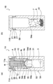
- FIG. 1 is a perspective view showing a sample storage device according to the first embodiment of the present invention.
- 2 (a) and 2 (b) are cross-sectional views showing a sample storage device according to the first embodiment of the present invention, and
- FIG. 2 (a) is an IIA-IIA of the first container shown in FIG.
- FIG. 2 (b) is a sectional view taken along line IIB-IIB of the second container shown in FIG.
- FIG. 3 is a cross-sectional view showing the cap complex removed from the first container.
- FIG. 4 is a cross-sectional view showing a state in which the cap portion of the first container according to the first embodiment is attached to the container body of the second container, and is a view corresponding to FIG. 2A.
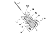
- FIG. 5 (a) to 5 (c) are views showing the cap complex removed from the first container
- FIG. 5 (a) is a perspective view
- FIG. 5 (b) is a cross section along the second direction Y
- FIG. 5 (c) is a cross-sectional view taken along the first direction X.
- FIG. 6 is a perspective view schematically showing how the liquid decomposition inhibitor is transferred from the agent holder to the medium holding the sample by using the cap complex according to the first embodiment.
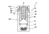
- FIG. 7 is a cross-sectional view showing a sample storage device according to a second embodiment of the present invention, and is a view corresponding to FIG. 2 (a).
- FIG. 8 is a cross-sectional view showing a sample storage device according to a third embodiment of the present invention, and is a view corresponding to FIG. 2 (a).
- FIG. 9 is a cross-sectional view showing a sample storage device according to a fourth embodiment of the present invention, and is a view corresponding to FIG. 2 (a).
- 10 (a) to 10 (c) show a state in which the liquid decomposition inhibitor is transferred from the agent holder to the medium holding the sample by using the sample storage tool according to the fourth embodiment of the present invention. It is a diagram schematically shown, FIG. 10 (a) is a perspective view, and FIGS. 10 (b) and 10 (c) are sectional views.
- FIG. 10 (a) is a perspective view
- FIGS. 10 (b) and 10 (c) are sectional views.
- FIG. 11 is a perspective view showing a sample storage device according to a fifth embodiment of the present invention, and is a view corresponding to FIG. 1.
- 12 (a) and 12 (b) are views schematically showing the first container shown in FIG. 11, and FIG. 12 (a) is a sectional view taken along line XIIa-XIIA of the first container shown in FIG. 12 (b) is a plan view of the cap portion of the first container shown in FIG. 11 as viewed from the back surface side.
- FIG. 13 is a side view showing the second container shown in FIG. 11 with a partially broken portion.
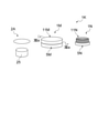
- 14 (a) and 14 (b) show how the liquid decomposition inhibitor is transferred from the agent holder to the medium holding the sample by using the sample storage device according to the fifth embodiment of the present invention.
- FIG. 14 (a) is an exploded perspective view
- FIG. 14 (b) is a sectional view
- 15 (a) and 15 (b) are diagrams showing a sample storage device according to a fifth embodiment of the present invention
- FIG. 15 (a) is an exploded view
- FIG. 15 (b) shows a sample storage state.
- FIG. 16 (a) and 16 (b) are views showing a sample storage device according to a sixth embodiment of the present invention
- FIG. 16 (a) is a view in which a container body and a cap portion are separated
- FIG. 16 ( b) is a cross-sectional view showing a sample storage state.
- the storage solution is used as it is in a liquid state.
- the medium from which the sample is collected is stored in the storage solution, for example, if the storage solution is an aqueous solution, the sample or the component to be inspected in the sample may be removed from the medium, or depending on the type of the component to be inspected in the sample. It may be unfavorable as a sample storage environment because it is easily decomposed by hydrolysis with water of the storage solution.
- the present invention relates to a sample storage tool that can solve the problems of the prior art.
- the sample storage tool 1 of the first embodiment includes a first container 1A and a second container 1B, and a medium in which the medium 2 holding the sample is housed in the first container 1A. It has a medium insertion unit 12 as a container, a liquid decomposition inhibitor 3 that suppresses decomposition of the sample to be inspected contained in the medium, and an agent holder 4 that can be impregnated with the decomposition inhibitor 3.
- the container 1B has a drying agent accommodating portion 6.
- FIG. 2 shows a state before the medium 2 holding the sample is housed in the medium insertion unit 12.
- the sample storage tool 1 stores the sample as a set containing the first container 1A and the second container 1B, more preferably a set containing the medium 2A capable of holding the sample in addition to the set of the first container 1A and the second container 1B. It is preferable to provide or distribute the ingredients to users.
- the user of the sample storage tool is a person who performs the work of accommodating the medium 2 holding the sample in the medium storage portion of the sample storage tool 1 so as to be stored in the sample storage tool 1, and is a doctor or a nurse. It is not limited to medical personnel such as researchers, and may be general consumers.
- the sample storage device of the present invention has the convenience of being safe to handle even by general consumers.
- the first container 1A and the second container 1B have an identification display 9 that makes it easy to distinguish between the two.
- the identification display 9 is provided by any method such as labeling and printing.
- the medium 2 holding the sample is housed in the medium insertion section (medium storage section) 12.
- the medium 2 holding the sample is a medium 2A capable of holding the sample, and the sample is held by an arbitrary method.
- the sample to be retained in the medium 2A is preferably a sample derived from an animal, and preferably contains a nucleic acid, a protein, a metabolite, or the like as a sample to be inspected.
- the animals referred to here include mammals including humans and non-human mammals, birds, reptiles, amphibians, fish, insects and the like. Examples of animal-derived specimens include skin surface lipids, saliva, blood, body fluids, and the like.
- the subject from which the sample is collected may be a living animal, a dead animal, or a non-living body to which a sample derived from the animal is attached, but it is possible to diagnose the health condition of various organisms. From the viewpoint of use for prediction and prediction, it is preferably a living body.
- Skin surface lipids are fat-soluble fractions present on the surface of the skin and are also called sebum.
- lipids on the surface of the skin are also referred to as "sebum".
- sebum mainly contains secretions secreted from exocrine glands such as sebaceous glands on the surface of the skin, and is present on the surface of the skin in the form of a thin layer covering the surface of the skin.
- the skin is a general term for regions including the epidermis, dermis, hair follicles, and tissues such as sweat glands, sebaceous glands, and other glands on the body surface, unless otherwise specified.
- the sebum contains nucleic acids derived from the cells of the subject from which the sebum is collected, particularly RNA (see Patent Document 1). Therefore, a typical example of the sample to be inspected when the sample is sebum is nucleic acid.
- RNA Ribonucleic acid
- the method for analyzing or analyzing the nucleic acid in the sample after storage is not particularly limited, and various known methods and the like can be used, and can be appropriately determined according to the purpose of analysis or analysis. Various known methods can also be used as a method for separating nucleic acid from a sample after storage with a sample storage tool.
- the sebum collected from the subject contains nucleic acids expressed in the skin cells of the subject, preferably containing nucleic acids expressed in any of the subject's epidermis, sebaceous glands, hair follicles, sweat glands, and dermis, more preferably. Contains nucleic acids expressed in any of the subject's dermis, sebaceous glands, hair follicles, and sweat glands.
- the nucleic acid derived from the subject's skin cells prepared from the specimen stored in the specimen storage device is preferably a nucleic acid derived from at least one site selected from the subject's epidermis, sebaceous gland, hair follicle, sweat gland and dermis.
- nucleic acid from at least one site selected from the epidermis, sebaceous glands, hair follicles and sweat glands is, for example, gene expression analysis and other genetic information analysis on the skin of the subject from which the sebum epidermal lipid is collected, functional analysis on the skin of the subject, and the subject's skin. It is useful as a sample for analysis of skin condition (for example, diagnosis of dermatitis), and analysis of the condition of a part other than the skin or the whole body of a subject (for example, diagnosis of various diseases).
- a method for analyzing or analyzing nucleic acid obtained from sebum for example, various methods described in Patent Document 1 can be used.
- the nucleic acid to be inspected may be either DNA or RNA, but RNA is preferable.
- RNA include mRNA, tRNA, rRNA, small RNA (for example, microRNA (miRNA), small interfering RNA (siRNA), Piwi-interacting RNA (piRNA), etc.), long intergenic non-coding (link) RNA, and the like.
- miRNA microRNA
- siRNA small interfering RNA
- piRNA Piwi-interacting RNA
- MiRNA is a small RNA having a length of about 19-30 nt among ncRNAs.
- LinkRNA is a long non-coding RNA having poly-A like mRNA, and has a length of 200 nt or more.
- the nucleic acid as a test component contained in the sample is preferably RNA having a length of 200 nt or more, and more preferably at least one selected from the group consisting of mRNA and lincRNA. Is.
- the first container 1A has a cap portion 11A and a container body 5A to which the cap portion 11A is mounted.
- the cap portion 11A is detachably attached to one end opening of the bottomed cylindrical container body 5A.
- the first container 1A has a medium insertion portion 12, a liquid decomposition inhibitor 3, and an agent holder 4.
- the agent holding body 4 is held by the cap portion 11A of the first container 1A, and even if the cap portion 11A is removed from the container body 5A, the state of being held by the cap portion 11A is maintained (see FIG. 3).
- the liquid decomposition inhibitor 3 is housed in the decomposition inhibitor storage section 31 provided in the container body 5A.
- the agent holding body 4 can be impregnated with the liquid decomposition inhibitor 3 and can maintain the impregnated state.
- the material for forming the agent holder 4 retains the liquid between the fibers (or in the pores) from the viewpoint of improving the retention of the liquid decomposition inhibitor 3 and the transferability of the liquid to the medium, but the material (fiber). ) Itself is preferably one that does not absorb liquid (moisture).
- the preferable forming material of the agent holding body 4 include a porous and flexible material, and examples thereof include felt, sponge, non-woven fabric and the like, or a laminate of one or more of these.
- the material for forming the agent holder 4 may be wool, wood pulp or the like in addition to the synthetic resin, but a material mainly composed of the synthetic resin is preferable in terms of containing no nucleic acid and drug resistance.
- the mass ratio of the synthetic resin is preferably 50% or more, preferably 90% or more, and more preferably 100% of the total mass.
- the medium 2 is inserted into the agent holder 4 as a medium accommodating portion for accommodating the medium 2 holding the sample.
- a medium insertion portion 12 for holding 2 is provided. It is preferable that the medium insertion unit 12 can hold the medium 2 simply by inserting the medium 2. More specifically, the medium insertion section 12 in the present embodiment will be described in more detail.
- FIG. 4s is provided, and when the medium 2 is inserted into the medium insertion portion 12, the medium 2 is stably held in the medium insertion portion 12 by receiving pressure from the pair of agent holding portions 4s and 4s. It has become like.
- the pair of agent holding portions 4s and 4s may be arranged in such a state that two independent agent holding bodies are arranged in close proximity or in contact with each other so that the medium insertion portion 12 is formed between them.
- one agent holding body 4 is provided with a slit-shaped notch, and the agent holding body 4 is the top surface portion 11a of the cap portion 11A.
- a non-divided portion 4r connecting the agent holding portions 4s and 4s is provided on the side.
- the facing surfaces 4a of the pair of agent holding portions 4s and 4s may or may not be in contact with each other in the state before the medium 2 is inserted into the medium inserting portion 12.
- the distance between the pair of phase-facing surfaces 4a should be appropriately determined in consideration of the thickness of the medium 2 when inserted into the medium insertion portion 12 and the transferability of the dispersion-suppressing liquid from the agent holder 4 to the medium 2.
- the shape of the medium 2A for holding the sample can be any shape such as a sheet shape, a block shape, a spherical shape with a handle, and the like, but as shown in FIG. 1, it is preferably a sheet shape.
- the sheet-shaped medium 2A preferably has flexibility and is preferably foldable.
- the sheet-shaped medium 2A has a smaller shape during storage than the area at the time of collection by folding the sample after holding it, or from the viewpoint of collection efficiency and workability when collecting the sample from the skin of an animal. It is preferable from the viewpoint of being able to do it. Further, when collecting a sample from the skin of a human or a non-human animal, using the sheet-shaped medium 2A has an advantage that the sheet can be deformed at the time of collection to reduce the irritation to the skin.
- a porous sheet can also be used as the sheet-shaped medium 2A. It is preferable to use a porous sheet because the sample is adsorbed on the micropores of the sheet and the sample can be held more firmly on the sheet.
- the sheet-shaped medium 2 after holding the sample can be stored in the medium insertion section 12 in a folded state a plurality of times, which makes it possible to reduce the size of the sample storage tool 1 and improve the transportability and handleability. It is preferable from the viewpoint of making it.
- the distance between the inner surfaces 4a of the agent holding portions 4s and 4s facing each other across the medium inserting portion 12 is such that the medium 2A can be easily inserted and the medium 2 can be separated from the fingers or instruments that were in contact with the medium 2A at the time of insertion. It can be appropriately set from the viewpoint of maintaining stability in the medium insertion portion 12, and is, for example, 0 mm or more and 10 mm or less, preferably 0 mm or more and 7 mm or less.
- the distance between the inner surfaces 4a of the pair of agent holding portions 4s and 4s is measured in the natural state before the medium 2 is inserted.
- a method capable of holding the sample can be used without particular limitation depending on the type of the sample.
- a method of collecting sebum as a sample a method of directly contacting the skin with a medium 2A capable of holding the sample, a method of collecting the sample by rubbing the sample collected using an instrument such as a spatula or a scraper against the medium 2A, or the like.
- the medium 2A capable of holding the sample is preferably one having a high adsorbability of the sample depending on the sample, and more preferably a sheet-shaped sample adsorbent is used.
- the sheet-shaped sample adsorbent when the sample is sebum
- a sheet-like material having sebum-adsorbing properties such as oil-blotting paper and oil-blotting film can be used.
- a sheet-like material containing a highly fat-soluble solvent in advance can also be used.
- the sheet-shaped medium 2A contains a highly water-soluble solvent or water, the adsorption of sebum is suppressed, so that the sheet-shaped medium 2A is preferably used in a dry state.
- the first container 1A of the present embodiment includes a pair of outer support portions 14 that cover the outer surface 4b side of the agent holder 4 on both sides of the medium insertion portion 12. More specifically, the first container 1A includes a support portion forming member 15 coupled to the cap portion 11A.
- the support portion forming member 15 is a member that supports the agent holding body 4 in a state of being held by the cap portion 11A, and a part thereof forms a pair of outer support portions 14.
- the cap portion 11A, the agent holding body 4, and the support portion forming member 15 form a cap portion complex 10 that can be integrally handled with the cap portion 11A when the cap portion 11A is removed from the container body 5A. ..
- the support portion forming member 15 has a base portion 16 located on the connection portion side with the cap portion 11A and a pair of outer support portions 14 branching and extending in two toward the tip end side in the direction protruding from the cap portion 11A. , 14 and are provided.
- the base portion 16 of the support portion forming member 15 is fixed to the cap portion 11A.
- the tubular connecting portion 16a formed in the lower part of the base portion 16 is fixed to the cap portion 11A by fitting with the tubular connecting portion 11b formed on the inner surface side of the top surface portion 11a of the cap portion 11A. Has been done.
- the first container 1A has a pair of outer support portions 14 sandwiched between fingers to increase or decrease the pressing force so that the medium 2 inserted into the medium insertion portion 12 can be inserted into the medium 2.
- the pressure for pressing the agent holder 4 can be increased or decreased.
- the entire support portion forming member 15 or the outer support portion 14 is provided with a relatively flexible synthetic resin such as polyethylene, polyester, polypropylene, polyamide-based synthetic resin, elastomer, rubber, or a composite material of two or more thereof.
- the pressure can be adjusted by configuring it with a material selected from.
- the pair of outer support portions 14 and 14 have a flexible portion 19 on the proximal end side thereof. It is preferable to have.
- the flexible portion 19 is a portion that serves as a base point for bending or bending of the outer support portion 14, and is preferably elastically deformable.
- the flexible portion 19 can be formed by partially forming the support portion forming member 15 into a thin wall or the like. Further, the flexible portion 19 can also be formed by providing a hinge structure in a part of the support portion forming member 15.
- FIG. 6 shows a state in which the pair of outer support portions 14, 14 are sandwiched between the thumb and the index finger.
- the pair of outer support portions 14, 14 are on the inner surface 14a, which is the surface on the medium insertion portion 12, and the side opposite to the medium insertion portion 12, respectively. It has an outer surface 14b located and a tip surface 14c located on the side opposite to the cap portion 11A side in the height direction Z of the cap portion composite 10.
- a holding recess 14d of the agent holding portion 4s is formed on the inner surface 14a side of each of the pair of outer supporting portions 14 and 14. Since a part of the agent holding portion 4s is housed in the holding recess 14d, the agent holding portion 4s is stably held at a predetermined position of the outer support portion 14.
- the agent holding portion 4s housed in the holding recess 14d is fixed in the holding recess 14d by any means such as adhesion by an adhesive, heat fusion, fitting, and engagement of engaging protrusions. May be good.
- the cross-sectional shape of the holding recess 14d and the agent holding portion 4s, which is orthogonal to the height direction Z of the cap portion composite 10, may be any shape such as a semicircle, a rectangle, or a triangle.
- the agent holding portions 4s and 4s shown in FIG. 5B each have a rectangular cross-sectional shape, and the facing inner surfaces 4a are substantially flat surfaces parallel to each other, but are limited thereto. Instead, for example, the opposing inner surfaces 4a of the agent holding portions 4s, 4s may be curved along one or both of the height direction Z and the first direction X of the cap portion complex 10.
- each of the pair of agent holding portions 4s a part of the outer surface side of the agent holding portion 4s is accommodated in the holding recess 14d, and the pair of agent holding portions 4s is the side accommodated in the holding recess 14d of the agent holding body.
- the opposite side protrudes from the holding recess 14d. That is, the surface of the agent holding portion 4s on the side opposite to the side housed in the holding recess 14d and the inner surface 14a of the outer support portion 14 that supports the agent holding portion 4s are not flush with each other, but the agent holding portion.
- the surface opposite to the side housed in the holding recess 14d in 4s is located closer to the medium insertion portion 12 than the inner surface 14a.
- the height direction Z of the cap portion composite 10 is such that the side where the support portion forming member 15 protrudes from the cap portion 11A is the upper side in the vertical direction and the cap portion.
- the direction is along the vertical direction.
- the direction in which the medium 2 is moved when the medium 2 is accommodated in the medium insertion portion 12 is substantially parallel to the direction in which the medium 2 is moved.
- the second direction Y of the cap portion complex 10 is a direction orthogonal to the height direction Z of the cap portion complex 10, and when the cap portion complex 10 is viewed in a plan view from one side of the height direction Z,
- the pair of outer support portions 14, 14 or the inner surfaces 4a of the agent holding portions 4s, 4s are opposed to each other, and the first direction X of the cap portion composite 10 is the height of the cap portion composite 10. It is a direction orthogonal to the direction Z, and is a direction orthogonal to the second direction Y when the cap portion complex 10 is viewed in a plan view from one side of the height direction Z.
- the support portion forming member 15 in the present embodiment has a liquid leakage prevention groove 17 on the inner surface 14a side of each of the pair of outer support portions 14, 14 as shown in FIG. 5 (c).
- the liquid leakage prevention groove 17 is formed on both sides of the outer support portion 14 so as to sandwich the holding recess 14d.
- the inner surface 14a of the outer support portion 14 is a flat surface on both sides of the holding recess 14d, and the liquid leakage prevention groove 17 is formed on the flat surface.
- the liquid leakage prevention groove 17 extends along the height direction Z of the cap portion composite 10. Further, the liquid leakage prevention groove 17 is terminated at a position that does not reach the upper ends of the opposite inner surfaces of the pair of outer support portions 14, 14.
- the support portion forming member 15 resupply the liquid that has passed through the liquid leakage prevention groove 17 to the agent holding portion 4s on the base end side of the cap portion composite 10 in the height direction Z.
- the lower end side of the liquid leakage prevention groove 17 is formed inside the tubular connection portion 11b via the through hole 17a formed in the base portion 16 of the support portion forming member 15, and the liquid resupply space 18 is formed. Communicate with.
- the undivided portion 4r of the pair of agent holding portions 4s and 4s is located in the liquid resupply space 18, and during the operation of transferring the liquid decomposition inhibitor 3 from the agent holding body 4 to the medium 2.
- the liquid that entered the liquid leakage prevention groove 17 without remaining in the state where the liquid decomposition inhibitor 3 discharged from the agent holding portion 4s adhered to the medium 2 is a liquid as shown by an arrow a in FIG. 5 (c).
- the leak prevention groove 17, the through hole 17a, and the undivided portion 4r flow through the liquid resupply path and are resupplied to the agent holding body 4.
- the cap portion complex 10 is inclined to guide the medium 2 to be inserted into the medium insertion portion 12 toward the insertion port 12a of the medium insertion portion 12 in the vicinity of the upper ends of the pair of outer support portions 14, 14 respectively. It has a guide surface 141.
- the support portion forming member 15 has a pair of inclined guide surfaces 141 on both sides of the central portion of the first direction X, and each of the pair of inclined guide surfaces 141 is in the height direction of the support portion forming member 15. It has a reverse-tapered shape in which the separation distance between the two decreases as the position of is lowered.
- a concave curved surface portion 142 having a shape along the convex curved surface portion of the inner plug 54, which will be described later, is provided.
- the inclined guide surface 141 is preferably located on the upper end side of the support portion forming member 15 with respect to the insertion port 12a.
- the sample storage tool 1 of the present embodiment has a storage portion 31 of a liquid decomposition inhibitor 3 inside the container body 5A of the first container 1A. Further, the first container 1A is provided with a partition portion 50 for partitioning the internal space of the liquid decomposition inhibitor 3 into a storage portion 31 and a storage portion 53 of the agent holder 4 and the outer support portion 14. A through hole 54d penetrating the partition portion 50 is formed in the partition portion 50. The through hole 54d functions as an agent supply hole for supplying the decomposition inhibitor 3 in the storage unit 31 to the agent holder 4 by the user of the sample storage tool 1 performing a predetermined operation.
- the predetermined operation in the present embodiment is that the cap portion 11A is placed on the upper side in the vertical direction and the bottom portion of the container body 5A is placed on the lower side in the vertical direction.
- an operation of shaking the first container 1A up and down can be mentioned.
- the first container 1A has the storage portion 31 of the decomposition inhibitor 3 and the agent holder 4 in a state of being separated internally, and the decomposition inhibitor 3 is operated until the storage portion 31 performs a predetermined operation.
- the fact that the agent holder 4 and the agent holder 4 can be maintained in a separated state can be stored in a more stable state, for example, the risk of volatilization and precipitation of the components of the decomposition inhibitor 3 can be reduced.
- the agent holding body 4 is provided in the cap portion 11A of the self-supporting container, and the liquid decomposition inhibitor storage portion may be provided in a portion vertically separated from the agent holding body 4.
- the partition portion 50 in the present embodiment is formed by arranging an inner plug 54 in the container main body 5A.
- the inner plug 54 is in contact with the cylindrical portion 54a having an outer peripheral surface shape that matches the inner peripheral surface shape of the container body 5A and the step portion 55 formed on the inner peripheral surface of the container body 5A, and the mounting position of the inner plug 54.
- the annular overhanging portion 54b has a dome-shaped tip-retracted portion 54c whose inner diameter and outer diameter gradually decrease toward one end opening side of the container body 5A, and the tip-retracted portion 54c.
- the through hole 54d is formed at the top.
- the partition portion 50 has a pair of the partition portions 50 having the facing surface side of the agent holding body 4 of the tip-squeezed shape portion 54c in the above-mentioned outer support portion 14. It is preferable that the shape is formed along the inclined guide surface 141 of the above. From the same viewpoint, it is preferable that the partition portion 50 and the inner plug 54 are formed so that the position of the through hole 54d faces the medium insertion portion 12 in the agent holder 4. Further, from the viewpoint of preventing the decomposition inhibitor 3 in the storage portion 31 from migrating to the agent holder 4 until the user intentionally performs a predetermined operation, the agent supply hole is formed in the inner plug 54.
- the opening area of the through hole 54d is preferably smaller than the opening area on the storage portion 31 side of the inner plug 54, and the opening area of the through hole 54d (agent supply hole) of the inner plug 54 is stored. It is preferably 10% or less, more preferably 5% or less of the opening area on the portion 31 side.
- the second container 1B in the first embodiment has a cap portion 11B and a container body 5B to which the cap portion 11B is mounted.
- the container body 5B of the second container 1B can be attached with the cap portion 11A removed from the container body 5A of the first container 1A.
- the container body 5B of the second container 1B before mounting the cap portion 11A of the first container 1A has a cap portion different from the cap portion 11A of the first container 1A. It is preferable to attach 11B and close the opening of the container body 5B.
- the cap portion 11B of the second container 1B in the present embodiment is detachably or detachably attached to one end opening of the container body 5B.
- the container body 5B in the second container 1B is not formed with the agent holding body 4, the support portion forming member 15, the inner plug 54, and the decomposition inhibitor storage portion 31 in the first container 1A, but instead is a desiccant.
- the cap portion 11A is removed from the container body 5A in the first container 1A, the medium 2 holding the sample is inserted into the medium insertion portion 12 attached to the cap portion 11A, and then the cap portion is inserted.
- a storage container 1C in which the cap portion 11A of the first container 1A and the container body 5B of the second container 1B are combined can be obtained. can.
- threads 21 and 58 are provided on the inner peripheral surface of the cap portion 11A and the outer peripheral surface of one end opening of the container body 5A, and the cap portion 11A is screwed into the container body 5A. Further, a sealing member such as packing (not shown) is arranged at the abutting portion between the cap portion 11A and the container body 5A and the abutting portion between the cap portion 11B and the container body 5B.
- the insides of the first container 1A, the second container 1B, and the storage container 1C can be hermetically sealed.
- the method of attaching the cap portions 11A and 11B to the container body 5A or the container body 5B is not limited to screwing, and any configuration such as engagement and fitting may be adopted.
- the desiccant accommodating portion 6 in the second container 1B is formed near the bottom of the container body 5B, and as shown in FIG. 4, the first container 1A to which the medium 2 holding the sample and the agent holder 4 are attached.
- the contact suppressing member 7 is located between the agent holding body 4 and the desiccant accommodating portion 6, and the desiccant 61 in the accommodating portion 6 is located. , It is designed so that it does not come into direct contact with the agent holder 4.
- the contact suppressing member 7 can isolate the desiccant 61 and the agent holding body 4 so as not to come into direct contact with each other, while being released from the agent holding body 4 or the decomposition suppressing agent transferred from the agent holding body 4 to the medium 2. Any form of any material can be used as long as it is capable of absorbing moisture and can achieve such purpose.
- the contact suppressing member 7 is a material that does not hinder the air permeability between the desiccant of the desiccant accommodating portion 6 and the agent holder 4. Examples of the contact suppressing member 7 include a porous member fixed at a predetermined height position in the internal space of the container body 5B, an inner plug, a cotton-like body made of synthetic resin, a sheet-like member having air permeability, and the like.
- the desiccant 61 one capable of absorbing the moisture and moisture released from the decomposition inhibitor can be used without particular limitation.
- a physical desiccant such as silica gel, aluminum oxide, molecular sieve, or zeolite, or a chemical desiccant such as fresh lime or calcium chloride can be used.
- the desiccant 61 may be used alone or in combination of two or more.
- the chemical desiccant is accompanied by a change in the substance when it is dried, while the physical desiccant does not change the substance and adsorbs water molecules on the porous surface. Therefore, the desiccant 61 can be used as a sample or a medium.
- a physical desiccant such as molecular sieve.
- a solution of the decomposition inhibitor 3 having a function of suppressing the decomposition of the component to be inspected that may be contained in the medium can be used without particular limitation.
- the sample contains an enzyme that decomposes the component to be inspected
- various liquid agents that can inhibit or inactivate the activity of the enzyme can be used.
- the sebum may contain a nucleic acid degrading enzyme derived from a subject or other germs. By inactivating such a nucleic acid degrading enzyme, the degradation of the nucleic acid contained in the sample can be suppressed.
- an aqueous solution containing guanidine hydrochloride, guanidine thiocyanate, urea, or thiourea which are chaotropic modifiers, can be used. Since it is not preferable for an aqueous solution containing guanidine hydrochloride or the like to come into contact with the body, when such a decomposition inhibitor is used, the use of the sample storage device 1 of the present invention is from the viewpoint of suppressing adhesion to the body. It is even more useful.
- the amount of the decomposition inhibitor 3 contained in the first container 1A can be appropriately determined according to the size of the medium 2 and the like. For example, FIG. 2A shows a state in which about 1 to 2 mL of the liquid decomposition inhibitor 3 is contained.
- the medium 2A holds a sample such as sebum by an appropriate method such as wiping the surface of the subject with a medium 2A capable of holding the sample.
- the medium 2A is folded a plurality of times to form a compact form.
- the agent holding body 4 is impregnated with the decomposition inhibitor 3 contained in the storage portion 31 in the first container 1A by a predetermined operation such as inverting the first container 1A and shaking it up and down a plurality of times.
- the cap portion 11A is removed from the container body 5A in the first container 1A, and the medium 2 holding the sample is inserted into the medium insertion portion 12 provided in the agent holder 4 attached to the cap portion 11A. Since the agent holding body 4 is impregnated with the liquid decomposition inhibitor 3, the liquid decomposition inhibitor 3 becomes efficient by inserting the medium 2 into the medium inserting portion 12 formed in the agent holding body 4. To move to medium 2. In a state where the medium 2 is inserted into the medium insertion portion 12, the outer support portions 14 and 14 are sandwiched between the fingers and the outer support portions 14 and 14 are pressed to decompose the liquid impregnated in the agent holder 4. The inhibitor 3 can be more effectively transferred to the medium 2 and the sample held in the medium 2. Further, by sandwiching the outer support portions 14 and 14 between the fingers and repeatedly increasing or decreasing the pressing force, the liquid decomposition inhibitor 3 impregnated in the agent holder 4 is transferred to the medium 2 more reliably and efficiently. Can be done.
- 11A is attached.
- the liquid decomposition inhibitor 3 is released from the agent holder 4. Since it can be transferred to the medium 2, decomposition of the test component in the sample contained in the medium 2 can be suppressed. Further, it is preferable to use the liquid decomposition inhibitor 3 from the viewpoint that the agent holder 4 can be efficiently impregnated and the impregnated decomposition inhibitor 3 can be efficiently transferred to the medium 2. Moreover, instead of bringing the liquid decomposition inhibitor 3 into direct contact with the medium 2 or the sample, the medium 2 comes into contact with the agent holder 4 impregnated with the liquid decomposition inhibitor 3 and the decomposition inhibitor comes into contact with the medium 2. Since 3 is arranged to migrate, it is possible to prevent the liquid decomposition inhibitor 3 from spilling or scattering to the surroundings during the work of bringing the decomposition inhibitor 3 into contact with the medium 2.
- the cap portion 11A after the medium 2 is inserted into the medium insertion portion 12 is mounted in the storage container 1C generated by attaching the cap portion 11A to the container body 5B of the second container 1B.
- the decomposition inhibitor 3 is used by the desiccant 61 without directly contacting the desiccant 61 with the agent holder 4. It can absorb the moisture released from. As a result, the amount of water in the liquid decomposition inhibitor remaining in the agent holder 4 can be reduced without directly contacting the desiccant 61 with the liquid decomposition inhibitor remaining in the agent holder 4, for example.
- the liquid decomposition inhibitor 3 is impregnated into the agent holder 4 and brought into contact with the medium 2 so that the liquid decomposition inhibitor 3 can be brought into contact with the body of the liquid decomposition inhibitor 3. Contact can be prevented, and by reducing the water content in the liquid decomposition inhibitor after storage in the medium, leakage of the liquid decomposition inhibitor and decomposition of the component to be inspected in the sample can be more effectively suppressed. Can be done. Further, according to the sample storage tool 1 of the first embodiment, no cooling facility is required, and the workability of storing and transporting the sample is excellent.
- the second container 1B has a contact suppressing member 7 which is arranged between the desiccant accommodating portion 6 and the agent holder 4 to prevent contact between the desiccant 61 and the agent holder 4, and has a desiccant.
- the fact that the 61 is not brought into direct contact with the agent holder 4 may occur depending on the combination of the liquid decomposition inhibitor 3 and the desiccant 61, such as heat generation caused by the direct contact between the aqueous solution of guanidine hydrochloride and the molecular sieve.
- heat generation caused by the direct contact between the aqueous solution of guanidine hydrochloride and the molecular sieve.
- the sample storage device of the second to seventh embodiments of the present invention will be described.
- the second to fifth embodiments will be described with reference to differences from the first embodiment, and the same reference numerals will be given and the description thereof will be omitted.
- the sample storage device of the second embodiment is different from the first embodiment in that it includes the first container 1A'shown in FIG. 7 instead of the first container 1A shown in FIG. 2 (a).
- the first container 1A'shown in FIG. 7 does not have an inner plug inside, and a liquid decomposition inhibitor is held in a state of being impregnated in the agent holder 4.
- the cap portion 11A is removed from the container body 5A'of the first container 1A'and the medium 2 holding the sample is inserted into the medium insertion portion 12 attached to the cap portion 11A.
- the cap portion 11A By attaching the cap portion 11A to one end opening of the container body 5B of the second container 1B as in the first embodiment, the cap portion 11A of the first container 1A'and the container of the second container 1B are attached. It can be a storage container combined with the main body 5B. According to the second embodiment, the same effect as that of the first embodiment is exhibited except for the effect of separating the decomposition inhibitor and the agent holder before use.
- the height of the first container 1A'in the second embodiment is different from that of the second container 1B, it is easier to distinguish between the first container 1A'and the second container 1B, and confusion is more reliably prevented. can.
- the height of the first container 1A'and the height of the second container 1B may be the same.
- the sample storage tool 1'of the third embodiment has a medium insertion unit 12 as a medium storage unit and a liquid that suppresses decomposition of the sample to be inspected contained in the medium in a single container 1D. It has a decomposition inhibitor 3 of the above, an agent holder 4 capable of impregnating the decomposition inhibitor 3, and a desiccant accommodating portion 6.
- the container 1D has a cap portion 11A for holding the agent holding body 4 and a container body 5D to which the cap portion 11A is detachably attached.
- the medium insertion portion 12 is provided in the agent holding body 4 held by the cap portion 11A.
- the agent holder 4 is impregnated with an appropriate amount of the decomposition inhibitor 3 in advance before the sample storage tool is used.
- a partition member 8 for preventing contact between the desiccant 61 in the accommodating portion 6 and the agent holding body 4 is arranged inside the container body 5D.
- the partition member 8 airtightly partitions between the agent holding body 4 and the desiccant accommodating portion 6, and the moisture in the decomposition inhibitor impregnated in the agent holding body 4 is removed by the desiccant 61 before use. It is designed not to be absorbed. As a result, the decomposition inhibitor is maintained in a liquid state, and the transfer of the decomposition inhibitor from the agent holder 4 to the medium 2 becomes good.
- the partition member 8 is, for example, an annular member provided with a thin film made of synthetic resin in the central portion.
- the cap portion 11A is removed from the container body 5D, and the medium insertion portion 12 of the agent holder 4 impregnated with the liquid decomposition inhibitor 3 in advance is used.
- the medium 2 is folded to an appropriate size and inserted, and if desired, the outer support portions 14 and 14 are pressed by hand to press the medium 2 from the agent holding body 4. Promotes the transfer of the decomposition inhibitor 3 to.
- a through hole is formed in the partition member 8 in the container body 5D from which the cap portion 11A is removed by using an appropriate puncture tool such as a toothpick or a dedicated puncture tool supplied as a set with the sample storage tool 1'.
- the partition member 8 having the through hole formed functions as a contact suppressing member.
- the cap portion 11A holding the medium 2 in the medium insertion portion 12 is attached to the container body 5D.
- the medium 2 is arranged in the medium insertion section (medium accommodating section) 12 under the state where the agent holder 4 is impregnated with the liquid decomposition inhibitor 3.
- the decomposition inhibitor 3 is transferred to the medium 2
- the desiccant 61 is transferred to the agent holder 4 while the medium 2 is housed in the medium insertion portion (medium accommodating portion) 12.
- the moisture released from the decomposition inhibitor 3 can be absorbed without direct contact. Therefore, according to the sample storage tool 1'of the third embodiment, the same effect as that of the sample storage tool of the first or second embodiment is exhibited. Further, since two containers, a first container and a second container, are not required, it is advantageous in terms of transportation, storage, handling and the like.
- the sample storage tool 1 "of the fourth embodiment includes a container 1E having a cap portion 11E and a container body 5E to which the cap portion is attached.
- the cap portion 11E is a bottomed cylinder. It is detachably attached to one end opening of the shaped container body 5E.
- the cap portion 11E is provided with a bottomed tubular desiccant accommodating body 60 having a desiccant accommodating portion 6 inside.
- the desiccant container 60 functions as a contact suppressing member that suppresses direct contact between the agent holder 4 impregnated with the liquid decomposition inhibitor and the desiccant 61.
- an agent holder 4 in a state of being impregnated with a liquid decomposition inhibitor is arranged inside the container body 5E.
- the agent holding body 4 has a portion arranged along the upper surface of the bottom portion of the container body 5E and the inner peripheral surface near the bottom portion. Then, as shown in FIG. 9, between the desiccant accommodating body 60 and the agent holding body 4 in a state where the cap portion 11E is attached to the container body 5E, the medium accommodating the medium 2 holding the sample is accommodated. It is part 12E.
- the desiccant container 60 is made of an agent-impermeable material that does not allow the decomposition inhibitor to permeate, and a ventilation hole 63 that communicates the inside and outside of the desiccant storage portion 6 is formed at a portion that does not come into contact with the medium 2.
- the ventilation hole 63 is closed with a seal or the like (not shown) in the state before inserting the medium, and after removing the cap portion 11E, the seal or the like can be removed before accommodating the medium 2 to allow ventilation. It is in a state of being.
- the ventilation hole 63 is formed in a portion of the desiccant container 60 on the cap portion 11E side.
- a plurality of ventilation holes 63 are formed around the desiccant container 60 so as to be spaced apart from each other in the circumferential direction. The number of ventilation holes 63 may be only one.
- the sample storage tool 1 "of the fourth embodiment As shown in FIG. 10A, after removing the cap portion 11E from the container body 5E and holding the sample in the sheet-shaped medium 2A'.
- the medium 2 folded to an appropriate size is positioned below the bottom 62 of the desiccant container 60 attached to the cap portion 11E, and as shown in FIG. 10 (b), the medium 2 is housed in the desiccant.
- the body 60 is pushed into the container body 5E, and as shown in FIG. 10 (c), the medium 2 is pressed against the agent holding body 4 by the desiccant container 60 to be brought into close contact with the container body 4, and the cap portion 11E is attached to the container body 5E.
- the space inside the container 1E is sealed.
- the medium 2 can be arranged in the medium storage unit 12E under the state where the agent holder 4 is impregnated with the liquid decomposition inhibitor 3, thereby.
- the decomposition inhibitor 3 is transferred to the medium 2.
- the desiccant 61 allows the moisture released from the decomposition inhibitor 3 to pass through the container 1E whose inside is closed. It is absorbed through the pores 63 without directly contacting the agent holder 4.
- the sample storage device 1 of the fourth embodiment the sample storage device of the first to third embodiments is used. A similar effect is achieved.
- the sheet-shaped medium 2 is wrapped around the lower part of the desiccant container 60.
- the medium 2 may be pushed into the space surrounded by the agent holding body 4 in the container body 5E and brought into close contact with the agent holding body 4.
- FIG. 11 is a diagram showing a sample storage device 1K according to a fifth embodiment of the present invention.
- the sample storage tool 1K of the fifth embodiment includes a first container 1M having a cap portion 11M and a container body 5M to which the cap portion 11M is mounted, and an inner container 5N housed in the first container 1M. There is.
- the inner container 5N is combined with the cap portion 11N to form the second container 1N.
- the sample storage tool 1K of the fifth embodiment is preferably provided to the user as a set of the first container 1M and the second container 1N.
- the sample storage tool 1K of the fifth embodiment has an agent holder 4 capable of containing a liquid decomposition inhibitor in the first container 1M, and a part of the inner container 5N is a desiccant accommodating portion 6. It is a desiccant container 60 having the above.
- the cap portion 11M is removed from the container body 5M in the first container 1M, and the container body 5M is housed in a holding body.
- the medium 2 holding the sample is placed on the agent holder 4 housed in the part 51, and the inner container 5N containing the desiccant 61 is placed in the container container 52 of the container body 5M, and then the second container is placed.
- a storage container 1G in which the inner container 5N is housed in the first container 1M can be obtained.
- the first container 1M has a cap portion 11M and a container body 5M on which the cap portion 11M is mounted.
- the cap portion 11M is detachably attached to one end opening of the bottomed cylindrical container body 5M.
- the cap portion 11M has a sealing member 41 on the back surface 30b side of the top surface portion 31m.
- the seal member 41 has a plan view shape along the peripheral shape of the opening of the inner container 5N, and has a substantially circular annular shape.
- the seal member 41 is arranged on the peripheral edge of the top surface portion 31 m of the cap portion 11M.
- Examples of the sealing member 41 include packings made of materials such as rubber, silicon, elastomer, polyethylene, foamed polyethylene, polypropylene, and foamed polypropylene.
- the cap portion 11M has a ridge portion 33 protruding from the back surface 31b of the top surface portion 31m.
- the ridge 33 extends along one direction.
- the ridge portion 33 is arranged in the region surrounded by the seal member 41.
- the end portion 33a in the longitudinal direction of the ridge portion 33 does not reach the seal member 41.
- a gap is formed between the longitudinal end 33a of the ridge 33 and the seal member 41.
- the cap portion 11M may have only one ridge portion 33, or may have a plurality of ridge portions 33.
- the directions in which the plurality of convex portions 33 extend may intersect each other, or are substantially parallel to each other as shown in FIG. 12 (b). May be good.
- the container body 5M has a holding body accommodating portion 51 capable of accommodating the agent holding body 4 and a container accommodating portion 52 capable of accommodating the inner container 5N.
- the container accommodating portion 52 is located closer to the opening side of the container body 5M than the holding body accommodating portion 51.
- the holding body accommodating portion 51 is a space surrounded by a first peripheral wall portion 51b erected from the bottom portion 51a and the peripheral portion of the bottom portion 51a of the container body 5M.
- the container accommodating portion 52 is a space surrounded by a second peripheral wall portion 52b located on the opening side of the container main body 5M with respect to the first peripheral wall portion 51b.
- the second peripheral wall portion 52b has a larger diameter than the first peripheral wall portion 51b.
- the lower end of the second peripheral wall portion 52b and the upper end portion of the first peripheral wall portion 51b are connected by a connecting portion 56.
- the second container 1N has a cap portion 11N and an inner container 5N to which the cap portion 11N is mounted.
- the cap portion 11N is detachably attached to the opening of the bottomed cylindrical inner container 5N.
- the inner container 5N is adapted to be accommodated in the container accommodating portion 52 of the container body 5M of the first container 1M (see FIGS. 14 (a) and 14 (b)). Further, as shown in FIG. 13, the inner container 5N has a desiccant container 60 having a desiccant container 6 inside.
- the desiccant container 60 is a contact suppressing member that suppresses direct contact between the agent holding body 4 impregnated with the liquid decomposition inhibitor and the desiccant 61 when placed in the container body 5M of the first container 1M. Functions as.
- the inner container 5N has a container peripheral wall portion 71 in addition to the desiccant container 60. The container peripheral wall portion 71 is located outside the inner container 5N in the radial direction with respect to the desiccant container 60.
- the cap portion 11N has a top surface portion 31n and a peripheral wall portion 32n extending from the peripheral portion of the top surface portion 31n.
- the peripheral wall portion 32n extends from the peripheral edge portion of the top surface portion 31n toward both sides of the cap portion 11N in the height direction H.
- the peripheral wall portion 32n includes an upper peripheral wall portion 32u located above the top surface portion 31n in the height direction H and a lower peripheral wall portion 32d located below the top surface portion 31n in the height direction H. including.
- the length of the peripheral wall portion 32n in the height direction H is used. It can be long enough for a person to grip the peripheral wall portion 32n.
- the peripheral wall portion 32n can be gripped and the cap portion 11N can be rotated with respect to the inner container 5N. It will be easier. From the viewpoint of making it easier for the user to grip the peripheral wall portion 32n, it is preferable that the peripheral wall portion 32 has a rib 31r on its outer surface as shown in FIGS. 11 and 13.
- the inner container 5N is housed in the container body 5M and the cap portion 11M is attached to the container body 5M.
- the medium accommodating portion 12 is formed between the desiccant accommodating body 60 and the agent holding body 4.
- the medium storage unit in the sample storage device of the present invention is not limited to the one formed from the beginning like the medium insertion unit 12 of the first embodiment, and a plurality of members constituting the sample storage device 1K may be combined. For example, those formed by combining the first container 1M and the inner container 5N in the present embodiment are also included.
- the cap portion 11M is removed from the container body 5M in the first container 1M, and the desiccant container 60 and the agent holding are held. After the medium 2 is arranged between the body 4 and the body 4, the medium 2 is brought into close contact with the agent holding body 4 by attaching the cap portion 11M to the container body 5M.
- the medium 2A holds a sample such as sebum by an appropriate method such as wiping the surface of the subject with a medium 2A capable of holding the sample. It is also preferable to use an auxiliary tool 25 capable of detachably holding the medium 2A when performing an operation such as wiping the surface of the subject with the medium 2A.
- the auxiliary tool 25 By using the auxiliary tool 25, the user can perform an operation such as grasping the auxiliary tool 25 and wiping the surface of the subject without directly grasping the medium 2A. Therefore, the medium 2A is other than the sample. It is possible to prevent things from adhering.
- the auxiliary tool 25 preferably has a cushioning property. Further, it is preferable that the auxiliary tool 25 can adhere the medium 2A without using an adhesive.
- various synthetic resin foams having cushioning properties can be used, and preferably, a material having a suction cup structure or the like having a large number of recesses on the surface where the inside is depressurized by pressure contact is used.
- a material bonded to a material having cushioning properties can be used. Examples of the material having cushioning properties include foams of elastic resin, and specifically, ethylene / propylene / diene copolymer (EPDM), NBR, PE, PP, PET, SBR, elastomer, silicon rubber and the like.
- EPDM ethylene / propylene / diene copolymer
- Examples thereof include a foam containing the above as a raw material.
- the material having cushioning property shall be a constituent material to be used by selecting a synthetic resin having an elastic restoring force against compression, a sponge made of a natural material, a non-woven fabric, a woven fabric, or a composite material of two or more of these. Is preferable.
- Examples of the material having a suction cup structure include an acrylic resin and the like.
- the shape of the auxiliary tool 25 capable of holding the medium 2A is not particularly limited, and examples thereof include a rectangular parallelepiped, a columnar body, and a hemispherical body.
- the columnar body or the like may have a flat shape as shown in FIG.
- the cross-sectional shape of the rectangular parallelepiped or the columnar body is not particularly limited, and may be a circular shape (see FIG. 11), an elliptical shape, a rectangular shape, a rhombus shape, or the like.
- the cap portion 11M is removed from the container body 5M in the first container 1M, and the medium 2 holding the sample is placed on the agent holding body 4 impregnated with the decomposition inhibitor 3 (FIGS. 14A and 14B). )reference).
- the medium 2 is held by the auxiliary tool 25, the medium 2 is removed from the auxiliary tool 25 and the medium 2 is placed on the agent holding body 4.
- the inner container 5N of the second container 1N containing the desiccant 61 from which the cap portion 11N has been removed is placed in the container storage portion 52 of the container body 5M of the first container 1M (FIG. 14 (a). ) And (b)).
- the inner container 5N in the container accommodating portion 52, the medium 2 is arranged between the accommodating portion 6 of the desiccant 61 and the agent holding body 4.
- the medium 2 comes into close contact with the agent holding body 4. More specifically, when the cap portion 11M is attached to the container body 5M, the top surface portion 31m of the cap portion 11M abuts on the upper end portion 60a of the desiccant accommodating body 60 of the inner container 5N, and the inner container 5N is pushed down. When the inner container 5N is pushed down, the medium 2 is pressed against the agent holding body 4 by the bottom of the desiccant container 60, and the medium 2 comes into close contact with the agent holding body 4.
- the cap portion 11M is attached to the container body 5M from the viewpoint of ensuring that the medium 2 is in close contact with the agent holder 4 when the cap portion 11M of the first container 1M is attached to the container body 5M.
- the distance L1 (see FIG. 12 (a)) from the back surface of the top surface portion 31 m to the top surface of the bottom portion of the container body 5M in the state of being mounted on the inner container 5N is the height L2 of the inner container 5N (see FIG. 13) and an external force is applied. It is smaller than the total value with the thickness L3 (see FIG. 12 (a)) of the agent holder 4 in the untreated state.
- the sealing member 41 of the cap portion 11M abuts on the upper end portion of the container main body 5M, and the space inside the container main body 5M is sealed.
- the storage part 6 of the desiccant 61 and the storage part 4 of the agent holder 4 are attached.
- a communication passage that communicates with 51 is formed. This point will be described in detail below.
- a gap is formed between the upper end portion 60a of the desiccant container 60 and the top surface portion 31m of the cap portion 11M. More specifically, in the storage container 1G, as shown in FIG.
- the convex portion 33 of the top surface portion 31m of the cap portion 11M abuts on the upper end portion 60a of the desiccant container 60, and the top surface portion 31m.
- a gap is formed between the portion other than the ridge portion 33 on the back surface of the desiccant container 60 and the upper end portion 60a of the desiccant container 60.
- This gap constitutes a part of a communication passage that communicates the accommodating portion 6 of the desiccant 61 and the accommodating portion 51 of the agent holding body 4.
- a gap is formed between the lower end portion 71b of the container peripheral wall portion 71 of the inner container 5N and the connection portion 56 of the container body 5M. This gap also constitutes a part of the communication passage that communicates the accommodating portion 6 of the desiccant 61 and the accommodating portion of the agent holding body 4.
- the accommodating portion 6 of the desiccant 61 and the accommodating portion 51 of the agent holding body 4 are the upper end portion 60a of the desiccant accommodating body 60 and the top surface portion of the cap portion 11M. It communicates through a gap between 31 m and a gap between the lower end portion 71b of the container peripheral wall portion 71 of the inner container 5N and the connection portion 56 of the container body 5M. Therefore, in the storage container 1G whose inside is closed, the moisture released from the decomposition inhibitor 3 is absorbed by the desiccant 61 without directly contacting the agent holder 4 through these gaps. In this way, according to the sample storage tool 1K of the fifth embodiment, the same effect as that of the sample storage tool of the first to fourth embodiments is obtained.
- a method for providing the sample storage tool 1K of the fifth embodiment to a user or the like will be described with reference to a preferred example.
- the agent holder 4 and the desiccant 61 are housed in the first container 1M and the second container 1N, respectively.
- the cap portion 11M is attached to one end opening of the container body 5M to form an agent.
- the first container 1M in which the holding body 4 is housed is formed.
- the cap portion 11N is attached to the opening of the inner container 5N to form a second container 1N in which the desiccant 61 is housed. Then, by sending the first container 1M and the second container 1N thus formed in a packing container together with the medium 2A capable of holding the sample to the user or the like, the sample storage tool 1K can be obtained. offer.
- the sample storage tool 1K of the fifth embodiment does not have to have the cap portion 11N of the second container 1N, but is a pre-use sealing member that closes the opening of the storage portion 6 of the desiccant 61 of the inner container 5N. It is preferable to provide.
- the pre-use sealing member is the cap portion 11N of the second container 1N.
- the inner container 5N has a state in which the opening of the accommodating portion 6 of the desiccant 61 is closed by the pre-use sealing member, in other words, the cap portion 11N is the inner container 5N. It is preferable that the product is provided to the user in a state of being attached to the user.
- the pre-use sealing member By providing the inner container 5 with the opening of the desiccant 61 accommodating portion 6 closed by the pre-use sealing member, foreign matter other than the desiccant 61 may be mixed or dried in the desiccant 61 accommodating portion 6. It is possible to prevent the agent 61 from coming out of the accommodating portion 6 of the desiccant 61.
- a shielding film such as Parafilm (trademark) can also be used.
- the sample storage tool 1P of the sixth embodiment includes a container 1F having a cap portion 11F and a container body 5F to which the cap portion 11F is detachably attached. In the state of being provided to the user of the sample storage tool, only the agent holder 4 impregnated with the liquid decomposition inhibitor 3 is arranged inside the container 1F. Further, the sample storage tool 1P of the sixth embodiment has a sheet-shaped medium 2, a disk-shaped contact suppressing member 7, and a desiccant 61 that are housed and provided in a bag container or the like separate from the container 1F. There is.
- the contact suppressing member 7 can separate the desiccant 61 and the agent holding body 4 so as not to come into direct contact with each other, while the agent holding body 4 or the agent holding body 4 can be separated from each other. It is possible to allow the moisture released from the decomposition inhibitor transferred from the 4 to the medium 2 to pass through and to be absorbed by the desiccant 61.
- the cap portion 11F is removed from the container body 5F, and the liquid decomposition inhibitor, which is arranged in the container body 5F, is impregnated in advance, and the predetermined meat is used.
- the thick disk-shaped agent holder 4 is exposed.
- the agent holding body 4 is made of a member such as a sponge having an elastic recovery force against compression.
- the medium 2 after the sample is held by the sheet-shaped medium 2A'is placed on the agent holding body 4.
- the medium 2 may be placed on the agent holding body 4 as it is in the unfolded state, or may be placed on the agent holding body 4 in a compact state by folding it once or a plurality of times.
- the contact suppressing member 7 and the desiccant 61 are sequentially placed on the medium 2, and then the cap portion 11F is attached to the container body 5F.
- the medium 2 is arranged in the medium storage portion 12F located on the agent holder 4 under the state where the agent holder 4 is impregnated with the liquid decomposition inhibitor 3. This allows the degradation inhibitor 3 to migrate to the medium 2.
- the medium 2 arranged in the medium accommodating portion 12F is preferably brought into close contact with the agent holding body 4 by the contact suppressing member 7 or other members, and more preferably pressed against the agent holding body 4.
- an arbitrary method such as increasing the total thickness of the members arranged between the container body 5F and the cap portion 11F is adopted as compared with the thickness between the container body 5F and the cap portion 11F. can. Further, as shown in FIG.
- the desiccant 61 transfers the moisture released from the decomposition inhibitor 3 to the agent holder 4 via the contact inhibitor 7. Absorb without direct contact. In this way, according to the sample storage tool 1P of the sixth embodiment, the same effect as that of the sample storage tool of the first to fifth embodiments is obtained.
- the sample storage tool 1P'of the seventh embodiment is shown in FIGS. 16 (a) and 16 (b).
- the agent holding body 4 impregnated with the liquid decomposition inhibitor 3 is provided on the container body 5F side of the cap portion 11F and the container body 5F in the container 1F before use.
- liquid decomposition occurs on the cap portion 11F side of the container 1F before use. The difference is that the agent holder 4 impregnated with the inhibitor 3 is fixed.
- the contact suppressing member 7 is fitted and fixed to the opening of the container body 5F in the container 1F before use, and the container body 5F and the contact suppressing member 7 are fixed to each other.
- a desiccant accommodating portion 6 is formed between them.
- the medium accommodating portion 12F is between the contact suppressing member 7 and the agent holding body 4.
- the contact suppressing member 7 is made of, for example, a synthetic resin, and has a plurality of ventilation holes formed therein.
- a cotton-shaped, sheet-shaped, plate-shaped or the like can be used as the contact suppressing member 7, a cotton-shaped, sheet-shaped, plate-shaped or the like. It is preferable that the ventilation holes of the contact suppressing member 7 are closed by a sealing material or the like before the medium 2 is arranged. According to the sample storage tool 1P'of the 7th embodiment, the same effect as that of the sample storage tool of the 1st to 5th or 6th embodiments is exhibited.
- the single container 1E includes the desiccant container 60 and the agent holder 4 impregnated with the liquid decomposition inhibitor.
- a first container provided with a cap portion provided with a desiccant container 60 and a second container in which a drug holder 4 in a state in which a liquid decomposition inhibitor is impregnated are arranged inside the container body.
- the sample storage tool 1K of the fifth embodiment may separately provide the first container 1M and the second container 1N and the medium 2A capable of holding the sample, or the first container 1M and the second container. 1N and medium 2A may be provided separately. Further, the sample storage tool 1K may be provided to the user or the like without accommodating the agent holder 4 and the desiccant 61 in the first container 1M and the second container 1N, respectively. More specifically, the first container 1M and the second container 1N, the agent holder 4, the desiccant 61, and the medium 2A, which do not contain anything inside, are individually packaged and put into a packaging container. It may be packed and sent to the user or the like.
- the form in which the decomposition inhibitor is held in the agent holder in advance has been described, but also in these forms, the liquid decomposition inhibitor is contained in the container containing the agent holder. It can also be placed in another container such as a bag or tube and applied to the agent holder immediately before use.
- a cap portion that can be attached to the container body 5B of the second container 1B is formed by integral molding or the like on the outside of the bottom of the container bodies 5A, 5A'of the first container 1A, 1A'in the first or second embodiment.
- the cap portion may be used as the cap portion 11B for closing the opening of the second container 1B before use.
- the opening of the container body of the second container 1B may be closed with a shielding film such as Parafilm (trademark).
- the agent holder is impregnated with the liquid decomposition inhibitor to bring it into contact with the sample, thereby preventing the liquid decomposition inhibitor from coming into contact with the body and decomposing the sample into a liquid.
Abstract
Description
また本出願人は、皮膚表上脂質にその個体に由来するRNAが存在することを知見し、該知見に基づき、被検体から採取された皮膚表上脂質から核酸を分離することを含む、被検体の皮膚細胞に由来する核酸の調製方法を報告している(特許文献1)。
保存溶液が身体に触れないように検体を採取する技術としては、唾液を検体とする技術として、唾液をロート状の採取部に採取した後、蓋を閉めることによって、蓋に設けられた貫通部材が、採取部と保存溶液との間の仕切り膜を貫通して、唾液と保存溶液とが混合されるようにした容器システムが提案されている(特許文献2)。
検体を採取した媒体を保存溶液中に保存する場合、例えば、保存溶液が水溶液であると、媒体から検体または検体中の被検査成分が外れてしまったり、また検体の被検査成分の種類によっては保存溶液の水分による加水分解等によって分解し易くなる等、検体の保存環境として好ましくない場合がある。
図1及び図2は、本発明の第1実施形態に係る検体保存具1を示す図である。
第1実施形態の検体保存具1は、図2に示すように、第1容器1Aと第2容器1Bとを含んでおり、第1容器1Aに、検体を保持した媒体2が収容される媒体収容部としての媒体挿入部12と、該媒体に含まれる被検査試料の分解を抑制する液状の分解抑制剤3と、分解抑制剤3を含浸可能な剤保持体4とを有し、第2容器1Bに、乾燥剤の収容部6を有している。
動物由来の検体としては、例えば、皮膚表上脂質(skin surface lipids)、唾液、血液、体液等が挙げられる。検体が採取される被験体は、生存している動物の生体、死亡している動物、動物由来の検体が付着している非生物のいずれであってもよいが、各種生物の健康状態の診断や予測に用いる観点からは、生体であることが好ましい。
本出願人は、皮脂中に該皮脂が採取される被検体の細胞に由来する核酸、特にRNAが含まれることを報告している(特許文献1参照)。したがって、検体が皮脂である場合の被検査試料の代表例は核酸である。皮脂を検体とし、該皮脂を、核酸が分解されないように本発明の検体保存具にて保存することは、生存する被験体から簡便かつ低侵襲にて核酸を含む検体を採取することができる点、及び皮脂に含まれる核酸が比較的微量であっても、その分解を抑制して各種の分析又は解析を効果的に行うことができる点から好ましい。
保存後の検体中の核酸の分析又は解析方法は、特に制限されず、各種公知の方法等を用いることができ、また分析又は解析の目的に応じて適宜に決定することができる。検体保存具にて保存後の検体から核酸を分離する方法も各種公知の方法を用いることができる。
被験体から採取された皮脂中に由来する核酸は、例えば、皮脂表皮脂質を採取される被験体の皮膚に関する遺伝子発現解析およびその他の遺伝子情報の解析、被験体の皮膚に関する機能解析、被験体の皮膚状態の解析(例えば、皮膚炎の診断)、さらには被験体の皮膚以外の部位または全身の状態の解析(例えば、各種疾患の診断)などのための試料として有用である。皮脂から得られる核酸の分析又は解析方法は、例えば特許文献1に記載の各種の方法を用いることができる。
第1容器1Aは、図1及び図2(a)に示すように、キャップ部11A及びキャップ部11Aが装着される容器本体5Aを有している。キャップ部11Aは、有底筒状の容器本体5Aの一端開口部に脱着自在に装着されている。
第1容器1Aは、媒体挿入部12、液状の分解抑制剤3及び剤保持体4を有している。剤保持体4は、第1容器1Aのキャップ部11Aに保持されており、キャップ部11Aを容器本体5Aから取り外しても、キャップ部11Aに保持された状態が維持される(図3参照)。液状の分解抑制剤3は、容器本体5A内に設けられた分解抑制剤の貯留部31に収容されている。
剤保持体4の形成素材は、合成樹脂の他、羊毛、木材パルプ等であっても良いが、核酸を含まない点や薬剤耐性等の点で、合成樹脂を主体とするものが好ましい。合成樹脂を主体とする形成材料は、合成樹脂の質量割合が総質量の50%以上が好ましく、好ましくは90%以上、より好ましくは100%である。
検体を保持させる媒体2Aの形状は、シート状、ブロック状、持ち手のついた球状等、任意の形状とすることができるが、図1に示すように、シート状であることが好ましい。シート状の媒体2Aは、可撓性を有することが好ましく、また折り畳み可能であることが好ましい。
シート状の媒体2Aは、動物の皮膚から検体を採取する場合の採取効率や作業性の観点、又は検体を保持させた後に折り畳むことで、採取時の面積に比して保存時の形態を小さくできる等の観点から好ましい。また、ヒトや非ヒト動物の肌から検体を採取する場合、シート状の媒体2Aを用いることは、採取時にシートが変形して肌への刺激を小さくすることができる利点もある。シート状の媒体2Aとしては、多孔質のシートを用いることもできる。多孔性のシートを用いると、検体がシートの微細孔に吸着され、検体をシートに、よりしっかりと保持できるので好ましい。
より具体的に説明すると、第1容器1Aは、キャップ部11Aに結合した支持部形成部材15を備えている。支持部形成部材15は、剤保持体4を、キャップ部11Aに保持された状態に支持する部材であり、その一部が、一対の外側支持部14を形成している。キャップ部11A、剤保持体4及び支持部形成部材15は、キャップ部11Aを容器本体5Aから取り外したときに、キャップ部11Aと一体的に取り扱うことができるキャップ部複合体10を形成している。
支持部形成部材15は、キャップ部11Aとの接続部側に位置する基部16と、キャップ部11Aから突出する方向の先端側に向かって2つに分岐して延在する一対の外側支持部14,14とを備えている。支持部形成部材15の基部16は、キャップ部11Aに固定されている。具体的には、基部16の下部に形成された筒状接続部16aが、キャップ部11Aの天面部11aの内面側に形成された筒状接続部11bと嵌合することによってキャップ部11Aに固定されている。
一対の外側支持部14,14それぞれの内面14a側には、図5(c)に示すように、剤保持部4sの保持用凹部14dが形成されている。剤保持部4sの一部が保持用凹部14d内に収容されていることで、剤保持部4sが外側支持部14の所定位置に安定に保持される。保持用凹部14d内に収容された剤保持部4sは、保持用凹部14d内に、接着剤による接着、熱融着、嵌合、係合突起の係合等の任意の手段により固定されていてもよい。保持用凹部14d及び剤保持部4sの、キャップ部複合体10の高さ方向Zと直交する横断面形状は、半円形、矩形、三角形等の任意の形状とすることができる。図5(b)に示す剤保持部4s,4sは、いずれも横断面形状が矩形状であり、相対向する内面4aが互いに平行な略平坦な面となっているが、それに制限されるものではなく、例えば、剤保持部4s,4sの相対向する内面4aが、キャップ部複合体10の高さ方向Z又は第1方向Xのうちの一方又は両方に沿って湾曲していてもよい。
このように、第1容器1Aが、分解抑制剤3の貯留部31と剤保持体4とを内部に分離した状態に有し、貯留部31が、所定の操作をするまで、分解抑制剤3と剤保持体4とを分離した状態に維持可能であることは、例えば分解抑制剤3の成分の揮発や析出のリスクを減らすことができる等、分解抑制剤3をより安定な状態で保存できる点から好ましい。
分解抑制剤3と剤保持体4とを分離した状態に維持可能とする構成としては、本実施形態のように、分解抑制剤3と剤保持体4との間に仕切り部50を設ける方法が好ましいが、自立可能な容器におけるキャップ部11Aに剤保持体4を設け、剤保持体4とは鉛直方向に離間した部位に液状の分解抑制剤の貯留部を設けるだけでもよい。
貯留部31から剤保持部4sへの分解抑制剤3の移行の観点から、仕切り部50は、先すぼまり形状部54cの剤保持体4の臨む面側が、前述の外側支持部14における一対の傾斜ガイド面141に沿う形状に形成されていることが好ましい。また、同観点から、仕切り部50及び中栓54は、貫通孔54dの位置が、剤保持体4における媒体挿入部12と対向する位置に形成されていることが好ましい。また使用者が、意図的に所定の操作をするまで、貯留部31内の分解抑制剤3を剤保持体4に移行しないようにする観点から、中栓54に形成された剤供給孔としての貫通孔54dは、その開口面積が、中栓54における、貯留部31側の開口面積に比して小さいことが好ましく、中栓54は、貫通孔54d(剤供給孔)の開口面積が、貯留部31側の開口面積の10%以下であることが好ましく、より好ましくは5%以下である。
第2容器1Bの容器本体5Bは、図4に示すように、第1容器1Aの容器本体5Aから取り外したキャップ部11Aを装着可能である。本実施形態における第2容器1Bのように、第1容器1Aのキャップ部11Aを装着する前の第2容器1Bの容器本体5Bには、第1容器1Aのキャップ部11Aとは別のキャップ部11Bを装着して、容器本体5Bの開口部を閉鎖しておくことが好ましい。本実施形態における第2容器1Bのキャップ部11Bは、容器本体5Bの一端開口部に取り外し可能又は脱着自在に装着されている。
接触抑制部材7は、乾燥剤61と剤保持体4とを、直接接触しないように隔離することができる一方、剤保持体4又は剤保持体4から媒体2に移行した分解抑制剤から放出される湿気を吸収可能なものであり、斯かる目的を達成し得るかぎり、任意の素材からなる任意の形態のものを用いることができる。接触抑制部材7は、乾燥剤の収容部6の乾燥剤と剤保持体4との間の通気性は阻害しない材料である。接触抑制部材7としては、容器本体5Bの内部空間の所定の高さ位置に固定された多孔性部材、中栓、合成樹脂からなるワタ状体、通気性を有するシート状部材等が挙げられる。
乾燥剤61を用いることで、水分の存在下に反応が促進される加水分解による被検査成分の分解を、一層効果的に抑制することができる。
まず、検体を保持可能な媒体2Aにより、被験体の表面を拭き取る等の適宜の方法により、該媒体2Aに、皮脂等の検体を保持させる。シート状の媒体2Aである場合、該媒体2Aを複数回折り畳んでコンパクトな形態とする。
そして、第1容器1Aを倒立させて複数回上下に振る等の所定の操作によって、第1容器1A内の貯留部31に収容されている分解抑制剤3を剤保持体4に含浸させた後、第1容器1Aにおける容器本体5Aからキャップ部11Aを取り外し、該キャップ部11Aに付随する剤保持体4に設けられた媒体挿入部12に、検体を保持した媒体2を挿入する。
剤保持体4には、液状の分解抑制剤3が含浸されているため、剤保持体4に形成された媒体挿入部12に媒体2を挿入することによって、その液状の分解抑制剤3が効率的に媒体2へと移行する。
媒体挿入部12に媒体2が挿入された状態において、外側支持部14,14を手指間に挟んで、外側支持部14,14を加圧することにより、剤保持体4に含浸された液状の分解抑制剤3を、一層効果的に、媒体2及び媒体2に保持された検体に移行させることができる。更に外側支持部14,14を手指間に挟んで押圧力を繰り返し増減させることにより、一層確実且つ効率的に、剤保持体4に含浸された液状の分解抑制剤3を媒体2に移行させることができる。
しかも、液状の分解抑制剤3を直接、媒体2や検体と接触させるのではなく、液状の分解抑制剤3を含浸させた剤保持体4に媒体2が接触して該媒体2に分解抑制剤3が移行するようにしたため、分解抑制剤3を媒体2と接触させる作業中に、液状の分解抑制剤3が、こぼれたり、周囲に飛び散ったりすることを防止することができる。
また第2容器1Bが、乾燥剤の収容部6と剤保持体4との間に配されて、乾燥剤61と剤保持体4との接触を阻止する接触抑制部材7を有し、乾燥剤61を、剤保持体4に直接接触させないことは、グアニジン塩酸塩の水溶液とモレキュラーシーブとが直接接触することによって生じる発熱等、液状の分解抑制剤3と乾燥剤61との組み合わせによっては生じ得る種々の不都合の発生を抑制することができる等の利点がある。
第2実施形態の検体保存具は、図2(a)に示す第1容器1Aに代えて、図7に示す第1容器1A’を含む点で、第1実施形態と相違する。
図7に示す第1容器1A’は、内部に中栓を有しておらず、液状の分解抑制剤が、剤保持体4に含浸された状態で保持されている。第2実施形態の検体保存具においても、第1容器1A’の容器本体5A’からキャップ部11Aを取り外し、そのキャップ部11Aに付随する媒体挿入部12に検体を保持した媒体2を挿入した後、そのキャップ部11Aを、第1実施形態におけるのと同様の第2容器1Bの容器本体5Bの一端開口部に装着することによって、第1容器1A’のキャップ部11Aと第2容器1Bの容器本体5Bとが組み合わされた保存容器とすることができる。
第2実施形態によれば、使用前に分解抑制剤と剤保持体とを分離しておくことによる効果以外、第1実施形態と同様の効果が奏される。
また、第2実施形態における第1容器1A’は、第2容器1Bと高さが異なるので、第1容器1A’と第2容器1Bとの識別が一層容易であり、混同を一層確実に防止できる。なお、第1容器1A’の高さと第2容器1Bの高さとは同じであってもよい。
そして、その容器本体5Dに対して、媒体2を媒体挿入部12に保持したキャップ部11Aを装着させる。
キャップ部11Eには、乾燥剤の収容部6を内部に有する有底筒状の乾燥剤収容体60が付設されている。乾燥剤収容体60が、液状の分解抑制剤が含浸された剤保持体4と乾燥剤61との直接の接触を抑制する接触抑制部材として機能する。容器本体5E内には、液状の分解抑制剤が含浸された状態の剤保持体4が配されている。剤保持体4は、容器本体5Eの底部上面及び底部近傍の内周面に沿って配された部分を有する。そして、図9に示すように、キャップ部11Eが、容器本体5Eに装着された状態における乾燥剤収容体60と剤保持体4との間が、検体を保持した媒体2が収容される媒体収容部12Eとなっている。
通気孔63は、媒体を入れる前の状態ではシール等(図示せず)で塞がれており、キャップ部11Eを取り外した後、媒体2を収容する前に該シール等を取り除いて、通気可能な状態とする。通気孔63は、乾燥剤収容体60におけるキャップ部11E側の部位に形成されている。通気孔63は、乾燥剤収容体60の周囲に、周方向に離間させて複数形成されている。通気孔63の個数は一つのみであってもよい。
検体を保持させたシート状の媒体2を、乾燥剤収容体60の底部62の下方に位置させるのに代えて、シート状の媒体2を、乾燥剤収容体60の下部の周囲に巻き付けた状態として、その媒体2を、容器本体5E内の剤保持体4に囲まれた空間内に押し込んで、その剤保持体4に密着させてもよい。
第5施形態の検体保存具1Kは、好ましくは、第1容器1Mと第2容器1Nとをセットにして使用者に提供される。
第5施形態の検体保存具1Kは、第1容器1M内に、液状の分解抑制剤を含侵可能な剤保持体4を有し、内容器5Nの一部が、乾燥剤の収容部6を有する乾燥剤収容体60となっている。
キャップ部11Mは、凸条部33を1つのみ有していてもよいし、複数有していてもよい。キャップ部11Mが複数の凸条部33を有する場合、複数の凸条部33が延びる方向は、互いに交差していてもよいし、図12(b)に示すように、互いに略平行であってもよい。
また内容器5Nは、図13に示すように、乾燥剤61の収容部6を内部に有する乾燥剤収容体60を有している。乾燥剤収容体60は、第1容器1Mの容器本体5M内に配置したときに、液状の分解抑制剤が含浸された剤保持体4と乾燥剤61との直接の接触を抑制する接触抑制部材として機能する。
内容器5Nは、乾燥剤収容体60に加えて、容器周壁部71を有している。容器周壁部71は、乾燥剤収容体60よりも、内容器5Nの径方向外側に位置している。
第5実施形態の検体保存具1Kは、図14(a)及び図14(b)に示すように、第1容器1Mにおける容器本体5Mからキャップ部11Mを取り外し、乾燥剤収容体60と剤保持体4との間に媒体2を配した後、キャップ部11Mを容器本体5Mに装着することによって、媒体2が剤保持体4に密着するようになされている。
まず、検体を保持可能な媒体2Aにより、被験体の表面を拭き取る等の適宜の方法により、該媒体2Aに、皮脂等の検体を保持させる。媒体2Aにより被験体の表面を拭き取る等の操作を行うときに、媒体2Aを脱着可能に保持可能な補助具25を用いることも好ましい。
補助具25を用いることにより、使用者は、媒体2Aを直接把持せずに、該補助具25を把持して被験体の表面を拭き取る等の操作を行うことができるので、媒体2Aに検体以外のものが付着することを防ぐことができる。
媒体2Aを保持可能な補助具25の形状は、特に制限されず、例えば、直方体、柱状体、半球状体等があげられる。柱状体等は、図11に示すような、扁平な形状でもよい。直方体や柱状体の断面形状も、特に制限されず、円形状(図11参照)、楕円形状、矩形状、ひし形形状等であってもよい。
次いで、キャップ部11Nを取り外した、内部に乾燥剤61が収容された第2容器1Nの内容器5Nを、第1容器1Mの容器本体5Mの容器収容部52内に配置する(図14(a)及び(b)参照)。内容器5Nを容器収容部52内に配置することにより、乾燥剤61の収容部6と剤保持体4との間に媒体2が配される。
また第1容器1Mのキャップ部11Mを容器本体5Mに装着すると、キャップ部11Mのシール部材41が容器本体5Mの上端部に当接し、容器本体5M内の空間が密閉される。
内部が密閉された保存容器1Gにおいては、乾燥剤収容体60の上端部60aとキャップ部11Mの天面部31mとの間に隙間が形成されるようになされている。より具体的には、保存容器1Gでは、図14(b)に示すように、キャップ部11Mの天面部31mの凸条部33が乾燥剤収容体60の上端部60aに当接し、天面部31mの裏面における凸条部33以外の部分と、乾燥剤収容体60の上端部60aとの間に隙間が形成される。この隙間は、乾燥剤61の収容部6と剤保持体4の収容部51とを連通する連通路の一部を構成している。
また、保存容器1Gでは、図14(b)に示すように、内容器5Nの容器周壁部71の下端部71bと、容器本体5Mの接続部56との間に隙間が形成されている。この隙間も、乾燥剤61の収容部6と剤保持体4の収容部とを連通する連通路の一部を構成している。
まず、検体保存具1Kを使用者等に提供する提供者側において、第1容器1M及び第2容器1Nそれぞれに、剤保持体4及び乾燥剤61をそれぞれ収容する。具体的には、容器本体5Mの保持体収容部51に、液状の分解抑制剤が含浸された剤保持体4を収容した後、キャップ部11Mを容器本体5Mの一端開口部に装着し、剤保持体4が収容された第1容器1Mを形成する。また、内容器5N内に乾燥剤61を収容した後、キャップ部11Nを内容器5Nの開口部に装着し、乾燥剤61が収容された第2容器1Nを形成する。
そして、このようにして形成した第1容器1M及び第2容器1Nを、検体を保持可能な媒体2Aと一緒に梱包容器に梱包した状態で使用者等に送付することにより、検体保存具1Kを提供する。
また第6実施形態の検体保存具1Pは、容器1Fとは別の袋容器等に収容されて提供されるシート状の媒体2、円盤状の接触抑制部材7、及び乾燥剤61を有している。接触抑制部材7は、第1実施形態における接触抑制部材7と同様に、乾燥剤61と剤保持体4とを、直接接触しないように隔離することができる一方、剤保持体4又は剤保持体4から媒体2に移行した分解抑制剤から放出される湿気を通過させ、該湿気を乾燥剤61に吸収させることが可能なものである。
第7実施形態の検体保存具1P’においては、使用前の容器1Fにおける容器本体5Fの開口部に接触抑制部材7が嵌合させて固定されており、容器本体5Fと接触抑制部材7との間に乾燥剤の収容部6が形成されている。第7実施形態においては、接触抑制部材7と剤保持体4との間が媒体収容部12Fである。液状の分解抑制剤3が含浸された剤保持体4と接触抑制部材7との間に媒体2を配してキャップ部11Fを閉めると、媒体2に、剤保持体4が密着、好ましくは圧接した状態となり、剤保持体4内の分解抑制剤3が媒体2へと良好に移行する。
容器1Fの容器本体5F内に形成された乾燥剤の収容部6内に予め乾燥剤61を収容しておくと、使用に際してキャップ部11Fを取り外した際に、乾燥剤61が外に飛び出すことを防止できる等の利点がある。接触抑制部材7は、例えば、合成樹脂からなり複数の通気孔が形成されている。接触抑制部材7としては、ワタ状、シート状、板状のもの等を用いることができる。接触抑制部材7の通気孔は、媒体2を配する前においてはシール材等により閉鎖されていることが好ましい。
第7実施形態の検体保存具1P’によれば、第1~第5又は第6実施形態の検体保存具と同様の効果が奏される。
例えば、第4実施形態の検体保存具1”においては、単一の容器1Eが、乾燥剤収容体60、液状の分解抑制剤が含浸された状態の剤保持体4を備えていたが、これに代えて、乾燥剤収容体60が設けられたキャップ部を備えた第1容器と、容器本体の内部に液状の分解抑制剤が含浸された状態の剤保持体4が配された第2容器とを有し、第1容器の容器本体から取り外したキャップ部を、第2容器の容器本体に装着する際に、第1容器のキャップ部に設けられた乾燥剤収容体が、検体を保持した媒体2を、第2容器の容器本体内に押し込むようにすることもできる。
また、第1容器1M及び第2容器1Nそれぞれに、剤保持体4及び乾燥剤61をそれぞれ収容せずに、検体保存具1Kを使用者等に提供してもよい。より具体的には、内部に何も収容していない第1容器1M及び第2容器1N、剤保持体4、乾燥剤61、並びに媒体2Aをそれぞれ別々に包装し状態で、これらを梱包容器に梱包し、使用者等に送付してもよい。
Claims (20)
- 検体を保持した媒体が収容される媒体収容部と、該検体に含まれる被検査試料の分解を抑制する液状の分解抑制剤と、該分解抑制剤を含浸可能な剤保持体と、乾燥剤の収容部とを有し、
前記剤保持体に前記分解抑制剤を含浸させた状態下に、前記媒体を前記媒体収容部に配することによって、該媒体に前記分解抑制剤が移行するようになされており、且つ前記媒体を前記媒体収容部に収容した状態下に、前記乾燥剤が、前記剤保持体に直接接触することなく、前記分解抑制剤から放出される湿気を吸収可能になされている、検体保存具。 - キャップ部及び該キャップ部が装着される容器本体を有する容器と、該容器内に収容される内容器とを含み、
前記容器本体内に前記剤保持体が配されており、前記内容器は、前記乾燥剤の収容部を有する乾燥剤収容体を有しており、
前記内容器が前記容器本体内に収容され且つ前記キャップ部が該容器本体に装着された状態における前記乾燥剤収容体と前記剤保持体との間に前記媒体収容部が形成されるようになされており、
前記容器本体から前記キャップ部を取り外し、前記乾燥剤の収容部と前記剤保持体との間に前記媒体を配した後、該キャップ部を前記容器本体に装着することによって、該媒体が前記剤保持体に密着するようになされている、請求項1に記載の検体保存具。 - 前記内容器が前記容器本体内に収容され且つ前記キャップ部が該容器本体に装着された状態において、前記乾燥剤収容体の上端部と該キャップ部の天面部との間に隙間が形成されるようになされており、該隙間が、前記乾燥剤の収容部と前記剤保持体の収容部とを連通する連通路の一部を構成している、請求項2に記載の検体保存具。
- 前記キャップ部は、該キャップ部の前記天面部の裏面から突出する凸条部を有しており、
前記内容器が前記容器本体内に収容され且つ前記キャップ部が該容器本体に装着された状態において、前記凸条部が前記乾燥剤収容体の上端部に当接して、前記乾燥剤収容体の上端部と該キャップ部の前記天面部における前記凸条部以外の部分との間に前記隙間が形成されるようになされている、請求項3に記載の検体保存具。 - 前記キャップ部は、該キャップ部の天面部の裏面側にシール部材を有しており、
前記キャップ部が前記容器本体に装着された状態において、前記シール部材が該容器本体の上端部に当接し、該容器本体内の空間が密閉されるようになされている、請求項2~4の何れか一項に記載の検体保存具。 - 前記内容器の前記乾燥剤の収容部の開口を封鎖する使用前封止部材を更に備え、
前記内容器は、使用前封止部材で前記開口を封鎖した状態で使用者に提供され、
前記使用前封止部材を外した状態で、前記容器本体内に収容され且つ前記キャップ部が該容器本体に装着される、請求項2~5の何れか一項に記載の検体保存具。 - 前記剤保持体を保持するキャップ部及び該キャップ部が装着される容器本体を有し、前記剤保持体が前記媒体収容部を備えている第1容器と、
前記キャップ部を装着可能な容器本体を有し、前記乾燥剤の収容部を内部に有する第2容器とを含み、
第1容器の容器本体から取り外した前記キャップ部の前記媒体収容部に、前記検体を保持した前記媒体を保持させた後、該キャップ部を、第2容器の容器本体に装着可能になされている、請求項1に記載の検体保存具。 - 第1容器は、前記分解抑制剤の貯留部と前記剤保持体とを有し、前記貯留部は、所定の操作をするまで、前記分解抑制剤と前記剤保持体とを分離した状態に維持可能である、請求項7に記載の検体保存具。
- 第1容器は、前記剤保持体に対して前記分解抑制剤を供給する剤供給孔を備える中栓を備え、該中栓は、前記剤供給孔の開口面積が、前記貯留部側の開口面積に比して小さい、請求項7又は8に記載の検体保存具。
- 第2容器内に、前記乾燥剤の収容部と前記剤保持体との間に配されて、該乾燥剤と該剤保持体との接触を阻止する接触抑制部材を備える、請求項7~9の何れか1項に記載の検体保存具。
- 前記剤保持体を保持するキャップ部及び該キャップ部が脱着自在に装着される容器本体を有する容器を含み、前記キャップ部が保持する前記剤保持体に前記媒体収容部が設けられ、前記容器本体に、前記乾燥剤の収容部、及び該収容部内の乾燥剤と前記剤保持体との接触を阻止する接触抑制部材を備える、請求項1に記載の検体保存具。
- 前記剤保持体は、前記媒体収容部として、前記媒体を挿入して該媒体を保持させる媒体挿入部を備える、請求項1及び7~11の何れか1項に記載の検体保存具。
- 前記媒体挿入部の両側それぞれにおいて前記剤保持体の外面側を覆う一対の外側支持部を備え、前記一対の外側支持部を手指間に挟んで押圧力を増減することにより、前記媒体挿入部に挿入された前記媒体に前記剤保持体を押し当てる圧力を増減可能になされている、請求項12に記載の検体保存具。
- キャップ部及び該キャップ部が装着される容器本体を有する容器を含み、
前記キャップ部に、前記乾燥剤の収容部を内部に有する乾燥剤収容体が付設され、前記容器本体内に前記剤保持体が配されており、前記キャップ部が前記容器本体に装着された状態における前記乾燥剤収容体と前記剤保持体との間が前記媒体収容部となっており、前記容器本体から前記キャップ部を取り外し、前記乾燥剤収容体に隣接させて前記媒体を配した後、該キャップ部を前記容器本体に装着することによって、該媒体が前記剤保持体に密着するようになされている、請求項1に記載の検体保存具。 - 前記乾燥剤収容体は、前記分解抑制剤を透過させない剤不透過性の材料からなり、前記媒体及び前記剤保持体と接触しない部位に、前記乾燥剤の収容部の内外を連通する通気孔が形成されている、請求項14に記載の検体保存具。
- キャップ部及び該キャップ部が装着される容器本体を有する容器を含み、
前記容器本体に前記乾燥剤の収容部が設けられ、前記キャップ部に、前記剤保持体が固定されており、前記キャップ部が前記容器本体に装着された状態における前記乾燥剤の収容部と前記剤保持体との間が前記媒体収容部となっており、前記容器本体から前記キャップ部を取り外し、前記乾燥剤の収容部と前記剤保持体との間に前記媒体を配した後、該キャップ部を前記容器本体に装着することによって、該媒体が前記剤保持体に密着するようになされている、請求項1に記載の検体保存具。 - 前記検体が動物由来の生物検体であり、前記被検査試料が核酸である、請求項1~16の何れか1項に記載の検体保存具。
- 前記被検査試料がRNAである、請求項17に記載の検体保存具。
- 前記媒体がシート状である、請求項1~18の何れか1項に記載の検体保存具。
- 検体を保持可能な媒体を更に含む、請求項1~19の何れか1項に記載の検体保存具。
Priority Applications (5)
| Application Number | Priority Date | Filing Date | Title |
|---|---|---|---|
| EP21861730.6A EP4206090A1 (en) | 2020-08-28 | 2021-08-27 | Specimen storage device |
| JP2022545743A JPWO2022045309A1 (ja) | 2020-08-28 | 2021-08-27 | |
| US18/043,212 US20230364617A1 (en) | 2020-08-28 | 2021-08-27 | Specimen-preserving implement |
| CN202180052317.8A CN116018308A (zh) | 2020-08-28 | 2021-08-27 | 检测体保存件 |
| KR1020237006100A KR20230042719A (ko) | 2020-08-28 | 2021-08-27 | 검체 보존구 |
Applications Claiming Priority (2)
| Application Number | Priority Date | Filing Date | Title |
|---|---|---|---|
| JP2020144698 | 2020-08-28 | ||
| JP2020-144698 | 2020-08-28 |
Publications (1)
| Publication Number | Publication Date |
|---|---|
| WO2022045309A1 true WO2022045309A1 (ja) | 2022-03-03 |
Family
ID=80355425
Family Applications (1)
| Application Number | Title | Priority Date | Filing Date |
|---|---|---|---|
| PCT/JP2021/031588 WO2022045309A1 (ja) | 2020-08-28 | 2021-08-27 | 検体保存具 |
Country Status (6)
| Country | Link |
|---|---|
| US (1) | US20230364617A1 (ja) |
| EP (1) | EP4206090A1 (ja) |
| JP (1) | JPWO2022045309A1 (ja) |
| KR (1) | KR20230042719A (ja) |
| CN (1) | CN116018308A (ja) |
| WO (1) | WO2022045309A1 (ja) |
Citations (10)
| Publication number | Priority date | Publication date | Assignee | Title |
|---|---|---|---|---|
| US20040116826A1 (en) * | 2002-11-29 | 2004-06-17 | Jaean Jung | Device for sample collection and storage |
| US20090216213A1 (en) | 2005-12-09 | 2009-08-27 | Dna Genotek Inc. | Container system for releasably storing a substance |
| US20100209957A1 (en) * | 2008-06-20 | 2010-08-19 | Genvault Corporation | Biosample storage devices and methods of use thereof |
| US20140000392A1 (en) * | 2007-02-16 | 2014-01-02 | Ge Healthcare Bio-Sciences Corp. | Controlled transfer biological sample collection devices and methods of using such devices |
| JP2014010132A (ja) * | 2012-07-03 | 2014-01-20 | Medibic:Kk | 検査用サンプル採取スワブ |
| JP2014515108A (ja) * | 2011-04-19 | 2014-06-26 | ポーレックス コーポレイション | 液体試料の採取、保存、輸送および送達用器具 |
| WO2015044227A1 (en) * | 2013-09-24 | 2015-04-02 | General Electric Company | An assistive sample collection and storage assembly |
| JP2015525890A (ja) * | 2012-08-06 | 2015-09-07 | ヴィヴェバイオ,エルエルシー | 定性および定量分析のための生体標本を保存するためのマトリックスおよびシステム |
| US20160024559A1 (en) * | 2014-07-24 | 2016-01-28 | The Bode Technology Group, Inc. | Specimen collection with reagent lined collectors |
| US20180371524A1 (en) | 2016-07-08 | 2018-12-27 | Kao Corporation | Method for preparing nucleic acid sample |
-
2021
- 2021-08-27 KR KR1020237006100A patent/KR20230042719A/ko unknown
- 2021-08-27 JP JP2022545743A patent/JPWO2022045309A1/ja active Pending
- 2021-08-27 CN CN202180052317.8A patent/CN116018308A/zh active Pending
- 2021-08-27 WO PCT/JP2021/031588 patent/WO2022045309A1/ja unknown
- 2021-08-27 US US18/043,212 patent/US20230364617A1/en active Pending
- 2021-08-27 EP EP21861730.6A patent/EP4206090A1/en active Pending
Patent Citations (10)
| Publication number | Priority date | Publication date | Assignee | Title |
|---|---|---|---|---|
| US20040116826A1 (en) * | 2002-11-29 | 2004-06-17 | Jaean Jung | Device for sample collection and storage |
| US20090216213A1 (en) | 2005-12-09 | 2009-08-27 | Dna Genotek Inc. | Container system for releasably storing a substance |
| US20140000392A1 (en) * | 2007-02-16 | 2014-01-02 | Ge Healthcare Bio-Sciences Corp. | Controlled transfer biological sample collection devices and methods of using such devices |
| US20100209957A1 (en) * | 2008-06-20 | 2010-08-19 | Genvault Corporation | Biosample storage devices and methods of use thereof |
| JP2014515108A (ja) * | 2011-04-19 | 2014-06-26 | ポーレックス コーポレイション | 液体試料の採取、保存、輸送および送達用器具 |
| JP2014010132A (ja) * | 2012-07-03 | 2014-01-20 | Medibic:Kk | 検査用サンプル採取スワブ |
| JP2015525890A (ja) * | 2012-08-06 | 2015-09-07 | ヴィヴェバイオ,エルエルシー | 定性および定量分析のための生体標本を保存するためのマトリックスおよびシステム |
| WO2015044227A1 (en) * | 2013-09-24 | 2015-04-02 | General Electric Company | An assistive sample collection and storage assembly |
| US20160024559A1 (en) * | 2014-07-24 | 2016-01-28 | The Bode Technology Group, Inc. | Specimen collection with reagent lined collectors |
| US20180371524A1 (en) | 2016-07-08 | 2018-12-27 | Kao Corporation | Method for preparing nucleic acid sample |
Also Published As
| Publication number | Publication date |
|---|---|
| US20230364617A1 (en) | 2023-11-16 |
| KR20230042719A (ko) | 2023-03-29 |
| EP4206090A1 (en) | 2023-07-05 |
| JPWO2022045309A1 (ja) | 2022-03-03 |
| CN116018308A (zh) | 2023-04-25 |
Similar Documents
| Publication | Publication Date | Title |
|---|---|---|
| JP7413581B2 (ja) | サンプル採取のための装置、システム及び方法 | |
| US6539817B2 (en) | Biological sampling and storage container utilizing a desiccant | |
| US9554780B2 (en) | Portable device for the storage, transport and recuperation of biological material | |
| AU2019275641B2 (en) | Blood sample management using open cell foam | |
| US20060282013A1 (en) | Analyte-taking device | |
| WO2013094370A1 (ja) | 膜状組織の保存輸送容器及び保存輸送方法 | |
| JP5295081B2 (ja) | 検体採取器具セット | |
| WO2022045309A1 (ja) | 検体保存具 | |
| RU2570750C2 (ru) | Набор для получения, хранения и транспортировки сухих образцов крови для последующего проведения лабораторного анализа | |
| CN100518641C (zh) | 分析仪及其采样盒 | |
| US20030073932A1 (en) | Body fluid sample preparation | |
| JP6758661B2 (ja) | 血漿の分離および回収のためのキット | |
| KR20200134182A (ko) | 복수 종류의 액체가 수용된 검체 바이알 용기 | |
| JP2007192843A (ja) | 評価又は診断キット | |
| JPS6046952B2 (ja) | 嫌気性液体の貯蔵兼輸送装置 | |
| US20040116824A1 (en) | Evaluation or diagnostic kit | |
| JP2005106795A6 (ja) | 評価又は診断キット | |
| JP2005106795A (ja) | 評価又は診断キット | |
| JPH0685Y2 (ja) | 血液検査用採血針 | |
| TWM272529U (en) | Device for storing sanitary utensils containing bio-specimen | |
| LT4692B (lt) | Kraujo mėginio paėmimo ir saugojimo vakuuminis mėgintuvėlis |
Legal Events
| Date | Code | Title | Description |
|---|---|---|---|
| 121 | Ep: the epo has been informed by wipo that ep was designated in this application |
Ref document number: 21861730 Country of ref document: EP Kind code of ref document: A1 |
|
| ENP | Entry into the national phase |
Ref document number: 2022545743 Country of ref document: JP Kind code of ref document: A |
|
| ENP | Entry into the national phase |
Ref document number: 20237006100 Country of ref document: KR Kind code of ref document: A |
|
| NENP | Non-entry into the national phase |
Ref country code: DE |
|
| ENP | Entry into the national phase |
Ref document number: 2021861730 Country of ref document: EP Effective date: 20230328 |