WO2022045307A1 - 弾性波素子及び通信装置 - Google Patents
弾性波素子及び通信装置 Download PDFInfo
- Publication number
- WO2022045307A1 WO2022045307A1 PCT/JP2021/031584 JP2021031584W WO2022045307A1 WO 2022045307 A1 WO2022045307 A1 WO 2022045307A1 JP 2021031584 W JP2021031584 W JP 2021031584W WO 2022045307 A1 WO2022045307 A1 WO 2022045307A1
- Authority
- WO
- WIPO (PCT)
- Prior art keywords
- bus bar
- edge
- electrode
- region
- cavity
- Prior art date
- Legal status (The legal status is an assumption and is not a legal conclusion. Google has not performed a legal analysis and makes no representation as to the accuracy of the status listed.)
- Ceased
Links
Images















Classifications
-
- H—ELECTRICITY
- H03—ELECTRONIC CIRCUITRY
- H03H—IMPEDANCE NETWORKS, e.g. RESONANT CIRCUITS; RESONATORS
- H03H9/00—Networks comprising electromechanical or electro-acoustic elements; Electromechanical resonators
- H03H9/02—Details
- H03H9/02228—Guided bulk acoustic wave devices or Lamb wave devices having interdigital transducers situated in parallel planes on either side of a piezoelectric layer
-
- H—ELECTRICITY
- H03—ELECTRONIC CIRCUITRY
- H03H—IMPEDANCE NETWORKS, e.g. RESONANT CIRCUITS; RESONATORS
- H03H9/00—Networks comprising electromechanical or electro-acoustic elements; Electromechanical resonators
- H03H9/02—Details
- H03H9/125—Driving means, e.g. electrodes, coils
- H03H9/145—Driving means, e.g. electrodes, coils for networks using surface acoustic waves
- H03H9/14544—Transducers of particular shape or position
-
- H—ELECTRICITY
- H03—ELECTRONIC CIRCUITRY
- H03H—IMPEDANCE NETWORKS, e.g. RESONANT CIRCUITS; RESONATORS
- H03H9/00—Networks comprising electromechanical or electro-acoustic elements; Electromechanical resonators
- H03H9/02—Details
- H03H9/02007—Details of bulk acoustic wave devices
- H03H9/02157—Dimensional parameters, e.g. ratio between two dimension parameters, length, width or thickness
-
- H—ELECTRICITY
- H03—ELECTRONIC CIRCUITRY
- H03H—IMPEDANCE NETWORKS, e.g. RESONANT CIRCUITS; RESONATORS
- H03H9/00—Networks comprising electromechanical or electro-acoustic elements; Electromechanical resonators
- H03H9/02—Details
- H03H9/02535—Details of surface acoustic wave devices
- H03H9/02992—Details of bus bars, contact pads or other electrical connections for finger electrodes
-
- H—ELECTRICITY
- H03—ELECTRONIC CIRCUITRY
- H03H—IMPEDANCE NETWORKS, e.g. RESONANT CIRCUITS; RESONATORS
- H03H9/00—Networks comprising electromechanical or electro-acoustic elements; Electromechanical resonators
- H03H9/02—Details
- H03H9/125—Driving means, e.g. electrodes, coils
- H03H9/13—Driving means, e.g. electrodes, coils for networks consisting of piezoelectric or electrostrictive materials
- H03H9/132—Driving means, e.g. electrodes, coils for networks consisting of piezoelectric or electrostrictive materials characterized by a particular shape
-
- H—ELECTRICITY
- H03—ELECTRONIC CIRCUITRY
- H03H—IMPEDANCE NETWORKS, e.g. RESONANT CIRCUITS; RESONATORS
- H03H9/00—Networks comprising electromechanical or electro-acoustic elements; Electromechanical resonators
- H03H9/15—Constructional features of resonators consisting of piezoelectric or electrostrictive material
- H03H9/17—Constructional features of resonators consisting of piezoelectric or electrostrictive material having a single resonator
- H03H9/171—Constructional features of resonators consisting of piezoelectric or electrostrictive material having a single resonator implemented with thin-film techniques, i.e. of the film bulk acoustic resonator [FBAR] type
- H03H9/172—Means for mounting on a substrate, i.e. means constituting the material interface confining the waves to a volume
- H03H9/173—Air-gaps
-
- H—ELECTRICITY
- H03—ELECTRONIC CIRCUITRY
- H03H—IMPEDANCE NETWORKS, e.g. RESONANT CIRCUITS; RESONATORS
- H03H9/00—Networks comprising electromechanical or electro-acoustic elements; Electromechanical resonators
- H03H9/25—Constructional features of resonators using surface acoustic waves
-
- H—ELECTRICITY
- H03—ELECTRONIC CIRCUITRY
- H03H—IMPEDANCE NETWORKS, e.g. RESONANT CIRCUITS; RESONATORS
- H03H9/00—Networks comprising electromechanical or electro-acoustic elements; Electromechanical resonators
- H03H9/46—Filters
- H03H9/64—Filters using surface acoustic waves
- H03H9/6423—Means for obtaining a particular transfer characteristic
- H03H9/6433—Coupled resonator filters
- H03H9/6483—Ladder SAW filters
Definitions
- the present disclosure relates to an elastic wave element capable of converting an elastic wave to an electric signal and at least one of an electric signal to an elastic wave, and a communication device including the elastic wave element.
- the IDT electrode has a pair of comb-tooth electrodes.
- Each comb tooth electrode has a bus bar and a plurality of electrode fingers extending in parallel with each other from the bus bar.
- a pair of comb tooth electrodes are arranged so as to mesh with each other.
- the piezoelectric layer is superposed on the upper surface of a support having a cavity formed on the upper surface.
- the IDT electrode is provided so as to overlap the cavity in planar fluoroscopy. In planar fluoroscopy, the edge of the cavity is located outside the IDT electrode or overlaps the bus bar.
- the width of the root portion of the electrode finger connected to the bus bar is wider than the width of the other portion.
- the elastic wave element has a support, a piezoelectric layer on the support, and an IDT electrode on the piezoelectric layer.
- a cavity that overlaps with the IDT electrode in planar fluoroscopy is formed between the piezoelectric layer and the support.
- the IDT electrodes include a first bus bar and a second bus bar facing each other in a direction intersecting the first direction, and a plurality of first electrodes extending in parallel with each other from the first bus bar toward the second bus bar. It has a finger and a plurality of second electrode fingers extending in parallel with each other from the second bus bar toward the first bus bar. The plurality of first electrode fingers and the plurality of second electrode fingers are alternately arranged in the first direction.
- the region extending along the array is called an intersection region.
- the intersection region has a central region, a first end region, and a second end region.
- the central region includes a central position between the first bus bar and the second bus bar.
- the first end region is a region between the edge of the central region on the first busbar side and the edge of the intersection region on the first busbar side.
- the second end region is a region between the edge of the central region on the second busbar side and the edge of the intersection region on the second busbar side.
- the cavity overlaps the central region.
- the first busbar-side edge of the cavity is located within the range from the first busbar-side edge of the central region to the opposite edge of the first busbar to the central region. ..
- Each of the plurality of first electrode fingers has a first portion located in the central region and a second portion located on the first busbar side or the second busbar side with respect to the central region. Have.
- the mass on the lower surface of the plurality of first electrode fingers per unit length in the second direction orthogonal to the first direction has a larger value in the second portion than the value in the first portion.
- the communication device includes a filter including the elastic wave element, an antenna connected to the filter, and an integrated circuit element connected to the antenna via the filter. ing.
- FIG. 3 is a cross-sectional view taken along the line III-III of FIG. It is sectional drawing which shows the modification.
- FIG. 11A It is a figure which shows the other characteristic of the resonator which concerns on FIG. 11A. It is a figure which shows the characteristic of a resonator which has a Duty of 0.70 of a widening part. It is a figure which shows the other characteristic of the resonator which concerns on FIG. 12A. It is a figure which shows the characteristic of a resonator which has a Duty of 0.80 of a widening part. It is a figure which shows the other characteristic of the resonator which concerns on FIG. 13A. It is a figure which shows the characteristic of the resonator which concerns on the comparative example and the Example which the width of a bus bar is different from each other.
- FIG. 14A It is a figure which shows the other characteristic of the resonator which concerns on FIG. 14A. It is a figure which shows the change of the characteristic of a resonator with respect to the change of the width of a bus bar. It is a figure which shows the other characteristic of the resonator which concerns on FIG. 15A. It is a figure which shows the characteristic of the resonator which concerns on 2nd Embodiment. It is a figure which shows the other characteristic of the resonator which concerns on FIG. 16A. It is a circuit diagram which shows typically the structure of the demultiplexer which concerns on embodiment. It is a block diagram which shows the structure of the communication apparatus which concerns on embodiment.
- the elastic wave element according to the present disclosure may be upward or downward in any direction.
- an orthogonal coordinate system including the D1 axis, the D2 axis, and the D3 axis may be defined, and terms such as the upper surface or the lower surface may be used with the positive side of the D3 axis facing upward.
- the term "planar view” or “planar perspective” means viewing in the D3 direction unless otherwise specified.
- the D1 axis is defined to be parallel to the propagation direction of the elastic wave propagating along the upper surface of the piezoelectric layer described later
- the D2 axis is defined to be parallel to the upper surface of the piezoelectric layer and orthogonal to the D1 axis.
- the D3 axis is defined to be orthogonal to the upper surface of the piezoelectric layer.
- FIG. 1 is a plan view showing a configuration of a main part of an elastic wave element 1 (hereinafter, may be simply referred to as “element 1”) according to an embodiment.
- the element 1 has, for example, a composite substrate 3 and a conductor layer 5 located on the upper surface of the composite substrate 3. At least a part of the upper surface of the composite substrate 3 (for example, the region shown in FIG. 1) has piezoelectricity (a piezoelectric material). By applying a voltage from the conductor layer 5 to the piezoelectric body, elastic waves propagating in the piezoelectric body are excited. And / or, by the elastic wave propagating through the piezoelectric body, an electric charge is generated in the piezoelectric body and a voltage is applied to the conductor layer 5.
- the element 1 may constitute, for example, a resonator and / or a filter that utilizes such a conversion between an elastic wave and a voltage (electrical signal).
- elastic waves in an appropriate mode may be used.
- a plate wave propagating in a thin plate-shaped piezoelectric material may be used.
- the plate wave include an A1 mode lamb wave, an S0 mode lamb wave, and an SH (Shear Horizontal) type plate wave.
- a lamb wave is a wave whose main component is a displacement component in the propagation direction (D1 direction) and a displacement component in the thickness direction (D3 direction) of the piezoelectric body.
- a Lamb wave in A1 mode is a Lamb wave having one node in the thickness direction.
- the elastic wave may be a Rayleigh wave or a leaky wave.
- the element 1 may have an insulating protective film that covers the upper surface of the composite substrate 3 from above the conductor layer 5.
- the protective film may, for example, contribute to suppressing corrosion of the conductor layer 5 and / or contribute to temperature compensation.
- Examples of the material of the protective film include SiO 2 , Si 3 N 4 and Si.
- the protective film may be a laminate of these materials.
- the element 1 may have an additional film that overlaps the upper surface or the lower surface of the conductor layer 5 and has a shape that basically fits in the conductor layer 5 in planar fluoroscopy.
- Such an additional film is made of, for example, an insulating material or a metal material having different acoustic characteristics from the material of the conductor layer 5, and contributes to improving the reflectance coefficient of elastic waves.
- the element 1 may be appropriately packaged.
- the package may be, for example, a structure in which the illustrated configuration is mounted on a substrate (not shown) so that the upper surfaces of the composite substrate 3 face each other through a gap, and the package is sealed with a mold resin from above. It may be a wafer level package type in which a box-shaped cover is provided on the composite substrate 3.
- the thickness of the conductor layer 5 is, for example, generally constant regardless of the position in the plane direction (direction parallel to the D1-D2 plane).
- the thickness of the conductor layer 5 may be appropriately set according to the characteristics required for the element 1.
- the thickness of the conductor layer 5 may be 0.04p or more and 0.20p or less, and / or 50 nm or more and 600 nm or less.
- the conductor layer 5 is made of, for example, metal.
- the metal may be of an appropriate type, for example, aluminum (Al) or an alloy containing Al as a main component (Al alloy).
- the Al alloy is, for example, an Al-copper (Cu) alloy.
- the conductor layer 5 may be composed of a plurality of metal layers. Further, a relatively thin layer made of titanium (Ti) for enhancing the bondability thereof may be provided between the Al or Al alloy and the composite substrate 3.
- the conductor layer 5 is formed so as to form a resonator 7.
- the resonator 7 is configured as a so-called one-port elastic wave resonator, and resonates when an electric signal having a predetermined frequency is input from one of the two terminals 9 conceptually and schematically shown in FIG. Is generated, and the signal at which the resonance is generated can be output from the other of the two terminals 9.
- the conductor layer 5 (from another point of view, the resonator 7) includes, for example, an IDT electrode 11 and a pair of reflectors 13 located on both sides of the IDT electrode 11.
- the resonator 7 includes a piezoelectric layer (described later) of the composite substrate 3 related to the propagation of elastic waves.
- the combination of the IDT electrode 11 and the pair of reflectors 13 may be expressed as the resonator 7.
- the IDT electrode 11 includes a pair of comb tooth electrodes 15.
- Each comb tooth electrode 15 includes, for example, a bus bar 17, a plurality of electrode fingers 19 extending in parallel with each other from the bus bar 17, and a dummy electrode 21 protruding from the bus bar 17 between the plurality of electrode fingers 19.
- the pair of comb tooth electrodes 15 are arranged so that a plurality of electrode fingers 19 mesh with each other (intersect).
- the bus bar 17 is formed in a long shape that extends linearly in the propagation direction (D1 direction) of elastic waves with a substantially constant width, for example.
- the pair of bus bars 17 face each other in the direction orthogonal to the propagation direction of the elastic wave (D2 direction).
- the width of the bus bar 17 may change or the bus bar 17 may be inclined with respect to the propagation direction of the elastic wave.
- the plurality of electrode fingers 19 basically have the same shape and dimensions as each other.
- Each electrode finger 19 is formed, for example, in a long shape extending linearly in a direction (D2 direction) orthogonal to the propagation direction of elastic waves.
- a plurality of electrode fingers 19 are arranged in the propagation direction of elastic waves. Further, the plurality of electrode fingers 19 of one comb tooth electrode 15 and the plurality of electrode fingers 19 of the other comb tooth electrode 15 are basically arranged alternately.
- the pitch p of the plurality of electrode fingers 19 (for example, the distance between the centers of the two electrode fingers 19 adjacent to each other) is basically constant in the IDT electrode 11.
- the IDT electrode 11 may have a part peculiar to the pitch p.
- peculiar parts for example, a narrow pitch part in which the pitch p is narrower than most (for example, 80% or more), a wide pitch part in which the pitch p is wider than most (for example, 80% or more), and a small number of electrode fingers 19 are substantially interleaved.
- the thinned out part drawn is mentioned.
- the pitch p refers to the pitch of the portion (most of the plurality of electrode fingers 19) excluding the above-mentioned peculiar portion unless otherwise specified. Further, even in most of the plurality of electrode fingers 27 excluding the peculiar portion, when the pitch is changed, the average value of the pitches of most of the plurality of electrode fingers 27 is used as the value of pitch p. You may use it.
- the number of electrode fingers 19 may be appropriately set according to the electrical characteristics required for the resonator 7 (element 1) and the like. Since FIG. 1 is a schematic diagram, the number of electrode fingers 19 is shown to be small. In practice, more electrode fingers 19 may be arranged than shown. The same applies to the strip electrode 25 of the reflector 13 described later.
- the lengths of the plurality of electrode fingers 19 are, for example, equivalent to each other.
- the IDT electrode 11 may be subjected to so-called apodization in which the lengths (intersection widths) of the plurality of electrode fingers 19 change according to the positions in the propagation direction.
- the length and width of the electrode finger 19 may be appropriately set according to the required electrical characteristics and the like.
- the dummy electrode 21 has, for example, a shape that protrudes in a direction orthogonal to the propagation direction of the elastic wave with a substantially constant width. Further, the tip of the dummy electrode 21 of one comb tooth electrode 15 faces the tip of the electrode finger 19 of the other comb tooth electrode 15 via the gap G1.
- the IDT electrode 11 may not include the dummy electrode 21.
- the pair of reflectors 13 are located on both sides of the plurality of IDT electrodes 11 in the propagation direction of elastic waves. Each reflector 13 may be electrically suspended or may be provided with a reference potential. Each reflector 13 is formed in a grid pattern, for example. That is, the reflector 13 includes a pair of bus bars 23 facing each other and a plurality of strip electrodes 25 extending between the pair of bus bars 23. The pitch of the plurality of strip electrodes 25 and the pitch of the electrode fingers 19 adjacent to each other and the strip electrodes 25 are basically the same as the pitch of the plurality of electrode fingers 19.
- an A1 mode lamb wave When an A1 mode lamb wave is used as a surface acoustic wave, its propagation velocity (sound velocity) is faster than that of a general SAW (Surface Acoustic Wave).
- the propagation velocity of a general SAW is 3000 to 4000 m / s, whereas the propagation velocity of a Lamb wave in A1 mode is 10000 m / s or more. Therefore, it is possible to realize resonance in a higher frequency region than before with the same pitch p as the conventional one. For example, a resonance frequency of 5 GHz or more can be realized with a pitch p of 1 ⁇ m or more.
- the region between the pair of bus bars 17 on the upper surface of the composite substrate 3 may be considered as being divided into a plurality of regions in the D2 direction based on the shape of the IDT electrode 11. Based on this division, the range of the widening portion 19b (described later) of the electrode finger 19 in the D2 direction may be set, or the range of the cavity 33 (described later) of the composite substrate 3 may be set in the D2 direction.
- the area between the pair of bus bars 17 is divided as follows.
- FIG. 2 is an enlarged view of region II of FIG.
- the electrode finger 19 belonging to one comb tooth electrode 15 may be referred to as an electrode finger 19A
- the electrode finger 19 belonging to the other comb tooth electrode 15 may be referred to as an electrode finger 19B
- the bus bar 17 belonging to the one comb tooth electrode 15 may be referred to as a bus bar 17A
- the bus bar 17 belonging to the other comb tooth electrode 15 may be referred to as a bus bar 17B
- the dummy electrode 21 belonging to the one comb tooth electrode 15 may be referred to as a dummy electrode 21A
- the dummy electrode 21 belonging to the other comb tooth electrode 15 may be referred to as a dummy electrode 21B.
- the side of the center position between the pair of bus bars 17 may be referred to as "inside”, and the side opposite to the center position may be referred to as "outside”.
- the region between the pair of bus bars 17 has a so-called intersection region R6 and two outer regions R5 located on both sides in the D2 direction with respect to the intersection region R6.
- the intersection region R6 has a width (intersection width) at which the electrode fingers 19A and the electrode fingers 19B adjacent to each other overlap each other when viewed in the propagation direction of the elastic wave (D1 direction), and the plurality of electrode fingers 19A. And it can be said that the region extends along the arrangement of the plurality of electrode fingers 19B.
- the intersecting region R6 is a region sandwiched between a virtual line connecting the tips of the plurality of electrode fingers 19A and a virtual line connecting the tips of the plurality of electrode fingers 19B.
- the outer region R5 is the remaining region excluding the intersection region R6 from the region between the pair of bus bars 17.
- the intersecting region R6 has a central region R4 and two end regions R3 located on both sides in the D2 direction with respect to the central region R4.
- the central region R4 is an region including the central position between the pair of bus bars 17.
- the end region R3 is the remaining region excluding the central region R4 from the intersection region R6. That is, the end region R3 is a region from the edge of one (or the other) of the central region R4 on the bus bar 17 side to the edge of the intersection region R6 on the bus bar 17 side of the one (or the other).
- the end region R3 is the region where the tip of one of the electrode fingers 19A and 19B is located.
- the outer region R5 has, for example, a dummy region R1 on the bus bar 17 side and a gap region R2 on the intersection region R6 side.
- the dummy region R1 is a region where the dummy electrode 21 is located. That is, the dummy region R1 connects the tips of a plurality of dummy electrodes 21 protruding from the one (or the other) bus bar 17 from the inner (center region R4 side) edge of the one (or the other) bus bar 17.
- the gap region R2 is a region where the gap G1 between the dummy electrode 21 and the tip of the electrode finger 19 is located. That is, the gap region R2 is a region from the virtual line connecting the tips of the plurality of electrode fingers 19A (or 19B) to the virtual line connecting the tips of the plurality of dummy electrodes 21A (or 21B).
- the edge of the intersection region R6 on the bus bar 17 side (the edge of the end region R3 on the bus bar 17 side) and the edge of the outer region R5 on the bus bar 17 side (the edge of the dummy region R1 on the bus bar 17 side) are, for example, , It is a linear shape parallel to the propagation direction (D1 direction) of elastic waves.
- these edges may be curved, curved to form corners, beveled with respect to the propagation direction, or extend in a meandering manner. You may.
- the IDT electrode 11 may be apodized.
- the bus bar 17 may be bent or inclined with respect to the propagation direction of the elastic wave.
- the distance between the edge of the central region R4 on the bus bar 17 side and the edge of the intersection region R6 on the bus bar 17 side is constant regardless of the position in the D1 direction. It may be set to be.
- the edge of the gap region R2 on the bus bar 17 side is, for example, the distance from the edge of the intersection region R6 on the bus bar 17 side (in another viewpoint, the width of the gap region R2) regardless of the position in the D1 direction. It may be set to be constant. However, these intervals may differ depending on the position in the D1 direction.
- the relative relationship between the widths (lengths in the D2 direction) of a plurality of regions may be appropriately set.
- the width of the intersecting region R6 may be wider than the sum of the widths of the two outer regions R5.
- the above relationship may be established at the position where the width of the crossing region R6 is the widest.
- the width of the central region R4 may be wider than the sum of the widths of the two end regions R3.
- the width of one dummy region R1 may be wider than the width of one gap region R2.
- the specific value of the width of each area may be set as appropriate.
- the width of the intersection region R6, the width of the outer region R5, the width of the gap region R2, and the width of the dummy region R1 may be substantially the same as various known values, and are not particularly limited. An example of these width ranges is given by comparison with pitch p.
- the width of the intersection region R6 may be 10p or more and 200p or less.
- the width of each outer region R5 may be 0.2p or more and 10p or less.
- the width of each gap region R2 may be 0.1p or more and 9.9p or less.
- the width of each dummy region R1 may be 0.1p or more and 9.9p or less.
- a specific example of the width of the end region R3 will be described later in the description of the length of the widening portion 19b in the D2 direction.
- the width of the electrode finger 19 is constant over the entire length of the electrode finger 19.
- the width of the electrode finger 19 differs depending on the position in the length direction. This reduces, for example, transverse mode spurious. Specifically, it is as follows.
- each electrode finger 19 has a portion located in the intersection region R6 (central region R4 + end region R3) and one of the two outer regions R5 (gap region R2 +). It has a portion located in the dummy region R1).
- the portion located in the central region R4 is referred to as the main portion 19a.
- the electrode finger 19 has a width wider than the width of the main portion 19a (length in the D1 direction) in at least a part of the range (R3 + R2 + R1) from the edge of the central region R4 to the edge of the bus bar 17 on the central region R4 side. It has a widening portion 19b having the above.
- the widening portion 19b may be provided on either one or both. In the illustrated example, the widening portion 19b is provided on the root side.
- the widening portion 19b When the widening portion 19b is provided on the root side of the electrode finger 19, the widening portion 19b may be provided in any one or more of the end region R3, the gap region R2, and the dummy region R1. Further, the widening portion 19b may be located in a part of each region or may be located in the entire region. In the illustrated example, the widening portion 19b covers the entire three regions (R3, R2 and R1). Unlike the illustrated example, when the widening portion 19b is provided on the tip end side of the electrode finger 19, the widening portion 19b is located in the end region R3.
- the widening portion 19b may be located in the end region R3 by being provided on the root side and / or the tip side of the electrode finger 19.
- the portion of the intersection region R6 where the widening portion 19b is located is designated as the end region R3. May be defined.
- the widening portion 19b may be provided in an arbitrary region outside the central region R4, the length of the widening portion 19b in the D2 direction may be appropriately set. Further, as in the illustrated example, when the widening portion 19b extends over the entire range from the bus bar 17 to the edge of the central region R4, the length of the widening portion 19b in the D2 direction is described, for example, as described above.
- Patent Document 2 International Publication No. 2020/100419
- an elastic wave element having the IDT electrode 11 of the present embodiment is prototyped, and its frequency characteristics are measured. Specifically, as shown in FIG. 2 of the present disclosure, among the lengths of the widening portion 19b from the bus bar 17 to the central region R4 side, the length from the tip of the dummy electrode 21 to the central region R4 side (another). From the viewpoint, the sum of the width of one gap region R2 and the width of one end region R3) is defined as the "offset amount s1". A plurality of prototypes have been produced in which the width of each gap region R2 is 0.3p and the offset amount s1 is different from each other in the range of 0p or more and 10p or less.
- the offset amount s1 is 1p or more and 3p or less (particularly when it is 1.5p or more and 2.5p or less), the frequency characteristics are improved. Further, it is shown in the figure that there may be an offset amount whose characteristics are improved even outside the above range.
- the length of the widening portion 19b extending from the bus bar 17 toward the central region R4 is, for example, an offset amount s1 of more than 0p and 10p or less, 1p or more and 3p or less, or 1.5p or more and 2.5p or less. It may be set to be.
- the width of the end region R3 may be, for example, more than 0p and 10p or less, 0.5p or more and 2.5p or less, or 1.0p or more and 2.0p or less.
- the width of the central region R4 may be, for example, 65% or more of the width of the intersection region R6.
- the width of the widening portion 19b may be set as appropriate.
- the contents of Patent Document 2 may be incorporated for the width of the widening portion 19b.
- an elastic wave element having the IDT electrode 11 of the present embodiment is prototyped, and its frequency characteristics are measured.
- the duty of the widening portion 19b is 0.05 or more larger than the duty of the main portion 19a, for example, 0.40 or more and 0.80 or less, 0.40 or more and 0.65 or less, or 0.50. It may be 0.60 or less. And / or, the duty of the widening portion 19b may be set to a large value by a difference of 0.5 or more and 1.5 or less with respect to the duty of the main portion 19a.
- the width of the widening portion 19b may be 1.05 times or more or 1.1 times or more the width of the main portion 19a, or may be 2 times or less or 1.3 times or less, as described above. The lower and upper limits may be combined as appropriate.
- the density and thickness of the electrode finger 19 are, for example, constant over the entire length of the electrode finger 19. Therefore, it can be said that the widening portion 19b is a portion where the mass per unit length in the D2 direction is larger than that in the main portion 19a from another viewpoint.
- the width of the dummy electrode 21 may be appropriately set in a range of, for example, equal to or larger than the width of the main portion 19a and equal to or smaller than the width of the widening portion 19b.
- the width of the dummy electrode 21 may be the same as the width of the widening portion 19b of the electrode finger 19 (illustrated example), or may be the same as the width of the main portion 19a of the electrode finger 19. It may be different from both.
- FIG. 3 is a cross-sectional view taken along the line III-III of FIG.
- the composite substrate 3 has, for example, a support 29 and a piezoelectric layer 31 located on the upper surface of the support 29.
- the piezoelectric layer 31 constitutes at least a part of the upper surface of the composite substrate 3.
- the conductor layer 5 At least a portion constituting the resonator 7 is located on the upper surface of the piezoelectric layer 31. This makes it possible to convert elastic waves into electrical signals, as described above.
- the piezoelectric layer 31 constitutes the entire upper surface of the composite substrate 3, and the entire conductor layer 5 is located on the upper surface of the piezoelectric layer 31. And.
- a cavity 33 is formed between the support 29 and the piezoelectric layer 31.
- the cavity 33 overlaps the resonator 7 (in another aspect, the IDT electrode 11) in planar fluoroscopy. This facilitates, for example, exciting elastic waves in a particular mode, as described below.
- the cavity 33 may be configured by forming recesses on at least one of the upper surface of the support 29 and the lower surface of the piezoelectric layer 31.
- the cavity 33 is formed by forming a recess on the upper surface of the support 29.
- the support 29 has a support substrate 35 and a cavity layer 37 located on the upper surface of the support substrate 35.
- the cavity layer 37 is configured with an opening that penetrates the cavity layer 37 in the thickness direction, and this opening becomes the cavity 33.
- a recess may be formed on the upper surface of the integrally formed support 29.
- the thickness of the composite substrate 3 is, for example, substantially constant in the plane direction. Further, a specific value of the thickness may be appropriately set. For example, the thickness of the composite substrate 3 may be set so as to secure the strength of the wafer on which a large number of elements 1 are taken.
- the thickness of each layer (29, 31, 35, 37, and 37a and 37b described later) constituting the composite substrate 3 is, for example, in the plane direction except for a region where the thickness is reduced to form the cavity 33. Is almost constant.
- the thickness of the support substrate 35 may be appropriately set.
- the thickness of the support substrate 35 is thicker than the thickness of the piezoelectric layer 31 and the thickness of the cavity layer 37, respectively, and is thicker than the total of these.
- the material of the support substrate 35 may be appropriately set. Unlike the cavity layer 37, the support substrate 35 (in other words, the portion below the portion constituting the upper surface of the support 29) has little influence on the boundary conditions regarding the elastic waves propagating inside the piezoelectric layer 31. There is no. Therefore, the degree of freedom of the material of the support substrate 35 is high.
- the material of the support substrate 35 may be selected, for example, to improve the strength of the composite substrate 3.
- the material of the support substrate 35 is, for example, an insulating material.
- the insulating material is, for example, resin or ceramic.
- the insulating material may be a composite material in which a base material is impregnated with a resin, a composite material in which inorganic particles are mixed in a resin, or a single material that is not a composite material.
- the entire support substrate 35 may be made of one kind of material, or may be made of a plurality of materials by laminating layers made of different materials.
- the support substrate 35 may be made of a material having a coefficient of thermal expansion lower than that of the piezoelectric layer 31. In this case, for example, it is possible to reduce the probability that the frequency characteristic of the element 1 will change due to a temperature change. Examples of such a material include semiconductors such as silicon, single crystals such as sapphire, and ceramics such as aluminum oxide sintered bodies.
- the thickness of the cavity layer 37 may be appropriately set.
- the thickness of the cavity layer 37 is as small as possible within a range in which the upper surface of the cavity 33 (lower surface of the piezoelectric layer 31) and the lower surface of the cavity 33 (upper surface of the support substrate 35) do not come into contact with each other under the intended usage conditions. It may be, or it may be larger than such a size. Further, for example, the thickness of the cavity layer 37 may be smaller, equal to, or larger than the thickness of the piezoelectric layer 31.
- the material of the cavity layer 37 may be appropriately set. Since the cavity layer 37 (in other words, the portion constituting the upper surface of the support 29) is in contact with the lower surface of the piezoelectric layer 31, it affects the boundary conditions regarding the elastic waves propagating inside the piezoelectric layer 31. Therefore, as will be understood from the result of the simulation calculation described later, the characteristics of the element 1 can be improved by setting the material of the portion. However, regardless of the material, the acoustic difference from the cavity 33 (in other words, gas) is clear, and the action according to the present embodiment described later is exhibited.
- the acoustic impedance and / or the speed of sound may be relatively high or relatively low.
- Acoustic impedance is the product of density and speed of sound.
- the speed of sound here is the square root of the elastic modulus (for example, Young's modulus) divided by the density. In other words, the density and / or elastic modulus of the cavity layer 37 may be relatively high or relatively low.
- the material of the cavity layer 37 may have a relatively high electric resistance or may have a relatively low electric resistance. Regarding the latter, it can be said that the cavity layer 37 is a low resistance layer.
- the sheet resistance of the low resistance layer may be, for example, 5 ⁇ 10 3 ⁇ or more and 5 ⁇ 10 7 ⁇ or less. This value is based on International Publication No. 2019/022006. When the sheet resistance has frequency dependence, the above-mentioned sheet resistance value may be satisfied at any frequency in the range from the resonance frequency to the antiresonance frequency of the IDT electrode 11.
- the material of the cavity layer 37 include silicon (Si), silicon dioxide (SiO 2 ), aluminum nitride (AlN), hafnium oxide (HfO 2 ), tantalum pentoxide (Ta 2 O 5 ), and zirconium oxide. (ZrO 2 ) and titanium oxide (TIM 2 ) can be mentioned.
- the material of the low resistance layer for example, a material whose resistivity is adjusted by diffusing a metal or the like into an insulating material such as SiOx may be used.
- the cavity layer 37 may be entirely composed of one kind of material, or may be composed of a plurality of materials by laminating a plurality of layers made of different materials.
- FIG. 3B is a cross-sectional view showing an example of a cavity layer 37 composed of a plurality of layers, and corresponds to a part of FIG. 3A.
- the cavity layer 37 illustrated in FIG. 3B may have a first layer 37a and a second layer 37b overlapping the upper surface of the first layer 37a.
- the second layer 37b constitutes the upper surface of the cavity layer 37 and is in contact with the piezoelectric layer 31.
- the second layer 37b is thinner than, for example, the first layer 37a.
- the material of the second layer 37b can be selected in consideration of the boundary conditions regarding the elastic wave propagating in the piezoelectric layer 31.
- the first layer 37a can ensure the thickness of the cavity layer 37 (in another aspect, the height of the cavity 33), the strength of the cavity layer 37, and / or the bondability with the support substrate 35. ..
- the above-mentioned description of the material of the cavity layer 37 may be incorporated.
- the material of the first layer 37a or the second layer 37b may be Si, SiO 2 , AlN, HfO 2 , or the like described above.
- the second layer 37b may be the above-mentioned low resistance layer.
- the second layer 37b injects a predetermined element such as metal into the upper surface of the cavity layer 37 made of the material of the first layer 37a, or conversely releases a predetermined element from the upper surface of the cavity layer 37. It may be formed by letting it.
- the material exemplified as the material of the cavity layer 37 may be used for the support substrate 35.
- the material exemplified as the material of the support substrate 35 may be used for the cavity layer 37.
- the support 29 does not have the cavity layer 37 and the support substrate 35, and the entire support 29 may be integrally formed.
- the material of the support 29 in this case may be, for example, the material of the cavity layer 37 and / or the material exemplified as the material of the support 29.
- the piezoelectric layer 31 is composed of, for example, a single crystal having piezoelectricity.
- Examples of the material constituting such a single crystal include lithium tantalate (LiTaO 3 , hereinafter may be abbreviated as LT), lithium niobate (LiNbO 3 , hereinafter may be abbreviated as LN) and the like.
- a crystal (SiO 2 ) can be mentioned.
- the cut angle, planar shape and various dimensions may be set as appropriate.
- the piezoelectric layer 31 may be composed of polycrystals.
- the cut angle may be Euler angles ( ⁇ , ⁇ , ⁇ ) (0 ° ⁇ 10 °, 0 ° or more and 55 ° or less, 0 ° ⁇ 10 °).
- the LT is of rotational Y-cut X propagation.
- the Y-axis is inclined at an angle of 90 ° or more and 145 ° with respect to the normal line (D3 axis) of the piezoelectric layer 31.
- the X-axis is substantially parallel to the upper surface (D1 axis) of the piezoelectric layer 31.
- the X-axis and the D1 axis may be inclined to each other by a difference of ⁇ 10 ° or more and 10 ° or less in the XZ plane or the D1D2 plane.
- the cut angle may be Euler angles ( ⁇ , ⁇ , ⁇ ) (0 ° ⁇ 10 °, 15 ° ⁇ 10 °, 0 ° ⁇ 10 °). ..
- the LN is of rotational Y-cut X propagation.
- the Y-axis is inclined at an angle of 105 ° ⁇ 10 ° with respect to the normal line (D3 axis) of the piezoelectric layer 31.
- the cut angles may be Euler angles (0 ° ⁇ 10 °, 0 ° ⁇ 15 °, ⁇ ).
- ⁇ is 0 ° or more and 360 ° or less.
- the cut angle may be (0 ° ⁇ 5 °, 0 ° ⁇ 5 °, ⁇ ).
- the LN may be a Z-cut substrate.
- the thickness of the piezoelectric layer 31 may be appropriately set.
- the thickness of the piezoelectric layer 31 may be 1.5 p or less when expressed using a pitch p (a value excluding a peculiar pitch p as described above).
- the thickness of the piezoelectric layer 31 may be 0.3p or more and 0.6p or less.
- the lower surface of the piezoelectric layer 31 is exposed to, for example, the cavity 33.
- the lower surface of the piezoelectric layer 31 may be covered with a layer thinner than the piezoelectric layer 31 at least in a part (for example, the entire surface) including the region overlapping the cavity 33.
- the material of such a layer for example, the material exemplified as the material of the cavity layer 37 may be used.
- the thin layer may be a low resistance layer.
- the above-mentioned thin material made of a material different from the material of the piezoelectric layer 31 by injecting a predetermined element into the lower surface of the piezoelectric layer 31 or, conversely, discharging a predetermined element from the lower surface of the piezoelectric layer 31. Layers may be formed.
- the cavity 33 is sealed, for example.
- a gas is present in the cavity 33.
- the gas is, for example, air or an inert gas.
- nitrogen can be mentioned.
- the atmospheric pressure in the cavity 33 may be lower, equal to, or higher than that of the atmospheric pressure in a temperature environment where the element 1 is assumed to be used.
- the position, shape and dimensions of the cavity 33 may be appropriately set. As shown in FIG. 1, in planar fluoroscopy, the cavity 33 overlaps at least a portion of the resonator 7. In other words, the cavity 33 overlaps at least a portion of the IDT electrode 11. More specifically, the cavity 33 overlaps, for example, at least a portion (eg, all) of the central region R4.
- the edges 33a of the cavity 33 on both sides in the D2 direction overlap with, for example, the arrangement region of the IDT electrode 11. More specifically, the edge 33a is a range (end region R3, gap region) from the edge of the central region R4 on the bus bar 17 side to the edge of the outside of the bus bar 17 (opposite to the central region R4). It is located at either position of R2 and the dummy area R1).
- the edge portion 33a of the cavity 33 when it is said that the edge portion 33a of the cavity 33 is located within a predetermined range in planar fluoroscopy, the edge portion 33a may be located at the edge portion (boundary with another range) of the above range. ..
- the edge portion 33a may be located at the edge portion of the central region R4 on the bus bar 17 side or the outer edge portion of the bus bar 17. It goes without saying that tolerances may exist even if it is said that the edge portion 33a is located at the edge portion of a predetermined range in planar fluoroscopy, and to this extent, the edge portion 33a is located outside the predetermined range. May be good. Boundaries between adjacent regions may be interpreted as belonging to both unless otherwise specified and there is no contradiction.
- the distance from the outer edge of the bus bar 17 to the edge 33a of the cavity 33 may be referred to as the "penetration amount d" (FIG. 3A) of the support 29 (cavity layer 37).
- the edges 33b on both sides of the cavity 33 in the D1 direction are located, for example, outside the arrangement region of the resonator 7.
- the edge 33b is located outside the placement region of the IDT electrode 11.
- the edge portion 33b is, for example, described above. It may be located outside the filter placement area.
- the edge 33a on the bus bar 17 side of the cavity 33 is, for example, parallel to the propagation direction of the elastic wave (D1 direction), the edge of the intersection region R6, and / or the edge of the bus bar 17. From another viewpoint, the edge portion 33a has a constant distance from the edge portion of the intersection region R6 and / or the edge portion of the bus bar 17. Further, the edge portion 33a extends linearly.
- the edge portion 33a may have a different distance from the edge portion of the intersection region R6 and / or the edge portion of the bus bar 17, may be curved in a curved shape, or may be curved so as to form a corner portion. It may be, or it may extend in a meandering manner.
- the description of the position of the edge portion 33a described above may be established for a part of the edge portion 33a, for example, or most of the edge portion 33a (for example, the edge portion 33a is parallel to the D2 direction). It may hold for 80% or more of the length when projected on the D1 axis), or it may hold for all.
- the edge portion 33a has a portion inclined with respect to the D1 direction and / or a curved portion, for example, it is facilitated to scatter the elastic wave reflected by the edge portion 33a.
- edges 33b on both sides of the cavity 33 in the D1 direction extend linearly, for example, orthogonal to the D1 direction.
- the edge portion 33a may be inclined with respect to a direction orthogonal to the D1 direction, may be curved in a curved shape, may be curved so as to form a corner portion, or may meander. May extend to.
- the edge portion 33a on the bus bar 17 side of the cavity 33 is located within the arrangement region of the IDT electrode 11. Further, the plurality of electrode fingers 19 of the IDT electrode 11 have a widening portion 19b. By combining both, it is possible to reduce the spurious in the transverse mode and improve the characteristics of the element 1. Specifically, it is as follows.
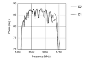
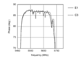
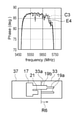
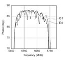
- FIGS. 4A and 4B are diagrams showing the characteristics of the resonator according to the comparative example and the embodiment.
- the horizontal axis indicates frequency.
- the vertical axis shows the impedance phase.
- the resonator 7 has a resonance frequency at which the absolute value of impedance is the minimum value and an antiresonance frequency at which the absolute value of impedance is the maximum value.
- the range between the resonance frequency and the antiresonance frequency it is said that the closer the impedance phase is to 90 °, the better the characteristics of the resonator 7. Further, outside the above range, the closer the impedance phase is to ⁇ 90 °, the better the characteristics of the resonator 7.
- the range on the horizontal axis generally corresponds to the range between the resonant frequency and the antiresonant frequency.
- FIG. 4A the characteristics of the first comparative example C1 and the second comparative example C2 are shown.
- the electrode finger 19 does not have the widening portion 19b.
- the edge portion 33a of the cavity 33 is located outside the IDT electrode 11.
- the edge portion 33a of the cavity 33 overlaps with the IDT electrode 11 as in the embodiment. Conditions other than the above are the same between the two comparative examples.
- both the first comparative example C1 and the second comparative example C2 there is a frequency in which the impedance phase specifically decreases within the frequency range in which the impedance phase should be 90 °. That is, a horizontal mode spurious is generated.
- the size and number of spurious are substantially the same in the first comparative example C1 and the second comparative example C2.
- the electrode finger 19 having no widening portion 19b is provided, whether or not the edge portion 33a of the cavity 33 overlaps with the IDT electrode 11 is determined with respect to the reduction of spurious in the transverse mode. There is no significant difference.
- FIG. 4B the characteristics of the third comparative example C3 and the first embodiment E1 are shown.
- the electrode finger 19 has the widening portion 19b as in the embodiment.
- the edge portion 33a of the cavity 33 is located outside the IDT electrode 11.
- the edge portion 33a of the cavity 33 overlaps with the IDT electrode 11 as in the embodiment. Conditions other than the above are the same among the three Comparative Examples and the First Example E1.
- the edge portion 33a on the bus bar 17 side of the cavity 33 is located in the arrangement region of the IDT electrode 11, and that the plurality of electrode fingers 19 of the IDT electrode 11 have the widening portion 19b.
- the size of the spurious is reduced for the first time by the combination with the matter. The reason is not always clear.
- the widening portion 19b reduces the speed of sound in the region outside the central region R4 by increasing the mass per unit length of the electrode finger 19 in the D2 direction.
- the support 29 reduces the speed of sound in the piezoelectric layer 31.
- the reason is that the boundary condition between the central region R4 and the region outside the central region R4 is conspicuous and the spurious in the transverse mode is reduced by superimposing both of them. For this reason, the length of the widening portion 19b in the D2 direction and the amount d of the support 29 penetrating into the IDT electrode 11 may be small. This is because the spurious in the transverse mode is still reduced to some extent.
- the edge 33a of the cavity 33 may be located inside the central region R4 rather than the edge on the bus bar 17 side of the central region R4.
- the area of the central region R4 is reduced.
- the impedance phase is lowered as a whole. Therefore, the limit position on the central region R4 side of the edge portion 33a may be the edge portion of the central region R4.
- Piezoelectric layer 31 Material: LN Cut angle: 105 ° rotation Y cut X propagation Thickness: 0.44 ⁇ m
- Cavity layer 37 Material: Si IDT electrode 11: Material: Al Thickness: 0.11 ⁇ m
- Pitch p 1.0 ⁇ m Width of bus bar 17: 1.5 ⁇ m Width of intersection area
- R6 40p Width of outer region
- R5 4.32 ⁇ m Width of dummy region
- R1 4 ⁇ m Width of gap region
- the thickness of the cavity layer 37 was set to be relatively thick. That is, it was assumed that the material of the support substrate 35 does not affect the boundary conditions of elastic waves.
- the conditions of the electrode finger 19 in the second comparative example C2, the third comparative example C3, and the first embodiment E1 are as follows.
- the entire Duty of the electrode finger 19 in the first Comparative Example C1 is the Duty of the main portion 19a.
- the configuration of the resonator 7 is the configuration exemplified in FIGS. 1, 2 and 3A (or FIG. 3B) unless otherwise specified.
- the various regions (R1 to R6) and the cavity 33 have a rectangular shape having long sides parallel to the propagation direction (D1 direction) of elastic waves.
- the widening portion 19b is provided on the root side of the electrode finger 19 and extends over a range (R1 + R2 + R3) from the bus bar 17 to the edge portion of the central region R4 on the bus bar 17 side.
- the edge 33a on the bus bar 17 side of the cavity 33 is set at an appropriate position within the range from the edge on the bus bar 17 side of the central region R4 to the edge on the outside of the bus bar 17 (opposite to the central region R4). You can do it. Within this range, for example, the effect of reducing spurious in the transverse mode is expected.
- examples of the characteristics of the resonator 7 will be shown for a plurality of cases in which the positions of the edge portions 33a (the amount of penetration d from another viewpoint) are different from each other.
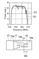
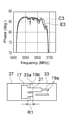
- FIGS. 5A to 5C and FIGS. 6A to 6C are diagrams showing the results of simulation calculations for the characteristics of the resonator 7.
- the upper part is the same as FIGS. 4A and 4B.
- the lower part schematically shows the positional relationship between the edge portion 33a of the cavity 33 and the IDT electrode 11.
- FIG. 5A corresponds to a comparative example (the third comparative example C3 described above) in which the edge portion 33a of the cavity 33 is located outside the IDT electrode 11.
- FIG. 5B corresponds to an embodiment in which the edge portion 33a is located on the outer edge portion of the bus bar 17 (the above-described first embodiment E1).
- FIG. 5C corresponds to the second embodiment E2 in which the edge portion 33a is located in the middle of the bus bar 17.
- FIG. 6A corresponds to the third embodiment E3 in which the edge portion 33a is located in the dummy region R1.
- FIG. 6B corresponds to the fourth embodiment E4 in which the edge portion 33a is located at the edge portion of the intersection region R6.
- FIG. 6C corresponds to the fifth embodiment E5 in which the edge portion 33a is located at the edge portion of the central region R4.
- the conditions other than the position of the edge 33a of the cavity 33 are the same between the above-mentioned one comparative example and the five embodiments, and are the same as the conditions of the first embodiment E1 described with reference to FIG. 4B. Is.
- the distance between the edge portion 33a and the bus bar 17 is 1 ⁇ m.
- the amount of the cavity layer 37 (edge 33a) invading the central region R4 side from the outer edge of the bus bar 17 is 0 ⁇ m.
- the penetration amount d is 1 ⁇ m.
- the intrusion amount d is 3 ⁇ m.
- the intrusion amount d is 5.82 ⁇ m.
- the intrusion amount d is 7.5 ⁇ m.
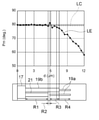
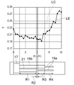
- Evaluation index An evaluation index for evaluating the characteristics of the resonator 7 is defined. Then, based on this evaluation index, the influence of the position of the edge 33a on the bus bar 17 side of the cavity 33 on the characteristics of the resonator 7 is examined in detail.
- phase average value Pm is the value obtained by averaging the impedance phases over the frequency range from the resonance frequency to the antiresonance frequency.
- the overall magnitude of the impedance phase shall be evaluated by this phase mean value Pm.
- the value obtained by averaging the absolute value of the rate of change in the change of the impedance phase with respect to the change in frequency over the frequency range from the resonance frequency to the antiresonance frequency is used as the index T of the transverse mode.
- Transverse mode spurious shall be evaluated by this index T.
- the index T is 0.
- the changes in the phase mean value Pm and the index T with respect to the change in the intrusion amount d were obtained by simulation calculation for each material of the cavity layer 37.
- the simulation conditions are the same among the plurality of simulation cases except for the material of the cavity layer 37 and the penetration amount d, and are the same as the simulation cases described with reference to FIGS. 4A to 6C.
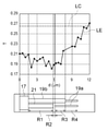
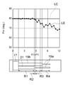
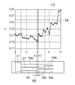
- (Si) 7A and 7B are diagrams showing the characteristics of the resonator 7 in which the material of the cavity layer 37 is Si.
- the horizontal axis shows the intrusion amount d.
- the vertical axis indicates the index T.
- the vertical axis shows the phase mean value Pm.
- the lower part of FIGS. 7A and 7B schematically shows the shape of the IDT electrode 11.
- the position of the horizontal axis in the upper row and the position in the horizontal direction in the IDT electrode 11 in the lower row correspond to each other.
- 0 ⁇ m in the upper row corresponds to the outer edge of the bus bar 17 in the lower row.
- the upper 1.5 ⁇ m corresponds to the inner edge of the lower bus bar 17.
- the line LE shows the characteristics of the embodiment.
- the line LC shows the characteristics of the comparative example. That is, the line LC shows the value of the index T or the phase average value Pm when the intrusion amount d is a negative value (more specifically, -1 ⁇ m) regardless of the position on the horizontal axis.
- the change in the index T with respect to the change in the intrusion amount d is as follows.
- the index T is smaller than the index T in the comparative example.
- the index T generally decreases.
- the edge 33a of the cavity 33 approaches the gap region R2
- the index T stops lowering. After that, the index T increases slightly before the edge portion 33a reaches the central region R4.
- the edge portion 33a is located in the central region R4 and the intrusion amount d is further increased, the index T becomes larger than the index T in the comparative example.
- the relationship between the range where the edge 33a of the cavity 33 is located and the size of the index T is as follows.
- the index T is reduced as compared with the comparative example.
- the index T is roughly equal to or smaller than the size when the intrusion amount d is 0 ⁇ m. More strictly, when the edge portion 33a is located in the range of R1 + R2, the index T is equal to or less than the size when the intrusion amount d is 0 ⁇ m.
- the index T is the smallest.
- a range having a width of about 10 times the width of the gap region R2 centered on the gap region R2 can be mentioned.
- a range of the dummy region R1 adjacent to the gap region R2 and having a width of about 5 times the gap region R2 can be mentioned.
- the change in the phase mean value Pm with respect to the change in the intrusion amount d is as follows.
- the phase mean value Pm is substantially the same as the phase mean value Pm of the comparative example (slightly larger). Even if the intrusion amount d increases from 0 ⁇ m, the phase mean value Pm does not change significantly, and a state substantially equivalent to the phase mean value Pm of the comparative example is maintained. After that, the phase average value Pm decreases slightly before the edge portion 33a of the cavity 33 reaches the central region R4. Then, the phase mean value Pm is smaller than the phase mean value Pm of the comparative example.
- phase mean value Pm is the phase mean value Pm of the comparative example. Generally equal or better. Further, when the edge portion 33a is located in the range of R1 + R2, the phase mean value Pm is larger than the phase mean value Pm of the comparative example.
- (SiO 2 ) 8A and 8B are diagrams showing the characteristics of the resonator 7 in which the cavity layer 37 has a first layer 37a made of Si and a second layer 37b made of SiO 2 , and is similar to FIGS. 7A and 7B. It is a figure of.
- the thickness of the second layer 37b is 0.1 ⁇ m.
- the change in the index T with respect to the change in the intrusion amount d is substantially the same as in FIG. 7A.
- the rise of the index T starts earlier after the edge portion 33a of the cavity 33 is close to the gap region R2 and the index T stops lowering.
- the relationship between the range where the edge 33a of the cavity 33 is located and the size of the index T is as follows.
- the index T is reduced as compared with the comparative example as in FIG. 7A.
- the index T is not smaller than the size when the intrusion amount d is 0 ⁇ m.
- the index T is equal to or smaller than the size when the intrusion amount d is 0 ⁇ m, as in FIG. 7A.
- the index T is the smallest.
- a range of the dummy area R1 that is adjacent to the gap area R2 and has a width of about 5 times the gap area R2 can be mentioned.
- the relationship between the range where the edge 33a of the cavity 33 is located and the size of the phase average value Pm is as follows.
- the phase mean value Pm is the phase mean value Pm of the comparative example. It is almost the same.
- (Low resistance layer) 9A and 9B are diagrams showing the characteristics of the resonator 7 in which the cavity layer 37 has a first layer 37a made of Si and a second layer 37b made of a low resistance layer. It is a similar figure.
- the thickness of the second layer 37b is 2 nm.
- the resistivity of the second layer 37b is 2.5 ⁇ ⁇ cm at 5500 MHz. That is, the sheet resistance of the second layer 37b is 1.25 ⁇ 107 ⁇ .
- the sheet resistance of the second layer 37b is adjusted by subjecting the upper surface of the first layer 37a to a predetermined treatment, and its density and elastic modulus are substantially the same as those of Si.
- FIG. 9A the change in the index T with respect to the change in the intrusion amount d, and the relationship between the range where the edge 33a of the cavity 33 is located and the size of the index T are substantially the same as those in FIG. 7A.
- FIG. 9B the change in the phase average value Pm with respect to the change in the intrusion amount d, and the relationship between the range where the edge portion 33a of the cavity 33 is located and the size of the phase average value Pm are substantially the same as in FIG. 7B.
- (AlN) 10A and 10B are diagrams showing the characteristics of the resonator 7 in which the cavity layer 37 has a first layer 37a made of Si and a second layer 37b made of AlN, and is similar to FIGS. 7A and 7B. It is a figure.
- the thickness of the second layer 37b is 0.1 ⁇ m.
- the change in the index T with respect to the change in the intrusion amount d, and the relationship between the range where the edge 33a of the cavity 33 is located and the size of the index T are substantially the same as those in FIG. 8A.
- the index T is defined as the smallest range, for example, the range described in FIG. 8A (the range of the dummy area R1 that is adjacent to the gap area R2 and has a width of about 5 times the gap area R2).
- a range in which half of the gap region R2 on the dummy region R1 side is added to the range can be mentioned.
- the change in the phase mean value Pm with respect to the change in the intrusion amount d, and the relationship between the range where the edge 33a of the cavity 33 is located and the size of the phase mean value Pm are substantially the same as in FIG. 8B.
- FIGS. 7A and 7B are diagrams showing the characteristics of the resonator 7 in which the cavity layer 37 has a first layer 37a made of Si and a second layer 37b made of HfO 2 , and is similar to FIGS. 7A and 7B. It is a figure of.
- the thickness of the second layer 37b is 0.1 ⁇ m.
- the change in the index T with respect to the change in the intrusion amount d is substantially the same as in FIG. 8A.
- the index T when the intrusion amount d is 0 is different from the previous examples and is substantially the same as the index T of the comparative example. Further, when the decrease of the index T stops decreasing and then increases, it becomes equivalent to the value of the index T of the comparative example earlier than the previous examples.
- the relationship between the range where the edge 33a of the cavity 33 is located and the size of the index T is as follows.
- the index T is roughly equal to or less than the index T of the comparative example. be.
- the index T is roughly equal to or smaller than the size when the intrusion amount d is 0 ⁇ m.
- the index T is the smallest when the edge 33a is within the range of the gap region R2 and / or its surroundings.
- a range similar to that in FIG. 8A (a range of the dummy area R1 adjacent to the gap area R2 and having a width of about 5 times the gap area R2) can be mentioned. can.
- HfO 2 is a relatively high density material.
- the densities of LN and LT are 4 g / cm 3 or more and 8 g / cm 3 or less.
- the density of HfO 2 is 9 g / cm 3 or more and 11 g / cm 3 or less.
- the densities of Si, SiO 2 and AlN are 2 g / cm 3 or more and 4 g / cm 3 or less. Therefore, the material constituting the upper surface of the support 29 (for example, the entire cavity layer 37 or the second layer 37b) may be, for example, a material having a density smaller than the density of the material of the piezoelectric layer 31.
- Si (FIG. 7A) and SiO 2 (FIG. 8A) have relatively close densities (2 g / cm 3 or more and 3 g / cm 3 or less).
- the material of the cavity layer 37 is Si
- the value of the index T itself is small
- the amount of reduction of the index T with respect to the index T of the comparative example is large
- the range is wide. The reason is that the speed of sound in SiO 2 is relatively low, and elastic waves leaking from the central region R4 tend to concentrate in the portion near the edge 33a of the cavity layer 37.
- the speed of sound of SiO 2 (square root of the value obtained by dividing the elastic modulus by the density) is 5000 m / s or more and 6000 m / s or less, and the speed of sound of Si is 7000 m / s or more and 9000 m / s or less. Therefore, the material constituting the upper surface of the support 29 (for example, the entire cavity layer 37 or the second layer 37b) may be, for example, a material having a sound velocity of 7,000 m / s or more.
- the duty of the widening portion 19b was set to 0.60.
- the characteristics obtained by the simulation calculation are shown for the case where the Duty of the widening portion 19b is different from 0.60.
- the conditions other than the duty of the widening portion 19b are the same as those in FIG. 7A.
- the cavity layer 37 is entirely composed of Si.
- 12A and 12B are diagrams showing the characteristics of the resonator 7 having a duty of 0.70 in the widening portion 19b, and are the same diagrams as those in FIGS. 7A and 7B.
- 13A and 13B are diagrams showing the characteristics of the resonator 7 having a duty of 0.80 in the widening portion 19b, and are the same views as those in FIGS. 7A and 7B.
- the same tendency as in FIGS. 7A and 7B can be seen for the index T and the phase mean value Pm.
- the position of the edge 33a of the cavity 33 where the index T is the minimum is the position adjacent to the gap region R2 in the dummy region R1
- the index is The position of the edge portion 33a where T is the minimum is located in the end region R3.
- the position of the edge portion 33a where the index T is the minimum is located in the widening portion 19b.
- FIG. 7A is the smallest.
- FIG. 14B is a diagram similar to FIG. 4A showing the characteristics of the first comparative example C1 of FIG. 4A and the fourth embodiment E4 of FIG. 6B.
- the electrode finger 19 does not have the widening portion 19b, and the edge portion 33a of the cavity 33 is located outside the arrangement region of the IDT electrode 11. ing.
- the width of the bus bar 17 is 1.5 ⁇ m.
- FIG. 14A is a diagram similar to FIG. 4A showing the characteristics of the fourth comparative example C4 and the sixth embodiment E6.
- the width of the bus bar 17 is 0.3 ⁇ m.
- Other conditions in the fourth comparative example C4 are the same as those in the first comparative example C1.
- Other conditions in the sixth embodiment E6 are the same as those in the fourth embodiment E4.
- the edge 33a of the cavity 33 is located in the arrangement region of the IDT electrode 11, and the widening portion 19b is provided on the electrode finger 19, so that the width of the bus bar 17 does not depend on the width of the bus bar 17. The effect of reducing the spurious of the mode can be obtained.
- 15A and 15B are diagrams showing changes in the characteristics of the resonator 7 with respect to changes in the width of the bus bar 17.
- the horizontal axis BW indicates the width of the bus bar 17.
- the vertical axis of FIG. 15A indicates the index T.
- the vertical axis of FIG. 15B shows the phase mean value Pm.
- the polygonal line in the figure shows the characteristics in the embodiment. Further, in the figure, points showing the characteristics of the first Comparative Example C1, the fourth Example E4, the fourth Comparative Example C4, and the sixth Example E6 shown in FIGS. 14A and 14B are shown. From these figures, it can be seen that the actions described so far do not depend on the width of the bus bar 17.
- the elastic wave element 1 has a support 29, a piezoelectric layer 31 on the support 29, and an IDT electrode 11 on the piezoelectric layer 31.
- a cavity 33 that overlaps with the IDT electrode 11 in planar fluoroscopy is formed between the piezoelectric layer 31 and the support 29.
- the IDT electrode 11 has a first bus bar and a second bus bar (bus bars 17A and 17B), and a plurality of first electrode fingers and a plurality of second electrode fingers (electrode fingers 19A and 19B).
- the bus bars 17A and 17B face each other in the direction (D2 direction) intersecting the first direction (D1 direction).
- the plurality of electrode fingers 19A extend in parallel with each other from the bus bar 17A toward the bus bar 17B.
- the plurality of electrode fingers 19B extend in parallel with each other from the bus bar 17B toward the bus bar 17A.
- the plurality of electrode fingers 19A and the plurality of electrode fingers 19B are alternately arranged in the D1 direction.
- a region extending along an array of a plurality of electrode fingers 19A and a plurality of electrode fingers 19B at an intersecting width in which the electrode fingers 19A and the electrode fingers 19B adjacent to each other overlap each other when viewed in the D1 direction. Is referred to as an intersection region R6.
- the intersecting region R6 has a central region R4 and a first end region and a second end region (two end regions R3).
- the central region R4 includes a central position between the two bus bars 17.
- Each end region R3 is a region from the edge portion of the central region R4 on the bus bar 17 side to the edge portion of the intersection region R6 on the bus bar 17 side.
- the cavity 33 overlaps the central region R4.
- the edge of the cavity 33 on the bus bar 17A side is located within a range from the edge of the central region R4 on the bus bar 17A side to the edge of the bus bar 17A on the opposite side (outer side) of the central region R4.
- Each of the plurality of electrode fingers 19A has a first portion (main portion 19a) and a second portion (widening portion 19b).
- the main portion 19a is located in the central region R4.
- the widened portion 19b of the electrode finger 19A is located on the bus bar 17A side or the bus bar 17B side (in this embodiment, the bus bar 17A side) with respect to the central region R4.
- the mass on the lower surface of the plurality of electrode fingers 19A per unit length in the second direction (D2 direction) orthogonal to the D1 direction has a larger value in the widening portion 19b than in the main portion 19a.
- the widening portion 19b can reduce the speed of sound in the region where the IDT electrode 11 is arranged and in the region outside the central region R4. Further, the support 29 can reduce the speed of sound in the region where the IDT electrode 11 is arranged and in the region outside the central region R4. And, by this combination, the spurious of the transverse mode can be reduced.
- the width of the second portion may be wider than the width of the first portion (main portion 19a).
- the mass per unit length of the second portion can be increased by patterning the conductor layer 5.
- the embodiment may also be included in the technique according to the present disclosure.
- the mass per unit length can be easily increased. As a result, it is advantageous in terms of cost.
- the widened portion 19b of the electrode finger 19A may be located on the bus bar 17A side with respect to the central region R4. That is, the widening portion 19b may be located on the root side of the electrode finger 19.
- a second portion (widening portion 19b) is provided on the tip end side of the electrode finger 19 (this aspect is also included in the technique according to the present disclosure). Good), it is easier to reduce the spurious in the transverse mode.
- the second portion is provided on the tip side in addition to the root side of the electrode finger 19, for example, the characteristics on the higher frequency side than the antiresonance frequency are improved.
- the widening portion 19b of the electrode finger 19A may extend from the bus bar 17A to the edge of the central region R4 on the bus bar 17A side (R1 + R2 + R3).
- the spurious in the transverse mode is reduced as compared with the embodiment in which the widening portion 19b is located only in a part of the range of R1 + R2 + R3 (the embodiment may also be included in the technique according to the present disclosure). The effect is improved.
- the edge 33a on the bus bar 17A side of the cavity 33 is located at any position in the range from the edge of the crossing region R6 on the bus bar 17A side to the edge of the bus bar 17A on the opposite side (outer side) of the central region R4. You can do it.
- the IDT electrode 11 may have a first dummy electrode and a second dummy electrode (dummy electrodes 21A and 21B).
- the dummy electrode 21A projects from the bus bar 17A toward the bus bar 17B between the plurality of electrode fingers 19A, and the tips of the dummy electrodes 21A face each other with the plurality of electrode fingers 19B. The same applies to the dummy electrode 21B.
- the edge 33a on the bus bar 17A side of the cavity 33 is located at any position in the range (R1 + R2) from the tips of the plurality of dummy electrodes 21A to the edge on the opposite side (outside) of the central region R4 of the bus bar 17A. You can do it.
- the above-mentioned effect is further improved. That is, there is a high probability that the effect of reducing spurious in the transverse mode will be achieved. The probability that the phase mean value Pm becomes small is reduced.
- the Duty of the widening portion 19b is set so that the effect of reducing the spurious in the transverse mode is relatively large, it is facilitated to minimize the spurious in the transverse mode.
- the edge 33a on the bus bar 17A side of the cavity 33 is located at any position in the range (R1 + R2 + R3) from the edge of the central region R4 on the bus bar 17A side to the edge of the bus bar 17A on the central region R4 side (inside). You can do it.
- the index T tends to become smaller as the intrusion amount d increases from 0 ⁇ m, so that it is easy to minimize the spurious in the transverse mode.
- the material, cut angle, and thickness of the piezoelectric layer 31 may have a relationship in which the amplitude of the A1 mode lamb wave is the largest among the elastic waves excited by the IDT electrode 11. That is, the element 1 may utilize the A1 mode lamb wave.
- the support 29 constitutes the upper surface of the support 29 and has a layer whose density is lower than the density of the piezoelectric layer 31 (for example, the entire support 29, the cavity layer 37 or the second layer 37b). It's okay. And / or the support 29 constitutes the upper surface of the support 29 and has a layer having a sound velocity of 7,000 m / s or more (for example, the entire support 29, the cavity layer 37 or the second layer 37b). You can do it.
- the effect of reducing spurious in the transverse mode can be improved.
- the range of the intrusion amount d from which the effect of reducing spurious in the transverse mode can be obtained can be widened.
- the elastic wave element may utilize a so-called piston mode. Even in this case, the same effect as that of the first embodiment is obtained. Specifically, it is as follows.
- 16A and 16B are diagrams showing the characteristics of the resonator according to the second embodiment, and are the same diagrams as those of FIGS. 7A and 7B.
- the bus bar 217 has a plurality of (only one is shown) openings 217h arranged in the propagation direction of elastic waves (vertical direction on the paper surface). ing. Further, the dummy electrode 21 (in other words, the dummy region R1) is not provided.
- the electrode finger 19 has a widening portion 19c not only on the root side but also on the tip side. As shown in the upper part of FIGS. 16A and 16B, the same tendency as that of the first embodiment was confirmed with respect to the index T and the phase mean value Pm even with the above configuration.
- FIG. 17 is a circuit diagram schematically showing the configuration of a duplexer 101 (for example, a duplexer) as a usage example of the element 1.
- a duplexer 101 for example, a duplexer
- the comb tooth electrode 15 is schematically shown by a bifurcated fork shape, and the reflector 13 is a single line with both ends bent. It is represented by.
- the demultiplexer 101 for example, has a transmission filter 109 that filters the transmission signal from the transmission terminal 105 and outputs the signal to the antenna terminal 103, and the demultiplexer 101 filters the reception signal from the antenna terminal 103 and outputs the signal to the pair of reception terminals 107. It has a reception filter 111.
- the transmission filter 109 is composed of, for example, a ladder type filter in which a plurality of resonators 7 (7S and 7P) are connected in a ladder type. That is, the transmission filter 109 includes a plurality of (or even one) series resonators 7S connected in series between the transmission terminal 105 and the antenna terminal 103, a line (series arm) thereof, and a reference potential portion (a reference potential portion). It has a plurality of (or even one) parallel resonators 7P (parallel arms) connecting the reference numerals (omitted).
- the reception filter 111 is configured to include, for example, a resonator 7 and a multiple mode type filter (including a double mode type filter) 113.
- the multimode filter 113 has a plurality of (three in the illustrated example) IDT electrodes 11 arranged in the propagation direction of elastic waves, and a pair of reflectors 13 arranged on both sides thereof.
- the plurality of IDT electrodes 11 (and reflectors 13) of the duplexer 101 may be provided on one composite substrate 3 or may be dispersedly provided on two or more composite substrates 3.
- the plurality of resonators 7 constituting the transmission filter 109 may be provided on the same composite substrate 3.
- the resonator 7 and the multiple mode filter 113 constituting the reception filter 111 may be provided on the same composite substrate 3, for example.
- the transmission filter 109 and the reception filter 111 may be provided on the same composite substrate 3 or on different composite substrates 3 from each other, for example.
- a plurality of series resonators 7S may be provided on the same composite substrate 3, and a plurality of parallel resonators 7P may be provided on another same composite substrate 3.
- FIG. 17 is just an example of the configuration of the demultiplexer 101. Therefore, for example, the reception filter 111 may be configured by a ladder type filter like the transmission filter 109. Further, the transmission filter 109 may have a multiple mode type filter 113.
- the duplexer 101 is not limited to the duplexer, and may be, for example, a duplexer or a multiplexer including three or more filters.
- the resonator 7 and the multiple mode filter 113 may be regarded as the element 1, respectively. Further, each of the transmission filter 109 and the reception filter 111 may be regarded as the element 1. Further, the duplexer 101 may be regarded as the element 1.
- FIG. 18 is a block diagram showing a main part of the communication device 151 as a usage example of the element 1 (from another viewpoint, the duplexer 101).
- the communication device 151 performs wireless communication using radio waves, and includes a demultiplexer 101.
- the transmission information signal TIS including information to be transmitted is modulated and frequency-raised (converted to a high-frequency signal having a carrier frequency) by an RF-IC (Radio Frequency Integrated Circuit) 153, and the transmission signal TS is performed. It is said that.
- the transmission signal TS has unnecessary components other than the pass band for transmission removed by the bandpass filter 155, is amplified by the amplifier 157, and is input to the demultiplexer 101 (transmission terminal 105). Then, the demultiplexer 101 (transmission filter 109) removes unnecessary components other than the passing band for transmission from the input transmission signal TS, and outputs the removed transmission signal TS from the antenna terminal 103 to the antenna 159. ..
- the antenna 159 converts the input electric signal (transmission signal TS) into a radio signal (radio wave) and transmits the radio signal (radio wave).
- the radio signal (radio wave) received by the antenna 159 is converted into an electric signal (received signal RS) by the antenna 159 and input to the demultiplexer 101 (antenna terminal 103).
- the demultiplexer 101 removes unnecessary components other than the passing band for reception from the input reception signal RS and outputs the signal from the reception terminal 107 to the amplifier 161.
- the output received signal RS is amplified by the amplifier 161 and unnecessary components other than the passing band for reception are removed by the bandpass filter 163. Then, the frequency of the received signal RS is reduced and demodulated by the RF-IC153 to obtain the received information signal RIS.
- the transmission information signal TIS and the reception information signal RIS may be low frequency signals (baseband signals) containing appropriate information, and are, for example, analog audio signals or digitized audio signals.
- the pass band of the radio signal may be appropriately set and may follow various known standards.
- the modulation method may be phase modulation, amplitude modulation, frequency modulation, or a combination of any two or more of these.
- the direct conversion system is exemplified as the circuit system, other appropriate circuit systems may be used, and for example, a double superheterodyne system may be used.
- FIG. 18 schematically shows only the main part, and a low-pass filter, an isolator, or the like may be added at an appropriate position, or the position of the amplifier or the like may be changed.
- the bus bar 17A and the bus bar 217 are examples of the first bus bar, respectively.
- the bus bar 17B and the bus bar 217 are examples of the second bus bar, respectively.
- the electrode finger 19A is an example of the first electrode finger.
- the electrode finger 19B is an example of the second electrode finger.
- the end region R3 on the bus bar 17A side is an example of the first end region.
- the end region R3 on the bus bar 17B side is an example of the second end region.
- the main part 19a is an example of the first part.
- the widening portion 19b and the widening portion 19c are examples of the second portion, respectively.
- the dummy electrode 21A is an example of the first dummy electrode.
- the dummy electrode 21B is an example of the second dummy electrode.
- RF-IC153 is an example of an integrated circuit element.
- the method of increasing the mass on the lower surface of the electrode finger at the second portion per unit length in the second direction is not limited to the method of using the second portion as the widening portion.
- the thickness of the second part may be made thicker than the thickness of the first part, or an insulating or conductive additional film may be provided only on the second part of the first part and the second part. It's okay.
- the portion on the second portion may be made thicker than the portion on the first portion. Two or more of the methods described so far may be combined.
- the mass on the lower surface of the electrode finger may include not only the mass of the electrode finger itself but also the mass of the member overlapping the electrode finger.
- the widening portion is provided on both the first electrode finger and the second electrode finger. Further, both the edge of the cavity on the first busbar side and the edge of the cavity on the second busbar side overlapped with the IDT electrode. However, the widening portion is provided only on one of the first electrode finger and the second electrode finger, and / or only one of the edge portion on the first bus bar side and the edge portion on the second bus bar side overlaps with the IDT electrode. You may. The range of positions of the edges of the cavities examined with reference to FIGS. 7A-16B may be combined with an electrode shape different from the illustrated example.
Landscapes
- Physics & Mathematics (AREA)
- Acoustics & Sound (AREA)
- Surface Acoustic Wave Elements And Circuit Networks Thereof (AREA)
Priority Applications (4)
| Application Number | Priority Date | Filing Date | Title |
|---|---|---|---|
| US18/023,535 US12489418B2 (en) | 2020-08-28 | 2021-08-27 | Elastic wave element and communication device |
| JP2022545742A JPWO2022045307A1 (https=) | 2020-08-28 | 2021-08-27 | |
| CN202180051011.0A CN116097565A (zh) | 2020-08-28 | 2021-08-27 | 弹性波元件以及通信装置 |
| US19/370,923 US20260051871A1 (en) | 2020-08-28 | 2025-10-28 | Elastic wave element and communication device |
Applications Claiming Priority (2)
| Application Number | Priority Date | Filing Date | Title |
|---|---|---|---|
| JP2020144341 | 2020-08-28 | ||
| JP2020-144341 | 2020-08-28 |
Related Child Applications (2)
| Application Number | Title | Priority Date | Filing Date |
|---|---|---|---|
| US18/023,535 A-371-Of-International US12489418B2 (en) | 2020-08-28 | 2021-08-27 | Elastic wave element and communication device |
| US19/370,923 Continuation US20260051871A1 (en) | 2020-08-28 | 2025-10-28 | Elastic wave element and communication device |
Publications (1)
| Publication Number | Publication Date |
|---|---|
| WO2022045307A1 true WO2022045307A1 (ja) | 2022-03-03 |
Family
ID=80355405
Family Applications (1)
| Application Number | Title | Priority Date | Filing Date |
|---|---|---|---|
| PCT/JP2021/031584 Ceased WO2022045307A1 (ja) | 2020-08-28 | 2021-08-27 | 弾性波素子及び通信装置 |
Country Status (4)
| Country | Link |
|---|---|
| US (2) | US12489418B2 (https=) |
| JP (1) | JPWO2022045307A1 (https=) |
| CN (1) | CN116097565A (https=) |
| WO (1) | WO2022045307A1 (https=) |
Cited By (4)
| Publication number | Priority date | Publication date | Assignee | Title |
|---|---|---|---|---|
| WO2023195523A1 (ja) * | 2022-04-08 | 2023-10-12 | 株式会社村田製作所 | 弾性波装置 |
| JPWO2023243351A1 (https=) * | 2022-06-17 | 2023-12-21 | ||
| WO2024034528A1 (ja) * | 2022-08-12 | 2024-02-15 | 京セラ株式会社 | 弾性波装置、複合フィルタ及び通信装置 |
| WO2024101338A1 (ja) * | 2022-11-08 | 2024-05-16 | 京セラ株式会社 | 弾性波共振子および通信装置 |
Families Citing this family (1)
| Publication number | Priority date | Publication date | Assignee | Title |
|---|---|---|---|---|
| US12609671B2 (en) * | 2024-03-18 | 2026-04-21 | Rf360 Singapore Pte. Ltd. | High Q electroacoustic resonator |
Citations (6)
| Publication number | Priority date | Publication date | Assignee | Title |
|---|---|---|---|---|
| JP2007312164A (ja) * | 2006-05-19 | 2007-11-29 | Hitachi Ltd | 圧電薄膜共振器並びにそれを用いた高周波フィルタ及び高周波モジュール |
| JP2012257019A (ja) * | 2011-06-08 | 2012-12-27 | Murata Mfg Co Ltd | 弾性波装置 |
| WO2018003338A1 (ja) * | 2016-06-27 | 2018-01-04 | 株式会社村田製作所 | 弾性波フィルタ装置 |
| WO2019065666A1 (ja) * | 2017-09-27 | 2019-04-04 | 株式会社村田製作所 | 弾性波装置 |
| WO2020100949A1 (ja) * | 2018-11-14 | 2020-05-22 | 京セラ株式会社 | 弾性波装置、分波器および通信装置 |
| WO2020116528A1 (ja) * | 2018-12-06 | 2020-06-11 | 株式会社村田製作所 | 弾性波装置 |
Family Cites Families (8)
| Publication number | Priority date | Publication date | Assignee | Title |
|---|---|---|---|---|
| WO2013150814A1 (ja) * | 2012-04-04 | 2013-10-10 | 株式会社村田製作所 | 通信装置 |
| JP5436729B1 (ja) * | 2012-04-25 | 2014-03-05 | 京セラ株式会社 | 弾性波素子、分波器および通信モジュール |
| WO2014133084A1 (ja) * | 2013-02-27 | 2014-09-04 | 京セラ株式会社 | 弾性波素子、分波器および通信モジュール |
| US9281800B2 (en) * | 2014-01-24 | 2016-03-08 | Avago Technologies General Ip (Singapore) Pte. Ltd. | Resonator filter device having narrow pass-band |
| US9691963B2 (en) * | 2014-05-29 | 2017-06-27 | Avago Technologies General Ip (Singapore) Pte. Ltd. | Capacitive coupled resonator and filter device with comb electrodes and support pillars separating piezoelectric layer |
| DE112016001894B4 (de) * | 2015-04-24 | 2022-02-03 | Murata Manufacturing Co., Ltd. | Vorrichtung für elastische Wellen |
| US9660349B2 (en) * | 2015-06-29 | 2017-05-23 | Northrop Grumman Systems Corporation | Multiferroic surface acoustic wave antenna |
| CN105337586B (zh) * | 2015-12-03 | 2018-04-17 | 天津大学 | 兰姆波谐振器 |
-
2021
- 2021-08-27 CN CN202180051011.0A patent/CN116097565A/zh active Pending
- 2021-08-27 WO PCT/JP2021/031584 patent/WO2022045307A1/ja not_active Ceased
- 2021-08-27 US US18/023,535 patent/US12489418B2/en active Active
- 2021-08-27 JP JP2022545742A patent/JPWO2022045307A1/ja active Pending
-
2025
- 2025-10-28 US US19/370,923 patent/US20260051871A1/en active Pending
Patent Citations (6)
| Publication number | Priority date | Publication date | Assignee | Title |
|---|---|---|---|---|
| JP2007312164A (ja) * | 2006-05-19 | 2007-11-29 | Hitachi Ltd | 圧電薄膜共振器並びにそれを用いた高周波フィルタ及び高周波モジュール |
| JP2012257019A (ja) * | 2011-06-08 | 2012-12-27 | Murata Mfg Co Ltd | 弾性波装置 |
| WO2018003338A1 (ja) * | 2016-06-27 | 2018-01-04 | 株式会社村田製作所 | 弾性波フィルタ装置 |
| WO2019065666A1 (ja) * | 2017-09-27 | 2019-04-04 | 株式会社村田製作所 | 弾性波装置 |
| WO2020100949A1 (ja) * | 2018-11-14 | 2020-05-22 | 京セラ株式会社 | 弾性波装置、分波器および通信装置 |
| WO2020116528A1 (ja) * | 2018-12-06 | 2020-06-11 | 株式会社村田製作所 | 弾性波装置 |
Cited By (5)
| Publication number | Priority date | Publication date | Assignee | Title |
|---|---|---|---|---|
| WO2023195523A1 (ja) * | 2022-04-08 | 2023-10-12 | 株式会社村田製作所 | 弾性波装置 |
| JPWO2023243351A1 (https=) * | 2022-06-17 | 2023-12-21 | ||
| WO2023243351A1 (ja) * | 2022-06-17 | 2023-12-21 | 京セラ株式会社 | 弾性波装置、および通信装置 |
| WO2024034528A1 (ja) * | 2022-08-12 | 2024-02-15 | 京セラ株式会社 | 弾性波装置、複合フィルタ及び通信装置 |
| WO2024101338A1 (ja) * | 2022-11-08 | 2024-05-16 | 京セラ株式会社 | 弾性波共振子および通信装置 |
Also Published As
| Publication number | Publication date |
|---|---|
| JPWO2022045307A1 (https=) | 2022-03-03 |
| US20260051871A1 (en) | 2026-02-19 |
| US12489418B2 (en) | 2025-12-02 |
| US20240030891A1 (en) | 2024-01-25 |
| CN116097565A (zh) | 2023-05-09 |
Similar Documents
| Publication | Publication Date | Title |
|---|---|---|
| JP7433268B2 (ja) | 弾性波装置、分波器および通信装置 | |
| JP6856825B2 (ja) | 弾性波装置、分波器および通信装置 | |
| WO2022045307A1 (ja) | 弾性波素子及び通信装置 | |
| JP7278305B2 (ja) | 弾性波装置、分波器および通信装置 | |
| CN110771039B (zh) | 弹性波装置、分波器以及通信装置 | |
| JP6994855B2 (ja) | 弾性波素子、分波器および通信装置 | |
| WO2021177108A1 (ja) | 弾性波共振子、弾性波フィルタ、分波器、通信装置 | |
| JP2024125406A (ja) | 弾性波装置及び通信装置 | |
| WO2024034528A1 (ja) | 弾性波装置、複合フィルタ及び通信装置 | |
| JP2019180064A (ja) | 弾性波フィルタ、分波器および通信装置 | |
| WO2021060444A1 (ja) | 弾性波フィルタ及び通信装置 | |
| JP7630624B2 (ja) | 弾性波装置、フィルタ、分波器及び通信装置 | |
| JP7682274B2 (ja) | 弾性波装置、フィルタ、分波器及び通信装置 | |
| JP7421557B2 (ja) | 弾性波装置及び通信装置 | |
| US20250300626A1 (en) | Elastic wave element and communication device |
Legal Events
| Date | Code | Title | Description |
|---|---|---|---|
| 121 | Ep: the epo has been informed by wipo that ep was designated in this application |
Ref document number: 21861728 Country of ref document: EP Kind code of ref document: A1 |
|
| ENP | Entry into the national phase |
Ref document number: 2022545742 Country of ref document: JP Kind code of ref document: A |
|
| NENP | Non-entry into the national phase |
Ref country code: DE |
|
| 122 | Ep: pct application non-entry in european phase |
Ref document number: 21861728 Country of ref document: EP Kind code of ref document: A1 |