WO2022044970A1 - 回転機器 - Google Patents
回転機器 Download PDFInfo
- Publication number
- WO2022044970A1 WO2022044970A1 PCT/JP2021/030431 JP2021030431W WO2022044970A1 WO 2022044970 A1 WO2022044970 A1 WO 2022044970A1 JP 2021030431 W JP2021030431 W JP 2021030431W WO 2022044970 A1 WO2022044970 A1 WO 2022044970A1
- Authority
- WO
- WIPO (PCT)
- Prior art keywords
- blade
- rotating device
- blades
- rotor
- rotating body
- Prior art date
- Legal status (The legal status is an assumption and is not a legal conclusion. Google has not performed a legal analysis and makes no representation as to the accuracy of the status listed.)
- Ceased
Links
Images












Classifications
-
- H—ELECTRICITY
- H02—GENERATION; CONVERSION OR DISTRIBUTION OF ELECTRIC POWER
- H02K—DYNAMO-ELECTRIC MACHINES
- H02K9/00—Arrangements for cooling or ventilating
- H02K9/02—Arrangements for cooling or ventilating by ambient air flowing through the machine
- H02K9/04—Arrangements for cooling or ventilating by ambient air flowing through the machine having means for generating a flow of cooling medium
- H02K9/06—Arrangements for cooling or ventilating by ambient air flowing through the machine having means for generating a flow of cooling medium with fans or impellers driven by the machine shaft
-
- H—ELECTRICITY
- H02—GENERATION; CONVERSION OR DISTRIBUTION OF ELECTRIC POWER
- H02K—DYNAMO-ELECTRIC MACHINES
- H02K5/00—Casings; Enclosures; Supports
- H02K5/04—Casings or enclosures characterised by the shape, form or construction thereof
- H02K5/16—Means for supporting bearings, e.g. insulating supports or means for fitting bearings in the bearing-shields
- H02K5/173—Means for supporting bearings, e.g. insulating supports or means for fitting bearings in the bearing-shields using bearings with rolling contact, e.g. ball bearings
- H02K5/1732—Means for supporting bearings, e.g. insulating supports or means for fitting bearings in the bearing-shields using bearings with rolling contact, e.g. ball bearings radially supporting the rotary shaft at both ends of the rotor
-
- H—ELECTRICITY
- H02—GENERATION; CONVERSION OR DISTRIBUTION OF ELECTRIC POWER
- H02K—DYNAMO-ELECTRIC MACHINES
- H02K5/00—Casings; Enclosures; Supports
- H02K5/04—Casings or enclosures characterised by the shape, form or construction thereof
- H02K5/20—Casings or enclosures characterised by the shape, form or construction thereof with channels or ducts for flow of cooling medium
- H02K5/207—Casings or enclosures characterised by the shape, form or construction thereof with channels or ducts for flow of cooling medium with openings in the casing specially adapted for ambient air
-
- H—ELECTRICITY
- H02—GENERATION; CONVERSION OR DISTRIBUTION OF ELECTRIC POWER
- H02K—DYNAMO-ELECTRIC MACHINES
- H02K7/00—Arrangements for handling mechanical energy structurally associated with dynamo-electric machines, e.g. structural association with mechanical driving motors or auxiliary dynamo-electric machines
- H02K7/08—Structural association with bearings
- H02K7/083—Structural association with bearings radially supporting the rotary shaft at both ends of the rotor
-
- H—ELECTRICITY
- H02—GENERATION; CONVERSION OR DISTRIBUTION OF ELECTRIC POWER
- H02K—DYNAMO-ELECTRIC MACHINES
- H02K2205/00—Specific aspects not provided for in the other groups of this subclass relating to casings, enclosures, supports
- H02K2205/09—Machines characterised by drain passages or by venting, breathing or pressure compensating means
Definitions
- the present invention relates to a rotating device.
- the high speed rotation makes it easier for the coil and stator core to become hotter. Therefore, it is required to cool the stator including the heat generating source such as the coil and the stator core.
- an example of the present invention is to provide a rotating device having excellent cooling performance of a heat generation source.
- the rotating device of the present invention includes a shaft member and A cylindrical rotating body that can rotate with respect to the shaft member, A bearing that supports the rotating body with respect to the shaft member, and A connecting member arranged between the bearing and the rotating body in the radial direction is provided.
- the connecting member has a ventilation path that communicates inside and outside the rotating body.
- the rotating device of the present invention may include a cylindrical housing surrounding the rotating body and a stator inside the rotating body.
- the connecting member has a plurality of blades and has a plurality of blades.
- the plurality of blades may be oriented in a direction inclined with respect to the axial direction of the shaft member.
- the bearings are provided at both ends of the rotating body or in the vicinity thereof in the axial direction of the shaft member.
- the connecting member is arranged between the bearing and the rotating body, respectively.
- One of the connecting members may have the blade.
- the gas can flow in the axial direction inside the rotating body.
- the connecting member on the gas discharge port side has the blade.
- the other end of the connecting member may have a plurality of spokes extending in and out in the radial direction.
- a blade member having a plurality of blades is provided adjacent to the connecting member in the axial direction.
- the blades of the blade member may be inclined.
- the blades of the blade member may be oriented in a direction inclined with respect to the axial direction of the shaft member.
- the connecting member may have a plurality of spokes extending in and out in the radial direction.
- the blade member has a protruding portion protruding toward the connecting member.
- the protrusion may be fitted to the connecting member.
- the bearings are provided at both ends of the rotating body in the axial direction or in the vicinity thereof.
- the connecting member is arranged between the bearing and the rotating body, respectively.
- the blade member may be provided on the outer side of one of the connecting members in the axial direction of the rotating body.
- gas can flow in the axial direction inside the rotating body. It is preferable to provide the blade member on the outer side of the connecting member on the gas discharge port side in the axial direction of the rotating body.
- a blade member having a plurality of blades is provided adjacent to the connecting member in the axial direction.
- the blade member has a ventilation path connected to the ventilation path of the connecting member. Gas may be able to flow inside the rotating body in both axial directions.
- the connecting member in the axial direction of the shaft member, may be provided with a base facing the blades of the blade member, and the base is formed with a hole portion to be a ventilation path. May be good.
- a moving blade may be provided on the outer peripheral surface of the rotating body.
- the moving blade includes a plurality of blades each having a plurality of blade portions arranged in the axial direction of the rotating body.
- each of the plurality of blades of the moving blade may face the blade adjacent to the blade.
- the respective ends of the plurality of blades of the moving blade may be located between both ends of the blades adjacent to the blades.
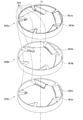
- FIG. 17 is a cross-sectional perspective view of a BB cross section including an axis x in FIG. It is an exploded perspective view which extracted only the spacer and the blade member from the rotating apparatus which concerns on 3rd Embodiment which is an example of this invention. It is a perspective view which extracted only the moving blade from the rotating apparatus which concerns on 3rd Embodiment which is an example of this invention. It is an exploded perspective view which extracted only the moving blade from the rotating apparatus which concerns on 3rd Embodiment which is an example of this invention. It is an enlarged perspective sectional view of the rotating apparatus which concerns on one modification of this invention.
- blower or intake device
- blowing or intake
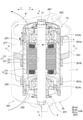
- FIG. 1 is a cross-sectional view of a rotating device 1 according to a first embodiment, which is an example of the present invention
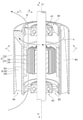
- FIG. 2 is a transmission of a cross section (AA cross section in FIG. 1) including an axis x of the rotating device 1. It is a sectional view.
- the housing 7 is shown in a transparent state by being drawn by an imaginary line (dashed-dotted line).
- the terms "upper” and “lower” mean the vertical relationship in FIGS. 1 and 2, and do not necessarily match the vertical relationship in the direction of gravity. ..
- the arrow a direction is defined as the upper side a
- the arrow b direction is defined as the lower side b.
- the direction away from the axis x is defined as the outer peripheral side c
- the direction toward the axis x is the inner circumference.
- the side d is used, and both directions are the radial direction cd. Then, the clockwise direction (circumferential direction seen from the upper side a) around the axis x is the circumferential direction e, and the counterclockwise direction is the circumferential direction f. The same applies to the arrows a to f indicating these directions and x indicating the axis line in the description of the second embodiment described later.
- the portion that rotates in the rotating device 1 is referred to as a "rotating side", and the portion that supports the member on the rotating side and is fixed without rotating itself is referred to as a "fixed side”.
- a rotating side the portion that supports the member on the rotating side and is fixed without rotating itself
- a fixed side Each may be referred to.
- the portion that does not rotate and is fixed by itself is relatively stationary with respect to the rotating portion, the portion that does not rotate and is fixed by itself may be referred to as a stationary portion. The same applies to the description of the second embodiment described later with respect to these names.
- the rotating device 1 of the present embodiment includes a shaft member 5, a rotor 3 which is a tubular rotating body that can rotate with respect to the shaft member 5, a tubular housing 7 surrounding the rotor 3, and a rotor 3 as a shaft member.
- a bearing 4 that rotatably supports the rotor 3, connecting members 81 and 82 that are arranged between the rotor 3 and the bearing 4 and connect the two, a stator 2 inside the rotor 3, and a rotor 3 are provided.
- the stator 2 includes a stator core 21 fixed to the shaft member 5 and having a plurality of magnetic pole portions 23 radially extending to the outer peripheral side with the shaft member 5 as an axis, and a coil 22 wound around the magnetic pole portion 23.
- the illustrated stator 2 is arranged in the housing 7 so that the gap between the first bearing 41 and the stator 2 and the gap between the second bearing 42 and the stator 2 are equal to each other.
- stator core 21 is a laminated body in which magnetic materials such as silicon steel plates are stacked, and the annular portion 24 coaxially arranged so as to surround the shaft member 5 and the annular portion 24 toward the outer peripheral side. It is provided with a plurality of magnetic pole portions 23 formed so as to extend radially in the radial direction.
- the rotor 3 includes a magnet 31 facing the magnetic pole portion 23 on the outer peripheral side of the stator 2 and a cylindrical tubular member 32.
- a magnet 31 is arranged on the inner peripheral surface of the tubular member 32.
- the tubular member 32 has a cylindrical shape centered on the shaft of the shaft member 5, and surrounds the stator 2.
- the tubular member 32 also has a function of preventing leakage of a magnetic field from the inside of the tubular member 32, and is formed of a magnetic material.
- the tubular member 32 may be made of a non-magnetic material such as aluminum or plastic as long as there is no problem in terms of characteristics.
- the magnet 31 is attached to the inner peripheral surface of the tubular member 32 so as to face the stator 2.
- the magnet 31 has an annular shape, and a region magnetized at the N pole and a region magnetized at the S pole are alternately provided along the circumferential direction at regular intervals (or at regular intervals). Has been done.
- the magnet 31 may be an annular integrally molded product, but a plurality of magnets may be arranged side by side on the inner peripheral surface of the tubular member 32 and arranged in a tubular shape.
- the bearing 4 is arranged on both sides of the stator 2 in the axial direction of the shaft member 5, and has two bearings, a first bearing 41 located on the upper side a and a second bearing 42 located on the lower side b. That is, the magnet 31 and the stator 2 are located between the first bearing 41 and the second bearing 42 in the axial direction of the shaft member 5.
- the first bearing 41 and the second bearing 42 use members having the same configuration (same shape, structure, size, and material).
- the first bearing 41 is a so-called ball bearing including an outer ring 41a, an inner ring 41b, and a bearing ball 41c interposed between the outer ring 41a and the inner ring 41b.
- the first bearing 41 is made of, for example, a hard metal such as iron or a member such as ceramics.
- the second bearing 42 as described above.
- a connecting member (hereinafter referred to as "inner impeller”) 81 is arranged between the outer ring 41a of the first bearing 41 and the inner peripheral surface of the end portion of the upper side a of the tubular member 32.
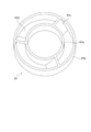
- FIG. 3 shows an enlarged perspective view in which only the inner impeller 81 is extracted.
- the inner impeller 81 includes an inner ring portion (hereinafter referred to as “inner ring portion”) 81a and an outer ring portion (hereinafter referred to as “outer ring portion”) 81b.
- the inner impeller 81 gas can pass between the inner ring portion 81a and the outer ring portion 81b except for the position of the blade 81c. That is, the inner impeller 81 has a ventilation path 81d.
- the inner impeller 81 may be molded from any material such as resin, aluminum, and other various metals, but is preferably molded from resin from the viewpoint of weight reduction, cost reduction, and moldability.
- the plurality of blades 81c are oriented in a direction inclined with respect to the axis x direction (the axial direction of the shaft member 5).
- the three blades 81c are tilted at the same angle. Therefore, the inner impeller 81 functions as a so-called fan that causes a gas flow in the axis x direction by rotating.
- FIG. 4 shows an enlarged perspective view in which only the spacer 82 is extracted.
- the spacer 82 includes an inner ring portion (hereinafter, referred to as an “inner ring portion”) 82a, an outer ring portion (hereinafter, referred to as an “outer ring portion”) 82b, and the spacer 82. It has a plurality of (three in this embodiment) spokes 82c, which are plate-shaped and connect between the inner ring portion 82a and the outer ring portion 82b.
- the spacer 82 In the spacer 82, the space between the inner ring portion 82a and the outer ring portion 82b is a ventilation path 82d through which gas can pass, except for the position of the spoke 82c.
- the spacer 82 may be molded from any material such as resin, aluminum, and other various metals, but is preferably molded from the viewpoint of weight reduction, cost reduction, and moldability.
- the side surface (plate surface) of the plurality of spokes 82c is inclined toward the stator 2 side with respect to the axis x direction. Not.
- the inner peripheral surface of the inner ring portion 81a of the inner impeller 81 is fixed to the outer peripheral surface of the outer ring 41a of the first bearing 41.
- the inner peripheral surface of the inner ring portion 82a of the spacer 82 is fixed to the outer peripheral surface of the outer ring 42a of the second bearing 42.
- the inner peripheral surfaces of the inner ring portions 81a and 82a and the outer peripheral surfaces of the outer rings 41a and 42a are not particularly limited and may be fixed by a conventionally known method. Engagement and the like, or a combination of these plurality of fixing means (fixing elements) can be mentioned.
- FIG. 5 shows an exploded perspective view of the rotating device 1 according to the present embodiment in which only the stator core 21, the bearing 4, the inner impeller 81, and the spacer 82 are extracted.
- the inner ring portion 81a of the inner impeller 81 is fixed to the outer ring 41a of the first bearing 41. Further, the inner ring portion 82a of the spacer 82 is fixed to the outer ring 42a of the second bearing 42.
- stator core 21 in which the coil 22 is not shown is drawn, but in reality, the stator 2 in which the coil 22 is wound around the magnetic pole portion 23 of the stator core 21 is prepared.
- the set of the first bearing 41 and the inner impeller 81, the stator 2, and the second bearing 42 and the spacer 82 are arranged in this order, and the shaft member 5 is inserted and fitted into the central shaft x.
- the inner ring 41b of the first bearing 41 and the inner ring 42b of the second bearing 42 are gap-fitted to the shaft member 5 and then fixed with an adhesive. Therefore, the adhesive is filled in the gap between the inner ring 41b and the shaft member 5 and between the inner ring 42b and the shaft member 5.
- the inner ring 41b of the first bearing 41 and the inner ring 42b of the second bearing 42 may be press-fitted into the shaft member 5 and fixed.
- the inner ring 41b of the first bearing 41 and the inner ring 42b of the second bearing are fixed to the shaft member 5 and become a stationary portion together with the shaft member 5.
- the shaft member 5 and the housing 7 are members that are (relatively) stationary with respect to the rotor 3. Therefore, these are collectively referred to as a stationary member (resting portion).
- the outer peripheral surface of the outer ring portion 81b of the inner impeller 81 is fixed to the inner peripheral surface of the end portion of the upper side a of the tubular member 32. Further, the outer peripheral surface of the outer ring portion 82b of the spacer 82 is fixed to the inner peripheral surface of the end portion of the lower side b of the tubular member 32.
- the outer peripheral surface of the outer ring portions 81b and 82b and the inner peripheral surface of the tubular member 32 are not particularly limited, and may be fixed by a conventionally known method, for example, press-fitting, tightening, fixing with an adhesive, and engaging. Etc., or a combination of these plurality of fixing means (fixing elements) can be mentioned.
- the inner ring 41b of the first bearing 41 and the inner ring 42b of the second bearing 42 are fixed to the outer peripheral surface of the shaft member 5, and the outer ring 41a of the first bearing 41 and the outer ring 42a of the second bearing 42 are inner impellers. It is fixed to the inner peripheral surfaces of both ends of the tubular member 32 via the 81 and the spacer 82.
- the rotor 3 is configured to be rotatable around the axis x of the shaft member 5.
- the shaft member 5 is made of, for example, aluminum for weight reduction, and is in a hollow state (more specifically, a cylindrical state).
- the shaft member 5 is a member on the fixed side. Since the member has a function of supporting the stator 2, the rotor 3, the bearing 4, and the moving blade 6 with respect to the housing 7, rigidity corresponding to the function is required.
- the tubular member 32 has the first bearing 41 and the second bearing 42, and the inner impeller 81 and the spacer 82 at both ends thereof, so that the internal space is isolated. It has become. Power must be supplied to the coil 22 of the stator 2 in the isolated internal space of the tubular member 32.
- isolated here refers to a state in which there is seemingly no place where a lead wire for supplying power can be wired from the outside to the inside.
- the inside space of the isolated tubular member 32 and the outside thereof are electrically connected by passing a lead wire through the cavity inside the shaft member 5. Therefore, the lead wire can supply power to the coil 22 of the stator 2 in the internal space of the tubular member 32.
- stator 2 rotor 3, bearing 4, inner impeller 81, spacer 82, and shaft member 5
- the rotor 3 surrounding the stator 2 is rotatable with respect to the stator 2 fixed to the shaft member 5, and constitutes a so-called outer rotor type brushless motor.
- outer rotor type brushless motor a shaft member fixed to the rotor rotates and a rotational force is taken out by the shaft member.
- the shaft member 5 is used. Is a member on the fixed side, and is configured so that the rotational force is directly taken out from the rotor 3.
- the housing 7 is a member having a cylindrical shape, and is made of, for example, plastic or metal. Although not shown, both ends of the housing 7 in the axial direction are openings (hereinafter, the opening on the upper side a is referred to as an "upper end opening” and the opening on the lower side b is referred to as a "lower end opening”). ing.
- a part of the components of the rotating device 1 is housed inside the housing 7, and the shaft member 5 is fixed to the upper end portion and the lower end portion of the housing 7.
- the upper end portion and the lower end portion of the housing 7 each have three spoke portions 71a connected to the tubular main body portion (cylindrical portion 72) of the housing 7, and a disk portion 71b to which the spoke portions 71a are connected.
- the shaft member 5 is fixed to the disk portion 71b.
- the housing 7 and the shaft member 5 form a member on the fixed side.
- an upper end opening 75 and a lower end opening 76 are provided at the upper end and the lower end of the housing 7, and the upper end opening 75 and the lower end opening 76 surround the disk portion 71b and the shaft member 5, respectively. ..
- FIG. 6 is a perspective view of the moving blade 6 extracted from the rotating device 1 according to the present embodiment
- FIG. 7 is a perspective view of the moving blade 6 as viewed from the upper side a in the axial direction.
- the rotor blades 6 are arranged between the inner cylinder 61 attached to the outer peripheral surface of the cylinder member 32, the outer cylinder 63 facing away from the inner peripheral surface of the housing 7, and the inner cylinder 61 and the outer cylinder 63.
- a plurality of blades 62 (five in this embodiment) are provided.
- a cavity 64 is formed between the inner cylinder 61 and the outer cylinder 63, and the blades 62 arranged in the cavity are in a state of connecting the inner cylinder 61 and the outer cylinder 63. Therefore, the inner cylinder 61, the blade 62, and the outer cylinder 63 form an integral blade 6.
- the blade 62 faces in a direction inclined with respect to the axis x direction of the shaft member 5.
- the five blades 62 are arranged at equal intervals in the circumferential direction ef and are inclined at the same angle.
- the rotor blade 6 has an outer peripheral surface of the cylinder member 32 by inserting the cylinder member 32 of the rotor 3 into the inner peripheral portion (inner hole) of the inner cylinder 61 and fixing the rotor blade 6 at a predetermined position with an adhesive or the like. It is attached to. Therefore, as the rotor 3 rotates, the rotor blade 6 rotates in the housing 7.
- the moving blade 6 Since the moving blade 6 is adapted to rotate with the rotation of the rotor 3, it rotates together with the rotor 3, and a gas flow in the axis x direction is generated according to the rotation of the moving blade 6. This air flow is generated in the cavity 64 between the inner cylinder 61 and the outer cylinder 63 toward either the upward direction or the downward direction in the axial direction of the shaft member 5.
- the rotating device 1 of the present embodiment by driving the rotating device 1 to rotate the rotor blade 6 in the clockwise direction e, the air taken in from the lower end opening 76 passes through the cavity 64 and is the upper end. It is configured to blow out from the opening 75.
- the rotating device 1 has a rotor blade 6 provided on the outer peripheral surface of the rotor 3 which is a rotating body, and a cylindrical housing 7 is provided so as to surround the moving blade 6 so that both ends of the housing 7 are opened.
- One of the portions is used as an intake port and the other is used as a discharge port, and a rotating mechanism (a part of a plurality of components of the rotating device 1) for rotating the moving blade 6 and the moving blade 6 can be housed in the internal space of the housing 7. is made of.
- one of the inner impeller 81 and the spacer 82 can be used as a suction port and the other can be used as a discharge port.
- air passage sometimes referred to as "air passage”
- the space communicating from the upper end opening 75 to the lower end opening 76 is hollow so that the air flow is not obstructed by members other than the spoke portion 71a. Further, since the space is a straight tube except for the space occupied by the cylindrical motor, air flows straight. Therefore, by rotating the rotor blade 6, air can be sent straight from the upper end opening toward the lower end opening. Therefore, according to the rotating device 1 according to the present embodiment, air can be efficiently sent out, and a strong wind and a large air volume (large suction amount) can be supplied.
- the rotating device 1 since the first bearing 41 and the second bearing 42 are fixed to both ends of the rotor 3 and the rotor 3 to be a rotating body is supported, the rotor 3 is supported by the shaft member 5. On the other hand, the rotation of the rotor 3 is stable.
- the first bearing 41 and the second bearing 42 which are constituent members of the rotor 3 which is a rotating body and have a predetermined weight, rotatably support the rotor 3 in the axial direction of the shaft member 5. Since it is between them, the balance in the axial direction is good and the rotation of the rotor 3 is stabilized.
- the position of the bearing is more preferably at both ends of the rotating body as in the present embodiment, but if it is near both ends of the rotating body, the rotation of the rotating body with respect to the shaft member is sufficiently stable. become.
- the "neighborhood” referred to here may be a position between both ends and the center of the rotating body and close to both ends of the rotating body, and cannot be clearly defined numerically.
- the rotating body A region 20% long from both ends in the axial direction, preferably 10% long from both ends, is included in the concept of "near both ends".
- the rotating device 1 since the first bearing 41 and the second bearing 42 have the same configuration, the rotation including the outer rings 41a and 42a and the rotor 3 which are a part of the bearing 4 The axial balance of the part is improved. That is, in the rotating device 1 according to the present embodiment, the balance in the axial direction of the rotating device 1 as a whole becomes good, so that the rotation of the rotor 3 is stabilized from this viewpoint as well.
- the rotating device 1 according to the present embodiment can realize miniaturization of the entire device, is less likely to cause fluctuation in the rotation of the rotor 3, and can achieve high-precision stabilization. Further, since stabilizing the rotation of the rotor 3 means that rotation unevenness is less likely to occur, it is possible to realize high rotation and high torque of the rotating device 1. That is, according to the rotating device 1 according to the present embodiment, it is possible to provide a rotating device having excellent characteristics as a rotating device while realizing miniaturization.
- the upper and lower ends of the shaft member 5 are fixed to the housing 7 as an example, but the fixed side shaft member 5 may be fixed to the housing 7 in some way. At least one end or a part of the shaft member 5 may be fixed to the housing.
- the rotating device 1 of the present embodiment can realize high performance in a small size, but because of its high performance, for example, due to high speed rotation, the coil 22 and the stator core 21 have a higher temperature. It becomes easy to become. Therefore, it is required to cool the stator 2 including the heat generation source such as the coil 22 and the stator core 21, but it is difficult to secure sufficient cooling performance only by providing the vent for that purpose in the tubular member 32. There are cases. In addition, it is difficult to secure a place to provide a vent. If the tubular member 32 is intentionally provided with a vent for cooling the stator 2, it is necessary to secure a place for providing the vent, which may hinder the miniaturization of the rotating device 1.
- the stator 2 is provided by arranging a connecting member (inner impeller 81 and spacer 82) having a ventilation path for communicating the inside and outside of the rotor 3 between the bearing 4 and the rotor 3. It realizes efficient cooling.
- FIG. 8 shows an explanatory diagram illustrating a flow of a gas for cooling the inside of the rotor 3 in the rotating device 1 according to the present embodiment. In FIG. 8, the housing 7 is omitted.
- the inner impeller 81 is rotated by the rotation of the rotor 3 in the arrow h direction (clockwise e direction) in FIG. 8, and the blade 81c strengthens the air flow in the upper a direction in the cavity 64.
- a strong air flow is generated in the direction of the arrow g in FIG. 8, and the air flow efficiently cools the stator 2 including the heat generating source such as the coil 22 and the stator core 21 in the tubular member 32 of the rotor 3.
- the connecting member of the upper end opening 75 on the gas discharge port side is the inner impeller 81 having the blade 81c, a large amount of gas can be taken into the inside of the rotor 3 and discharged. Therefore, according to the rotating device 1 of the present embodiment, the heat generation source such as the coil 22 and the stator core 21 can be cooled extremely efficiently.
- the connecting member inner impeller 81 and spacer 82
- the connecting member having a ventilation path communicating the inside and outside of the rotor 3
- gas is taken in and discharged. It is not necessary to provide a vent for the cylinder member 32. That is, since the connecting member having a ventilation path can be arranged without increasing the length in the axis x direction, the rotating device 1 can be miniaturized.
- the length in the axis x direction has to be extended, and the length of the entire rotating device in the axial direction becomes long.
- the length of the entire rotating device in the axial direction is increased. It can prevent it from becoming long.
- the connecting member on the upper side a which is the gas discharge port side
- the lower side b which is the gas intake side
- the connecting member may be an inner impeller having blades 81c, or the connecting member on the upper side a on the discharge port side may be replaced with a spacer and the connecting member on the lower side b on the intake side may be replaced with an inner impeller. ..
- the inner impeller 81 having the blades 81c is provided as the connecting member as in the present embodiment, gas may be passed through the connecting member to the stator 2 inside the rotor 3 to cool the stator 2.
- the amount of air discharged from the rotating device 1 can be increased.
- the rotor blade 6 is arranged between the inner cylinder 61, the outer cylinder 63, and the inner cylinder 61 and the outer cylinder 63 attached to the outer peripheral surface of the cylinder member 32, and connects between the inner cylinder 61 and the outer cylinder 63.
- a plurality of blades 62 are provided. Since the moving blade includes an outer cylinder 63 that surrounds the plurality of blades 62, it is possible to efficiently blow gas from the rotating device 1. Therefore, even if the housing 7 for accommodating the moving blades 6 is not provided, gas can be blown.
- FIG. 9 is a transmission cross-sectional view of a cross section including the axis x of the rotating device 201 according to the second embodiment.
- the rotary device 201 according to the second embodiment is different from the rotary device 1 according to the first embodiment in the configuration around the upper and lower bearings and the structure of the moving blades.
- a connecting member (hereinafter referred to as “spacer”) 281 is arranged between the outer ring 41a of the first bearing 41 and the inner peripheral surface of the end portion of the upper end a of the tubular member 32, and the second bearing 42 has a connecting member (hereinafter referred to as “spacer”) 281.
- a connecting member (hereinafter referred to as “spacer”) 282 is also arranged between the outer ring 42a and the inner peripheral surface of the end portion of the lower side b of the tubular member 32. These spacers 281,282 have the same shape as the spacer 82 in the first embodiment.
- the rotating device 201 includes a blade member 291 having a plurality of blades (reference numeral 291b described later) adjacent to the outside (upper side a) of the spacer 281 in the axis x direction. Further, the rotating device 201 according to the present embodiment includes a blade member 292 having a plurality of blades (reference numeral 292b described later) adjacent to the outside (lower side b) of the spacer 282 in the axis x direction.
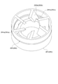
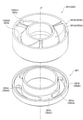
- FIG. 10 shows an enlarged perspective view in which only the blade member 291 on the upper side a in FIG. 9 is extracted from the rotating device 201.
- the blade member 291 includes a ring portion 291a, a plurality of blades 291b extending in the central axial direction from the ring portion 291a (six in the present embodiment), and a ring of each of the blades 291b. It has a protruding portion 291c that protrudes downward from the connecting portion side with the portion 291a.
- FIG. 11 shows an enlarged perspective view in which only the blade member 292 on the lower side b in FIG. 9 is extracted from the rotating device 201.
- the blade member 292 includes a ring portion 292a, a plurality of blades 292b extending in the central axial direction from the ring portion 292a (six in the present embodiment), and a ring of each of the blades 292b. It has a protruding portion 292c that protrudes downward from the connecting portion side with the portion 292a.
- the blade members 291,292 may be molded from any material such as resin, aluminum, and other various metals, but are preferably molded from resin from the viewpoint of weight reduction, cost reduction, and moldability.
- the plurality of blades 291b and 292b are oriented in a direction inclined with respect to the axis x direction (the axial direction of the shaft member 5).
- the six blades 291b and 292b are inclined at the same angle. Therefore, the blade members 291,292 function as a so-called fan that causes a gas flow in the axis x direction by rotating.
- FIG. 12 shows an enlarged perspective view in which only the spacer 281 and the blade member 291 on the upper side a in FIG. 9 are extracted from the rotating device 201.
- the spacer 282 and the blade member 292 on the lower side b in FIG. 9 are also inverted upside down and have the same shape and structure. Therefore, in FIG. 12, the spacer 282 and the blade member 292 are also designated in parentheses. Keep it.
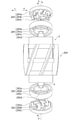
- FIG. 13 shows an exploded perspective view of the rotating device 201 according to the present embodiment.
- the housing 7 is not shown.
- the blade members 291,292 are superposed on the spacers 281,282 so that the protrusions 291c and 292c sides face the spacers 281,282.
- the spacers 281,282 include inner ring portions (hereinafter referred to as “inner ring portions”) 281a and 282a, outer ring portions (hereinafter referred to as “outer ring portions”) 281b and 282b, and inner rings. It has a plurality of (three in this embodiment) spokes 281c and 282c in a plate shape connecting the portions 281a and 282a and the outer ring portions 281b and 282b.
- the spacers 281,282 have a simple perforated shape in order to secure the accuracy and strength as a connecting member easily and at low cost.
- the inner peripheral surface of the inner ring portion 281a of the spacer 281 is fixed to the outer peripheral surface of the outer ring 41a of the first bearing 41. Further, the inner peripheral surface of the inner ring portion 282a of the spacer 282 is fixed to the outer peripheral surface of the outer ring 42a of the second bearing 42.
- the inner peripheral surfaces of the inner ring portions 281a and 282a and the outer peripheral surfaces of the outer rings 41a and 42a are not particularly limited and may be fixed by a conventionally known method. Engagement and the like, or a combination of these plurality of fixing means (fixing elements) can be mentioned.
- outer peripheral surfaces of the outer ring portions 281b and 282b of the spacers 281,282 are fixed to the inner peripheral surfaces of the ends of the upper and lower side abs of the tubular member 32 in the axial x direction.
- the outer peripheral surface of the outer ring portions 281b and 282b and the inner peripheral surface of the tubular member 32 are not particularly limited, and may be fixed by a conventionally known method, for example, press-fitting, tightening, fixing with an adhesive, and engaging. Etc., or a combination of these plurality of fixing means (fixing elements) can be mentioned.
- the spokes 281c and 282c are connected to the inner ring portions 281a and 282a and the outer ring portions 281b and 282b at substantially the center in the thickness direction (axis x direction) of the spacers 281,282.
- the positions of the spokes 281c and 282c are inside the end faces of the inner ring portions 281a and 282a and the outer ring portions 281b and 282b on the stator 2 side.
- the spokes 281c and 282c, the inner ring portions 281a and 282a, and the outer ring portions 281b and 282b form a stepped portion recessed in the axis x direction.
- the protruding portions 291c and 292c of the blade members 291,292 are fitted to the penetrating portions and the stepped portions of the spacers 281,282 and are integrated as shown in FIG.
- a leaf spring 250 is attached near the end of the upper side a of the shaft member 5 to urge the blade member 291 and the bearing 41 from the upper side a.
- the blade member 291 and the spacer 281 are stably integrated by the urging force of the leaf spring 250.
- a leaf spring 251 is attached near the end of the lower side b of the shaft member 5 to urge the blade member 292 and the bearing 42 from the lower side b.
- the blade member 292 and the spacer 282 are stably integrated by the urging force of the leaf spring 251.
- the spacers 281,282 are fixed to the inner peripheral surface of the tubular member 32 of the rotor 3. Therefore, the blade members 291,292 fixed to the cylinder member 32 of the rotor 3 via the spacers 281,282 are rotated along with the rotation of the rotor 3.
- FIG. 14 is a perspective view obtained by removing only the housing 7 from the rotating device 201 according to the present embodiment.
- the rotor blade 206 is attached to the outer peripheral surface of the tubular member 32 of the rotor 3 over a length of about 70% in the axial direction (axis x direction) of the tubular member 32.
- the rotor blade 206 bridges three annular fixing portions 261a, 261b, 261c attached to the outer peripheral surface of the tubular member 32 and arranged at equal intervals in the axis x direction, and these three fixing portions 261a, 261b, 261c.
- a plurality of blades 262 (six in this embodiment) fixed obliquely with respect to the axis x direction are provided.
- the blade 262 faces in a direction inclined with respect to the axis x direction of the shaft member 5.
- the six blades 262 are arranged at equal intervals in the circumferential direction ef and are inclined at the same angle.
- the rotor blade 206 is fitted by inserting the tubular member 32 of the rotor 3 into the rings of the three fixing portions 261a, 261b, and 261c, and fixing the rotor blade 206 at a predetermined position with an adhesive or the like to form an outer peripheral surface of the tubular member 32. It is attached to. Therefore, as the rotor 3 rotates, the rotor blade 206 rotates in the housing 7.
- the rotor blade 206 Since the rotor blade 206 is adapted to rotate with the rotation of the rotor 3, it rotates together with the rotor 3, and a gas flow in the axis x direction is generated according to the rotation of the rotor blade 206. This air flow occurs in the cavity 277 between the rotor 3 and the housing 7 in either the axially upward or downward direction of the shaft member 5.
- the gas taken in from the lower end opening 76 passes through the cavity 277 and is the upper end. It is configured to blow out from the opening 75.
- the rotating device 201 according to the present embodiment is similar to the first embodiment, in that the entire rotating device is downsized, a strong wind and a large air volume (large suction amount) are supplied, the rotation of the rotor 3 is stabilized, the rotation speed is increased, and the rotation speed is increased. It is possible to realize torque reduction, and it is possible to provide a device having excellent characteristics as a rotating device.
- FIG. 15 shows an explanatory diagram illustrating a flow of gas for cooling the inside of the rotor 3 in the rotating device 201 according to the present embodiment.
- the blade members 291,292 are rotated by the rotation of the rotor 3 in the arrow h direction (clockwise e direction) in FIG. 15, and the blades 291b and 292b strengthen the airflow toward the upper side a in the tubular member 32. Will be done.
- a strong air flow is generated in the direction of the arrow g in FIG. 15, and the air flow efficiently cools the stator 2 including the heat generating source such as the coil 22 and the stator core 21 in the tubular member 32 of the rotor 3.
- the blade members 291,292 having blades 291b and 292b are provided on both sides of the upper end opening 75 and the lower end opening 76, a large amount of gas can be taken into the rotor 3 and discharged. Therefore, according to the rotating device 201 of the present embodiment, the heat generation source such as the coil 22 and the stator core 21 can be cooled extremely efficiently.
- the airflow path from the spacer 282 to the spacer 281 includes a coil 22, a stator core 21, and a magnet 31, and other than these cooling targets, there are obstacles to the airflow. Since there is no gas, the gas is efficiently supplied to these cooling targets. Further, the gas flows along the axial direction x except that it comes into contact with these cooling objects. Therefore, according to the rotating device 201 according to the present embodiment, the cooling gas can be efficiently supplied to the cooling target.
- the connecting member spacer 281,282 having a ventilation path communicating the inside and outside of the rotor 3 is arranged between the bearing 4 and the rotor 3, the gas is taken in and discharged. It is not necessary to provide the vent port of the above to the tubular member 32. That is, since the connecting member having the ventilation path can be arranged without increasing the length in the axis x direction, the rotating device 201 can be miniaturized.
- the cooling gas intake blade member 292 and spacer 282
- the discharge port spacer 281 and blade member 291
- the blade members 291,292 having the blades 291b and 292b are provided adjacent to both of the two connecting members (spacers 281,282), but the discharge port side and the discharge port side.
- a blade member having blades may be provided on the discharge port side to improve the amount of air blown from the rotating device or to improve the wind pressure.
- the rotor blade 206 includes the annular fixing portions 261a, 261b, and 261c, the region (area) in contact with the rotor (rotating body) 3 can be reduced, and as a result, the gas on the outer peripheral side surface of the rotor 3 can be reduced. Since the exposed area (area) can be increased, the heat dissipation of the rotor 3 can be improved.
- the connecting member (spacers 281,282) and the blade members 291,292 that generate an air flow in the cylinder member 32 are separated. ing. Therefore, in the present embodiment, the degree of freedom of the shape as the connecting member is high, and the cross-sectional area of the ventilation path in the connecting member can be expanded as compared with the case of the first embodiment, and the connecting member can be used as a connecting member. It is possible to improve the strength of the. Further, since the degree of freedom in the shape of the connecting member is high, the size restriction on the bearing 4 side is greatly reduced.
- rotating equipment can be assembled without blade members and can be shaped in that state, for example, prepare multiple types of blade members with different shapes, sizes, thicknesses, etc., according to the application and purpose. , You can choose from these each time.
- mass-producing rotating equipment without blade members and combining it with blade members according to the application and purpose, it is possible to meet a wide range of needs and it is extremely cost effective. It will be advantageous.
- FIG. 16 is a transmission cross-sectional view of a cross section including the axis x of the rotating device 301 according to the third embodiment.
- the rotary device 301 according to the third embodiment has a configuration around the upper and lower bearings and a structure of the moving blades, which is different from the rotary device 1 according to the first embodiment and the rotary device 201 according to the second embodiment. It's different.
- the members or parts having the same functions and structures as those of the first embodiment and the second embodiment are designated by the same reference numerals as those of the first embodiment or the second embodiment.
- a detailed description of each drawing relating to the form will be omitted (however, this does not apply if a specific description is added).
- a connecting member (hereinafter referred to as “spacer”) 381 is arranged between the outer ring 41a of the first bearing 41 and the inner peripheral surface of the end portion of the upper side a of the tubular member 32, and the second bearing 42 has a connecting member (hereinafter referred to as “spacer”) 381.
- a connecting member (hereinafter referred to as “spacer”) 382 is also arranged between the outer ring 42a and the inner peripheral surface of the end portion of the lower side b of the tubular member 32.
- the rotating device 301 includes a blade member 391 having a plurality of blades (reference numeral 391c described later) adjacent to the outside (upper side a) of the spacer 381 in the axis x direction. Further, the rotating device 301 according to the present embodiment includes a blade member 392 having a plurality of blades (reference numeral 392c described later) adjacent to the outside (lower side b) of the spacer 382 in the axis x direction.
- FIG. 17 shows an enlarged perspective view in which only the spacer 381 and the blade member 391 on the upper side a in FIG. 16 are extracted from the rotating device 301.
- FIG. 18 shows a cross-sectional perspective view of the BB cross section including the axis x in FIG.
- FIG. 19 shows an exploded perspective view of the spacer 381 and the blade member 391.
- FIGS. 17 to 19 reference numerals are given in parentheses as the spacer 382 and the blade member 392.
- the spacer 381 and the blade member 391 on the upper side a will be mainly described, but the same applies to the spacer 382 and the blade member 392 on the lower side a.
- the blade member 391 is referred to as an inner ring portion (hereinafter referred to as “inner ring portion”) 391a and an outer ring portion (hereinafter referred to as “outer ring portion”). ) 391b, and a plurality of (three in this embodiment) blades 391c in a helical shape connecting between the inner ring portion 391a and the outer ring portion 391b. Since the ring portions (inner ring portion 391a and outer ring portion 391b) are provided on both the inner peripheral side and the outer peripheral side, the blade 391c is reinforced and the strength of the blade member 391 is improved.
- the blade members 391 and 392 may be molded from any material such as resin, aluminum, and other various metals, but are preferably molded from resin from the viewpoint of weight reduction, cost reduction, and moldability. As shown in FIGS. 17 to 19, the three blades 391c are oriented in a direction inclined with respect to the axis x direction (the axial direction of the shaft member 5). The three blades 391c are inclined at the same angle to form a helical shape. A cavity 391d is formed between the three blades 391c.
- the inner ring portion 391a has an inclined surface whose cross-sectional shape extends from the upper side a to the lower side b, and includes a conical cylinder portion 391e having a wall thickness at the lower side. Further, the inner ring portion 391a is a cylindrical protruding portion (hereinafter referred to as “cylindrical protruding portion”) 391f extending from the outermost circumference of the conical cylinder portion 391e to the lower side b at the bottom portion 391 g of the conical cylinder portion 391e. Have.
- the outer ring portion 391b has an inclined surface whose cross-sectional shape slightly expands from the upper side a to the lower side b, and has a conical cylinder portion 391i which is slightly thicker at the lower side and a lower portion.
- the outer peripheral corner of the end of the side b is notched and recessed (the notched portion is referred to as a "notch 391k” as a recess), and a cylindrical protrusion extending from the inner peripheral side to the lower side b. It has a portion (hereinafter referred to as a “cylindrical protrusion”) 391h.
- the lengths of the cylindrical protrusion 391f and the cylindrical protrusion 391h are longer in the cylindrical protrusion 391f, and the end portion (lower end) of the lower side b is at the same position.
- the spacer 381 has an annular base 381c facing the three blades 391c of the blade member 391, and a tubular ring portion (hereinafter, "inner ring”) that is connected to the inner peripheral side of the base 381c and extends in the vertical direction ab of the axis x. It has a 381a and a tubular ring portion (hereinafter, referred to as an “outer ring portion”) 381b which is connected to the outer peripheral side of the base 381c and extends in the vertical direction ab of the axis x. In the axis x direction, the inner ring portion 381a is longer than the outer ring portion 381b.
- the spacers 381 and 382 have a simple perforated shape in order to secure the accuracy and strength as a connecting member easily and at low cost.
- the inner peripheral surface of the inner ring portion 381a of the spacer 381 is fixed to the outer peripheral surface of the outer ring 41a of the first bearing 41. Further, the inner peripheral surface of the inner ring portion 382a of the spacer 382 is fixed to the outer peripheral surface of the outer ring 42a of the second bearing 42.
- the inner peripheral surfaces of the inner ring portions 381a and 382a and the outer peripheral surfaces of the outer rings 41a and 42a are not particularly limited and may be fixed by a conventionally known method. Engagement and the like, or a combination of these plurality of fixing means (fixing elements) can be mentioned.
- outer peripheral surfaces of the outer ring portions 381b and 382b of the spacers 381 and 382 are fixed to the inner peripheral surfaces of the ends of the upper and lower side abs of the tubular member 32 in the axis x direction.
- the outer peripheral surface of the outer ring portions 381b and 382b and the inner peripheral surface of the tubular member 32 are not particularly limited, and may be fixed by a conventionally known method, for example, press-fitting, tightening, fixing with an adhesive, and engaging. Etc., or a combination of these plurality of fixing means (fixing elements) can be mentioned.
- the base 381c is formed with three elliptical holes 381d in which an arc is drawn.
- the hole 381d is a ventilation path through which gas can pass.
- the base 381c is connected to the inner ring portion 381a and the outer ring portion 381b slightly below b in the thickness direction (axis x direction) of the spacers 381 and 382. Therefore, in the spacer 381, the position of the base 381c is inside the end faces of the inner ring portion 381a and the outer ring portion 381b on the stator 2 side.
- the base 381c, the inner ring portion 381a, and the outer ring portion 381b form a stepped portion recessed in the axis x direction.
- the cylindrical protrusion 391f and the cylindrical protrusion 391h of the blade member 391 are fitted to the stepped portion of the spacer 381 and integrated as shown in FIG. That is, the lower ends of the cylindrical protrusion 391f and the cylindrical protrusion 391h are in contact with the surface of the upper side a of the base 381c, the upper end of the inner ring portion 381a is in contact with the bottom 391g of the conical cylinder portion 391e, and the upper end of the outer ring portion 381b. Is in contact with the notch 391k of the conical cylinder portion 391e, and the blade member 391 and the spacer 381 are fitted and integrated.
- the cavity 391d in the blade member 391 integrated with the spacer 381 is connected to the hole 381d corresponding to the ventilation path of the spacer 381 to form the ventilation path of the blade member 391. That is, the gas flow in the cavity 391d indicated by the double-headed arrow k in FIGS. 17 and 18 is connected to the gas flow in the hole 381d indicated by the double-headed arrow m in FIG. It will be a ventilation path that communicates inside and outside.
- a leaf spring 250 is attached near the end of the upper side a of the shaft member 5 to urge the blade member 391 and the bearing 41 from the upper side a.
- the blade member 391 and the spacer 381 are stably integrated by the urging force of the leaf spring 250.
- a leaf spring 251 is attached near the end of the lower side b of the shaft member 5 to urge the blade member 392 and the bearing 42 from the lower side b.
- the blade member 392 and the spacer 382 are stably integrated by the urging force of the leaf spring 251.
- the spacers 381 and 382 are fixed to the inner peripheral surface of the tubular member 32 of the rotor 3. Therefore, the blade members 391 and 392 fixed to the tubular member 32 of the rotor 3 via the spacers 381 and 382 are rotated along with the rotation of the rotor 3.
- FIG. 20 is a perspective view of the moving blade 306 extracted from the rotating device 301 according to the present embodiment.
- FIG. 21 is an exploded perspective view of the moving blade 306.
- the rotor blade 306 is attached to the central region of the tubular member 32 in the axial direction (axis x direction) on the outer peripheral surface of the tubular member 32 of the rotor 3.
- the rotor blade 306 includes a cylindrical cylinder 363 and a plurality of blades 362 (five in this embodiment) obliquely fixed to the inner peripheral surface of the cylinder 363.
- the blade 362 faces in a direction inclined with respect to the axis x direction of the shaft member 5.
- the five blades 362 are arranged at equal intervals in the circumferential direction ef and are inclined at the same angle to form a helical shape.
- the moving blade 306 is formed by stacking three moving blade members 306a, 306b, 306c side by side in the axis x direction.
- the rotor blade members 306a, 306b, 306c each include a tubular portion 363a, 363b, 363c, and five blade portions 362a, 362b, 362c protruding inward from the inner surface thereof. These five blade portions 362a, 362b, 362c are formed on the inner surface as ribs extending toward the axis x-ray.
- the cylinder portions 363a, 363b, 363c are connected side by side in the axis x direction to form one cylinder 363.
- the respective five blade portions 362a, 362b, 362c are arranged side by side in the axis x direction to form five blades 362. ..
- each end of the blade portions 362a, 362b, 362c faces the end of the other blade portions.
- the end of the upper side a of the blade portion 362b faces the end of the lower side b of the blade portion 362a
- the end of the lower side b of the blade portion 362b is the blade portion 362c. It faces the end of the upper side a of.
- any or all of the facing ends of the blades 362a, 362b, 362c and the facing upper and lower ends of the cylinders 363a, 363b, 363c are fixed by means of fixing (fixing) such as an adhesive.
- fixing fixing
- the fixing means (fixing element) is not limited to fixing with an adhesive, and various fixing means (fixing elements) can be appropriately adopted.
- One blade 362 and a blade 362 adjacent to this one blade 362 face each other for each of the five blades 362 of the rotor blade 306 in the axial direction (axis x direction) or the circumferential direction ef of the rotor 3. ..
- each end of each of the five blades 362 of the rotor blade 306 is located between both ends of the blade 362 next to the blade 362.
- the lower end 362-1g of the blade 362-1 has both ends of the adjacent blades 362-2 in the axis x direction or the clockwise circumferential direction e of the blade 362-1. It is located between parts 362-2p and 362-2g.
- the upper end 362-3p of the blade 362-3 is adjacent to the blade 362-2 in the axis x direction or the counterclockwise circumferential direction f of the blade 362-3. It is located between both ends 362-2p and 362-2g of 2.
- each end of each of the five blades 362 of the rotor blade 306 faces a part (side surface) between both ends of the blade 362 adjacent to the blade 362.
- a part of the five blades 362 of the rotor blade 306 overlap each other in the axis x direction. Therefore, the gas passes through the passage formed between the side surfaces of the two adjacent blades 362 in the axis x direction or the circumferential direction ef.
- the rotor blade 306 is divided into three rotor blade members 306a, 306b, 306c. Therefore, the individual blade members 306a, 306b, and 306c have good moldability and can be easily molded even with a general mold. Therefore, by superimposing these rotor blade members 306a, 306b, 306c, the rotor blade 306 having a relatively complicated shape can be formed easily or at low cost.
- alignment grooves 364 are provided at intervals of a central angle of 36 °, and half of them are the inner circumference of the upper side a. It is provided so as to coincide with the place where the blade portions 362a, 362b, and 362c are located on the side.
- the positioning grooves 364 are aligned so that the locations where the blade portions 362a, 362b, 362c are present and the locations where the blade portions 362a, 362b, 362c are not present are alternately arranged on the inner peripheral side of the upper side a, and the three blade members 306a, 306b, 306c are formed. By overlapping, the blade portions 362a, 362b, 362c are connected to form a helical blade 362.
- the rotor blade 306 is attached to the outer peripheral surface of the tubular member 32 by fixing the end portion of the five blades 362 on the axial axis x side in the radial direction to a predetermined position of the tubular member 32 of the rotor 3 with an adhesive or the like. Has been done. Therefore, as the rotor 3 rotates, the rotor blade 306 rotates in the housing 7.
- the rotor blade 306 Since the rotor blade 306 is adapted to rotate with the rotation of the rotor 3, it rotates together with the rotor 3, and a gas flow in the axis x direction is generated according to the rotation of the rotor blade 306. This air flow occurs in the cavity 377 between the rotor 3 and the housing 7 in either the axially upward or downward direction of the shaft member 5.
- the rotating device 301 is capable of downsizing the entire rotating device, supplying a strong wind and a large air volume (large suction amount), and stabilizing the rotation of the rotor 3. It is possible to realize high rotation and high torque, and it is possible to provide a device having excellent characteristics as a rotating device. Further, also in the present embodiment, the stator 2 is efficiently cooled by arranging a connecting member (spacer 381, 382) having a ventilation path for communicating the inside and outside of the rotor 3 between the bearing 4 and the rotor 3. It has realized that.
- the rotation of the rotor 3 in the clockwise e direction or the counterclockwise f direction causes the moving blade 306 to rotate, and the air taken in from the lower end opening 76 or the upper end opening 75 passes through the cavity 377.
- An air flow (direction of arrow i or direction of arrow j) is generated so as to blow out from the upper end opening 75 or the lower end opening 76 (see FIG. 16).
- the blade members 391 and 392 are rotated by the rotation of the rotor 3 in the clockwise e direction or the counterclockwise f direction, and the blades 391c and 392b cause an air flow in the tubular member 32 in the upper a direction or the lower b direction. Is strengthened.
- the stator 2 including the heat generating source such as the coil 22 and the stator core 21 is efficiently cooled by the strong air flow in the tubular member 32 of the rotor 3.
- the blade members 391 and 392 having blades 391c and 392b are provided on both sides of the upper end opening 75 and the lower end opening 76, a large amount of gas can be taken into the rotor 3 and discharged. Therefore, according to the rotating device 301 of the present embodiment, the heat generation source such as the coil 22 and the stator core 21 can be cooled extremely efficiently.
- the blade members 391 and 392 provided up and down have vertically symmetrical helical blades 391c and 392b, the drive of the rotating device 301 is reversed and the rotation direction of the rotor 3 is reversed. , It is possible to generate an air flow in both up and down directions (arrow i direction and arrow j direction).
- the direction of the air flow (downward or upward) due to the rotation of the blade members 391 and 392 that is switched according to the rotation direction of the rotor 3 (clockwise e direction or counterclockwise f direction) is the same as that of the moving blade 306. It is in the same direction as the direction of the air flow due to rotation (clockwise i direction and arrow j direction). Therefore, the total air volume can be improved.
- the second point is that there is no obstacle to the airflow other than the object to be cooled in the path of the airflow in the cylinder member 32, and there is no need to provide a vent for taking in and discharging the gas in the cylinder member 32.
- the heat generation source can be efficiently cooled, and the rotating device 301 can be downsized.
- the rotor blades 306 come into contact with the rotor (rotating body) 3 because the ends of the five blades 362 on the axis x side are in contact with and fixed to the outer peripheral surface of the tubular member 32 of the rotor 3.
- the area (area) can be reduced.
- the region (area) exposed to the gas on the outer peripheral side surface of the rotor 3 can be increased, so that the heat dissipation of the rotor 3 can be improved.
- the connecting members spacers 381 and 382 and the blade members 391 and 392 that generate an air flow in the tubular member 32 are separated. Therefore, in the present embodiment, the degree of freedom in the shape of the connecting member is high, the cross-sectional area of the ventilation path in the connecting member can be expanded, the strength of the connecting member can be improved, and the bearing 4 It is the same as the second embodiment in that the restriction on the size of the side is greatly reduced. Further, the operation and effect of being able to assemble the rotating device without the blade member are the same as those of the second embodiment.
- the rotating device of the present invention has been described above with reference to preferred embodiments, the rotating device of the present invention is not limited to the configuration of the above embodiment.
- one of the connecting members is the inner impeller 81 (first embodiment), and the blade members 291,292 or the blade members are placed on both sides of the upper end opening 75 and the lower end opening 76.
- the examples provided with 391 and 392 are given, even if the configuration is not provided with any blades for generating a cooling air flow in the rotor. I do not care.
- the inner impeller 81 is replaced with the spacer 82, and in the second embodiment and the third embodiment, the blade members 291,292 or the blade members 391, 392 are removed. Even if there is, since it is provided with a connecting member having a ventilation path that communicates inside and outside the rotating body (rotor 3), the action or effect in the present invention can be expected.
- the upper and lower ends of the shaft member 5 are fixed to the housing 7 as an example, but the fixed side shaft member 5 may be fixed to the housing 7 in some way. Therefore, at least one end or a part of the shaft member 5 may be fixed to the housing.
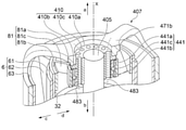
- the rotating device of the present invention is as a modification shown in FIGS. 22 to 24.
- the housing 407 and the shaft members 405, 405', 405 may be fixed via the connecting members 410, 410', 410".
- the connecting members 410, 410', 410 may be made of any material such as resin, aluminum, and other various metals.
- the connecting member 410, 410', 410 includes a cylindrical portion 410a, 410a', 410a" and an annular flange portion 410b, 410b', 410b ".
- the inner peripheral surface of the tubular portions 410a, 410a', 410a is fixed to the outer peripheral surface of the shaft member 405,405', 405" at the end of the upper side a of the shaft member 405,405', 405 ".
- the flange portions 410b, 410b', 410b project from the outer peripheral surface of the tubular portions 410a, 410a', 410a" to the outer peripheral side c.
- the surface of the upper side a of the flange portions 410b, 410b', 410b "exists on the lower side b than the surface of the upper side a of the tubular portions 410a, 410a', 410a".
- the shaft members 405,405', 405 " between the surface of the upper side a of the flange portions 410b, 410b', 410b" and the surface of the upper side a of the tubular portions 410a, 410a', 410a " , There is a part of the tubular portion 410a, 410a', 410a ".
- the inner peripheral surface of the annular portion 471b of the housing 407 comes into contact with the outer peripheral surface of a part of the tubular portions 410a, 410a', 410a ", and the upper surface a of the flange portions 410b, 410b', 410b" and the housing 407.
- the surface of the lower side b of the annular portion 471b is in contact with the connecting member 410, 410', 410 "and the housing 407 is engaged and fixed.
- the tubular portion 410a of the connecting member 410 extends to the end of the lower side b of the first bearing 441 in the axial direction.
- the tubular portion 410a is located between the shaft member 405 and the first bearing 441 in the radial direction.
- the inner ring 441b of the first bearing 441 is fixed to the other part of the tubular portion 410a on the lower side b with respect to the flange portion 410b.
- a plurality of circular through holes 410c penetrating in the axial direction are formed in the tubular portion 410a so as to be arranged in the circumferential direction at equal intervals.
- Each of the plurality of through holes 410c extends from the end of the upper side a of the tubular portion 410a to the end of the lower side b in the axial direction.
- a plurality of (for example, three) lead wires 483 connected to the coil 22 are drawn out of the rotating device through one or more of the through holes 410c. ..
- the surface of the lower side b of the tubular portion 410a'of the connecting member 410'and the surface of the lower side b of the flange portion 410b' form a flat surface.
- the surface of the lower side b of the tubular portion 410a'and the surface of the lower side b of the flange portion 410b' face the surface of the upper side a of the first bearing 41, and the first 1
- the bearing 41 is separated from the upper surface a by a predetermined distance.
- the shaft member 405' is partially or completely hollow in the axial direction and opens to the upper side a.
- the shaft member 405' is provided with a plurality of (for example, three) openings 405a'on the lower side b of the first bearing 41 in the axial direction.
- the number of openings 405a' may be one.
- a plurality of (for example, three) lead wires 483'connected to the coil 22 are drawn into the shaft member 405'from the opening 405a'and the end portion of the shaft member 405'. It is designed to be pulled out from the opening to the outside of the rotating device.
- the surface of the lower side b of the tubular portion 410a "of the connecting member 410" and the surface of the lower side b of the flange portion 410b "form a flat surface.
- the surface of the lower side b of the tubular portion 410a'and the surface of the lower side b of the flange portion 410b' face the surface of the upper side a of the first bearing 41. It is separated from the upper surface a of the first bearing 41 by a predetermined distance.
- a plurality (for example, three) recesses 405a" extending linearly from the end of the upper side a to the lower side b are formed radially and at equal intervals.
- Each recess 405a extendends to the lower side b of the first bearing 41. Note that there may be one recess 405a".
- a plurality of (for example, three) lead wires 483 "connected to the coil 22 are drawn out to the outside of the rotating device through one or more of the recesses 405a". There is.
- the lead wire can be pulled out from the rotating device without difficulty while keeping the number of parts to a minimum.
- the configuration in which the connecting members 410, 410', 410 "are provided at the end of the upper side a of the rotating device is given as an example, but the connecting members 410, 410', 410 "may be provided at the end of the lower side b of the rotating device, or may be provided at both ends.
- the configuration in which the shaft member 405a is open to the upper side a is given as an example, but the shaft member 405'may be open to the lower side b.
- a configuration in which the recess 405a "is formed so as to extend from the end portion of the upper side a of the shaft member 405" to the lower side b in the axial direction is given as an example.
- the configuration in which the inner ring portion 82a and the outer ring portion 82b of the spacer 82 are both cylindrical is given as an example, but the rotating device of the present invention is a modified example shown in FIG. 25.
- the inner ring portion 582a of the spacer 582 may have an annular protruding portion 582aa projecting to the inner peripheral side d at the end portion of the lower side b.
- the outer ring portion 582b of the spacer 582 may have an annular protruding portion 582ba protruding toward the outer peripheral side c at the end portion of the lower side b.
- the protruding portion 582aa engages with the end portion of the lower side b of the inner ring 42b of the second bearing 42 in the axial direction
- the protruding portion 582ba is the end portion of the lower side b of the tubular member 32 in the axial direction. Engage in.
- the protruding portion 582aa and the protruding portion 582ba serve as stoppers, facilitating the positioning of the spacer 582, the rotor 3, and the second bearing 42. Further, it is possible to prevent misalignment due to the spacer 582, the rotor 3 and the second bearing 42 sliding with each other in the axial direction.
- a configuration in which protrusions are provided on the inner peripheral side d and the outer peripheral side c at the end of the lower side b of the connecting member on the lower side b is given as an example.
- protrusions may be provided on the inner peripheral side d and the outer peripheral side c, or both of them may be provided.
- the connecting member having the protrusion may be a spacer or an inner impeller.
- a blower or a suction machine provided with moving blades 6, 206, 306 is given as an example, but the rotating device of the present invention uses the rotational force for a purpose other than the rotation of the moving blades. It doesn't matter.
- the moving blade is not indispensable, and a transmission mechanism such as a gear or a shaft for transmitting the rotational force to the target object is provided, or the target object is directly acted on the rotating body. It should be configured in.
- the rotating device in the above embodiment can be applied to a fluid containing a gas or a liquid.
- those skilled in the art can appropriately modify the rotating device of the present invention according to conventionally known knowledge. As long as the present invention is still provided by such modification, it is, of course, included in the category of the present invention.
- Spacer (connecting member), 381a, 382a ... Inner ring part, 381b, 382b ... Outer ring part, 381c, 382c ... Base, 381d, 382d ... Base, 391 ... Blade member, 391a ... Inner ring part, 391b ... Outer ring part, 391c ... Blade, 391d ... Cavity, 391e ... Conical cylinder part, 391f ... Cylindrical protrusion, 391g ... Bottom, 391h ... Cylindrical protrusion , 391i ... Conical cylinder part, 391k ... Notch, 392 ... Blade member, 392a ... Ring part, 392b ...
Landscapes
- Engineering & Computer Science (AREA)
- Power Engineering (AREA)
- Structures Of Non-Positive Displacement Pumps (AREA)
- Motor Or Generator Cooling System (AREA)
- Connection Of Motors, Electrical Generators, Mechanical Devices, And The Like (AREA)
Priority Applications (5)
| Application Number | Priority Date | Filing Date | Title |
|---|---|---|---|
| CN202180069993.6A CN116325440A (zh) | 2020-08-28 | 2021-08-19 | 旋转设备 |
| JP2022544525A JP7627273B2 (ja) | 2020-08-28 | 2021-08-19 | 回転機器 |
| US18/042,638 US12407222B2 (en) | 2020-08-28 | 2021-08-19 | Rotating machine |
| JP2025010577A JP2025063302A (ja) | 2020-08-28 | 2025-01-24 | 回転機器 |
| US19/300,877 US20250373120A1 (en) | 2020-08-28 | 2025-08-15 | Rotating machine |
Applications Claiming Priority (2)
| Application Number | Priority Date | Filing Date | Title |
|---|---|---|---|
| JP2020-145023 | 2020-08-28 | ||
| JP2020145023 | 2020-08-28 |
Related Child Applications (2)
| Application Number | Title | Priority Date | Filing Date |
|---|---|---|---|
| US18/042,638 A-371-Of-International US12407222B2 (en) | 2020-08-28 | 2021-08-19 | Rotating machine |
| US19/300,877 Continuation US20250373120A1 (en) | 2020-08-28 | 2025-08-15 | Rotating machine |
Publications (1)
| Publication Number | Publication Date |
|---|---|
| WO2022044970A1 true WO2022044970A1 (ja) | 2022-03-03 |
Family
ID=80355110
Family Applications (1)
| Application Number | Title | Priority Date | Filing Date |
|---|---|---|---|
| PCT/JP2021/030431 Ceased WO2022044970A1 (ja) | 2020-08-28 | 2021-08-19 | 回転機器 |
Country Status (4)
| Country | Link |
|---|---|
| US (2) | US12407222B2 (https=) |
| JP (2) | JP7627273B2 (https=) |
| CN (1) | CN116325440A (https=) |
| WO (1) | WO2022044970A1 (https=) |
Families Citing this family (2)
| Publication number | Priority date | Publication date | Assignee | Title |
|---|---|---|---|---|
| CN223330847U (zh) * | 2023-10-03 | 2025-09-12 | 米沃奇电动工具公司 | 鼓风机 |
| GB2640736A (en) * | 2024-05-03 | 2025-11-05 | Dyson Technology Ltd | A motor |
Citations (3)
| Publication number | Priority date | Publication date | Assignee | Title |
|---|---|---|---|---|
| JP2001327123A (ja) * | 2000-05-17 | 2001-11-22 | Toshiba Corp | アウタロータタイプ回転電機 |
| CN201590719U (zh) * | 2009-12-21 | 2010-09-22 | 南京高传机电自动控制设备有限公司 | 发电机的冷却机构 |
| CN209930055U (zh) * | 2019-04-30 | 2020-01-10 | 广东万瑞机电科技有限公司 | 一种带风叶的电机外转子构造 |
Family Cites Families (6)
| Publication number | Priority date | Publication date | Assignee | Title |
|---|---|---|---|---|
| JPH06335201A (ja) * | 1993-05-20 | 1994-12-02 | Fujitsu General Ltd | アウタロータ電動機の回転子構造 |
| JP3048993U (ja) * | 1997-11-18 | 1998-05-29 | 友訊科技股▲分▼有限公司 | 冷却装置 |
| JP2003047197A (ja) * | 2001-07-31 | 2003-02-14 | Nidec Shibaura Corp | 電動機 |
| AU2003215456A1 (en) * | 2002-03-12 | 2003-09-22 | Cube Investments Limited | Suction motor for vacuum cleaner |
| JP4398212B2 (ja) | 2003-09-22 | 2010-01-13 | 日本電産シバウラ株式会社 | 電動工具用自冷式モータ |
| JP2005197303A (ja) * | 2003-12-26 | 2005-07-21 | Nippon Densan Corp | ヒートシンクファン |
-
2021
- 2021-08-19 CN CN202180069993.6A patent/CN116325440A/zh active Pending
- 2021-08-19 JP JP2022544525A patent/JP7627273B2/ja active Active
- 2021-08-19 WO PCT/JP2021/030431 patent/WO2022044970A1/ja not_active Ceased
- 2021-08-19 US US18/042,638 patent/US12407222B2/en active Active
-
2025
- 2025-01-24 JP JP2025010577A patent/JP2025063302A/ja active Pending
- 2025-08-15 US US19/300,877 patent/US20250373120A1/en active Pending
Patent Citations (3)
| Publication number | Priority date | Publication date | Assignee | Title |
|---|---|---|---|---|
| JP2001327123A (ja) * | 2000-05-17 | 2001-11-22 | Toshiba Corp | アウタロータタイプ回転電機 |
| CN201590719U (zh) * | 2009-12-21 | 2010-09-22 | 南京高传机电自动控制设备有限公司 | 发电机的冷却机构 |
| CN209930055U (zh) * | 2019-04-30 | 2020-01-10 | 广东万瑞机电科技有限公司 | 一种带风叶的电机外转子构造 |
Also Published As
| Publication number | Publication date |
|---|---|
| JPWO2022044970A1 (https=) | 2022-03-03 |
| JP2025063302A (ja) | 2025-04-15 |
| US12407222B2 (en) | 2025-09-02 |
| US20230361653A1 (en) | 2023-11-09 |
| CN116325440A (zh) | 2023-06-23 |
| JP7627273B2 (ja) | 2025-02-05 |
| US20250373120A1 (en) | 2025-12-04 |
Similar Documents
| Publication | Publication Date | Title |
|---|---|---|
| JP2025063302A (ja) | 回転機器 | |
| US7063510B2 (en) | Centrifugal fan | |
| US7775767B2 (en) | Fan assembly | |
| CN102758780A (zh) | 离心风扇 | |
| JP2022024534A (ja) | モータ | |
| JPWO2020145219A1 (ja) | モータ、回転翼装置 | |
| JP6559516B2 (ja) | 電動ポンプ | |
| JPH10234157A (ja) | モータ | |
| JP2024144650A (ja) | 回転機器 | |
| JP2019097238A (ja) | 電動機 | |
| CN113966440B (zh) | 旋转设备 | |
| JP7524768B2 (ja) | ダクテッドファン | |
| JP7808167B2 (ja) | 回転機器 | |
| CN100481685C (zh) | 微型无刷直流风扇 | |
| JP6651496B2 (ja) | 回転電機 | |
| JP4532964B2 (ja) | 二重回転子電動機 | |
| JP7591369B2 (ja) | 回転機器 | |
| CN115842423B (zh) | 旋转电机 | |
| JP7669242B2 (ja) | 回転電機 | |
| WO2026070835A1 (ja) | 送風装置 | |
| WO2021024934A1 (ja) | ファン | |
| JP2026060243A (ja) | 送風装置 | |
| JPH08205439A (ja) | モータ | |
| JP2022122724A (ja) | 回転機器 | |
| CN114270670A (zh) | 环形马达 |
Legal Events
| Date | Code | Title | Description |
|---|---|---|---|
| 121 | Ep: the epo has been informed by wipo that ep was designated in this application |
Ref document number: 21861398 Country of ref document: EP Kind code of ref document: A1 |
|
| ENP | Entry into the national phase |
Ref document number: 2022544525 Country of ref document: JP Kind code of ref document: A |
|
| NENP | Non-entry into the national phase |
Ref country code: DE |
|
| 122 | Ep: pct application non-entry in european phase |
Ref document number: 21861398 Country of ref document: EP Kind code of ref document: A1 |
|
| WWG | Wipo information: grant in national office |
Ref document number: 18042638 Country of ref document: US |