WO2022044786A1 - 電気機器 - Google Patents
電気機器 Download PDFInfo
- Publication number
- WO2022044786A1 WO2022044786A1 PCT/JP2021/029395 JP2021029395W WO2022044786A1 WO 2022044786 A1 WO2022044786 A1 WO 2022044786A1 JP 2021029395 W JP2021029395 W JP 2021029395W WO 2022044786 A1 WO2022044786 A1 WO 2022044786A1
- Authority
- WO
- WIPO (PCT)
- Prior art keywords
- terminal
- rib
- main body
- terminal unit
- body case
- Prior art date
- Legal status (The legal status is an assumption and is not a legal conclusion. Google has not performed a legal analysis and makes no representation as to the accuracy of the status listed.)
- Ceased
Links
Images

















Classifications
-
- H—ELECTRICITY
- H01—ELECTRIC ELEMENTS
- H01M—PROCESSES OR MEANS, e.g. BATTERIES, FOR THE DIRECT CONVERSION OF CHEMICAL ENERGY INTO ELECTRICAL ENERGY
- H01M50/00—Constructional details or processes of manufacture of the non-active parts of electrochemical cells other than fuel cells, e.g. hybrid cells
- H01M50/20—Mountings; Secondary casings or frames; Racks, modules or packs; Suspension devices; Shock absorbers; Transport or carrying devices; Holders
- H01M50/296—Mountings; Secondary casings or frames; Racks, modules or packs; Suspension devices; Shock absorbers; Transport or carrying devices; Holders characterised by terminals of battery packs
-
- H—ELECTRICITY
- H02—GENERATION; CONVERSION OR DISTRIBUTION OF ELECTRIC POWER
- H02J—ELECTRIC POWER NETWORKS; CIRCUIT ARRANGEMENTS OR SYSTEMS FOR SUPPLYING OR DISTRIBUTING ELECTRIC POWER; SYSTEMS FOR STORING ELECTRIC ENERGY
- H02J7/00—Circuit arrangements for charging or discharging batteries or for supplying loads from batteries
- H02J7/70—Circuit arrangements for charging or discharging batteries or for supplying loads from batteries characterised by the mechanical construction
-
- H—ELECTRICITY
- H01—ELECTRIC ELEMENTS
- H01M—PROCESSES OR MEANS, e.g. BATTERIES, FOR THE DIRECT CONVERSION OF CHEMICAL ENERGY INTO ELECTRICAL ENERGY
- H01M10/00—Secondary cells; Manufacture thereof
- H01M10/42—Methods or arrangements for servicing or maintenance of secondary cells or secondary half-cells
- H01M10/46—Accumulators structurally combined with charging apparatus
-
- H—ELECTRICITY
- H02—GENERATION; CONVERSION OR DISTRIBUTION OF ELECTRIC POWER
- H02J—ELECTRIC POWER NETWORKS; CIRCUIT ARRANGEMENTS OR SYSTEMS FOR SUPPLYING OR DISTRIBUTING ELECTRIC POWER; SYSTEMS FOR STORING ELECTRIC ENERGY
- H02J7/00—Circuit arrangements for charging or discharging batteries or for supplying loads from batteries
- H02J7/70—Circuit arrangements for charging or discharging batteries or for supplying loads from batteries characterised by the mechanical construction
- H02J7/751—Circuit arrangements for charging or discharging batteries or for supplying loads from batteries characterised by the mechanical construction concerning the insertion or the connection of the batteries
-
- Y—GENERAL TAGGING OF NEW TECHNOLOGICAL DEVELOPMENTS; GENERAL TAGGING OF CROSS-SECTIONAL TECHNOLOGIES SPANNING OVER SEVERAL SECTIONS OF THE IPC; TECHNICAL SUBJECTS COVERED BY FORMER USPC CROSS-REFERENCE ART COLLECTIONS [XRACs] AND DIGESTS
- Y02—TECHNOLOGIES OR APPLICATIONS FOR MITIGATION OR ADAPTATION AGAINST CLIMATE CHANGE
- Y02E—REDUCTION OF GREENHOUSE GAS [GHG] EMISSIONS, RELATED TO ENERGY GENERATION, TRANSMISSION OR DISTRIBUTION
- Y02E60/00—Enabling technologies; Technologies with a potential or indirect contribution to GHG emissions mitigation
- Y02E60/10—Energy storage using batteries
Definitions
- the technology disclosed in this specification relates to electrical equipment.
- Japanese Unexamined Patent Publication No. 2004-147360 discloses an electric device to which a battery pack having a battery-side terminal can be attached and detached.
- the electrical device comprises an upper wall provided with an opening, a bottom wall, and a terminal unit attached to the opening from below and having a device-side terminal corresponding to a battery-side terminal.
- the terminal unit suppresses the infiltration of water from above into the inside of the main body case.
- This specification discloses a technique capable of suppressing water from entering the inside of the main body case of an electric device.
- the electrical device includes an upper wall provided with an opening, a main body case provided with a bottom wall, and a terminal unit covering the opening from above and having a device-side terminal corresponding to the battery-side terminal. At least a part around the opening is provided with a first rib extending upward from the upper surface of the upper wall, and when the electric device is viewed from above, the first rib is the terminal unit. It may overlap with.
- the terminal unit covers the opening of the upper wall from above, water from above is suppressed from entering the inside of the main body case. Further, the first rib can prevent water that has reached the opening and the upper surface outside the first rib from passing through the opening and entering the main body case. Therefore, it is possible to prevent water from entering the inside of the main body case of the electric device.
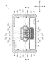
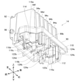
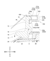
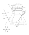
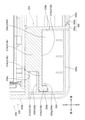
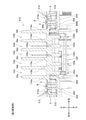
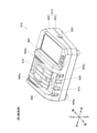
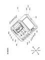
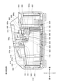
- FIG. 1 It is a block diagram of the equipment system 2 which concerns on 1st Embodiment. It is a perspective view which looked at the charger 10 which concerns on 1st Embodiment from the left upper front. It is a top view which looked at the charger 10 which concerns on 1st Embodiment from above. It is sectional drawing along the IV-IV line of FIG. It is sectional drawing along the VV line of FIG. It is sectional drawing which follows the VI-VI line of FIG. In the first embodiment, it is a perspective view which looked at the charger 10 in the state which the terminal unit 14 was removed from the left upper front. It is an exploded view of the terminal unit 14 and the hook 16 which concerns on 1st Embodiment.
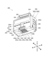
- FIG. 3 is a perspective sectional view of the vicinity of the right engaging portion 210a of the battery pack 200 according to the first embodiment as viewed from the lower left front. It is a front sectional view of the battery pack 200 which concerns on 1st Embodiment. In the first embodiment, it is a perspective view which looked at the battery pack 200 with the terminal cover 250 attached from the lower left front.
- FIG. 6 is a cross-sectional view taken along the line XXVII-XXVII of FIG.
- FIG. 3 is a perspective view of the charger 610 according to the third embodiment as viewed from the upper left front.
- it is a perspective view of the charger 610 in the state where the terminal cover 616 is removed, as viewed from the upper left front.
- it is a perspective view of the charger 610 in a state where the terminal cover 616, the terminal unit 618, and the springs 672 and 674 are removed, as viewed from the upper left front.
- it is a top view of the charger 610 in a state where the terminal cover 616, the terminal unit 618, and the springs 672 and 674 are removed, as viewed from above.
- FIG. 3 is a perspective view of the charger 610 according to the third embodiment as viewed from the upper left front.
- it is a perspective view of the charger 610 in the state where the terminal cover 616 is removed, as viewed from the upper left front.
- it is a perspective view of the charger 610 in a state where the terminal cover 616, the terminal unit 618, and
- FIG. 3 is a perspective view of the terminal unit 618 according to the third embodiment as viewed from the upper left front.
- FIG. 3 is a perspective view of the terminal unit 618 according to the third embodiment as viewed from the lower left front. It is sectional drawing which saw the charger 610 which concerns on 3rd Embodiment from the left. It is sectional drawing which saw the charger 610 which concerns on 3rd Embodiment from the left. It is sectional drawing which saw the charger 610 which concerns on 3rd Embodiment from the left.
- the electrical device covers the upper wall provided with the opening, the main body case provided with the bottom wall, and the opening from above, and the device side corresponding to the battery side terminal.
- a terminal unit having a terminal is provided, and at least a part around the opening is provided with a first rib extending upward from the upper surface of the upper wall, and when the electric device is viewed from above, the electric device is provided.
- the first rib may overlap the terminal unit.
- the first rib may be in contact with the lower surface of the terminal unit.
- the lower surface of the terminal unit may be provided with a second rib extending downward from the lower surface.
- the first rib and the second rib may face each other.
- the second rib can prevent water from entering the opening side beyond the first rib. Therefore, it is possible to further prevent water from entering the inside of the main body case of the electric device.
- the upper surface may be provided with an inclined portion that is inclined so that the first side in the first direction orthogonal to the vertical direction is located below the second side.
- the first rib may be provided on the second side of the opening in the first direction.
- the water that reaches the upper surface of the upper wall on the second side of the opening flows from the second side to the first side. Then, the water that has reached the first rib flows in the vertical direction and the direction orthogonal to the first direction, and then further flows from the second side to the first side. That is, water flows outside the opening. Therefore, it is possible to prevent water from accumulating around the opening, and it is possible to prevent water from entering the inside of the main body case of the electric device through the opening.
- the body case is provided with a through hole that penetrates the upper wall in the vertical direction, and the terminal unit extends downward from the lower surface and has a shape corresponding to the through hole, and is below. It may be provided with a protrusion to which a screw can be attached from the side.
- the diameter of the through hole may be larger than the outer diameter of the protruding portion, and the outer diameter of the flange portion of the screw may be larger than the diameter of the through hole.
- the device side terminal and the battery side terminal will be deformed due to unintended contact between the device side terminal and the battery side terminal.
- the terminal unit can move in the horizontal direction with respect to the main body case in the state where the terminal unit and the main body case are assembled.
- the position of the device-side terminal with respect to the battery-side terminal in the horizontal direction is displaced, the position of the device-side terminal with respect to the battery-side terminal becomes the correct position by moving the terminal unit with respect to the battery pack. Therefore, when the battery pack is attached to an electric device, it is possible to suppress the occurrence of unintended contact between the device side terminal and the battery side terminal, and it is possible to suppress the deformation of the device side terminal and the battery side terminal. Can be done.
- the body case comprises two facing through holes across an opening and the terminal unit comprises two protrusions corresponding to the two through holes. You may.
- the main body case can be firmly held by the screws and the terminal unit.
- the electrical device may further be attached to the terminal unit on the outside of the body case and provided with an engageable hook in the groove of the battery pack.
- the hook When the hook is attached to the terminal unit inside the main body case, it is necessary to provide an opening in the main body case for the hook to extend from the inside to the outside of the main body case. In this case, water may enter the inside of the main body case of the electric device through the opening. According to the above configuration, since the hook is attached to the terminal unit on the outside of the main body case, it is not necessary to provide the main body case with an opening for the hook to extend from the inside to the outside of the main body case. Therefore, it is possible to prevent water from entering the inside of the main body case of the electric device.
- the electrical equipment may further include a terminal cover attached to the upper wall of the body case.
- the terminal cover may cover a part of the terminal unit and a part of the upper wall from above.
- the terminal unit since the terminal unit covers a part of the upper wall, water from above is further suppressed from entering the inside of the main body case.
- the electrical device may be a charger.
- the terminal unit and the first rib can prevent water from entering the inside of the main body case of the charger.
- the equipment system 2 includes a battery pack 200 and a charger 10 to which the battery pack 200 can be attached and detached.
- the charger 10 is a battery-related device for charging the battery pack 200.
- the battery pack 200 is a power source for supplying electric power to a working machine (not shown) such as a lawn mower.
- the battery pack 200 is configured to be removable from the working machine.
- the charger 10 is configured to charge the battery pack 200 in a state of being removed from the working machine. In the following, when the charger 10 of FIG.
- the direction orthogonal to the mounting surface is referred to as the vertical direction
- the direction orthogonal to the vertical direction is referred to as the horizontal direction
- the vertical direction and the horizontal direction are used.
- the direction orthogonal to is called the front-back direction.
- the charger 10 includes a main body case 12, a terminal unit 14, and a hook 16.
- the main body case 12 includes an upper case 20 and a lower case 22.
- the upper case 20 and the lower case 22 are fixed by screws (not shown).
- the bottom wall 22a of the lower case 22 faces the mounting surface.
- a cord outlet 24 defined by fixing the upper case 20 and the lower case 22 is provided.
- the cord outlet 24 is a hole for passing a power cord (not shown).
- the upper wall 20a of the upper case 20 is composed of a front upper wall 30, a rear upper wall 32, and a central upper wall 34.
- the front upper wall 30 is provided in front of the rear upper wall 32, and is inclined so that the front side is inclined downward.
- the front upper wall 30 is provided with a display unit 36 indicating the state of charge of the battery pack 200.
- the central upper wall 34 is surrounded by the front upper wall 30 and the rear upper wall 32.
- the height of the central upper wall 34 is lower than the height of the rear upper wall 32.
- the central upper wall 34 is inclined so that the front side is inclined downward.
- the tilt angle of the central upper wall 34 is smaller than the tilt angle of the front upper wall 30.
- the central upper wall 34 is provided with an opening 40.
- An upper rib 50 extending upward from the upper surface 34a of the central upper wall 34 is provided around the opening 40.
- the upper rib 50 surrounds the entire circumference of the opening 40.
- Mounting portions 52 and 54 are provided on both the left and right sides of the upper rib 50. As shown in FIG. 4, the mounting portions 52 and 54 have through holes 52a and 54a that penetrate the central upper wall 34 and the upper rib 50 in the vertical direction.
- the mounting portions 52 and 54 are used to mount the terminal unit 14 on the upper case 20. As shown in FIG. 2, the terminal unit 14 covers the opening 40 from above.
- the upper case 20 further includes an upright portion 42.
- the upright portion 42 includes a front upright portion 44 extending upward from the front upper wall 30 and a rear upright portion 46 extending upward from the rear upper wall 32.
- the front standing portion 44 is formed at the right end portion and the left end portion of the front upper wall 30.
- the upper end of the front standing portion 44 is inclined so that the front side is inclined downward.
- the rear standing portion 46 is formed at the right end portion, the left end portion, and the rear end portion of the rear upper wall 32.
- a front rail 46a and a rear rail 46b projecting to the left are provided on the right wall of the rear standing portion 46. As shown in FIG.
- a front rail 46a and a rear rail 46b projecting to the right are provided on the left wall of the rear standing portion 46.
- the front rail 46a and the rear rail 46b extend in the vertical direction.
- the front rail 46a and the rear rail 46b provided on the right wall have shapes corresponding to the first right guide groove 260 and the second right guide groove 262 (see FIG. 17) of the battery pack 200, which will be described later, respectively.
- the front rail 46a and the rear rail 46b provided on the left wall have shapes corresponding to the first left guide groove 264 and the second left guide groove 266 (see FIG. 16) of the battery pack 200, which will be described later, respectively.
- the front rail 46a and the rear rail 46b define the sliding direction (vertical direction in this embodiment) of the battery pack 200.
- a recess 48 is provided between the rear wall on the left side and the rear wall on the right side of the rear standing portion 46.
- the hook 16 includes an operating portion 70, a rear wall portion 72 extending upward from the rear end of the operating portion 70, an engaging portion 74, a connecting portion 76, and a rear protruding portion 78. Be prepared.
- the operation unit 70 is operated by an operator when removing the battery pack 200 from the charger 10.
- the engaging portion 74 and the connecting portion 76 extend rearward from the left and right ends of the rear wall portion 72.
- the upper surface of the engaging portion 74 is inclined so that the rear side is inclined downward, and the lower surface of the engaging portion 74 is substantially parallel to the plane including the front-rear direction and the left-right direction.
- the engaging portion 74 is provided at the upper end of the rear wall portion 72.
- the connecting portion 76 is provided below the engaging portion 74.
- the connecting portion 76 is provided with a recess 80 having a shape corresponding to the lateral protrusions 96 and 98 of the terminal unit 14, which will be described later.
- the rear protrusion 78 extends rearward from the rear wall portion 72.
- the rear protrusion 78 is provided below the connecting portion 76.
- a spring 140 is attached to the rear protrusion 78.
- the upper end of the hook 16 is located below the upper end of the front standing portion 44.
- the distance D1 between the upper end of the hook 16 and the upper end of the front standing portion 44 is 2 [mm] when the hook 16 is not operated by the operator.
- the terminal unit 14 includes a base 90, a front rib 92 extending upward from the upper surface 90a of the base 90, and side ribs 94a to 94f extending upward from the upper surface 90a.
- the lateral ribs 94a to 94f extend along a plane including the front-back direction and the up-down direction.
- the side ribs 94a to 94f are provided at intervals in the left-right direction.
- the front rib 92 extends along a plane including the left-right direction and the up-down direction, and connects the front portions of the side ribs 94a to 94f.
- a lateral protrusion 96 projecting to the left is provided at the lower front portion of the lateral rib 94f arranged on the leftmost side.
- a lateral protrusion 98 projecting to the right is provided at the lower front portion of the lateral rib 94a arranged on the far right side.
- the lateral protrusions 96 and 98 When viewed from the left-right direction, the lateral protrusions 96 and 98 have a circular shape.
- the lateral protrusions 96 and 98 project along the axis A extending in the left-right direction.
- the hook 16 can be attached to the terminal unit 14 by inserting the lateral protrusions 96 and 98 into the recess 80 of the hook 16.
- the hook 16 In a state where the hook 16 is attached to the terminal unit 14, the hook 16 can rotate with respect to the terminal unit 14 about the axis A of the lateral protrusions 96 and 98 as a rotation axis. As shown in FIG. 9, a recess 100 is provided in the lower portion of the front rib 92. A part of the spring 140 is arranged in the recessed portion 100 in a state where the hook 16 is attached to the terminal unit 14.
- a plurality of device-side terminals 120 are attached to the base 90 of the terminal unit 14.
- the plurality of device-side terminals 120 include charging terminals 122a and 122b used for charging the battery pack 200, and signal terminals 124a to 124e used for transmitting and receiving signals to and from the battery pack 200. ..
- the upper surface 90a of the base 90 is divided into five terminal regions TR1 to TR5 by the front ribs 92 and the side ribs 94a to 94f.
- the terminal areas TR1 and TR5 are provided with charging terminals 122a and 122b, respectively.
- the terminal area TR2 is provided with a signal terminal 124a.
- the terminal area TR3 is provided with signal terminals 124b and 124c.
- the terminal area TR4 is provided with signal terminals 124d and 124e.
- the charging terminals 122a and 122b are provided outside the signal terminals 124a to 124e in the left-right direction.
- the charging terminal 122a is provided on the right side of the signal terminals 124a to 124e, and the charging terminal 122b is provided on the left side of the signal terminals 124a to 124e.
- the signal terminals 124b and 124c are provided side by side in the front-rear direction.
- the signal terminals 124d and 124e are provided side by side in the front-rear direction.
- the signal terminal 124a is provided between the charging terminal 122a and the signal terminal 124b in the left-right direction.
- the lower portions of the charging terminals 122a and 122b and the signal terminals 124a to 124e are connected to the terminal board 130 (see FIGS. 4 to 6) housed in the main body case 12.
- a step portion 102 for changing the height of the partial RP3 is provided.
- the front side portion FP3 is tilted so that the front side is tilted downward
- the rear side portion RP3 is tilted so that the rear side is tilted downward.
- the front side portion FP3 is inclined so that the signal terminal 124b side is located below the step portion 102 side
- the rear side portion RP3 is positioned so that the signal terminal 124c side is located below the step portion 102 side. Is inclined to.
- a drain hole 104 for draining water that has reached the front portion FP3 of the terminal region TR3 is provided in the lower portion of the front rib 92 that defines the terminal region TR3.
- the structure in the terminal area TR4 is the same as the structure in the terminal area TR3 except that the signal terminals 124d and 124e are provided.
- a boundary portion 106 is provided between the charging terminal 122a and the front rib 92.
- the front portion FP1 on the front side of the boundary portion 106 is inclined so that the front side is inclined downward
- the posterior portion RP1 on the rear side of the boundary portion 106 is inclined so that the rear side is inclined downward. It is tilted.
- a drain hole 104 is provided in the lower portion of the front rib 92 that defines the terminal region TR1.
- the shapes in the terminal regions TR2 and TR5 have the same shape as in the terminal regions TR1 except that the charging terminal 122b and the signal terminal 124a are provided.
- the terminal unit 14 further includes a lower rib 110, two boss portions 112 and 114, and terminal fixing portions 116a to 116e.
- the lower rib 110 extends downward from the lower surface 90b of the base 90.
- the inner contour of the lower rib 110 has a shape corresponding to the outer contour of the upper rib 50 (see FIG. 7) of the upper case 20.
- the lower rib 110 is provided so as to be located outside the upper rib 50 of the upper case 20.
- the drainage hole 104 is provided on the front rib 92 side of the lower rib 110.
- the terminal fixing portions 116a to 116e extend downward from the lower surface 90b of the base 90.
- the charging terminal 122a is fixed to the terminal fixing portion 116a
- the signal terminal 124a is fixed to the terminal fixing portion 116b
- the signal terminals 124b and 124c are fixed to the terminal fixing portion 116c.
- the signal terminals 124d and 124e are fixed to the 116d
- the charging terminal 122b is fixed to the terminal fixing portion 116e.
- the boss portions 112 and 114 extend downward from the lower surface 90b.
- the boss portions 112 and 114 are provided at positions corresponding to the mounting portions 52 and 54 of the upper case 20, respectively. As shown in FIG. 4, the outer diameters of the boss portions 112 and 114 are smaller than the diameters of the through holes 52a and 54a of the mounting portions 52 and 54.
- a screw B having a flange portion C having an outer diameter larger than the diameter of the through holes 52a and 54a is screwed into the boss portions 112 and 114.
- the terminal unit 14 is attached to the main body case 12 by sandwiching the attachment portions 52 and 54 of the main body case 12 between the flange portion C of the screw B and the lower surface 90b of the base portion 90 of the terminal unit 14.
- the base 90 of the terminal unit 14 can be said to be a part of the upper wall 20a of the main body case 12.
- a gap S is provided in the left-right direction between the boss portions 112 and 114 and the attachment portions 52 and 54.
- a gap S is also provided in the left-right direction between the lower rib 110 of the terminal unit 14 and the upper rib 50 of the upper case 20. That is, the terminal unit 14 can move slightly in the horizontal direction with respect to the main body case 12.
- the screw B does not have to have a flange portion.
- a washer having an outer diameter larger than that of the through holes 52a and 54a may be used.
- the battery pack 200 includes a housing 202.
- the housing 202 is composed of a front housing 202a and a rear housing 202b.
- the housing 202 includes a main body portion 220, a right side support portion 222, a left side support portion 224, and a grip portion 226.
- the main body 220 has a substantially rectangular parallelepiped shape.
- the right side support portion 222 projects upward from the vicinity of the right end of the upper surface of the main body portion 220.
- the left support portion 224 projects upward from the vicinity of the left end of the upper surface of the main body portion 220.
- the grip portion 226 extends in the left-right direction, and connects the vicinity of the upper end of the left surface of the right side support portion 222 and the vicinity of the upper end of the right surface of the left side support portion 224.
- the weight of the battery pack 200 is, for example, in the range of 1.0 kg to 4.0 kg, more specifically 2.2 kg.
- the rated voltage of the battery pack 200 is, for example, in the range of 36V-108V, more specifically 57.6V.
- the rated capacity of the battery pack 200 is, for example, in the range of 3.0Ah-12.0Ah, more specifically 4.0Ah.
- a terminal interface (hereinafter, may be referred to as "IF") portion 230 is formed in the front lower portion near the center in the left-right direction of the main body portion 220.
- the terminal IF portion 230 has a concave shape in which the front portion and the lower portion are open.
- the terminal IF portion 230 includes an IF upper surface 230a, an IF rear surface 230b, an IF right surface 230c, and an IF left surface 230d (see FIG. 17).
- the IF upper surface 230a is oriented in the front-rear direction and the left-right direction, faces downward, and is arranged offset upward from the lower surface 220a of the main body 220.
- the IF rear surface 230b is aligned in the vertical direction and the horizontal direction, faces forward, and is arranged so as to be offset rearward from the front surface 220b of the main body portion 220.
- the IF right surface 230c is arranged along the front-rear direction and the up-down direction, and faces left.
- the IF left surface 230d (see FIG. 17) is arranged along the front-rear direction and the up-down direction, and faces the right side.
- the terminal IF unit 230 includes a plurality of terminal accommodating units 232 to 240 arranged side by side in the left-right direction between the IF right surface 230c and the IF left surface 230d.
- the terminal accommodating portions 232 to 240 extend forward from the IF rear surface 230b of the terminal IF portion 230, and extend downward from the IF upper surface 230a of the terminal IF portion 230.
- the lower surfaces of the terminal accommodating portions 232 to 240 are arranged above the lower surface 220a of the main body portion 220 and substantially on the same plane.
- the front surfaces of the terminal accommodating portions 232 to 240 are arranged on substantially the same plane behind the front surface 220b of the main body portion 220.
- Terminal openings 232a to 240a are formed on the lower surfaces of the terminal accommodating portions 232 to 240.
- the terminal openings 232a to 240a are slit-shaped through holes having a longitudinal direction in the front-rear direction.
- a plurality of battery-side terminals 242 are accommodated in the terminal accommodating portions 232 to 240.
- the plurality of battery-side terminals 242 include battery-side power terminals 244a and 244b, and battery-side signal terminals 246a to 246f.
- the battery-side power terminal 244a is housed in the rightmost terminal accommodating portion 232.
- the battery-side power terminal 244b is housed in the leftmost terminal accommodating portion 240.
- the battery-side signal terminals 246a and 246b are housed in the terminal accommodating portion 234 on the left side of the terminal accommodating portion 232 on the far right.
- the battery-side signal terminals 246a and 246b are provided side by side in the front-rear direction.
- the battery-side signal terminals 246c and 246d are housed in the central terminal accommodating portion 236.
- the battery-side signal terminals 246c and 246d are provided side by side in the front-rear direction.
- the battery-side signal terminals 246e and 246f are housed in the terminal accommodating portion 238 on the right side of the terminal accommodating portion 240 on the leftmost side.
- the battery-side signal terminals 246e and 246f are provided side by side in the front-rear direction.
- the battery-side power terminals 244a and 244b are terminals corresponding to the charging terminals 122a and 122b (see FIG. 3) of the charger 10, respectively.
- the battery-side power terminals 244a and 244b are used for charging when the battery pack 200 is attached to the charger 10.
- the battery-side signal terminals 246a and 246c to 246f are terminals corresponding to the signal terminals 124a and 124b to 124e (see FIG. 3) of the charger 10, respectively.
- the battery-side signal terminals 246a, 246c to 246f are used for transmitting and receiving signals to and from the charger 10 when the battery pack 200 is attached to the charger 10.
- the battery-side power terminals 244a and 244b are connected to the device-side power terminals of the working machine and are used for discharging.
- the battery side signal terminals 246b to 246f are connected to the device side signal terminals of the working machine, respectively, to transmit and receive signals to and from the working machine. used.
- a right engaging portion 210a projecting to the left is formed on the IF right surface 230c of the terminal IF portion 230.
- a left engaging portion 210b projecting to the right is formed on the IF left surface 230d of the terminal IF portion 230.
- the right engaging portion 210a and the left engaging portion 210b have positions and shapes symmetrical with each other.
- the right engaging portion 210a has an upper end connected to the IF upper surface 230a and a rear end connected to the IF rear surface 230b, and the right base portion 214a and the right base portion 214a from the lower part of the front end to the front.
- the left engaging portion 210b has a left base portion 214b whose upper end is connected to the IF upper surface 230a and whose rear end is connected to the IF rear surface 230b and a left extending forward from the lower front end of the left base portion 214b.
- the IF upper surface 230a, the left base portion 214b, and the left extending portion 216b define the left groove portion 212b extending in the front-rear direction.
- the right groove portion 212a and the left groove portion 212b are provided in the vicinity of the plurality of battery-side terminals 242.
- the engaging portion 74 (see FIG. 8) of the hook 16 of the charger 10 is engaged with the right groove portion 212a and the left groove portion 212b.
- the terminal cover 250 can be attached to and detached from the terminal IF portion 230.
- the terminal cover 250 can be attached to the terminal IF portion 230 by sliding it backward with respect to the terminal IF portion 230. Further, the terminal cover 250 can be removed from the terminal IF portion 230 by sliding it forward with respect to the terminal IF portion 230.
- the terminal cover 250 includes a lower plate portion 250a, a front plate portion 250b, a right plate portion 250c, and a left plate portion 250d (see FIG. 23).
- the terminal cover 250 is, for example, a resin member, and the lower plate portion 250a, the front plate portion 250b, the right plate portion 250c, and the left plate portion 250d are integrally formed.
- the lower plate portion 250a has a substantially flat plate shape along the front-rear direction and the left-right direction.
- the lower plate portion 250a has a substantially rectangular shape with the longitudinal direction along the left-right direction and the lateral direction along the front-rear direction.
- a finger hook convex portion 250e that projects downward and extends in the left-right direction is formed on the lower surface of the lower plate portion 250a.
- the finger rest convex portion 250e is arranged behind the center of the lower plate portion 250a in the front-rear direction.
- the front plate portion 250b extends upward from the front end of the lower plate portion 250a.
- the front plate portion 250b has a flat plate shape along the vertical direction and the horizontal direction.
- the front plate portion 250b has a substantially rectangular shape in which the longitudinal direction is along the left-right direction and the lateral direction is along the up-down direction.
- a right rail 250f projecting to the right and a right engaging convex portion 250g projecting to the right are further formed.
- the right rail 250f extends along the front-rear direction.
- the right plate portion 250c is formed with an upper slit 250h extending in the front-rear direction above the right engaging convex portion 250g and a lower slit 250i extending in the front-rear direction below the right engaging convex portion 250g.
- a left rail 250j projecting to the left and a left engaging convex portion 250k projecting to the left are further formed on the left surface of the left plate portion 250d. ing.
- the left rail 250j extends in the front-rear direction.
- the left plate portion 250d is formed with an upper slit 250l extending in the front-rear direction above the left engaging convex portion 250k and a lower slit 250m extending in the front-rear direction below the left engaging convex portion 250k.
- the left engaging convex portion 250k When the 250k comes into contact with the left tip portion 218b of the left engaging portion 210b, the left engaging convex portion 250k is elastically deformed to the right. Then, when the right engaging convex portion 250 g moves rearward from the right tip portion 218a of the right engaging portion 210a, the elastic deformation of the right engaging convex portion 250 g is released, so that the right engaging convex portion 250 g is moved to the right. When the left engaging convex portion 250k moves rearward from the left tip portion 218b of the left engaging portion 210b while engaging with the right tip portion 218a of the engaging portion 210a, the elastic deformation of the left engaging convex portion 250k is released.
- the left engaging convex portion 250k engages with the left tip portion 218b of the left engaging portion 210b.
- the terminal cover 250 is fixed to the terminal IF portion 230.
- the right engaging portion 210a, the right groove portion 212a, the right base portion 214a, the right extending portion 216a, the left engaging portion 210b, the left groove portion 212b, the left base portion 214b, and the left extending portion 216b are collectively referred to as "cover mounting”.
- Part 252 may be described.
- the terminal cover 250 when the terminal cover 250 is attached to the terminal IF portion 230 (specifically, the cover mounting portion 252), the terminal accommodating portions 232 to 240 (see FIG. 16) are provided by the lower plate portion 250a of the terminal cover 250. ) And the terminal openings 232a to 240a (see FIG. 16) of the terminal accommodating portions 232 to 240 are covered. Further, in a state where the terminal cover 250 is attached to the terminal IF portion 230, the front surface of the terminal accommodating portions 232 to 240 (see FIG. 16) is covered by the front plate portion 250b of the terminal cover 250.
- the user When removing the terminal cover 250 from the terminal IF portion 230, the user puts his finger on the finger rest convex portion 250e and slides the terminal cover 250 forward with respect to the terminal IF portion 230.
- the right engaging convex portion 250g of the terminal cover 250 (see FIG. 24) is disengaged from the right tip portion 218a of the right engaging portion 210a, and the left engaging convex portion 250k of the terminal cover 250 (FIG. 24). (See) is disengaged from the left tip portion 218b of the left engaging portion 210b, so that the terminal cover 250 is removed from the terminal IF portion 230.
- the right surface 220c of the main body 220 is formed with a first right guide groove 260 extending in the vertical direction and a second right guide groove 262 extending in the vertical direction.
- the first right guide groove 260 is arranged between the center of the right surface 220c in the front-rear direction and the front end of the right surface 220c near the front end of the right surface 220c
- the second right guide groove 262 is the center of the right surface 220c in the front-rear direction. It is arranged between the rear end of the right surface 220c and the rear end of the right surface 220c.
- the first right guide groove 260 and the second right guide groove 262 are provided at positions corresponding to the front rail 46a and the rear rail 46b (see FIG.
- the left surface 220d of the main body 220 is formed with a first left guide groove 264 extending in the vertical direction and a second left guide groove 266 extending in the vertical direction.
- the first left guide groove 264 is arranged between the center of the left surface 220d in the front-rear direction and the front end of the left surface 220d toward the front end of the left surface 220d
- the second left guide groove 266 is the center of the left surface 220d in the front-rear direction. It is arranged between the rear end of the left surface 220d and the rear end of the left surface 220d.
- the first left guide groove 264 and the second left guide groove 266 are provided at positions corresponding to the front rail 46a and the rear rail 46b (see FIG. 3) on the left side of the charger 10, respectively.
- the first right guide groove 260 and the first left guide groove 264 have positions and shapes symmetrical with each other.
- the second right guide groove 262 and the second left guide groove 266 have positions and shapes symmetrical with each other.
- FIG. 12 in the state where the battery pack 200 is not attached, the hook 16 is urged by the spring 140 (see FIG. 8) so that the rear wall portion 72 is substantially parallel to the vertical direction. ing.
- the lower end and the left engaging portion of the right tip portion 218a of the right engaging portion 210a of the battery pack 200 are used.
- the lower end of the left tip portion 218b of the 210b comes into contact with the engaging portion 74 of the hook 16 of the charger 10.
- FIG. 13 when the operator further lowers the battery pack 200, the hook 16 rotates with the shaft A as the rotation shaft. Specifically, the engaging portion 74 moves forward and the operating portion 70 moves downward.
- the upper end of the right extension portion 216a of the right engagement portion 210a of the battery pack 200 and the upper end of the left extension portion 216b of the left engagement portion 210b are the engagement portions 74 of the hook 16 of the charger 10.
- the hook 16 is moved downward, the hook 16 is rotated around the shaft A by the urging force of the spring 140. Specifically, the engaging portion 74 moves backward and the operating portion 70 moves upward. As a result, the engaging portion 74 of the charger 10 enters the right groove portion 212a and the left groove portion 212b of the battery pack 200.
- the state shown in FIG. 14 is a state in which the hook 16 is engaged with the right groove portion 212a and the left groove portion 212b of the battery pack 200, and the battery pack 200 is fixed to the charger 10.
- the position of the hook 16 for fixing the battery pack 200 to the charger 10 may be referred to as a lock position. In this state, the battery pack 200 is charged.
- the operator removes the battery pack 200 from the charger 10.
- the operator pushes down the operation unit 70 of the hook 16.
- the hook 16 rotates with the shaft A as the rotation shaft, and the engaging portion 74 moves forward.
- the engaging portion 74 is not arranged above the right extending portion 216a of the right engaging portion 210a of the battery pack 200 and the left extending portion 216b of the left engaging portion 210b. Therefore, the operator can move the battery pack 200 upward and can remove the battery pack 200 from the charger 10.
- the position of the hook 16 that does not fix the battery pack 200 to the charger 10 may be referred to as an unlock position.
- the operator releases his / her hand from the operation unit 70 of the hook 16.
- the hook 16 is rotated around the shaft A by the urging force of the spring 140. Specifically, the engaging portion 74 moves rearward and the operating portion 70 moves upward, so that the position of the hook 16 is changed from the unlocked position to the locked position.
- the charger 10 covers the central upper wall 34 provided with the opening 40, the main body case 12 provided with the bottom wall 22a, and the opening 40.
- a terminal unit 14 having a device-side terminal 120 corresponding to the battery-side terminal 242 is provided, and at least a part around the opening 40 is provided with an upper rib 50 extending upward from the upper surface 34a of the central upper wall 34. There is.
- the upper rib 50 overlaps the terminal unit 14. According to the above configuration, since the terminal unit 14 covers the opening 40 of the central upper wall 34 from above, water from above is suppressed from entering the inside of the main body case 12. Further, the upper rib 50 can prevent water that has reached the upper surface 34a outside the opening 40 and the upper rib 50 from passing through the opening 40 and entering the main body case 12. Therefore, it is possible to prevent water from entering the inside of the main body case 12 of the charger 10.
- the upper rib 50 contacts the lower surface of the lower surface 90b of the base 90 of the terminal unit 14. According to the above configuration, it is possible to prevent the water that has reached the upper end of the upper rib 50 from entering the inside of the main body case 12.
- the charger 10 extends downward from the lower surface 90b to the lower surface 90b of the base 90 of the terminal unit 14, and extends downward from the lower surface 90b to the upper surface 34a of the central upper wall 34 of the charger 10.
- a lower rib 110 that comes into contact with the charger is provided.
- the upper rib 50 and the lower rib 110 face each other. According to the above configuration, the lower rib 110 can prevent water from entering the opening 40 side beyond the upper rib 50. Therefore, it is possible to further prevent water from entering the inside of the main body case 12 of the charger 10.
- the charger 10 according to the embodiment is inclined so that the front side in the front-rear direction is located below the rear side on the upper surface 34a of the central upper wall 34 of the charger 10.
- An inclined portion is provided.
- the upper rib 50 may be provided behind the opening 40 in the front-rear direction.
- the water that has reached the upper surface 34a of the central upper wall 34 behind the opening 40 flows from the rear side to the front side.
- the water that has reached the upper rib 50 flows in the left-right direction, and then further flows from the rear side to the front side. That is, water flows outside the opening 40. Therefore, it is possible to prevent water from accumulating around the opening 40, and it is possible to prevent water from entering the inside of the main body case 12 of the charger 10 through the opening 40.
- the charger 10 has a main body case 12 provided with through holes 52a and 54a that vertically penetrate the central upper wall 34, and is a terminal unit.
- the 14 has a shape extending downward from the lower surface 90b of the base 90 and corresponding to the through holes 52a and 54a, and includes boss portions 112 and 114 to which the screw B can be attached from the lower side.
- the diameters of the through holes 52a and 54a are larger than the outer diameters of the boss portions 112 and 114, and the outer diameter of the flange portion C of the screw B is larger than the diameters of the through holes 52a and 54a.
- the terminal unit 14 can move in the horizontal direction with respect to the main body case 12. Therefore, even if the position of the device-side terminal 120 with respect to the battery-side terminal 242 in the horizontal direction is displaced, the position of the device-side terminal 120 with respect to the battery-side terminal 242 is caused by the movement of the terminal unit 14 with respect to the battery pack 200. It will be in the correct position. Therefore, when the battery pack 200 is attached to the charger 10, it is possible to suppress the occurrence of unintended contact between the device side terminal 120 and the battery side terminal 242, and the device side terminal 120 and the battery side terminal 242 are deformed. Can be suppressed.
- the main body case 12 includes two through holes 52a and 54a facing each other with the opening 40 interposed therebetween, and the terminal unit 14 has a terminal unit 14. It is provided with two boss portions 112 and 114 corresponding to the two through holes 52a and 54a. According to the above configuration, the main body case 12 can be firmly sandwiched by the screw B and the terminal unit 14.
- the charger 10 further has the charger 10 attached to the terminal unit 14 on the outside of the main body case 12, and has a right groove portion 212a and a left groove portion of the battery pack 200.
- a hook 16 that can be engaged with the 212b is provided.
- the main body case 12 since the hook 16 is attached to the terminal unit 14 on the outside of the main body case 12, the main body case 12 is not provided with an opening for the hook 16 to extend from the inside to the outside of the main body case 12. You may. Therefore, it is possible to prevent water from entering the inside of the main body case 12 of the charger 10.
- the charger 10 is an example of an "electrical device".
- the central upper wall 34 is an example of the "upper wall”.
- the upper rib 50 is an example of the "first rib”.
- the lower rib 110 is an example of the "second rib”.
- the front-rear direction, the front side, and the rear side are examples of the "first direction", the "first side", and the “second side", respectively.
- the boss portions 112 and 114 are examples of "protruding portions”.
- the charger 410 of this embodiment will be described with reference to FIGS. 26 and 27.
- the charger 410 of the present embodiment has a terminal unit 414 and a structure of the central upper wall 434 of the main body case 12 different from that of the charger 10 of the first embodiment.
- the same reference numerals will be given to the structures common to the embodiments, and the description thereof will be omitted.
- the terminal unit 414 includes a lower rib 510 extending downward from the lower surface 490b of the base 490. Between the side rib 94a arranged on the rightmost side of the terminal unit 414 and the lower rib 510, and between the side rib 94f arranged on the leftmost side of the terminal unit 414 and the upper rib 50, Mounting portions 512 and 514 are provided. The mounting portions 512 and 514 have through holes 512a and 514a that vertically penetrate the base portion 490 of the terminal unit 414.
- an upper rib 450 extending upward from the upper surface of the central upper wall 434 is provided.
- a side rib 94a arranged on the rightmost side of the terminal unit 414 and a boss portion 452 on the right side of the upper rib 450 are provided, and a side rib 94f arranged on the leftmost side of the terminal unit 414.
- the boss portion 454 is provided on the left side of the upper rib 450.
- the boss portions 452 and 454 extend upward from the upper surface of the central upper wall 434.
- the boss portions 452 and 454 are provided at positions corresponding to the mounting portions 512 and 514 of the terminal unit 414, respectively.
- the outer diameter of the boss portions 452 and 454 is smaller than the diameter of the through holes 512a and 514a of the mounting portions 512 and 514.
- a screw B having a flange portion C having an outer diameter larger than the diameter of the through holes 512a and 514a is screwed into the boss portions 452 and 454.
- the terminal unit 414 is attached to the main body case 12 by sandwiching the terminal unit 414 between the screw B and the main body case 12. In a state where the terminal unit 414 is attached to the main body case 12, a gap S is provided in the left-right direction between the boss portions 452 and 454 and the attachment portions 512 and 514. Therefore, the terminal unit 414 can move slightly in the horizontal direction with respect to the main body case 12. Even with such a configuration, the same effect as that of the charger 10 of the first embodiment can be obtained.
- the charger 610 of this embodiment will be described with reference to FIGS. 28 to 35.
- the battery pack (not shown) that can be attached to the charger 610 of this embodiment is different from the battery pack 200 that can be attached to the charger 10 of the first embodiment.
- the charger 610 includes a main body case 612, a battery pack mounting portion 614, a terminal cover 616, and a terminal unit 618 (see FIG. 29).
- the main body case 612 includes an upper case 620 and a lower case 622.
- the upper case 620 and the lower case 622 are fixed by screws (not shown).
- the bottom wall 622a of the lower case 622 faces the mounting surface.
- a cord outlet 624 defined by the upper case 620 and the lower case 622 is provided on the left side surface of the main body case 612.
- the cord outlet 624 is a hole for passing a power cord (not shown).
- the battery pack mounting portion 614 is provided on the right side of the charger 610.
- the terminal cover 616 and the terminal unit 618 are provided in the battery pack mounting portion 614.
- the upper wall 620a of the upper case 620 where the battery pack mounting portion 614 is provided is composed of an outer upper wall 630 and an inner upper wall 632. ..
- the inner upper wall 632 is surrounded by the outer upper wall 630.
- the outer upper wall 630 is inclined so that the front side is inclined downward.
- the height of the inner upper wall 632 is lower than the height of the outer upper wall 630.
- the inner upper wall 632 is inclined so that the rear side is inclined downward.
- the portion provided with the cylindrical rib 640 described later (hereinafter, may be referred to as “unit mounting portion 634”) is parallel to the plane including the left-right direction and the front-back direction. be.
- the unit mounting portion 634 has a through hole 634a that penetrates the inner upper wall 632 in the vertical direction.
- the outer upper wall 630 and the inner upper wall 632 are connected by a connecting wall 633 extending in the vertical direction.
- the inner upper wall 632 is provided with an opening 636.
- an upper rib 638 extending upward from the upper surface 632a of the inner upper wall 632 is provided.
- the upper rib 638 surrounds the entire circumference of the opening 636.
- the upper rib 638 comprises a cylindrical rib 640.
- the cylindrical rib 640 is provided at the rear end of the opening 636 near the center of the opening 636 in the left-right direction.
- the cylindrical rib 640 extends upward from the unit mounting portion 634 (ie, the inner upper wall 632).
- the inner diameter of the cylindrical rib 640 is larger than the diameter of the through hole 634a of the unit mounting portion 634.
- the upper end of the cylindrical rib 640 is inclined so that the front side is inclined downward.
- the upper case 620 is provided with a drainage portion 650.
- the drainage portion 650 extends downward from the lower surface of the inner upper wall 632.
- the drainage section 650 is provided with a drainage hole 652 extending in the vertical direction.
- the upper part of the drainage hole 652 is provided on the inner upper wall 632.
- the drainage portion 650 is provided on the right side of the cylindrical rib 640.
- the lower end 650a of the drainage portion 650 is located slightly above the bottom wall 622a of the lower case 622.
- the bottom wall 622a is provided with a drainage hole 622b at a position facing the drainage hole 652 of the drainage portion 650.
- the water that has reached the upper surface of the inner upper wall 632 of the upper case 620 is drained to the outside by passing through the drain hole 652 of the drainage portion 650 and the drainage hole 622b of the bottom wall 622a.
- the upper case 620 further includes a right standing portion 660 and a left standing portion 662.
- the right upright portion 660 and the left upright portion 662 extend upward from the outer upper wall 630.
- the right standing portion 660 is formed at the right end portion of the outer upper wall 630, and the left standing portion 662 is formed at the left end portion of the outer upper wall 630.
- a right battery rail 660a is provided at the rear of the right standing portion 660.
- a left battery rail 662a is provided at the rear of the left standing portion 662.
- the right battery rail 660a and the left battery rail 662a have a shape corresponding to the battery side rail (not shown) of the battery pack.
- the battery pack mounting portion 614 of the upper case 620 is provided with a cover mounting portion 670 and springs 672 and 674.
- the cover mounting portion 670 and the springs 672 and 674 are provided on the front side of the inner upper wall 632 (see FIG. 30).
- the cover mounting portion 670 includes a mounting hole 670a extending in the front-rear direction.
- the terminal cover 616 includes a boss portion 616a extending downward from the upper wall of the terminal cover 616.
- the boss portion 616a is provided near the center of the terminal cover 616 in the left-right direction.
- the outer diameter of the boss portion 616a is smaller than the width of the mounting hole 670a in the left-right direction.
- a screw B3 having a flange portion C3 having an outer diameter larger than the width in the left-right direction of the mounting hole 670a is screwed into the boss portion 616a from below the cover mounting portion 670.
- the terminal cover 616 is attached to the main body case 612.
- the outer upper wall 630 of the upper case 620 is provided with a right case side spring receiving portion 630a and a left case side spring receiving portion 630b.
- the right case side spring receiving portion 630a is provided on the right side of the mounting hole 670a
- the left case side spring receiving portion 630b is provided on the left side of the mounting hole 670a.
- the position of the right case side spring receiving portion 630a in the front-rear direction and the position of the left case side spring receiving portion 630b in the front-rear direction coincide with each other.
- FIG. 36 in a state where the terminal cover 616 is attached to the cover mounting portion 670, the right case side spring receiving portion 630a is located behind the rear end of the terminal cover 616.
- a right cover side spring receiving portion 616b extending downward from the upper wall of the terminal cover 616 is provided.
- the position of the right cover side spring receiving portion 616b in the left-right direction and the position of the right case side spring receiving portion 630a in the left-right direction coincide with each other.
- a spring 672 is arranged between the right cover side spring receiving portion 616b and the right case side spring receiving portion 630a.
- a spring receiving portion on the left cover side (not shown) is provided on the left cover side (not shown) is provided.
- a left cover side spring receiving portion (not shown) extending downward from the upper wall of the terminal cover 616 is provided.
- the position of the left cover side spring receiving portion in the left-right direction coincides with the position of the left case side spring receiving portion 630b in the left-right direction.
- the spring 674 is arranged between the left cover side spring receiving portion and the left case side spring receiving portion 630b.
- the springs 672 and 674 have the terminal cover 616 in the upper case 620 from the open position where the charging terminals 700a and 700b, which will be described later, are exposed, and the charging terminals 700a and 700b are protected by the terminal cover 616. (See FIGS. 28 and 36).
- the terminal cover 616 covers a part of the terminal unit 618, a part of the outer upper wall 630, and a part of the inner upper wall 632 from above.
- the terminal unit 618 includes a charging terminal fixing portion 680 and a signal terminal housing 682.
- the signal terminal housing 682 is attached to the charging terminal fixing portion 680.
- the charging terminal fixing portion 680 includes a base portion 690, a lower rib 692, and a boss portion 694.
- Charging terminals 700a and 700b used for charging the battery pack are attached to the base 690.
- the charging terminals 700a and 700b are arranged at intervals in the left-right direction.
- the lower portion of the charging terminal 700a passes through the opening 636 of the inner upper wall 632 in the vertical direction.
- a harness 704 is connected to the lower part of the charging terminal 700a.
- the charging terminal 700a is connected to the control board 710 housed in the main body case 612 via the harness 704.
- the lower rib 692 extends downward from the lower surface 690a of the base 690.
- the outer contour of the lower rib 692 has a shape corresponding to the inner contour of the connecting wall 633.
- the boss portion 694 is provided inside the lower rib 692.
- the boss portion 694 extends downward from the lower surface 690a of the base portion 690.
- the boss portion 694 is provided at a position corresponding to the unit mounting portion 634 of the upper case 620.
- the outer diameter of the boss portion 694 is smaller than the diameter of the through hole 634a of the unit mounting portion 634.
- a screw B2 having a flange portion C2 having an outer diameter larger than the diameter of the through hole 634a is screwed into the boss portion 694 from below the unit mounting portion 634 of the upper case 620.
- the terminal unit 618 is attached to the main body case 612.
- a spring 696 is provided between the boss portion 694 and the cylindrical rib 640. The spring 696 adjusts the vertical position of the terminal unit 618 with respect to the upper case 620.
- the signal terminal housing 682 has a shape in which the rear portion is open.
- Signal terminals 702a to 702f are attached to the signal terminal housing 682.
- the signal terminals 702a to 702f are arranged side by side in the left-right direction.
- the signal terminals 702a to 702f are arranged inside the charging terminals 700a and 700b in the left-right direction.
- a harness 706 is connected to the lower part of the signal terminal 702d.
- the signal terminal 702d is electrically connected to the control board 710 via the harness 706.
- the harness 706 passes through the opening 636 of the inner upper wall 632 in the vertical direction.
- the signal terminals 702a to 702c, 702e, and 702f are also electrically connected to the control board 710 via a harness (not shown).
- the opening 636 of the inner upper wall 632 is provided to pass the harness connecting the signal terminals 702a to 702f and the control board 710. Even with such a configuration, the same effect as that of the charger 10 of the first embodiment can be obtained.
- the charging terminals 700a700b and the signal terminals 702a to 702f may be collectively referred to as "device side terminal 703".
- the charger 610 covers an inner upper wall 632 provided with an opening 636, a main body case 612 having a bottom wall 622a, and an opening 636.
- a terminal unit 618 having a device-side terminal 705 corresponding to a battery-side terminal is provided, and at least a portion around the opening 636 is provided with an upper rib 638 extending upward from the upper surface 632a of the inner upper wall 632. ..
- the upper rib 638 overlaps the terminal unit 618. According to the above configuration, since the terminal unit 618 covers the opening 636 of the inner upper wall 632 from above, water from above is suppressed from entering the inside of the main body case 612.
- the upper rib 638 can prevent water that has reached the upper surface 632a outside the opening 636 and the upper rib 638 from passing through the opening 636 and entering the main body case 612. Therefore, it is possible to prevent water from entering the inside of the main body case 612 of the charger 610.
- the charger 610 further includes a terminal cover 616 attached to the outer upper wall 630 of the main body case 612.
- the terminal cover 616 covers a part of the terminal unit 618, a part of the outer upper wall 630, and a part of the inner upper wall 632 from above.
- the terminal unit 618 covers a part of the outer upper wall 630 and a part of the inner upper wall 632, it is further prevented that water from above enters the inside of the main body case 612. It can be suppressed.
- the charger 610 is an example of an "electrical device”.
- the inner upper wall 632 is an example of an “upper wall”.
- the upper rib 638 is an example of the "first rib”.
- the lower rib 692 is an example of the "second rib”.
- the front-rear direction, the rear side, and the front side are examples of the "first direction", the "first side", and the "second side", respectively.
- the boss portion 694 is an example of a “protruding portion”.
- the upper ribs 50 and 638 of the main body cases 12 and 612 do not have to surround the entire circumference of the openings 40 and 636.
- the upper ribs 50 and 638 need only surround the rear side, the right side, and the left side.
- the upper rib 50 may surround only the rear side of the opening 40.
- the upper rib 638 may surround only the rear side of the opening 636.
- the terminal units 14 and 618 do not have to have the lower ribs 110 and 692.
- the upper surface of the central upper wall 34 of the main body case 12 may be substantially parallel to the plane including the front-rear direction and the left-right direction. Further, in the first to third embodiments, the upper surface of the inner upper wall 632 of the main body case 612 may be substantially parallel to the plane including the front-rear direction and the left-right direction.
- the terminal units 14, 618 are attached to the main body cases 12, 612 in the horizontal direction with respect to the main body cases 12, 612. Movement may be restricted.
- the terminal units 14, 618 and the main body cases 12, 612 are screwed in the left-right direction and the front-back direction.
- the main body case 12 may be provided with two through holes facing each other with an opening 40 in the front-rear direction. Further, in another modification, in the first and second embodiments, the main body case 12 may have only one through hole. Further, in another modification, in the third embodiment, the main body case 612 may be provided with two through holes facing each other with the opening 636 in the front-rear direction. Further, in another modification, in the third embodiment, the main body case 612 may be provided with two through holes facing each other with the opening 636 in the left-right direction.
- the hook 16 may be attached to the terminal unit 14 inside the main body case 12.
- the charger 610 may not be provided with the terminal cover 616.
- the "electrical device” is not limited to the chargers 10 and 610, and may be a working machine such as a lawn mower.
Landscapes
- Chemical & Material Sciences (AREA)
- Chemical Kinetics & Catalysis (AREA)
- Electrochemistry (AREA)
- General Chemical & Material Sciences (AREA)
- Engineering & Computer Science (AREA)
- Manufacturing & Machinery (AREA)
- Power Engineering (AREA)
- Battery Mounting, Suspending (AREA)
- Secondary Cells (AREA)
- Charge And Discharge Circuits For Batteries Or The Like (AREA)
Abstract
Description
図1~図25を参照して、実施例の機器システム2について説明する。図1、図25に示すように、機器システム2は、バッテリパック200と、バッテリパック200を着脱可能な充電器10と、を備える。充電器10は、バッテリパック200を充電するためのバッテリ関連機器である。バッテリパック200は、芝刈機などの作業機(図示省略)に電力を供給するための電源である。バッテリパック200は、作業機に着脱可能に構成されている。充電器10は、作業機から取り外された状態のバッテリパック200を充電するように構成されている。以下では、図2の充電器10を載置面に載置した場合に、載置面に直交する方向を上下方向と呼び、上下方向に直交する方向を左右方向と呼び、上下方向と左右方向に直交する方向を前後方向と呼ぶ。
図2~図11を参照して、充電器10について説明する。図2に示すように、充電器10は、本体ケース12と、端子ユニット14と、フック16と、を備えている。本体ケース12は、上側ケース20と、下側ケース22と、を備えている。上側ケース20と下側ケース22は、ネジ(図示省略)によって固定されている。充電器10が載置面に載置された場合、下側ケース22の底壁22aが、載置面に対向する。本体ケース12の左側面の下部には、上側ケース20と下側ケース22が固定されることによって画定されるコード取り出し口24が設けられている。コード取り出し口24は、電源コード(図示省略)を通過させるための孔である。
図16~図24を参照して、バッテリパック200について説明する。図16、図17に示すように、バッテリパック200は、ハウジング202を備えている。ハウジング202は、前側ハウジング202aと後側ハウジング202bとによって構成されている。ハウジング202は、本体部220と、右側支持部222と、左側支持部224と、把持部226と、を備えている。本体部220は、略直方体形状を有している。右側支持部222は、本体部220の上面の右端近傍から上方に向けて突出している。左側支持部224は、本体部220の上面の左端近傍から上方に向けて突出している。把持部226は、左右方向に延びており、右側支持部222の左面の上端近傍と、左側支持部224の右面の上端近傍を接続している。バッテリパック200の重量は、例えば、1.0kg~4.0kgの範囲内であって、より具体的には2.2kgである。バッテリパック200の定格電圧は、例えば、36V-108Vの範囲内であって、より具体的には57.6Vである。バッテリパック200の定格容量は、例えば、3.0Ah-12.0Ahの範囲内であって、より具体的には4.0Ahである。
続いて、図12~図15を参照して、バッテリパック200の充電器10への取付方法、及び、取外し方法について説明する。
充電器10が、「電気機器」の一例である。中央上壁34が、「上壁」の一例である。上方リブ50が、「第1リブ」の一例である。下方リブ110が、「第2リブ」の一例である。前後方向、前側、後側が、それぞれ、「第1方向」、「第1側」、「第2側」の一例である。ボス部112、114が、「突出部」の一例である。
図26、図27を参照して、本実施例の充電器410について説明する。本実施例の充電器410は、端子ユニット414、及び、本体ケース12の中央上壁434の構造が、第1実施例の充電器10と異なる。なお、以下では、実施例間で共通する構造については、同じ符号を付して、その説明を省略する。
図28~図35を参照して、本実施例の充電器610について説明する。なお、本実施例の充電器610に取付け可能なバッテリパック(図示省略)は、第1実施例の充電器10に取付け可能なバッテリパック200とは異なる。
充電器610が、「電気機器」の一例である。内側上壁632が、「上壁」の一例である。上方リブ638が、「第1リブ」の一例である。下方リブ692が、「第2リブ」の一例である。前後方向、後側、前側が、それぞれ、「第1方向」、「第1側」、「第2側」の一例である。ボス部694が、「突出部」の一例である。
Claims (9)
- バッテリ側端子を有するバッテリパックを着脱可能な電気機器であって、
前記電気機器は、
開口が設けられている上壁と、底壁を備える本体ケースと、
前記開口を上方から覆っており、前記バッテリ側端子に対応する機器側端子を有する端子ユニットと、を備え、
前記開口の周りの少なくとも一部には、前記上壁の上面から上方に延びる第1リブが設けられており、
前記電気機器を上方から見たときに、前記第1リブは、前記端子ユニットに重なっている、電気機器。 - 前記第1リブは、前記端子ユニットの下面に接触する、請求項1に記載の電気機器。
- 前記端子ユニットの下面には、前記下面から下方に延びる第2リブが設けられており、
前記第1リブと前記第2リブは対向している、請求項1又は2に記載の電気機器。 - 前記上面には、上下方向に直交する第1方向の第1側が第2側よりも下方に位置するように傾斜する傾斜部が設けられており、
前記第1リブは、前記第1方向において、前記開口よりも前記第2側に設けられている、請求項1から3のいずれか一項に記載の電気機器。 - 前記本体ケースは、前記上壁を上下方向に貫通する貫通孔を備えており、
前記端子ユニットは、前記端子ユニットの下面から下方に延び、前記貫通孔に対応する形状を有し、下側からネジを取付け可能な突出部を備えており、
前記貫通孔の径は、前記突出部の外径よりも大きく、
前記ネジの鍔部の外径は、前記貫通孔の径よりも大きく、
前記ネジが前記突出部に螺合されると、前記ネジ及び前記端子ユニットによって、前記本体ケースが上下方向に挟持される、請求項1から4のいずれか一項に記載の電気機器。 - 前記本体ケースは、前記開口を挟んで対向する2個の前記貫通孔を備えており、
前記端子ユニットは、前記2個の貫通孔に対応する2個の前記突出部を備えている、請求項5に記載の電気機器。 - 前記電気機器は、さらに、
前記本体ケースの外側で、前記端子ユニットに取付けられており、前記バッテリパックの溝部に係合可能なフックを備えている、請求項1から6のいずれか一項に記載の電気機器。 - 前記電気機器は、さらに、前記本体ケースの上壁に取付けられている端子カバーを備えており、
前記端子カバーは、前記端子ユニットの一部及び前記上壁の一部を上方から覆っている、請求項1から6のいずれか一項に記載の電気機器。 - 前記電気機器は、充電器である、請求項1から8のいずれか一項に記載の電気機器。
Priority Applications (4)
| Application Number | Priority Date | Filing Date | Title |
|---|---|---|---|
| DE112021003585.1T DE112021003585T5 (de) | 2020-08-25 | 2021-08-06 | Elektrogerät |
| JP2022545620A JP7449394B2 (ja) | 2020-08-25 | 2021-08-06 | 電気機器 |
| CN202180051543.4A CN115943515A (zh) | 2020-08-25 | 2021-08-06 | 电气设备 |
| US18/019,154 US12573707B2 (en) | 2020-08-25 | 2021-08-06 | Electrical apparatus |
Applications Claiming Priority (2)
| Application Number | Priority Date | Filing Date | Title |
|---|---|---|---|
| JP2020142075 | 2020-08-25 | ||
| JP2020-142075 | 2020-08-25 |
Publications (1)
| Publication Number | Publication Date |
|---|---|
| WO2022044786A1 true WO2022044786A1 (ja) | 2022-03-03 |
Family
ID=80352358
Family Applications (1)
| Application Number | Title | Priority Date | Filing Date |
|---|---|---|---|
| PCT/JP2021/029395 Ceased WO2022044786A1 (ja) | 2020-08-25 | 2021-08-06 | 電気機器 |
Country Status (5)
| Country | Link |
|---|---|
| US (1) | US12573707B2 (ja) |
| JP (1) | JP7449394B2 (ja) |
| CN (1) | CN115943515A (ja) |
| DE (1) | DE112021003585T5 (ja) |
| WO (1) | WO2022044786A1 (ja) |
Citations (2)
| Publication number | Priority date | Publication date | Assignee | Title |
|---|---|---|---|---|
| JPH06197459A (ja) * | 1992-12-22 | 1994-07-15 | Matsushita Electric Works Ltd | 充電器 |
| JPH10174301A (ja) * | 1996-12-06 | 1998-06-26 | Hosiden Corp | 充電器 |
Family Cites Families (15)
| Publication number | Priority date | Publication date | Assignee | Title |
|---|---|---|---|---|
| US5366826A (en) * | 1993-09-20 | 1994-11-22 | Motorola, Inc. | Battery pack retention system and apparatus therefor |
| JP3553835B2 (ja) * | 1999-10-26 | 2004-08-11 | 株式会社マキタ | 充電器 |
| JP2004147360A (ja) | 2002-10-21 | 2004-05-20 | Makita Corp | 充電器 |
| US7714538B2 (en) * | 2002-11-22 | 2010-05-11 | Milwaukee Electric Tool Corporation | Battery pack |
| JP4123515B2 (ja) * | 2003-12-26 | 2008-07-23 | ソニー株式会社 | バッテリー装置 |
| CN103241337B (zh) * | 2012-02-09 | 2016-12-28 | 本田技研工业株式会社 | 电动车辆用电源装置及其端子台 |
| JP2014148117A (ja) * | 2013-02-01 | 2014-08-21 | Makita Corp | チェーンソー |
| JP6048192B2 (ja) * | 2013-02-13 | 2016-12-21 | 日立工機株式会社 | 電気機器及び電気装置 |
| JP6091968B2 (ja) * | 2013-04-04 | 2017-03-08 | 株式会社マキタ | 電動工具用電池パック |
| JP6628501B2 (ja) * | 2015-06-08 | 2020-01-08 | 株式会社マキタ | 充電制御装置、充電器及び充電システム |
| CN110391368B (zh) * | 2018-04-20 | 2024-07-19 | 宁德时代新能源科技股份有限公司 | 二次电池、其装配方法和电池模组 |
| JP7070048B2 (ja) * | 2018-04-26 | 2022-05-18 | ブラザー工業株式会社 | 充電器 |
| CN111200303B (zh) * | 2018-11-16 | 2025-03-25 | 工机控股株式会社 | 电池组以及使用该电池组的电气设备 |
| US11211804B2 (en) * | 2019-03-19 | 2021-12-28 | Makita Corporation | Electrical device |
| CN115380170B (zh) * | 2020-04-16 | 2025-11-11 | 株式会社牧田 | 充电器 |
-
2021
- 2021-08-06 US US18/019,154 patent/US12573707B2/en active Active
- 2021-08-06 DE DE112021003585.1T patent/DE112021003585T5/de active Pending
- 2021-08-06 CN CN202180051543.4A patent/CN115943515A/zh active Pending
- 2021-08-06 WO PCT/JP2021/029395 patent/WO2022044786A1/ja not_active Ceased
- 2021-08-06 JP JP2022545620A patent/JP7449394B2/ja active Active
Patent Citations (2)
| Publication number | Priority date | Publication date | Assignee | Title |
|---|---|---|---|---|
| JPH06197459A (ja) * | 1992-12-22 | 1994-07-15 | Matsushita Electric Works Ltd | 充電器 |
| JPH10174301A (ja) * | 1996-12-06 | 1998-06-26 | Hosiden Corp | 充電器 |
Also Published As
| Publication number | Publication date |
|---|---|
| US20240250374A1 (en) | 2024-07-25 |
| JP7449394B2 (ja) | 2024-03-13 |
| JPWO2022044786A1 (ja) | 2022-03-03 |
| CN115943515A (zh) | 2023-04-07 |
| US12573707B2 (en) | 2026-03-10 |
| DE112021003585T5 (de) | 2023-04-13 |
Similar Documents
| Publication | Publication Date | Title |
|---|---|---|
| US5148094A (en) | Charger with universal battery pack receptacle | |
| US7244148B2 (en) | Circuit disconnect assembly | |
| US11211804B2 (en) | Electrical device | |
| EP2280436A2 (en) | Removable electric vehicle battery pack and electric vehicle equipped with that battery pack | |
| US20230164257A1 (en) | Tray tower with position indexing trays | |
| KR20010014485A (ko) | 배터리 팩, 배터리 장착 장치, 전력 공급 장치 및, 전자기기 | |
| JP2004167224A (ja) | 遊技機 | |
| KR20170073170A (ko) | 이차전지 팩 | |
| JP2020087875A (ja) | 電力供給システム | |
| EP3855553A1 (en) | Battery pack | |
| JP7449394B2 (ja) | 電気機器 | |
| JP2023071797A (ja) | 電池パック | |
| JP7452642B2 (ja) | 端子台 | |
| JP7448666B2 (ja) | 電気機器、及び、機器システム | |
| JP2000058018A (ja) | 電池パック | |
| EP0762815A1 (en) | Apparatus for mechanically interlocking two housings | |
| EP3309861B1 (en) | Shouldering type power supply device | |
| JP3086398B2 (ja) | 電池ホルダー | |
| JP4346169B2 (ja) | 携帯用のゲーム機器の充電スタンド | |
| CN219610813U (zh) | 壳体结构、充电装置及充电桩 | |
| JP7406243B2 (ja) | 端子台 | |
| JPH08138641A (ja) | 着脱式電源システム | |
| JP2025085172A (ja) | 電気接続箱 | |
| KR101981765B1 (ko) | 설치가 편리한 무정전 전원장치 | |
| WO2025110056A1 (ja) | 電気接続箱 |
Legal Events
| Date | Code | Title | Description |
|---|---|---|---|
| 121 | Ep: the epo has been informed by wipo that ep was designated in this application |
Ref document number: 21861214 Country of ref document: EP Kind code of ref document: A1 |
|
| ENP | Entry into the national phase |
Ref document number: 2022545620 Country of ref document: JP Kind code of ref document: A |
|
| WWE | Wipo information: entry into national phase |
Ref document number: 18019154 Country of ref document: US |
|
| 122 | Ep: pct application non-entry in european phase |
Ref document number: 21861214 Country of ref document: EP Kind code of ref document: A1 |
|
| WWG | Wipo information: grant in national office |
Ref document number: 18019154 Country of ref document: US |