WO2022044690A1 - ジョイントコネクタ - Google Patents
ジョイントコネクタ Download PDFInfo
- Publication number
- WO2022044690A1 WO2022044690A1 PCT/JP2021/028216 JP2021028216W WO2022044690A1 WO 2022044690 A1 WO2022044690 A1 WO 2022044690A1 JP 2021028216 W JP2021028216 W JP 2021028216W WO 2022044690 A1 WO2022044690 A1 WO 2022044690A1
- Authority
- WO
- WIPO (PCT)
- Prior art keywords
- female
- housing
- arrangement direction
- parallel
- male
- Prior art date
- Legal status (The legal status is an assumption and is not a legal conclusion. Google has not performed a legal analysis and makes no representation as to the accuracy of the status listed.)
- Ceased
Links
Images





Classifications
-
- H—ELECTRICITY
- H01—ELECTRIC ELEMENTS
- H01R—ELECTRICALLY-CONDUCTIVE CONNECTIONS; STRUCTURAL ASSOCIATIONS OF A PLURALITY OF MUTUALLY-INSULATED ELECTRICAL CONNECTING ELEMENTS; COUPLING DEVICES; CURRENT COLLECTORS
- H01R13/00—Details of coupling devices of the kinds covered by groups H01R12/70 or H01R24/00 - H01R33/00
- H01R13/46—Bases; Cases
- H01R13/514—Bases; Cases composed as a modular blocks or assembly, i.e. composed of co-operating parts provided with contact members or holding contact members between them
-
- H—ELECTRICITY
- H01—ELECTRIC ELEMENTS
- H01R—ELECTRICALLY-CONDUCTIVE CONNECTIONS; STRUCTURAL ASSOCIATIONS OF A PLURALITY OF MUTUALLY-INSULATED ELECTRICAL CONNECTING ELEMENTS; COUPLING DEVICES; CURRENT COLLECTORS
- H01R31/00—Coupling parts supported only by co-operation with counterpart
- H01R31/08—Short-circuiting members for bridging contacts in a counterpart
-
- H—ELECTRICITY
- H01—ELECTRIC ELEMENTS
- H01R—ELECTRICALLY-CONDUCTIVE CONNECTIONS; STRUCTURAL ASSOCIATIONS OF A PLURALITY OF MUTUALLY-INSULATED ELECTRICAL CONNECTING ELEMENTS; COUPLING DEVICES; CURRENT COLLECTORS
- H01R13/00—Details of coupling devices of the kinds covered by groups H01R12/70 or H01R24/00 - H01R33/00
- H01R13/46—Bases; Cases
- H01R13/502—Bases; Cases composed of different pieces
- H01R13/506—Bases; Cases composed of different pieces assembled by snap action of the parts
Definitions
- This disclosure relates to joint connectors.
- Patent Document 1 describes a joint connector having a structure in which a plurality of male terminals are arranged and erected in a matrix on a printed circuit board, and desired male terminals are short-circuited by a circuit pattern formed on the printed circuit board. It has been disclosed.
- the joint connector of the present disclosure is completed based on the above circumstances, and an object thereof is to suppress an increase in cost even if a short circuit pattern increases.
- the joint connector of the present disclosure is A male terminal fitting having a plurality of tabs parallel to each other in the first arrangement direction and a male side carrier capable of connecting the plurality of tabs in a parallel state and cutting between any adjacent tabs. Between a plurality of female side connection portions parallel to the second arrangement direction orthogonal to the first arrangement direction and the plurality of female side connection portions connected in parallel and adjacent to each other. With a female terminal fitting having a female carrier that can be cut in A plurality of the male terminal fittings are arranged so as to be arranged in parallel with the second arrangement direction. The plurality of female-side terminal fittings are arranged so as to be arranged in parallel with the first arrangement direction in a state where the plurality of female-side connection portions are connected to the plurality of tabs.
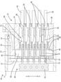
- FIG. 1 is a front sectional view showing a state in which the male side housing and the female side housing are assembled without cutting the male side carrier and the female side carrier.
- FIG. 2 is a normal cross-sectional view showing a state in which the male side carrier and the female side carrier are cut and the male side housing and the female side housing are assembled.
- FIG. 3 is a side sectional view showing a state in which the male side housing and the female side housing are assembled.
- FIG. 4 is a plan sectional view showing a state in which the male side housing and the female side housing are assembled.
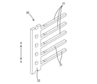
- FIG. 5 is a perspective view of the male terminal fitting.
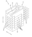
- FIG. 6 is a perspective view of the assembled state of the female connector.
- FIG. 7 is a perspective view of the female terminal fitting.
- FIG. 8 is a perspective view showing a disassembled state of the female side housing.
- the joint connector of the present disclosure is (1) A male terminal fitting having a plurality of tabs parallel to each other in the first arrangement direction and a male carrier capable of connecting the plurality of tabs in parallel and cutting between any adjacent tabs. , A plurality of female side connection portions parallel to the second arrangement direction orthogonal to the first arrangement direction and the plurality of female side connection portions are connected in a parallel state, and any adjacent female side connection portions are connected.
- a female terminal fitting having a female carrier that can be cut between the male terminals is provided, and the plurality of male terminal fittings are arranged so as to be arranged in parallel with the second arrangement direction, and the plurality of female terminal fittings are arranged.
- the female side connecting portions are arranged so as to be arranged in parallel with the first arrangement direction in a state where the plurality of female side connecting portions are connected to the plurality of tabs.
- a male side housing that holds the plurality of male terminal fittings in parallel in the second arrangement direction and a state in which the plurality of female terminal fittings are arranged in parallel in the first arrangement direction. It is preferable to have a female side housing for holding. According to this configuration, a plurality of tabs and a plurality of female side connection portions can be connected by a one-action operation of assembling the male side housing and the female side housing.
- the female side housing has a flat housing structure for holding the female terminal fitting, and a plurality of the housing structures are laminated in the first arrangement direction. Is preferable. According to this configuration, the housing configuration and the female terminal fitting can be shared for a plurality of types of male terminal fittings having different numbers of tabs, so that the number of types of the female side housing and the female terminal fitting can be reduced. ..
- the housing configurations adjacent to each other in the stacking direction are formed with a locking portion that holds the housing configurations in a laminated state by engaging with each other, and the locking portion is formed. It is preferable that they are arranged so as to be point-symmetrical on a virtual plane parallel to both the first arrangement direction and the second arrangement direction. According to this configuration, since the housing configurations can be laminated even in an inverted state, workability when assembling the housing configurations to each other is good.
- the female side connection portion is formed by bending a metal plate material, and the female side carrier brings the female side connection portions adjacent to each other in the second arrangement direction close to each other. It is preferably bent. Since the female-side connecting portion obtained by bending the metal plate has a large area in the unfolded state, there is a concern that the female-side carrier connecting the female-side connecting portions adjacent to each other in the second arrangement direction becomes long. However, by bending the female carrier, the pitch of the female connecting portions adjacent to each other in the second arrangement direction can be narrowed, so that the size can be reduced.
- Example 1 embodying the joint connector of the present disclosure will be described with reference to FIGS. 1 to 8. It should be noted that the present invention is not limited to these examples, and is indicated by the scope of claims, and is intended to include all modifications within the meaning and scope equivalent to the scope of claims.
- the front-back direction is defined as the left side in FIGS. 3 and 4 and the diagonally lower left side in FIGS. 5 to 8 as the front direction.
- the directions appearing in FIGS. 1 to 3, 5 to 8 are defined as upward and downward as they are.
- the directions appearing in FIGS. 1, 2 and 4 are defined as left and right as they are.
- the joint connector of the first embodiment includes one male side connector 10 and a plurality of female side connectors 30 (three in the present embodiment 1).
- the male-side connector 10 includes a male-side housing 11 made of synthetic resin and a plurality of male terminal fittings 20.
- the male side housing 11 has a flat plate-shaped terminal holding portion 12 and a square cylindrical hood portion 13 protruding rearward from the outer peripheral edge of the terminal holding portion 12.
- the terminal holding portion 12 is formed with a plurality of press-fitting holes 15 (15 in the first embodiment) in the form of penetrating the terminal holding portion 12 in the front-rear direction.
- a protruding lock portion 14 is formed on the hood portion 13.
- the plurality of press-fitting holes 15 are arranged so as to be aligned in the first alignment direction X (vertical direction) and the second alignment direction Y (horizontal direction). That is, the plurality of press-fitting holes 15 are divided into five stages in the first arrangement direction X and three rows in the second arrangement direction Y. In each stage, the three press-fitting holes 15 are arranged in a straight line along the second alignment direction Y, and in each row, the five press-fitting holes 15 are arranged in a straight line along the first alignment direction X. Has been done.
- the male terminal fitting 20 is made of a metal plate material punched into a predetermined shape by press working. As shown in FIG. 5, one male terminal fitting 20 is a single component having a plurality of elongated tabs 21 (five in the first embodiment) and one male carrier 22.
- the five tabs 21 are constant in parallel with the first alignment direction X with the length direction oriented in the front-rear direction (direction orthogonal to both the first alignment direction X and the second alignment direction Y). They are arranged in parallel at the pitch.
- the male carrier 22 has an elongated shape in a direction parallel to the first arrangement direction X, and connects the front ends of the five tabs 21 to each other. The male carrier 22 can be cut between any adjacent tabs 21.
- Each male terminal fitting 20 is attached to the male side housing 11 in a direction in which five tabs 21 are arranged in parallel with the first arrangement direction X.
- the five tabs 21 are individually press-fitted into the five press-fitting holes 15 from the front of the male-side housing 11. Since the plurality of press-fitting holes 15 are arranged in three rows on the left and right, the three male terminal fittings 20 are attached to the male side housing 11 in a state of being arranged in parallel in the second arrangement direction Y.
- the female side connector 30 includes one female side housing 31 made of synthetic resin and a plurality of female terminal fittings 50 (five in the first embodiment).
- the female side housing 31 includes one upper housing 32, the same number of housing components 35 as the female terminal fittings 50 (five in the first embodiment), and one lower housing 39. It is composed by assembling.
- the upper housing 32, the housing structure 35, and the lower housing 39 all have a flat shape in which the vertical dimension is smaller than the front-rear dimension and the left-right dimension.
- the female side housing 31 is configured by assembling the upper housing 32, the five housing components 35, and the lower housing 39 in a laminated state in order from the top.
- a lock arm 33 is formed on the upper surface of the upper housing 32.
- an upper accommodating recess 34 is formed on the lower surface of the upper housing 32.
- a locking projection 41 protruding downward is formed on the left side surface of the front end portion of the upper housing 32, and a locking projection 41 projecting downward is formed on the right side surface of the front end portion of the upper housing 32.
- a locking recess 42 is formed. In front view, a locking recess 42 is formed on the left side surface of the rear end portion of the upper housing 32, and a locking projection 41 projecting downward is formed on the right side surface of the rear end portion of the upper housing 32.
- a terminal accommodating chamber 36 is formed inside the housing structure 35.
- the terminal accommodating chamber 36 is open on the upper surface of the housing structure 35.
- On the front wall of the housing structure 35 three insertion openings 37 penetrating from the front surface of the housing structure 35 to the terminal accommodating chamber 36 are formed so as to be arranged in parallel with the second arrangement direction Y.
- a pair of left and right communication holes 38 communicating from the terminal accommodating chamber 36 to the lower surface of the housing structure 35 are formed at the front end portion of the bottom wall portion of the housing structure 35.
- a locking recess 42 and a locking projection 41 projecting downward are formed on the left side surface of the front end portion of the housing structure 35.
- a locking recess 42 and a locking projection 41 projecting upward are formed on the right side surface of the front end portion of the housing structure 35.
- the left and right locking protrusions 41 at the front end of the housing configuration 35 have a point-symmetrical positional relationship in the front view, and the left and right locking recesses 42 at the front end of the housing configuration 35 are also point-symmetric in the front view. It is the positional relationship of.
- a locking recess 42 and a locking projection 41 protruding upward are formed on the left side surface of the rear end portion of the housing structure 35.
- a locking recess 42 and a locking projection 41 protruding downward are formed on the right side surface of the rear end portion of the housing structure 35.
- the left and right locking projections 41 at the rear end of the housing configuration 35 are in a point-symmetrical positional relationship in front view, and the left and right locking recesses 42 at the rear end of the housing configuration 35 are also in front view. It is a point-symmetrical positional relationship.
- a lower accommodating recess 40 is formed so as to penetrate the lower housing 39 in the vertical direction.
- a locking projection 41 projecting upward is formed on the right side surface of the front end portion of the lower housing 39, and the left side surface of the front end portion of the lower housing 39 is formed.
- a locking recess 42 is formed.
- a locking recess 42 is formed on the right side surface of the rear end portion of the lower housing 39, and a locking projection 41 projecting upward is formed on the left side surface of the rear end portion of the lower housing 39.
- the female terminal fitting 50 is formed by bending a metal plate material punched into a predetermined shape by press working.
- One female terminal fitting 50 is a single component having a plurality of female-side connecting portions 51 (three in the first embodiment) and one female-side carrier 52.
- the three female side connecting portions 51 are parallel to the second alignment direction Y with the length direction directed in the front-rear direction (direction orthogonal to both the first alignment direction X and the second alignment direction Y). They are arranged in parallel at a constant pitch.
- An electric wire 53 is connected to the rear end of each female side connecting portion 51.
- the female side carrier 52 is formed by bending an elongated flat plate-shaped portion in a direction parallel to the second arrangement direction Y, and connects the front end portions of the three female side connecting portions 51 to each other.
- the female carrier 52 has a chevron-shaped (inverted V-shaped) shape.
- the female carrier 52 is connected by the female carrier 52 and is adjacent to each other, as compared with the state in which the female carrier 52 is not bent and has a flat plate shape.
- the pitch between 51 is narrow.
- the female carrier 52 can be cut between any adjacent female connecting portions 51.
- Each female terminal fitting 50 is attached to the female side housing 31 in a direction in which three female side connecting portions 51 are arranged in parallel with the second arrangement direction Y.
- One female terminal fitting 50 is attached to one housing structure 35.
- the female side connection portion 51 is housed in the terminal storage chamber 36, and the positional relationship between each female side connection portion 51 and the insertion port 37 facing each other in the front-rear direction.
- the female carrier 52 either protrudes upward from the upper surface of the housing structure 35, or protrudes downward from the communication hole 38 of the housing structure 35.
- the five housing configurations 35 to which the female terminal fittings 50 are attached are stacked one above the other.
- the upper housing 32 is laminated on the upper surface of the uppermost housing structure 35
- the lower housing 39 is laminated on the lower surface of the lowermost housing structure 35.
- the female carrier 52 of the female terminal fitting 50 attached to the housing configuration 35 other than the lowermost stage is in a form of protruding upward, and the female side carrier on the lower stage side is inside the female side carrier 52 on the upper stage side.
- the upper end of 52 is housed.
- the female carrier 52 of the female terminal fitting 50 attached to the uppermost housing structure 35 is accommodated in the upper accommodating recess 34 of the upper housing 32.
- the female carrier 52 of the female terminal fitting 50 attached to the lowermost housing structure 35 is accommodated in the lower accommodating recess 40 of the lower housing 39.
- the laminated housing components 35 are held in a laminated state by locking the locking projection 41 and the locking recess 42.
- the upper housing 32 and the uppermost housing structure 35 are also held in a laminated state by locking the locking projection 41 and the locking recess 42.
- the lowermost housing structure 35 and the lower housing 39 are also held in a laminated state by locking the locking projection 41 and the locking recess 42.
- each female terminal fitting 50 is attached to the female side housing 31 in a direction in which three female side connecting portions 51 are arranged in parallel with the second arrangement direction Y. Since the housing structure 35 holding each female terminal fitting 50 is laminated in five upper and lower stages, the five female terminal fittings 50 are attached to the female side housing 31 in a state of being parallel to the first arrangement direction X. There is.
- the male side connector 10 and the female side connector 30 are assembled by accommodating the female side housing 31 in the hood portion 13.
- the male side housing 11 and the female side housing 31 are locked in the fitted state by locking the lock arm 33 to the lock portion 14 of the hood portion 13. ..
- each tab 21 is inserted into the female side housing 31 from the insertion port 37 and individually connected to the corresponding female side connection portion 51.
- the joint connector of the first embodiment can obtain an arbitrary short-circuit pattern by cutting a part of the male carrier 22 and the female carrier 52.
- the male carrier 22 is cut before the male terminal fitting 20 is attached to the male housing 11.
- the female carrier 52 is also cut before the female terminal fitting 50 is attached to the female housing 31.
- FIG. 2 shows an example of a short circuit pattern.
- the male terminal fitting 20 on the left side since the male side carrier 22 is not cut, the five female side connecting portions 51 on the left side connected to the tab 21 of the male terminal fitting 20 on the left side are short-circuited.
- the female side connection portion 51 on the left side and the female side connection portion 51 in the center are on the female side. Since it is in a state of being connected by the carrier 52, the female side connecting portion 51 in the center in the left-right direction of the second, fourth, and fifth stages from the top is also short-circuited with the five female side connecting portions 51 on the left side. ing.
- the joint connector of the first embodiment has a plurality of male terminal fittings 20 and a plurality of female terminal fittings 50.
- the male terminal fitting 20 has a plurality of tabs 21 parallel to each other in the first arrangement direction X, and a male carrier 22 connecting the plurality of tabs 21 in a parallel state.
- the male carrier 22 can be cut between any adjacent tabs 21.
- the female terminal fitting 50 is a female carrier 52 that connects a plurality of female-side connecting portions 51 parallel to the second alignment direction Y orthogonal to the first alignment direction X and a plurality of female-side connecting portions 51 in a parallel state. And have.
- the female carrier 52 can be cut between any adjacent female connecting portions 51.
- the plurality of male terminal fittings 20 are arranged so as to be arranged in parallel with the second arrangement direction Y.
- the plurality of female terminal fittings are arranged so as to be arranged in parallel with the first arrangement direction X in a state where the plurality of female side connection portions 51 are connected to the plurality of tabs 21.
- a desired short-circuit pattern can be obtained by cutting one or both carriers of the male carrier 22 and the female carrier 52. Even if the number of types of short-circuit patterns increases, the number of types of parts does not increase because the male terminal fitting 20 and the female terminal fitting 50 can be shared. Therefore, according to the joint connector of the first embodiment, it is possible to suppress an increase in cost even if the short circuit pattern increases.
- the joint connector has a male side housing 11 that holds a plurality of male terminal fittings 20 in a state of being arranged in parallel in the second arrangement direction Y.
- the joint connector has a female side housing 31 that holds a plurality of female terminal fittings 50 in a state of being arranged in parallel in the first arrangement direction X. According to this configuration, a plurality of tabs 21 and a plurality of female side connecting portions 51 can be connected by a one-action operation of assembling the male side housing 11 and the female side housing 31.
- the female side housing 31 has a flat housing structure 35 that holds the female terminal fitting 50.
- the plurality of housing components 35 are laminated in the first arrangement direction X. According to this configuration, the housing configuration 35 and the female terminal fitting 50 can be shared with respect to a plurality of types of male terminal fittings 20 having different numbers of tabs 21, so that the female side housing 31 and the female terminal fitting 50 can be shared. The number of types is small.
- the housing components 35 adjacent to each other in the stacking direction are formed with a locking projection 41 and a locking recess 42 as locking portions for holding the housing components 35 in a stacked state by engaging with each other.
- the locking projections 41 are arranged so as to be point-symmetrical on a virtual plane parallel to both the first alignment direction X and the second alignment direction Y, that is, when the female side housing 31 is viewed from the front. ing. According to this configuration, since the housing components 35 can be laminated even in an inverted state, workability when assembling the housing components 35 to each other is good.
- the female side connection portion 51 is formed by bending a metal plate material. Since the female side connecting portion 51 obtained by bending the metal plate material has a large area in the expanded state, the female side carrier 52 connecting the female side connecting portions 51 adjacent to each other in the second arrangement direction Y becomes long, and the adjacent female side connecting portions 51 are connected. There is a concern that the pitch of the portion 51 will increase.
- the female-side carrier 52 of the joint connector of the first embodiment is bent so as to bring the female-side connecting portions 51 adjacent to each other in the second arrangement direction Y close to each other. Therefore, the pitch of the female side connecting portions 51 adjacent to each other in the second arrangement direction Y can be narrowed to reduce the size.
- the present invention is not limited to the embodiments described above and in the drawings, but is shown by the scope of claims.
- the present invention includes the meaning equivalent to the scope of claims and all modifications within the scope of claims, and is intended to include embodiments such as the following.
- a plurality of male terminal fittings are held in the male side housing and a plurality of female terminal fittings are held in the female side housing, but a plurality of male terminal fittings and a plurality of female terminal fittings are held in one housing. You may hold it.
- the female side housing is configured by laminating a plurality of housing components, but the female side housing may be a single component.
- the locking portion that holds the housing components in a laminated state is in a point-symmetrical form, but the locking portion may be in a non-point-symmetrical form.
- the female side carrier is bent into a V shape, but the bent shape of the female side carrier may be a U shape, an S shape, an N shape, or the like.
Landscapes
- Connector Housings Or Holding Contact Members (AREA)
- Coupling Device And Connection With Printed Circuit (AREA)
Abstract
短絡パターンが増えてもコストの上昇を抑える。 ジョイントコネクタは、第1の並び方向に並列する複数のタブ(21)と、複数のタブ(21)を並列状態で連結し、隣り合う任意のタブ(21)の間において切断が可能な雄側キャリア(22)とを有する雄端子金具(20)と、第1の並び方向と直交する第2の並び方向に並列する複数の雌側接続部(51)と、複数の雌側接続部(51)を並列状態で連結し、隣り合う任意の雌側接続部(51)の間において切断が可能な雌側キャリア(52)とを有する雌端子金具(50)とを備え、複数の雄端子金具(20)が第2の並び方向と平行に並ぶように配置され、複数の雌側端子金具(50)が、複数の雌側接続部(51)を複数のタブ(21)に接続した状態で第1の並び方向と平行に並ぶように配置されている。
Description
本開示は、ジョイントコネクタに関するものである。
特許文献1には、プリント回路基板に、複数本のオス端子をマトリックス状に配置して立設し、プリント回路基板に形成した回路パターンによって、所望のオス端子同士を短絡させる構造のジョイントコネクタが開示されている。
このジョイントコネクタは、オス端子同士の短絡パターンが異なる毎に、その短絡パターンと同じ回路パターンを有するプリント回路基板を用意する必要がある。即ち、オス端子の短絡パターンの種類数が増えると、その分、プリント回路基板の種類数が増大する。プリント回路基板は比較的高価な部品である。そのため、短絡パターンが増えるほど、必要なプリント回路基板の種類数も増えるので、コストが高くなっていく。
本開示のジョイントコネクタは、上記のような事情に基づいて完成されたものであって、短絡パターンが増えてもコストの上昇を抑えることを目的とする。
本開示のジョイントコネクタは、
第1の並び方向に並列する複数のタブと、前記複数のタブを並列状態で連結し、隣り合う任意の前記タブの間において切断が可能な雄側キャリアとを有する雄端子金具と、
前記第1の並び方向と直交する第2の並び方向に並列する複数の雌側接続部と、前記複数の雌側接続部を並列状態で連結し、隣り合う任意の前記雌側接続部の間において切断が可能な雌側キャリアとを有する雌端子金具とを備え、
複数の前記雄端子金具が前記第2の並び方向と平行に並ぶように配置され、
複数の前記雌側端子金具が、複数の前記雌側接続部を複数の前記タブに接続した状態で前記第1の並び方向と平行に並ぶように配置されている。
第1の並び方向に並列する複数のタブと、前記複数のタブを並列状態で連結し、隣り合う任意の前記タブの間において切断が可能な雄側キャリアとを有する雄端子金具と、
前記第1の並び方向と直交する第2の並び方向に並列する複数の雌側接続部と、前記複数の雌側接続部を並列状態で連結し、隣り合う任意の前記雌側接続部の間において切断が可能な雌側キャリアとを有する雌端子金具とを備え、
複数の前記雄端子金具が前記第2の並び方向と平行に並ぶように配置され、
複数の前記雌側端子金具が、複数の前記雌側接続部を複数の前記タブに接続した状態で前記第1の並び方向と平行に並ぶように配置されている。
本開示によれば、短絡パターンが増えてもコストの上昇を抑えることかできる。
[本開示の実施形態の説明]
最初に本開示の実施形態を列記して説明する。
本開示のジョイントコネクタは、
(1)第1の並び方向に並列する複数のタブと、前記複数のタブを並列状態で連結し、隣り合う任意の前記タブの間において切断が可能な雄側キャリアとを有する雄端子金具と、前記第1の並び方向と直交する第2の並び方向に並列する複数の雌側接続部と、前記複数の雌側接続部を並列状態で連結し、隣り合う任意の前記雌側接続部の間において切断が可能な雌側キャリアとを有する雌端子金具とを備え、複数の前記雄端子金具が前記第2の並び方向と平行に並ぶように配置され、複数の前記雌側端子金具が、複数の前記雌側接続部を複数の前記タブに接続した状態で前記第1の並び方向と平行に並ぶように配置されている。本開示の構成によれば、雄側キャリアと雌側キャリアのうち一方又は両方のキャリアを切断することによって、所望の短絡パターンを得ることができる。短絡パターンの種類数が増えても、雄端子金具と雌端子金具を共用できるので、部品の種類数が増えることがない。したがって、本開示によれば、短絡パターンが増えてもコストの上昇を抑えることができる。
最初に本開示の実施形態を列記して説明する。
本開示のジョイントコネクタは、
(1)第1の並び方向に並列する複数のタブと、前記複数のタブを並列状態で連結し、隣り合う任意の前記タブの間において切断が可能な雄側キャリアとを有する雄端子金具と、前記第1の並び方向と直交する第2の並び方向に並列する複数の雌側接続部と、前記複数の雌側接続部を並列状態で連結し、隣り合う任意の前記雌側接続部の間において切断が可能な雌側キャリアとを有する雌端子金具とを備え、複数の前記雄端子金具が前記第2の並び方向と平行に並ぶように配置され、複数の前記雌側端子金具が、複数の前記雌側接続部を複数の前記タブに接続した状態で前記第1の並び方向と平行に並ぶように配置されている。本開示の構成によれば、雄側キャリアと雌側キャリアのうち一方又は両方のキャリアを切断することによって、所望の短絡パターンを得ることができる。短絡パターンの種類数が増えても、雄端子金具と雌端子金具を共用できるので、部品の種類数が増えることがない。したがって、本開示によれば、短絡パターンが増えてもコストの上昇を抑えることができる。
(2)前記複数の雄端子金具を、前記第2の並び方向に並列させた状態で保持する雄側ハウジングと、前記複数の雌端子金具を、前記第1の並び方向に並列させた状態で保持する雌側ハウジングとを備えていることが好ましい。この構成によれば、雄側ハウジングと雌側ハウジングを組み付けるというワンアクションの作業によって、複数のタブと複数の雌側接続部を接続させることができる。
(3)(2)において、前記雌側ハウジングは、前記雌端子金具を保持する偏平形状のハウジング構成体を有し、複数の前記ハウジング構成体が、前記第1の並び方向に積層されていることが好ましい。この構成によれば、タブの数が異なる複数種類の雄端子金具に対して、ハウジング構成体と雌端子金具を共用することができるので、雌側ハウジングと雌端子金具の種類数が少なくて済む。
(4)(3)において、積層方向に隣接する前記ハウジング構成体には、互いに係止することによって前記ハウジング構成体同士を積層状態に保持する係止部が形成され、前記係止部が、前記第1の並び方向及び前記第2の並び方向の両方向と平行な仮想平面上において、点対称となるように配置されていることが好ましい。この構成によれば、ハウジング構成体を反転させた状態でも積層することができるので、ハウジング構成体同士を組み付ける際の作業性が良い。
(5)前記雌側接続部は、金属板材を曲げ加工して成形されたものであり、前記雌側キャリアは、前記第2の並び方向に隣り合う前記雌側接続部同士を接近させるように屈曲されていることが好ましい。金属板材を曲げ加工した雌側接続部は展開状態の面積が大きいので、第2の並び方向に隣り合う雌側接続部を連結する雌側キャリアが長くなることが懸念される。しかし、雌側キャリアを屈曲させることによって、第2の並び方向に隣り合う雌側接続部のピッチを狭めることができるので、小型化を図ることが可能である。
[本開示の実施形態の詳細]
[実施例1]
本開示のジョイントコネクタを具体化した実施例1を、図1~図8を参照して説明する。なお、本発明はこれらの例示に限定されるものではなく、特許請求の範囲によって示され、特許請求の範囲と均等の意味および範囲内でのすべての変更が含まれることが意図される。本実施例1において、前後の方向については、図3,4における左方、及び図5~8における斜め左下方を前方と定義する。上下の方向については、図1~3,5~8にあらわれる向きを、そのまま上方、下方と定義する。左右の方向については、図1,2,4にあらわれる向きを、そのまま左方、右方と定義する。
[実施例1]
本開示のジョイントコネクタを具体化した実施例1を、図1~図8を参照して説明する。なお、本発明はこれらの例示に限定されるものではなく、特許請求の範囲によって示され、特許請求の範囲と均等の意味および範囲内でのすべての変更が含まれることが意図される。本実施例1において、前後の方向については、図3,4における左方、及び図5~8における斜め左下方を前方と定義する。上下の方向については、図1~3,5~8にあらわれる向きを、そのまま上方、下方と定義する。左右の方向については、図1,2,4にあらわれる向きを、そのまま左方、右方と定義する。
本実施例1のジョイントコネクタは、1つの雄側コネクタ10と、複数(本実施例1では3つ)の雌側コネクタ30とを備えている。雄側コネクタ10は、合成樹脂製の雄側ハウジング11と、複数の雄端子金具20とを備えている。図3,4に示すように、雄側ハウジング11は、平板状の端子保持部12と、端子保持部12の外周縁から後方へ突出した角筒状のフード部13とを有する。端子保持部12には、端子保持部12を前後方向に貫通した形態の複数(本実施例1では15)の圧入孔15が形成されている。フード部13には、突起状のロック部14が形成されている。
複数の圧入孔15は、第1の並び方向X(上下方向)及び第2の並び方向Y(左右方向)において整列するように配置されている。つまり、複数の圧入孔15は、第1の並び方向Xにおいて5段に分かれているとともに、第2の並び方向Yにおいて3列に分かれている。各段においては、3つの圧入孔15が第2の並び方向Yに沿って一直線状に配置され、各列においては、5つの圧入孔15が第1の並び方向Xに沿って一直線状に配置されている。
雄端子金具20は、プレス加工によって所定形状に打ち抜いた金属板材からなる。図5に示すように、1つの雄端子金具20は、複数本(本実施例1では5本)の細長いタブ21と、1本の雄側キャリア22とを有する単一部品である。5本のタブ21は、長さ方向を前後方向(第1の並び方向X及び第2の並び方向Yの両方向に対して直交する方向)に向けて、第1の並び方向Xと平行に一定ピッチで並列するように配置されている。雄側キャリア22は、第1の並び方向Xと平行な方向に細長い形状であり、5本のタブ21の前端部同士を連結している。雄側キャリア22は、隣り合う任意のタブ21同士の間において切断することが可能である。
各雄端子金具20は、雄側ハウジング11に対し、5本のタブ21が第1の並び方向Xと平行に並ぶ向きで取り付けられている。雄端子金具20を取り付ける際には、5つのタブ21が、雄側ハウジング11の前方から5つの圧入孔15に個別に圧入される。複数の圧入孔15は、左右3列に分かれて整列されているので、3つの雄端子金具20が第2の並び方向Yに並列した状態で雄側ハウジング11に取り付けられている。
雌側コネクタ30は、合成樹脂製の1つの雌側ハウジング31と、複数(本実施例1では5つ)の雌端子金具50とを備えている。図6,8に示すように、雌側ハウジング31は、1つのアッパハウジング32と、雌端子金具50と同数(本実施例1では5つ)のハウジング構成体35と、1つのロアハウジング39とを組み付けて構成されている。アッパハウジング32とハウジング構成体35とロアハウジング39は、いずれも、前後方向の寸法及び左右方向の寸法に対して、上下方向の寸法が小さい偏平な形状をなす。アッパハウジング32と5つのハウジング構成体35とロアハウジング39を、上から順に積層した状態で組み付けることによって、雌側ハウジング31が構成されている。
アッパハウジング32の上面にはロックアーム33が形成されている。図1,3に示すように、アッパハウジング32の下面には、上側収容凹部34が形成されている。アッパハウジング32(雌側ハウジング31)を前方から見た正面視において、アッパハウジング32の前端部左側面には下方へ突出する係止突起41が形成され、アッパハウジング32の前端部右側面には係止凹部42が形成されている。正面視において、アッパハウジング32の後端部左側面には係止凹部42が形成され、アッパハウジング32の後端部右側面には下方へ突出する係止突起41が形成されている。
ハウジング構成体35の内部には、端子収容室36が形成されている。端子収容室36は、ハウジング構成体35の上面に開口している。ハウジング構成体35の前面壁には、ハウジング構成体35の前面から端子収容室36へ貫通する3つの挿入口37が、第2の並び方向Yと平行に並ぶように形成されている。ハウジング構成体35の底壁部における前端部には、端子収容室36からハウジング構成体35の下面に連通する左右一対の連通孔38が形成されている。
ハウジング構成体35(雌側ハウジング31)を前方から見た正面視において、ハウジング構成体35の前端部左側面には、係止凹部42と、下方へ突出する係止突起41とが形成されている。正面視において、ハウジング構成体35の前端部右側面には、係止凹部42と、上方へ突出する係止突起41が形成されている。ハウジング構成体35の前端部の左右両係止突起41同士は、正面視において点対称の位置関係であり、ハウジング構成体35の前端部の左右両係止凹部42同士も、正面視において点対称の位置関係である。
正面視において、ハウジング構成体35の後端部左側面には、係止凹部42と、上方へ突出する係止突起41とが形成されている。正面視において、ハウジング構成体35の後端部右側面には、係止凹部42と、下方へ突出する係止突起41が形成されている。ハウジング構成体35の後端部の左右両係止突起41同士は、正面視において点対称の位置関係であり、ハウジング構成体35の後端部の左右両係止凹部42同士も、正面視において点対称の位置関係である。
ロアハウジング39の前端部には、ロアハウジング39を上下方向に貫通した形態の下側収容凹部40が形成されている。ロアハウジング39(雌側ハウジング31)を前方から見た正面視において、ロアハウジング39の前端部右側面には上方へ突出する係止突起41が形成され、ロアハウジング39の前端部左側面には係止凹部42が形成されている。正面視において、ロアハウジング39の後端部右側面には係止凹部42が形成され、ロアハウジング39の後端部左側面には上方へ突出する係止突起41が形成されている。
雌端子金具50は、プレス加工によって所定形状に打ち抜いた金属板材に曲げ加工等を施して成形したものである。1つの雌端子金具50は、複数本(本実施例1では3つ)の雌側接続部51と、1本の雌側キャリア52とを有する単一部品である。3つの雌側接続部51は、長さ方向を前後方向(第1の並び方向X及び第2の並び方向Yの両方向に対して直交する方向)に向けて、第2の並び方向Yと平行に一定ピッチで並列するように配置されている。各雌側接続部51の後端部には、電線53が接続されている。
雌側キャリア52は、第2の並び方向Yと平行な方向に細長い平板状の部位を曲げ加工して形成したものであり、3つの雌側接続部51の前端部同士を連結している。正面視において、雌側キャリア52は、山形(逆V字形)に屈曲した形状である。雌側キャリア52を山形に屈曲した形状に成形することにより、雌側キャリア52が屈曲されずに平板状をなしている状態と比較すると、雌側キャリア52で連結されて隣り合う雌側接続部51同士のピッチが狭くなっている。雌側キャリア52は、隣り合う任意の雌側接続部51同士の間において切断することが可能である。
各雌端子金具50は、雌側ハウジング31に対し、3つの雌側接続部51が第2の並び方向Yと平行に並ぶ向きで取り付けられている。1つの雌端子金具50は1つのハウジング構成体35に取り付けられる。雌端子金具50をハウジング構成体35に取り付けた状態では、雌側接続部51が端子収容室36内に収容され、各雌側接続部51と挿入口37とが前後方向に対向する位置関係となる。雌側キャリア52は、ハウジング構成体35の上面よりも上方へ突出した形態か、連通孔38からハウジング構成体35の下方へ突出した形態となる。
雌端子金具50が取り付けられた5つのハウジング構成体35は、上下に積層される。最上段のハウジング構成体35の上面には、アッパハウジング32が積層され、最下段のハウジング構成体35の下面にはロアハウジング39が積層される。最下段以外のハウジング構成体35に取り付けた雌端子金具50の雌側キャリア52は、いずれも、上向きに突出する形態であり、上段側の雌側キャリア52の内側に、下段側の雌側キャリア52の上端部が収容される。最上段のハウジング構成体35に取り付けた雌端子金具50の雌側キャリア52は、アッパハウジング32の上側収容凹部34内に収容される。最下段のハウジング構成体35に取り付けた雌端子金具50の雌側キャリア52は、ロアハウジング39の下側収容凹部40内に収容される。
積層したハウジング構成体35同士は、係止突起41と係止凹部42との係止によって積層状態に保持される。アッパハウジング32と最上段のハウジング構成体35も、係止突起41と係止凹部42との係止によって積層状態に保持される。最下段のハウジング構成体35とロアハウジング39も、係止突起41と係止凹部42との係止によって積層状態に保持される。
以上により、雌側ハウジング31が組み付けられると同時に、雌側ハウジング31に3つの雌端子金具50が取り付けられる。各雌端子金具50は、雌側ハウジング31に対し、3つの雌側接続部51が第2の並び方向Yと平行に並ぶ向きで取り付けられている。各雌端子金具50を保持するハウジング構成体35は、上下5段に積層されているので、5つの雌端子金具50が第1の並び方向Xに並列した状態で雌側ハウジング31に取り付けられている。
雄側コネクタ10と雌側コネクタ30は、雌側ハウジング31をフード部13に収容することによって組み付けられている。雄側コネクタ10と雌側コネクタ30を組み付けた状態では、ロックアーム33がフード部13のロック部14に係止することによって、雄側ハウジング11と雌側ハウジング31が嵌合状態にロックされる。両コネクタ10,30を組み付けた状態では、各タブ21が、挿入口37から雌側ハウジング31内に挿入され、対応する雌側接続部51に個別に接続される。
本実施例1のジョイントコネクタは、雄側キャリア22と雌側キャリア52の一部を切断することによって、任意の短絡パターンを得ることができる。雄側キャリア22の切断は、雄端子金具20を雄側ハウジング11に取り付ける前に行っておく。雌側キャリア52の切断も、雌端子金具50を雌側ハウジング31に取り付ける前に行っておく。
図2には、短絡パターンの一例を示す。左側の雄端子金具20は、雄側キャリア22が切断されていないため、この左側の雄端子金具20のタブ21に接続された左側の5つの雌側接続部51が短絡している。また、上から2段目と4段目と5段目のハウジング構成体35に取り付けられた3つの雌端子金具50は、左側の雌側接続部51と中央の雌側接続部51が雌側キャリア52で接続された状態となっているので、上から2段目と4段目と5段目の左右方向中央の雌側接続部51も、左側の5つの雌側接続部51と短絡している。
本実施例1のジョイントコネクタは、複数の雄端子金具20と複数の雌端子金具50を有する。雄端子金具20は、第1の並び方向Xに並列する複数のタブ21と、複数のタブ21を並列状態で連結する雄側キャリア22とを有する。雄側キャリア22は、隣り合う任意のタブ21の間において切断が可能である。雌端子金具50は、第1の並び方向Xと直交する第2の並び方向Yに並列する複数の雌側接続部51と、複数の雌側接続部51を並列状態で連結する雌側キャリア52とを有する。雌側キャリア52は、隣り合う任意の雌側接続部51の間において切断が可能である。複数の雄端子金具20は第2の並び方向Yと平行に並ぶように配置されている。複数の雌側端子金具は、複数の雌側接続部51を複数のタブ21に接続した状態で、第1の並び方向Xと平行に並ぶように配置されている。
この構成によれば、雄側キャリア22と雌側キャリア52のうち一方又は両方のキャリアを切断することによって、所望の短絡パターンを得ることができる。短絡パターンの種類数が増えても、雄端子金具20と雌端子金具50を共用できるので、部品の種類数が増えることがない。したがって、本実施例1のジョイントコネクタによれば、短絡パターンが増えてもコストの上昇を抑えることができる。
ジョイントコネクタは、複数の雄端子金具20を、第2の並び方向Yに並列させた状態で保持する雄側ハウジング11を有する。ジョイントコネクタは、複数の雌端子金具50を、第1の並び方向Xに並列させた状態で保持する雌側ハウジング31を有する。この構成によれば、雄側ハウジング11と雌側ハウジング31を組み付けるというワンアクションの作業によって、複数のタブ21と複数の雌側接続部51を接続させることができる。
雌側ハウジング31は、前記雌端子金具50を保持する偏平形状のハウジング構成体35を有する。複数のハウジング構成体35は、第1の並び方向Xに積層されている。この構成によれば、タブ21の数が異なる複数種類の雄端子金具20に対して、ハウジング構成体35と雌端子金具50を共用することができるので、雌側ハウジング31と雌端子金具50の種類数が少なくて済む。
積層方向に隣接するハウジング構成体35には、互いに係止することによってハウジング構成体35同士を積層状態に保持する係止部としての係止突起41と係止凹部42が形成されている。係止突起41は、第1の並び方向X及び第2の並び方向Yの両方向と平行な仮想平面上、つまり雌側ハウジング31を前方から見た正面視において、点対称となるように配置されている。この構成によれば、ハウジング構成体35を反転させた状態でも積層することができるので、ハウジング構成体35同士を組み付ける際の作業性が良い。
雌側接続部51は、金属板材を曲げ加工して成形されたものである。金属板材を曲げ加工した雌側接続部51は展開状態の面積が大きいので、第2の並び方向Yに隣り合う雌側接続部51を連結する雌側キャリア52が長くなり、隣り合う雌側接続部51のピッチが大きくなることが懸念される。本実施例1のジョイントコネクタの雌側キャリア52は、第2の並び方向Yに隣り合う雌側接続部51同士を接近させるように屈曲させている。したがって、第2の並び方向Yに隣り合う雌側接続部51のピッチを狭めて、小型化を図ることができる。
[他の実施例]
本発明は、上記記述及び図面によって説明した実施例に限定されるものではなく、特許請求の範囲によって示される。本発明には、特許請求の範囲と均等の意味及び特許請求の範囲内でのすべての変更が含まれ、下記のような実施形態も含まれることが意図される。
上記実施例1では、複数の雄端子金具を雄側ハウジングに保持し、複数の雌端子金具を雌側ハウジングに保持したが、1つのハウジングに、複数の雄端子金具と複数の雌端子金具を保持してもよい。
上記実施例1では、雌側ハウジングが複数のハウジング構成体を積層して構成されているが、雌側ハウジングは単一の部品であってもよい。
上記実施例1では、ハウジング構成体同士を積層状態に保持する係止部が、点対称な形態であるが、係止部は点対称ではない形態であってもよい。
上記実施例1では、雌側キャリアがV字形に屈曲した形状であるが、雌側キャリアの屈曲形状は、U字形、S字形、N字形等であってもよい。
本発明は、上記記述及び図面によって説明した実施例に限定されるものではなく、特許請求の範囲によって示される。本発明には、特許請求の範囲と均等の意味及び特許請求の範囲内でのすべての変更が含まれ、下記のような実施形態も含まれることが意図される。
上記実施例1では、複数の雄端子金具を雄側ハウジングに保持し、複数の雌端子金具を雌側ハウジングに保持したが、1つのハウジングに、複数の雄端子金具と複数の雌端子金具を保持してもよい。
上記実施例1では、雌側ハウジングが複数のハウジング構成体を積層して構成されているが、雌側ハウジングは単一の部品であってもよい。
上記実施例1では、ハウジング構成体同士を積層状態に保持する係止部が、点対称な形態であるが、係止部は点対称ではない形態であってもよい。
上記実施例1では、雌側キャリアがV字形に屈曲した形状であるが、雌側キャリアの屈曲形状は、U字形、S字形、N字形等であってもよい。
10…雄側コネクタ
11…雄側ハウジング
12…端子保持部
13…フード部
14…ロック部
15…圧入孔
20…雄端子金具
21…タブ
22…雄側キャリア
30…雌側コネクタ
31…雌側ハウジング
32…アッパハウジング
33…ロックアーム
34…上側収容凹部
35…ハウジング構成体
36…端子収容室
37…挿入口
38…連通孔
39…ロアハウジング
40…下側収容凹部
41…係止突起
42…係止凹部
50…雌端子金具
51…雌側接続部
52…雌側キャリア
53…電線
X…第1の並び方向
Y…第2の並び方向
11…雄側ハウジング
12…端子保持部
13…フード部
14…ロック部
15…圧入孔
20…雄端子金具
21…タブ
22…雄側キャリア
30…雌側コネクタ
31…雌側ハウジング
32…アッパハウジング
33…ロックアーム
34…上側収容凹部
35…ハウジング構成体
36…端子収容室
37…挿入口
38…連通孔
39…ロアハウジング
40…下側収容凹部
41…係止突起
42…係止凹部
50…雌端子金具
51…雌側接続部
52…雌側キャリア
53…電線
X…第1の並び方向
Y…第2の並び方向
Claims (5)
- 第1の並び方向に並列する複数のタブと、前記複数のタブを並列状態で連結し、隣り合う任意の前記タブの間において切断が可能な雄側キャリアとを有する雄端子金具と、
前記第1の並び方向と直交する第2の並び方向に並列する複数の雌側接続部と、前記複数の雌側接続部を並列状態で連結し、隣り合う任意の前記雌側接続部の間において切断が可能な雌側キャリアとを有する雌端子金具とを備え、
複数の前記雄端子金具が前記第2の並び方向と平行に並ぶように配置され、
複数の前記雌側端子金具が、複数の前記雌側接続部を複数の前記タブに接続した状態で前記第1の並び方向と平行に並ぶように配置されているジョイントコネクタ。 - 前記複数の雄端子金具を、前記第2の並び方向に並列させた状態で保持する雄側ハウジングと、
前記複数の雌端子金具を、前記第1の並び方向に並列させた状態で保持する雌側ハウジングとを備えている請求項1に記載のジョイントコネクタ。 - 前記雌側ハウジングは、前記雌端子金具を保持する偏平形状のハウジング構成体を有し、
複数の前記ハウジング構成体が、前記第1の並び方向に積層されている請求項2に記載のジョイントコネクタ。 - 積層方向に隣接する前記ハウジング構成体には、互いに係止することによって前記ハウジング構成体同士を積層状態に保持する係止部が形成され、
前記係止部が、前記第1の並び方向及び前記第2の並び方向の両方向と平行な仮想平面上において、点対称となるように配置されている請求項3に記載のジョイントコネクタ。 - 前記雌側接続部は、金属板材を曲げ加工して成形されたものであり、
前記雌側キャリアは、前記第2の並び方向に隣り合う前記雌側接続部同士を接近させるように屈曲されている請求項1から請求項4のいずれか1項に記載のジョイントコネクタ。
Priority Applications (2)
| Application Number | Priority Date | Filing Date | Title |
|---|---|---|---|
| US18/021,515 US20230299536A1 (en) | 2020-08-31 | 2021-07-29 | Joint connector |
| CN202180056271.7A CN116075988A (zh) | 2020-08-31 | 2021-07-29 | 接头连接器 |
Applications Claiming Priority (2)
| Application Number | Priority Date | Filing Date | Title |
|---|---|---|---|
| JP2020-145163 | 2020-08-31 | ||
| JP2020145163A JP7417201B2 (ja) | 2020-08-31 | 2020-08-31 | ジョイントコネクタ |
Publications (1)
| Publication Number | Publication Date |
|---|---|
| WO2022044690A1 true WO2022044690A1 (ja) | 2022-03-03 |
Family
ID=80353092
Family Applications (1)
| Application Number | Title | Priority Date | Filing Date |
|---|---|---|---|
| PCT/JP2021/028216 Ceased WO2022044690A1 (ja) | 2020-08-31 | 2021-07-29 | ジョイントコネクタ |
Country Status (4)
| Country | Link |
|---|---|
| US (1) | US20230299536A1 (ja) |
| JP (1) | JP7417201B2 (ja) |
| CN (1) | CN116075988A (ja) |
| WO (1) | WO2022044690A1 (ja) |
Citations (5)
| Publication number | Priority date | Publication date | Assignee | Title |
|---|---|---|---|---|
| JP2000150055A (ja) * | 1998-11-13 | 2000-05-30 | Yazaki Corp | ジョイントコネクタ |
| JP2003346968A (ja) * | 2002-05-29 | 2003-12-05 | Sumitomo Wiring Syst Ltd | 分割コネクタ |
| JP2004031178A (ja) * | 2002-06-27 | 2004-01-29 | Furukawa Electric Co Ltd:The | 積層型ジョイントコネクタ |
| WO2016170958A1 (ja) * | 2015-04-23 | 2016-10-27 | 株式会社オートネットワーク技術研究所 | ジョイントコネクタ |
| WO2016208369A1 (ja) * | 2015-06-22 | 2016-12-29 | 株式会社オートネットワーク技術研究所 | 複合コネクタ及びその製造方法 |
Family Cites Families (10)
| Publication number | Priority date | Publication date | Assignee | Title |
|---|---|---|---|---|
| US4021095A (en) * | 1974-02-21 | 1977-05-03 | Amp Incorporated | Stacked carrier strip assembly |
| US5175928A (en) * | 1990-06-11 | 1993-01-05 | Amp Incorporated | Method of manufacturing an electrical connection assembly |
| DE19523793C1 (de) * | 1995-06-29 | 1996-11-07 | Siemens Ag | An Datenbus betreibbarer stapelbarer Datenträger |
| JP2000173689A (ja) * | 1998-12-07 | 2000-06-23 | Yazaki Corp | ジョイントコネクタ及びジョイントコネクタ用接続端子金具の製造方法 |
| JP3459375B2 (ja) * | 1999-04-06 | 2003-10-20 | 矢崎総業株式会社 | 圧接ジョイントコネクタ |
| JP3638840B2 (ja) * | 1999-12-02 | 2005-04-13 | 矢崎総業株式会社 | コネクタの接続方法 |
| JP3754304B2 (ja) * | 2001-02-16 | 2006-03-08 | 矢崎総業株式会社 | ジョイントコネクタ |
| US7837522B1 (en) * | 2009-11-12 | 2010-11-23 | Samtec, Inc. | Electrical contacts with solder members and methods of attaching solder members to electrical contacts |
| CN112993630B (zh) * | 2019-12-13 | 2022-06-24 | 富士康(昆山)电脑接插件有限公司 | 电连接器 |
| DE102021111935B3 (de) * | 2021-05-07 | 2022-04-21 | Lumberg Connect Gmbh | Steckkontakt |
-
2020
- 2020-08-31 JP JP2020145163A patent/JP7417201B2/ja active Active
-
2021
- 2021-07-29 WO PCT/JP2021/028216 patent/WO2022044690A1/ja not_active Ceased
- 2021-07-29 CN CN202180056271.7A patent/CN116075988A/zh active Pending
- 2021-07-29 US US18/021,515 patent/US20230299536A1/en not_active Abandoned
Patent Citations (5)
| Publication number | Priority date | Publication date | Assignee | Title |
|---|---|---|---|---|
| JP2000150055A (ja) * | 1998-11-13 | 2000-05-30 | Yazaki Corp | ジョイントコネクタ |
| JP2003346968A (ja) * | 2002-05-29 | 2003-12-05 | Sumitomo Wiring Syst Ltd | 分割コネクタ |
| JP2004031178A (ja) * | 2002-06-27 | 2004-01-29 | Furukawa Electric Co Ltd:The | 積層型ジョイントコネクタ |
| WO2016170958A1 (ja) * | 2015-04-23 | 2016-10-27 | 株式会社オートネットワーク技術研究所 | ジョイントコネクタ |
| WO2016208369A1 (ja) * | 2015-06-22 | 2016-12-29 | 株式会社オートネットワーク技術研究所 | 複合コネクタ及びその製造方法 |
Also Published As
| Publication number | Publication date |
|---|---|
| CN116075988A (zh) | 2023-05-05 |
| JP7417201B2 (ja) | 2024-01-18 |
| US20230299536A1 (en) | 2023-09-21 |
| JP2022040439A (ja) | 2022-03-11 |
Similar Documents
| Publication | Publication Date | Title |
|---|---|---|
| US12237613B2 (en) | Printed circuit board plug connector | |
| CN102176557B (zh) | 高密度底板连接器 | |
| US8308513B2 (en) | Electrical connector | |
| US20080194140A1 (en) | Modular jack assembly | |
| US8944829B2 (en) | Connector | |
| TWI715774B (zh) | 表面安裝型連接器 | |
| US7153145B2 (en) | Electric junction box and connection structure of tuning fork terminal | |
| US12489241B2 (en) | Connection strip and method of manufacturing the connection strip | |
| JPH1032060A (ja) | モジュール形コネクタ | |
| JP4828626B2 (ja) | コネクタ | |
| JP4391310B2 (ja) | 多極コネクタ及びその組立方法 | |
| JP2013089474A (ja) | 組立体 | |
| WO2022044690A1 (ja) | ジョイントコネクタ | |
| JP2009520325A (ja) | 電気コネクタ組立体及びその製造方法 | |
| JP7541050B2 (ja) | 電子部品モジュール | |
| US5971785A (en) | Hermaphroditic connector for printed circuit boards | |
| US7300290B2 (en) | Electrical connector | |
| JP7468457B2 (ja) | フレキシブルケーブル用コネクタ | |
| JP7248453B2 (ja) | ジョイントコネクタ | |
| JP2006269107A (ja) | コネクタ | |
| CN110168819B (zh) | 接头连接器 | |
| TWI867983B (zh) | 模組連接器以及連接器組件 | |
| US20230361496A1 (en) | Electrical assembly and header | |
| JP4727464B2 (ja) | ジョイントコネクタ | |
| JP4286772B2 (ja) | ジャンクションブロック |
Legal Events
| Date | Code | Title | Description |
|---|---|---|---|
| 121 | Ep: the epo has been informed by wipo that ep was designated in this application |
Ref document number: 21861118 Country of ref document: EP Kind code of ref document: A1 |
|
| DPE1 | Request for preliminary examination filed after expiration of 19th month from priority date (pct application filed from 20040101) | ||
| NENP | Non-entry into the national phase |
Ref country code: DE |
|
| 122 | Ep: pct application non-entry in european phase |
Ref document number: 21861118 Country of ref document: EP Kind code of ref document: A1 |