WO2022044601A1 - 建設機械の作業制御方法、作業制御システム及び作業制御装置 - Google Patents
建設機械の作業制御方法、作業制御システム及び作業制御装置 Download PDFInfo
- Publication number
- WO2022044601A1 WO2022044601A1 PCT/JP2021/026600 JP2021026600W WO2022044601A1 WO 2022044601 A1 WO2022044601 A1 WO 2022044601A1 JP 2021026600 W JP2021026600 W JP 2021026600W WO 2022044601 A1 WO2022044601 A1 WO 2022044601A1
- Authority
- WO
- WIPO (PCT)
- Prior art keywords
- initial
- construction machine
- value
- input value
- movable portion
- Prior art date
- Legal status (The legal status is an assumption and is not a legal conclusion. Google has not performed a legal analysis and makes no representation as to the accuracy of the status listed.)
- Ceased
Links
Images



Classifications
-
- E—FIXED CONSTRUCTIONS
- E02—HYDRAULIC ENGINEERING; FOUNDATIONS; SOIL SHIFTING
- E02F—DREDGING; SOIL-SHIFTING
- E02F9/00—Component parts of dredgers or soil-shifting machines, not restricted to one of the kinds covered by groups E02F3/00 - E02F7/00
- E02F9/20—Drives; Control devices
- E02F9/2025—Particular purposes of control systems not otherwise provided for
- E02F9/2041—Automatic repositioning of implements, i.e. memorising determined positions of the implement
-
- E—FIXED CONSTRUCTIONS
- E02—HYDRAULIC ENGINEERING; FOUNDATIONS; SOIL SHIFTING
- E02F—DREDGING; SOIL-SHIFTING
- E02F9/00—Component parts of dredgers or soil-shifting machines, not restricted to one of the kinds covered by groups E02F3/00 - E02F7/00
- E02F9/20—Drives; Control devices
- E02F9/2004—Control mechanisms, e.g. control levers
-
- E—FIXED CONSTRUCTIONS
- E02—HYDRAULIC ENGINEERING; FOUNDATIONS; SOIL SHIFTING
- E02F—DREDGING; SOIL-SHIFTING
- E02F9/00—Component parts of dredgers or soil-shifting machines, not restricted to one of the kinds covered by groups E02F3/00 - E02F7/00
- E02F9/20—Drives; Control devices
- E02F9/22—Hydraulic or pneumatic drives
-
- E—FIXED CONSTRUCTIONS
- E02—HYDRAULIC ENGINEERING; FOUNDATIONS; SOIL SHIFTING
- E02F—DREDGING; SOIL-SHIFTING
- E02F9/00—Component parts of dredgers or soil-shifting machines, not restricted to one of the kinds covered by groups E02F3/00 - E02F7/00
- E02F9/26—Indicating devices
- E02F9/264—Sensors and their calibration for indicating the position of the work tool
- E02F9/265—Sensors and their calibration for indicating the position of the work tool with follow-up actions (e.g. control signals sent to actuate the work tool)
Definitions
- the present invention relates to a work control method, a work control system and a work control device of a construction machine, and more particularly to a work control method, a work control system and a work control device of a construction machine having an operation lever for controlling the attitude of the construction machine.
- Patent Documents 1 and 2 disclose techniques for controlling construction machinery.
- Patent Document 1 discloses a technique relating to a work machine control device for construction machinery.
- the work machine control device for a construction machine described in Patent Document 1 includes a work machine cylinder for rotationally driving each arm of the work machine, a work machine operation lever provided for each arm, and a command signal from the lever.
- the normative model unit that defines the desired operation response characteristics of each work machine and the operation response of this normative model.
- the operation response characteristics of each working machine match the operation response characteristics of the normative model unit. It is equipped with an adaptive control means that executes adaptive control so as to perform, corrects the control command value of the pressure oil supply flow rate for each work machine, and controls the speed of each work machine cylinder by this correction control command value.
- Patent Document 2 discloses a technique relating to a solenoid valve control device in a hydraulic circuit of an industrial vehicle.
- the CPU determines the duty value (%) of the PWM signal input to the transistor provided between the battery and the solenoid valve. Feedback control is performed.
- the duty output value Dout at the time when a predetermined time (300 ms) has elapsed since the tilt lever was operated (tilt operation) for the first time (first time) after the key-on, and the target current value Iaim at that time are learned values Drec, respectively.
- One aspect of the work control method of the construction machine is the initial input model generation step of generating the initial input model for calculating the initial input value at which the movable part of the construction machine starts to move, and the initial input model. It has a feedback control step for calculating the initial input value corresponding to the attitude of the construction machine and specifying a control input value having a value equal to or higher than the initial input value, and the initial input model generation step has.
- the first initial input value measurement step for measuring the first initial measurement value at which the movable portion starts to move in the first state in which the movable portion is controlled to the first position in the movable range of the movable portion.
- a second initial motion measurement value at which the movable portion starts to move is measured.
- One aspect of the work control system of a construction machine includes an initial input model generation unit that generates an initial input model for calculating an initial input value at which a movable part of the construction machine starts to move, and the initial input model. It has a feedback control unit that calculates the initial motion input value corresponding to the attitude of the construction machine and specifies a control input value having a value equal to or higher than the initial motion input value, and the initial motion input model generation unit has.
- the first initial input value measurement process for measuring the first initial measurement value at which the movable portion starts to move in the first state in which the movable portion is controlled to the first position in the movable range of the movable portion.
- a second initial motion measurement value at which the movable portion starts to move is measured.
- One aspect of the work control device for a construction machine includes an initial input model generation unit that generates an initial input model for calculating an initial input value at which a movable part of the construction machine starts to move, and the initial input model. It has a feedback control unit that calculates the initial input value corresponding to the posture of the construction machine and specifies a control input value having a value equal to or higher than the initial input value, and the initial input model generation unit has.
- the first initial input value measurement process for measuring the first initial measurement value at which the movable portion starts to move in the first state in which the movable portion is controlled to the first position in the movable range of the movable portion.
- a second initial motion measurement value at which the movable portion starts to move is measured.
- the attitude control of the construction machine can be performed with high accuracy even if the play size of the operation lever changes.
- FIG. It is the schematic of the work control system which concerns on Embodiment 1.
- FIG. It is a schematic block diagram of the work control system which concerns on Embodiment 1.
- FIG. It is a detailed block diagram of the work control system which concerns on Embodiment 1.
- FIG. It is a flowchart explaining the operation of the work control system which concerns on Embodiment 1.
- It is a flowchart explaining the operation of the initial input model generation part which concerns on Embodiment 1.
- It is a flowchart explaining the operation of the feedback control unit which concerns on Embodiment 1.
- FIG. It is a block diagram of the work control system which concerns on Embodiment 2.
- FIG. It is a flowchart explaining the operation of the feedback control unit which concerns on Embodiment 2.
- Embodiment 1 Hereinafter, embodiments of the present invention will be described with reference to the drawings.
- the work control method, work control system, and work control device of the construction machine described below control the construction machine that drives the joints of the machine by using a cylinder. Therefore, in the following description, a backhoe will be taken as an example as a construction machine. Further, in the following description, a work control system in which processing blocks for performing work control processing are distributed and arranged at a plurality of locations through a network will be described, but work in which the processing blocks included in the work control system are used as one device. It may be a control device. Further, the control content performed in the work control system is referred to as a work control method. These specific examples will be described in detail in the description described later.
- FIG. 1 shows a schematic diagram of the work control system 1 according to the first embodiment.
- the construction machine 10 shown in FIG. 1 is a backhoe.
- the construction machine 10 has a crawler 11, a swivel table 12, a cockpit 13, a boom 14, an arm 15, and a bucket 16.
- the crawler 11 is an endless track for moving the construction machine 10.
- the swivel base 12 swivels the chassis on which the cockpit 13, the boom 14, and the like are mounted.
- the cockpit 13 is an operation room in which an operation lever or the like for operating the posture of the construction machine 10 is arranged. Further, although the illustration is simplified, in the work control system 1, an actuator 17 for operating an operation lever is arranged in the cockpit 13.
- the boom 14, the arm 15, and the bucket 16 each correspond to a movable portion and are operated by a hydraulic cylinder.
- This hydraulic cylinder expands and contracts by operating an operating lever provided in the cockpit 13.
- the portion corresponding to the movable portion includes, for example, a portion driven by a motor, but in the following description, the hydraulic cylinder will be described as an example of the movable portion.
- posture sensors 181 to 184 for detecting the posture angle are attached to the movable portion of the construction machine 10.
- the attitude sensor 181 detects the rotation angle of the swivel table 12
- the attitude sensor 182 detects the current angle of the boom 14
- the attitude sensor 183 detects the relative angle between the boom 14 and the arm 15.
- the attitude sensor 184 detects the relative angle between the arm 15 and the bucket 16.
- the attitude control device 20 and the work control device 30 are provided corresponding to the construction machine 10.
- the attitude control device 20 gives a command to operate the actuator 17. Further, the attitude control device 20 generates an attitude detection value based on the angle information acquired from the attitude sensors 181 to 184.
- the work control device 30 generates a control input value for determining the posture of the construction machine 10 based on the information obtained from the attitude control device 20.
- the input value at which the movable part such as the boom 14 of the construction machine 10 starts to operate is initially input according to the displacement amount of the operation lever of the construction machine 10 given via the actuator 17. Called a value. Then, the construction machine 10 is controlled using this initial input value as a control reference. Further, this initial input value changes depending on the amount of expansion and contraction of the cylinder due to the characteristics of the cylinder. Therefore, in the work control system 1 according to the first embodiment, the initial motion input model is generated from the expansion / contraction states of different cylinders, and the initial motion input value is updated for each posture at the start of control of the construction machine 10 using the initial motion input model. do.
- the feedback control input value to the construction machine control unit is calculated so as to guarantee the updated initial input value as the minimum value of the input value given to the construction machine 10.
- the work control system 1 according to the first embodiment will be described in detail below.
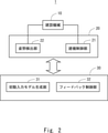
- FIG. 2 shows a schematic block diagram of the work control system according to the first embodiment.
- the construction machine 10 is shown as the one to be controlled by the work control system 1.
- the attitude control device 20 is provided with a construction machine control unit 21 and an attitude detection unit 22.
- the work control device 30 is provided with an initial input model generation unit 31 and a feedback control unit 32. Then, the construction machine 10 is operated by using the attitude control device 20 and the work control device 30.
- FIG. 1 shows a schematic block diagram of the work control system according to the first embodiment.
- the construction machine 10 is shown as the one to be controlled by the work control system 1.
- the attitude control device 20 is provided with a construction machine control unit 21 and an attitude detection unit 22.
- the work control device 30 is provided with an initial input model generation unit 31 and a feedback control unit 32. Then, the construction machine 10 is operated by using the attitude control device 20 and the work control device 30.
- FIG. 1 shows a schematic block diagram of the work control system according to the first embodiment.
- the attitude control device 20 and the work control device 30 can be used as one device, and the construction machine 10 and the attitude control device 20 can be connected by communication.
- the attitude control device 20 may be provided so as to be integrated with the construction machine 10, and the attitude control device 20 and the work control device 30 may be connected by communication.
- the work control device 30 can be arranged in the cloud storage and can be connected to the attitude control device 20 by communication.
- the construction machine 10 is a control target by the work control device 30, and the attitude control device 20 is also regarded as an interface for the work control device 30 to specifically operate the construction machine 10. In that case, the work control device 30 Can be considered as the main part of the work control system 1.
- the work control device 30 has an initial input model generation unit 31 and a feedback control unit 32.
- the initial input model generation unit 31 generates an initial input model that calculates an initial input value at which the movable parts of the construction machine 10 (for example, the swivel base 12, the boom 14, the arm 15, and the bucket 16) start to move.
- the feedback control unit 32 calculates the initial motion input value corresponding to the posture of the construction machine 10 by using the initial motion input model, and specifies the control input value having a value equal to or higher than the initial motion input value.
- the initial input model generation unit 31 performs the first initial input measurement process, the second initial input measurement process, and the model generation process.
- the first initial motion measurement value at which the movable portion starts to move is measured in the first state in which the movable portion is controlled to the first position in the movable range of the movable portion.
- an initial input model for deriving an initial input value for an arbitrary posture of the construction machine 10 by complementing between the first initial measurement value and the second initial measurement value is generated.
- FIG. 3 shows a block diagram of the work control system 1 according to the first embodiment.
- the construction machine 10 which is the control target of the work control system 1 is also shown for the sake of explanation.
- the work control system 1 according to the first embodiment includes an attitude control device 20 and a work control device 30.
- the attitude control device 20 is provided with a construction machine control unit 21 and an attitude detection unit 22.
- the work control device 30 is provided with an initial input model generation unit 31 and a feedback control unit 32.
- the construction machine control unit 21 displaces the operation lever in the construction machine 10 by operating the actuator based on the Fordback control input value calculated by the feedback control unit 32. Further, in the construction machine control unit 21, when the initial input model generation unit 31 generates the initial input model, the control input value is given from the initial input model generation unit 31, and the construction machine 10 is based on the control input value. The operating lever shall be displaced.
- the posture detection unit 22 acquires the joint angles of each movable part from sensors 181 to 184 provided on the movable parts such as the arm of the construction machine 10 and outputs them as posture detection values indicating the posture of the construction machine 10.
- the initial input model generation unit 31 generates an initial input model that calculates an initial input value at which the movable portion of the construction machine 10 starts to move. Further, the feedback control unit 32 calculates the initial motion input value corresponding to the current posture using the initial motion input model, and calculates the feedback control input value that guarantees the initial motion input value as the minimum value.
- the initial input model generation unit 31 has an initial input measurement unit 311 and a model generation unit 312.
- the initial motion input measurement unit 311 outputs an input value given to the construction machine control unit 21 in order to displace the movable portion of the construction machine 10 when generating the initial motion input model, and the attitude detection value output by the attitude detection unit 22.
- the initial input value for each posture is measured. More specifically, the initial input measurement unit 311 carries out the first initial input value measurement step and the second initial input value measurement step.
- the first initial motion measurement value at which the movable portion starts to move is measured in the first state in which the movable portion is controlled to the first position in the movable range of the movable portion.
- the first initial input value measurement step an input value that changes stepwise in the first state in which the cylinder driving the movable part is extended is applied to the construction machine control unit 21, and the movable part starts to move.
- the input value is measured as the first initial measurement value.
- input is made so that the cylinder moves in the positive direction in which the cylinder expands and in the negative direction in which the cylinder contracts with respect to the cylinder in the first state. A value is given and the first initial measurement value is measured in each of the positive direction and the negative direction.
- the second initial input value measurement step an input value that changes stepwise in the second state in which the cylinder driving the movable part is shortened is applied to the construction machine control unit 21, and the movable part starts to move.
- the input value is measured as the second initial measurement value.
- the second initial input value measurement step input is made so that the cylinder moves in the positive direction in which the cylinder expands and in the negative direction in which the cylinder contracts with respect to the cylinder in the second state. A value is given and the second initial measurement value is measured in each of the positive direction and the negative direction.
- the model generation unit 312 implements a model generation step of generating an initial motion input model that complements between the first initial motion measurement value and the second initial motion measurement value and derives the initial motion input value for an arbitrary posture of the construction machine 10. do.
- the feedback control unit 32 has an initial input update unit 321, an error update unit 322, and a control input calculation unit 323.
- the initial motion input update unit 321 acquires the posture of the construction machine 10 based on the position information (for example, the posture detection value) of the movable part of the construction machine 10, and calculates the initial motion input value corresponding to the posture using the initial motion input model. Perform the initial input update step to update with the value.
- the error update unit 322 implements an error update step for updating the error between the current posture and the target posture of the construction machine 10.
- the control input calculation unit 323 performs a control input calculation step of calculating a feedback control input value for reducing the error and giving it to the construction machine 10 by using the error and the initial input value as inputs.
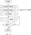
- FIG. 4 shows a flowchart illustrating the operation of the work control system according to the first embodiment.
- the work control system 1 according to the first embodiment performs an initial input model generation process before starting operation (step S1).
- step S1 the construction machine control unit 21, the attitude detection unit 22, and the initial input model generation unit 31 are used to generate an initial input model.
- step S1 the initial input model generation process of step S1
- the first initial input measurement process, the second initial input measurement process, and the model generation process are performed.
- the feedback control process for operating the construction machine 10 using the initial input model generated in step S1 is continued until the end of the operation (steps S2 and S3). That is, in the work control system 1 according to the first embodiment, the initial input model is generated in a period other than the operating period in which the construction machine 10 performs the work. By generating the initial input model during a period other than the operating period of the construction machine 10 in this way, the initial input model does not change while the construction machine 10 is in operation, and the construction machine 10 can be stably operated.
- FIG. 5 is shown in a flowchart illustrating the operation of the initial input model generation unit according to the first embodiment.
- the initial input model generation unit 31 selects a drive portion for which the initial input measurement unit 311 has not measured the initial input value (step S11).
- the initial input measurement unit 311 performs the processes of steps S12 and S13 as the first initial input measurement step.
- the initial motion input measurement unit 311 measures the initial motion input value in the negative direction of the first initial motion input value measurement step for the selected drive portion (step S12). More specifically, in step S12, the initial motion input measuring unit 311 measures the initial motion input value in the negative direction in the maximum posture (for example, the first state) detected by the posture detecting unit.
- the initial input value measured in step S12 is shown by Eq. (1).
- ⁇ upper is the posture angle detected by the construction machine control unit 21 from the drive portion when the first state is reached.
- the initial motion input measurement unit 311 measures the initial motion input value in the positive direction of the first initial motion input value measurement step for the selected drive portion (step S13). More specifically, in step S13, the initial motion input measuring unit 311 measures the initial motion input value in the positive direction in the maximum posture (for example, the first state) detected by the posture detecting unit.
- the initial input value measured in step S13 is shown by Eq. (2).
- the initial input measurement unit 311 performs the processes of steps S14 and S15 as the second initial input measurement step.
- the initial motion input measurement unit 311 measures the initial motion input value in the negative direction of the second initial motion input value measurement step for the selected drive portion (step S14). More specifically, in step S14, the initial motion input measuring unit 311 measures the initial motion input value in the negative direction in the minimum posture (for example, the second state) detected by the posture detecting unit.
- the initial input value measured in step S14 is shown by Eq. (3).
- ⁇ lower is the posture angle detected by the construction machine control unit 21 from the drive portion when the second state is reached.
- the initial motion input measurement unit 311 measures the initial motion input value in the positive direction of the second initial motion input value measurement step for the selected drive portion (step S15). More specifically, in step S15, the initial motion input measuring unit 311 measures the initial motion input value in the positive direction in the minimum posture (for example, the second state) detected by the posture detecting unit.
- the initial input value measured in step S15 is shown by Eq. (4).
- the initial input model generation unit 31 calculates the initial input model by the model generation unit 312 using the four initial input values acquired by the initial input measurement unit 311 (step S16).
- There are two initial input models generated in step S16 for example, a positive direction in which the cylinder extends and a negative direction in which the cylinder contracts. Therefore, the initial input models generated by the initial input model generation unit 31 according to the first embodiment are shown in the equations (5) and (7).
- Equation (5) shows the initial input model Umin_p ( ⁇ ) when the cylinder is displaced in the positive direction
- equation (7) shows the initial input model Umin_m ( ⁇ ) when the cylinder is displaced in the negative direction. show.
- ⁇ indicates the posture angle of the drive portion detected by the posture detection unit 22. It should be noted that ⁇ + in Eq. (5) is expressed by Eq. (6). It should be noted that ⁇ ⁇ in Eq. (7) is expressed by Eq. (8).
- the initial input model generation unit 31 repeats the processes of steps S11 to S16 for all the drive parts of the construction machine 10. Then, the initial input model generation unit 31 ends the initial input model generation process in response to the generation of the initial input model for all the drive parts of the construction machine 10.
- the model generation unit 312 of the initial input model generation unit 31 updates the initial input model held in the initial input update unit 321 by the generated initial input model.
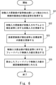
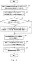
- FIG. 6 shows a flowchart illustrating the operation of the feedback control unit 32 according to the first embodiment.
- the feedback control unit 32 first obtains the posture detection value of the controlled target portion of the construction machine 10 from the posture detection unit 22 by using the initial input update unit 321 and then obtains the posture detection value of the control target portion of the construction machine 10 and the current posture ⁇ of the construction machine 10. (Step S21).
- the initial motion input update unit 321 updates the initial motion input value associated with the current posture ⁇ using the held initial motion input model (step S22).
- the error updating unit 322 updates the error between the current posture ⁇ and the target posture (step S23).
- the control input calculation unit 323 calculates the feedback control input value for the current posture ⁇ (step S24), and gives the calculated feedback control input value to the construction machine control unit 21 (step S25).
- the feedback control unit 32 controls until the posture of the construction machine 10 reaches the target posture while repeating the processes of steps S23 to S25.
- the feedback control input value u is expressed by the equation (9).
- ⁇ is the current posture
- ⁇ r is the target posture
- Umax is the maximum input value
- Umin ( ⁇ ) is the initial input value (however, the posture direction is omitted)
- Emax is the error between the target posture and the current posture.
- Kp is expressed by the equation (10).
- e is expressed by the equation (11).
- the feedback control input value is a value whose minimum value is the initial input value Umin ( ⁇ ). That is, it can be seen that the control input calculation unit 323 calculates the feedback control input value compensated with the initial input value calculated for each posture of the construction machine 10 at the start of control as the minimum value.
- the drive parts of the construction machine 10 are set to the first state and the second state having different displacement amounts, and the first state and the second state are set. Measure the initial input value for each. Then, the work control system 1 generates an initial motion input model capable of calculating an appropriate initial motion input value for an arbitrary posture using the measured initial motion input value. The work control system 1 calculates the optimum initial input value for the current posture using the initial input model generated by the initial input model generation unit 31, and inputs the feedback control input value that compensates for this initial input value as the minimum value. The model generation unit 31 calculates.
- the work control system 1 has a feedback control input value capable of controlling the construction machine 10 with high accuracy even if the play amount of the operation lever differs depending on the posture of the construction machine 10.
- the construction machine 10 can be controlled.
- Embodiment 2 In the second embodiment, the work control system 2 which is another form of the work control system 1 according to the first embodiment will be described. In the description of the second embodiment, the same components as those of the first embodiment are designated by the same reference numerals as those of the first embodiment, and the description thereof will be omitted.
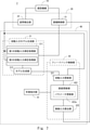
- FIG. 7 shows a block diagram of the work control system 2 according to the second embodiment.
- the work control system 2 according to the second embodiment is obtained by adding a work instruction unit 41 to the work control system 1 according to the first embodiment.
- the work control system 2 according to the second embodiment replaces the feedback control unit 32 of the work control system 1 according to the first embodiment with a feedback control unit 42.
- the feedback control unit 42 replaces the error update unit 322 with the error update unit 422.
- the error update unit 422 is obtained by adding the parameter update unit 422a to the error update unit 322.
- the work instruction unit 41 gives information on the content of the work performed by using the construction machine 10 to the feedback control unit 42.
- the error updating unit 422 of the feedback control unit 42 recognizes that the work instruction for instructing the construction machine 10 to perform the work is updated based on the instruction given from the work instruction unit 41, the parameter updating unit 422a
- the parameter update step of updating the control parameter including the target posture of the construction machine 10 is performed. It is assumed that the control parameters include the maximum input amount Umax and the deceleration start threshold value Emax included in the equation (10).
- FIG. 8 shows a flowchart illustrating the operation of the feedback control unit 42 according to the second embodiment.
- steps S31 and S32 different from the flowchart of the work control system 1 according to the first embodiment shown in FIG. 6 will be described.
- step S31 it is determined whether or not the work instruction unit 41 has updated the work content. Then, when it is determined in step S31 that the work content has been updated, the error update unit 422 uses the parameter update unit 422a to control parameters including the target posture, the maximum input amount, and the deceleration start threshold value according to the current work content. To update.
- the error from the current posture is calculated (step S24) and the feedback control input value is calculated based on the target posture, the input maximum amount, and the deceleration start threshold value updated in step S32. (Step SS25) is performed.
- the work instruction unit 41 instructs the error update unit 422 to update the work content, whereby the construction machine 10 is made to perform various operations.
- the work control system 1 it is possible to perform the same high-precision control as the work control system 1 according to the first embodiment.
- a force for closing the bucket 16 for the bucket 16 to lift the earth and sand is required more than when the bucket 16 is empty. Therefore, in the excavation work, a control parameter that increases the torque applied to the bucket 16 is adopted.
- control parameters that improve position accuracy are adopted in the work of loading earth and sand on trucks.
- the present invention has been described as a hardware configuration, but the present invention is not limited thereto.
- the present invention can also realize arbitrary processing (for example, the processing described with reference to FIGS. 4 to 6 and 8) by causing a CPU (Central Processing Unit) to execute a computer program.
- the above-mentioned program can be stored and supplied to a computer by using various types of non-transitory computer-readable media (non-transitory computer readable medium).
- Non-temporary computer-readable media include various types of tangible storage media.
- non-temporary computer-readable media examples include magnetic recording media (eg, flexible disks, magnetic tapes, hard disk drives), magneto-optical recording media (eg, magneto-optical disks), CD-ROMs (Read Only Memory), CD-Rs, etc. Includes CD-R / W, semiconductor memory (for example, mask ROM, PROM (Programmable ROM), EPROM (Erasable PROM), flash ROM, RAM (Random Access Memory)).
- the program may also be supplied to the computer by various types of temporary computer-readable media. Examples of temporary computer readable media include electrical, optical, and electromagnetic waves.
- the temporary computer-readable medium can supply the program to the computer via a wired communication path such as an electric wire and an optical fiber, or a wireless communication path.
- the initial input model generation step to generate the initial input model that calculates the initial input value that starts to move the movable part of the construction machine, and Using the initial motion input model, the feedback control step of calculating the initial motion input value corresponding to the posture of the construction machine and specifying a control input value having a value equal to or higher than the initial motion input value is provided.
- the initial input model generation step is A first initial input value measurement step for measuring a first initial measurement value at which the movable portion starts to move in a first state in which the movable portion is controlled to a first position in the movable range of the movable portion.
- Work control method with. (Appendix 2) In the first initial input value measurement step, the construction machine is moved so as to move in the positive direction of the movable portion and in the negative direction of the movable portion with respect to the movable portion in the first state. Given the input value, measure the first initial measurement value in each of the positive direction and the negative direction.
- the construction machine is moved so as to move in the positive direction of the movable portion and in the negative direction of the movable portion with respect to the movable portion in the second state. Given the input value, measure the second initial measurement value in each of the positive and negative directions.
- the model generation step the first initial motion measurement value in the positive direction, the first initial motion measurement value in the negative direction, the second initial motion measurement value in the positive direction, and the second initial motion in the negative direction.
- the work control method according to Appendix 1 further comprising a control input calculation step for generating the initial input model using the measured values.
- the feedback control step is Initial motion input update that acquires the current posture of the construction machine based on the position information of the movable part of the construction machine and updates the initial motion input value corresponding to the current posture with a value calculated using the initial motion input model.
- Steps and An error update step for updating the error between the current posture and the target posture of the construction machine and The work control method according to Supplementary Note 1 or 2, further comprising a control input calculation step of calculating the control input value for reducing the error by using the error and the initial input value as inputs and giving the control input value to the construction machine.
- the work control method according to any one of Supplementary note 1 to 5, further comprising a construction machine control step for controlling the construction machine via the operation lever by operating the actuator based on the control input value.
- An initial input model generation means for generating an initial input model for calculating an initial input value at which a movable part of a construction machine starts to move, Using the initial motion input model, the feedback control means for calculating the initial motion input value corresponding to the posture of the construction machine and specifying a control input value having a value equal to or higher than the initial motion input value is provided.
- the initial input model generation means The first initial input value measurement process for measuring the first initial measurement value at which the movable portion starts to move in the first state in which the movable portion is controlled to the first position in the movable range of the movable portion. A second measurement of a second initial motion measurement value at which the movable portion starts to move in a second state in which the movable portion is controlled to a second position different from the first position in the movable range of the movable portion.
- Initial input value measurement processing and A model generation process for generating the initial input model for deriving the initial input value for an arbitrary posture of the construction machine by complementing between the first initial measurement value and the second initial measurement value. Work control system to do.
- the construction machine In the first initial input value measurement process, the construction machine is moved so as to move in the positive direction of the movable portion and in the negative direction of the movable portion with respect to the movable portion in the first state. Given the input value, measure the first initial measurement value in each of the positive and negative directions, In the first initial input value measurement process, the construction machine is moved so as to move in the positive direction of the movable portion and in the negative direction of the movable portion with respect to the movable portion in the second state. Given the input value, measure the second initial measurement value in each of the positive and negative directions.
- the work control system according to Appendix 7, which generates the initial input model using the measured values.
- the feedback control means is Initial motion input update that acquires the current posture of the construction machine based on the position information of the movable part of the construction machine and updates the initial motion input value corresponding to the current posture with a value calculated using the initial motion input model.
- the work control system according to Supplementary note 7 or 8, further comprising a control input calculation means for calculating a control input value for reducing the error by using the error and the initial input value as inputs and giving the control input value to the construction machine.
- An initial input model generation means for generating an initial input model for calculating an initial input value at which a movable part of a construction machine starts to move, Using the initial motion input model, the feedback control means for calculating the initial motion input value corresponding to the posture of the construction machine and specifying a control input value having a value equal to or higher than the initial motion input value is provided.
- the initial input model generation means The first initial input value measurement process for measuring the first initial measurement value at which the movable portion starts to move in the first state in which the movable portion is controlled to the first position in the movable range of the movable portion.
- Work control device to do. In the first initial input value measurement process, the construction machine is moved so as to move in the positive direction of the movable portion and in the negative direction of the movable portion with respect to the movable portion in the first state.
- the construction machine is moved so as to move in the positive direction of the movable portion and in the negative direction of the movable portion with respect to the movable portion in the second state.
- the input value measure the second initial measurement value in each of the positive and negative directions.
- the model generation process the first initial motion measurement value in the positive direction, the first initial motion measurement value in the negative direction, the second initial motion measurement value in the positive direction, and the second initial motion in the negative direction.
- the work control device according to Appendix 13, which generates the initial input model using the measured values.
- the feedback control means is Initial motion input update that acquires the current posture of the construction machine based on the position information of the movable part of the construction machine and updates the initial motion input value corresponding to the current posture with a value calculated using the initial motion input model.
- Means and An error updating means for updating the error between the current posture and the target posture of the construction machine.
- the work control device according to Appendix 13 or 14, further comprising a control input calculation means for calculating the control input value for reducing the error by using the error and the initial input value as inputs and giving the control input value to the construction machine.
Landscapes
- Engineering & Computer Science (AREA)
- Mining & Mineral Resources (AREA)
- Civil Engineering (AREA)
- General Engineering & Computer Science (AREA)
- Structural Engineering (AREA)
- Operation Control Of Excavators (AREA)
Priority Applications (2)
| Application Number | Priority Date | Filing Date | Title |
|---|---|---|---|
| US18/022,813 US20240044108A1 (en) | 2020-08-28 | 2021-07-15 | Work control method of construction machine, work control system, and work control apparatus |
| JP2022545527A JP7472991B2 (ja) | 2020-08-28 | 2021-07-15 | 建設機械の作業制御方法、作業制御システム及び作業制御装置 |
Applications Claiming Priority (2)
| Application Number | Priority Date | Filing Date | Title |
|---|---|---|---|
| JP2020-144049 | 2020-08-28 | ||
| JP2020144049 | 2020-08-28 |
Publications (1)
| Publication Number | Publication Date |
|---|---|
| WO2022044601A1 true WO2022044601A1 (ja) | 2022-03-03 |
Family
ID=80354982
Family Applications (1)
| Application Number | Title | Priority Date | Filing Date |
|---|---|---|---|
| PCT/JP2021/026600 Ceased WO2022044601A1 (ja) | 2020-08-28 | 2021-07-15 | 建設機械の作業制御方法、作業制御システム及び作業制御装置 |
Country Status (3)
| Country | Link |
|---|---|
| US (1) | US20240044108A1 (cg-RX-API-DMAC7.html) |
| JP (1) | JP7472991B2 (cg-RX-API-DMAC7.html) |
| WO (1) | WO2022044601A1 (cg-RX-API-DMAC7.html) |
Citations (4)
| Publication number | Priority date | Publication date | Assignee | Title |
|---|---|---|---|---|
| JPH0610906A (ja) * | 1992-01-07 | 1994-01-21 | Caterpillar Inc | 流体圧制御装置 |
| JPH09328785A (ja) * | 1996-04-10 | 1997-12-22 | Komatsu Ltd | 建設機械の作業機制御装置 |
| JP2002234700A (ja) * | 2001-11-26 | 2002-08-23 | Komatsu Ltd | マニピュレータの姿勢角度制御装置 |
| JP2017057644A (ja) * | 2015-09-17 | 2017-03-23 | 住友重機械工業株式会社 | ショベル |
Family Cites Families (15)
| Publication number | Priority date | Publication date | Assignee | Title |
|---|---|---|---|---|
| JPH0735105A (ja) * | 1993-07-21 | 1995-02-03 | Komatsu Ltd | 油圧駆動機械の不感帯自動補正装置およびその不感帯自動補正方法 |
| DE19839062C2 (de) * | 1997-08-29 | 2002-04-18 | Komatsu Mfg Co Ltd | Hydraulische Maschinensteuerung |
| US6850806B2 (en) * | 1999-04-16 | 2005-02-01 | Siemens Energy & Automation, Inc. | Method and apparatus for determining calibration options in a motion control system |
| JP3940242B2 (ja) * | 1999-07-29 | 2007-07-04 | 日立建機株式会社 | 建設機械の油圧回路制御装置 |
| JP4248725B2 (ja) * | 2000-03-21 | 2009-04-02 | 国土交通省北陸地方整備局長 | 複数種類の自律走行作業機を遠隔操作する遠隔操作装置 |
| US8132345B2 (en) * | 2007-06-15 | 2012-03-13 | Deere & Company | Hydraulic function control with auto-control mode override |
| WO2008156442A1 (en) * | 2007-06-15 | 2008-12-24 | Deere & Company | Hydraulic function auto-control mode deactivation |
| JP6023053B2 (ja) * | 2011-06-10 | 2016-11-09 | 日立建機株式会社 | 作業機械 |
| JP6495729B2 (ja) * | 2015-04-28 | 2019-04-03 | 日立建機株式会社 | 建設機械の制御装置 |
| JP6552996B2 (ja) * | 2016-06-07 | 2019-07-31 | 日立建機株式会社 | 作業機械 |
| JP7078120B2 (ja) * | 2018-09-05 | 2022-05-31 | 日本電気株式会社 | モーション制御装置、モーション制御方法、モーション制御プログラム、及びモーション制御システム |
| JP7283070B2 (ja) * | 2018-12-19 | 2023-05-30 | コベルコ建機株式会社 | 作業機械用周辺監視装置 |
| JP6998493B2 (ja) * | 2019-03-06 | 2022-01-18 | 日立建機株式会社 | 建設機械 |
| US20200392696A1 (en) * | 2019-06-11 | 2020-12-17 | Caterpillar Inc. | Method for operating an implement of a work machine |
| JP7305274B2 (ja) * | 2019-09-25 | 2023-07-10 | 日立建機株式会社 | 建設機械 |
-
2021
- 2021-07-15 JP JP2022545527A patent/JP7472991B2/ja active Active
- 2021-07-15 US US18/022,813 patent/US20240044108A1/en active Pending
- 2021-07-15 WO PCT/JP2021/026600 patent/WO2022044601A1/ja not_active Ceased
Patent Citations (4)
| Publication number | Priority date | Publication date | Assignee | Title |
|---|---|---|---|---|
| JPH0610906A (ja) * | 1992-01-07 | 1994-01-21 | Caterpillar Inc | 流体圧制御装置 |
| JPH09328785A (ja) * | 1996-04-10 | 1997-12-22 | Komatsu Ltd | 建設機械の作業機制御装置 |
| JP2002234700A (ja) * | 2001-11-26 | 2002-08-23 | Komatsu Ltd | マニピュレータの姿勢角度制御装置 |
| JP2017057644A (ja) * | 2015-09-17 | 2017-03-23 | 住友重機械工業株式会社 | ショベル |
Also Published As
| Publication number | Publication date |
|---|---|
| JPWO2022044601A1 (cg-RX-API-DMAC7.html) | 2022-03-03 |
| US20240044108A1 (en) | 2024-02-08 |
| JP7472991B2 (ja) | 2024-04-23 |
Similar Documents
| Publication | Publication Date | Title |
|---|---|---|
| US9752298B2 (en) | Trace generation device and working machine | |
| JP6526321B2 (ja) | 作業機械 | |
| US10017912B2 (en) | Work vehicle with improved loader/implement position control and return-to-position functionality | |
| JP4647325B2 (ja) | 建設機械の作業機の制御装置、建設機械の作業機の制御方法、及びこの方法をコンピュータに実行させるプログラム | |
| US20210215483A1 (en) | Controlling movement of a machine using sensor fusion | |
| US20130103247A1 (en) | Apparatus and Method for Controlling Work Trajectory of Construction Equipment | |
| JP7078120B2 (ja) | モーション制御装置、モーション制御方法、モーション制御プログラム、及びモーション制御システム | |
| CN112639212B (zh) | 作业机械 | |
| JP2024156796A (ja) | 作業制御方法、作業制御システム及び目標点設定装置 | |
| CN111032962B (zh) | 工程机械 | |
| CN112585321A (zh) | 工程机械 | |
| US20210332555A1 (en) | Hystat swing motion actuation, monitoring, and control system | |
| KR101485003B1 (ko) | 로봇의 위치 및 자세 제어 장치 및 방법 | |
| JPWO2019176075A1 (ja) | 作業機械 | |
| JP7405275B2 (ja) | 建設機械の作業制御方法、作業制御システム及び作業制御装置 | |
| CN115182407A (zh) | 用于控制臂架的方法、装置、控制器及工程机械 | |
| JP7472991B2 (ja) | 建設機械の作業制御方法、作業制御システム及び作業制御装置 | |
| US20210148081A1 (en) | Work machine | |
| JP2014174842A (ja) | S字加減速制御プログラム、動作制御プログラム、記録媒体、コントローラ、s字加減速制御演算方法およびワーク動作制御システム | |
| CN118832590A (zh) | 机械臂控制方法、装置、设备及存储介质 | |
| KR20250022869A (ko) | 작업 기계 | |
| WO2024043303A1 (ja) | 制御装置及び制御方法 | |
| JP7355254B2 (ja) | 作業制御方法、作業制御システム及び作業制御装置 | |
| JPWO2022044601A5 (cg-RX-API-DMAC7.html) | ||
| CN116335221B (zh) | 用于控制工程机械进行作业的方法和装置及工程机械 |
Legal Events
| Date | Code | Title | Description |
|---|---|---|---|
| 121 | Ep: the epo has been informed by wipo that ep was designated in this application |
Ref document number: 21861030 Country of ref document: EP Kind code of ref document: A1 |
|
| ENP | Entry into the national phase |
Ref document number: 2022545527 Country of ref document: JP Kind code of ref document: A |
|
| WWE | Wipo information: entry into national phase |
Ref document number: 18022813 Country of ref document: US |
|
| NENP | Non-entry into the national phase |
Ref country code: DE |
|
| 122 | Ep: pct application non-entry in european phase |
Ref document number: 21861030 Country of ref document: EP Kind code of ref document: A1 |