WO2022044535A1 - シート搬送装置、画像形成装置 - Google Patents
シート搬送装置、画像形成装置 Download PDFInfo
- Publication number
- WO2022044535A1 WO2022044535A1 PCT/JP2021/024746 JP2021024746W WO2022044535A1 WO 2022044535 A1 WO2022044535 A1 WO 2022044535A1 JP 2021024746 W JP2021024746 W JP 2021024746W WO 2022044535 A1 WO2022044535 A1 WO 2022044535A1
- Authority
- WO
- WIPO (PCT)
- Prior art keywords
- sheet
- discharge
- transport
- unit
- pair
- Prior art date
- Legal status (The legal status is an assumption and is not a legal conclusion. Google has not performed a legal analysis and makes no representation as to the accuracy of the status listed.)
- Ceased
Links
Images

Classifications
-
- B—PERFORMING OPERATIONS; TRANSPORTING
- B65—CONVEYING; PACKING; STORING; HANDLING THIN OR FILAMENTARY MATERIAL
- B65H—HANDLING THIN OR FILAMENTARY MATERIAL, e.g. SHEETS, WEBS, CABLES
- B65H31/00—Pile receivers
- B65H31/34—Apparatus for squaring-up piled articles
- B65H31/38—Apparatus for vibrating or knocking the pile during piling
-
- B—PERFORMING OPERATIONS; TRANSPORTING
- B65—CONVEYING; PACKING; STORING; HANDLING THIN OR FILAMENTARY MATERIAL
- B65H—HANDLING THIN OR FILAMENTARY MATERIAL, e.g. SHEETS, WEBS, CABLES
- B65H43/00—Use of control, checking, or safety devices, e.g. automatic devices comprising an element for sensing a variable
- B65H43/04—Use of control, checking, or safety devices, e.g. automatic devices comprising an element for sensing a variable detecting, or responding to, presence of faulty articles
-
- B—PERFORMING OPERATIONS; TRANSPORTING
- B65—CONVEYING; PACKING; STORING; HANDLING THIN OR FILAMENTARY MATERIAL
- B65H—HANDLING THIN OR FILAMENTARY MATERIAL, e.g. SHEETS, WEBS, CABLES
- B65H29/00—Delivering or advancing articles from machines; Advancing articles to or into piles
- B65H29/12—Delivering or advancing articles from machines; Advancing articles to or into piles by means of the nip between two, or between two sets of, moving tapes or bands or rollers
- B65H29/125—Delivering or advancing articles from machines; Advancing articles to or into piles by means of the nip between two, or between two sets of, moving tapes or bands or rollers between two sets of rollers
-
- B—PERFORMING OPERATIONS; TRANSPORTING
- B65—CONVEYING; PACKING; STORING; HANDLING THIN OR FILAMENTARY MATERIAL
- B65H—HANDLING THIN OR FILAMENTARY MATERIAL, e.g. SHEETS, WEBS, CABLES
- B65H31/00—Pile receivers
- B65H31/20—Pile receivers adjustable for different article sizes
-
- B—PERFORMING OPERATIONS; TRANSPORTING
- B65—CONVEYING; PACKING; STORING; HANDLING THIN OR FILAMENTARY MATERIAL
- B65H—HANDLING THIN OR FILAMENTARY MATERIAL, e.g. SHEETS, WEBS, CABLES
- B65H31/00—Pile receivers
- B65H31/34—Apparatus for squaring-up piled articles
-
- B—PERFORMING OPERATIONS; TRANSPORTING
- B65—CONVEYING; PACKING; STORING; HANDLING THIN OR FILAMENTARY MATERIAL
- B65H—HANDLING THIN OR FILAMENTARY MATERIAL, e.g. SHEETS, WEBS, CABLES
- B65H7/00—Controlling article feeding, separating, pile-advancing, or associated apparatus, to take account of incorrect feeding, absence of articles, or presence of faulty articles
- B65H7/02—Controlling article feeding, separating, pile-advancing, or associated apparatus, to take account of incorrect feeding, absence of articles, or presence of faulty articles by feelers or detectors
- B65H7/06—Controlling article feeding, separating, pile-advancing, or associated apparatus, to take account of incorrect feeding, absence of articles, or presence of faulty articles by feelers or detectors responsive to presence of faulty articles or incorrect separation or feed
- B65H7/10—Controlling article feeding, separating, pile-advancing, or associated apparatus, to take account of incorrect feeding, absence of articles, or presence of faulty articles by feelers or detectors responsive to presence of faulty articles or incorrect separation or feed responsive to incorrect side register
-
- B—PERFORMING OPERATIONS; TRANSPORTING
- B65—CONVEYING; PACKING; STORING; HANDLING THIN OR FILAMENTARY MATERIAL
- B65H—HANDLING THIN OR FILAMENTARY MATERIAL, e.g. SHEETS, WEBS, CABLES
- B65H9/00—Registering, e.g. orientating, articles; Devices therefor
- B65H9/004—Deskewing sheet by abutting against a stop, i.e. producing a buckling of the sheet
- B65H9/006—Deskewing sheet by abutting against a stop, i.e. producing a buckling of the sheet the stop being formed by forwarding means in stand-by
-
- B—PERFORMING OPERATIONS; TRANSPORTING
- B65—CONVEYING; PACKING; STORING; HANDLING THIN OR FILAMENTARY MATERIAL
- B65H—HANDLING THIN OR FILAMENTARY MATERIAL, e.g. SHEETS, WEBS, CABLES
- B65H9/00—Registering, e.g. orientating, articles; Devices therefor
- B65H9/10—Pusher and like movable registers; Pusher or gripper devices which move articles into registered position
- B65H9/103—Pusher and like movable registers; Pusher or gripper devices which move articles into registered position acting by friction or suction on the article for pushing or pulling it into registered position, e.g. against a stop
-
- B—PERFORMING OPERATIONS; TRANSPORTING
- B65—CONVEYING; PACKING; STORING; HANDLING THIN OR FILAMENTARY MATERIAL
- B65H—HANDLING THIN OR FILAMENTARY MATERIAL, e.g. SHEETS, WEBS, CABLES
- B65H9/00—Registering, e.g. orientating, articles; Devices therefor
- B65H9/16—Inclined tape, roller, or like article-forwarding side registers
- B65H9/166—Roller
-
- B—PERFORMING OPERATIONS; TRANSPORTING
- B65—CONVEYING; PACKING; STORING; HANDLING THIN OR FILAMENTARY MATERIAL
- B65H—HANDLING THIN OR FILAMENTARY MATERIAL, e.g. SHEETS, WEBS, CABLES
- B65H2301/00—Handling processes for sheets or webs
- B65H2301/30—Orientation, displacement, position of the handled material
- B65H2301/33—Modifying, selecting, changing orientation
- B65H2301/331—Skewing, correcting skew, i.e. changing slightly orientation of material
-
- B—PERFORMING OPERATIONS; TRANSPORTING
- B65—CONVEYING; PACKING; STORING; HANDLING THIN OR FILAMENTARY MATERIAL
- B65H—HANDLING THIN OR FILAMENTARY MATERIAL, e.g. SHEETS, WEBS, CABLES
- B65H2404/00—Parts for transporting or guiding the handled material
- B65H2404/10—Rollers
- B65H2404/14—Roller pairs
- B65H2404/142—Roller pairs arranged on movable frame
- B65H2404/1422—Roller pairs arranged on movable frame reciprocating
-
- B—PERFORMING OPERATIONS; TRANSPORTING
- B65—CONVEYING; PACKING; STORING; HANDLING THIN OR FILAMENTARY MATERIAL
- B65H—HANDLING THIN OR FILAMENTARY MATERIAL, e.g. SHEETS, WEBS, CABLES
- B65H2404/00—Parts for transporting or guiding the handled material
- B65H2404/10—Rollers
- B65H2404/14—Roller pairs
- B65H2404/142—Roller pairs arranged on movable frame
- B65H2404/1424—Roller pairs arranged on movable frame moving in parallel to their axis
-
- B—PERFORMING OPERATIONS; TRANSPORTING
- B65—CONVEYING; PACKING; STORING; HANDLING THIN OR FILAMENTARY MATERIAL
- B65H—HANDLING THIN OR FILAMENTARY MATERIAL, e.g. SHEETS, WEBS, CABLES
- B65H2511/00—Dimensions; Position; Numbers; Identification; Occurrences
- B65H2511/10—Size; Dimensions
- B65H2511/12—Width
-
- B—PERFORMING OPERATIONS; TRANSPORTING
- B65—CONVEYING; PACKING; STORING; HANDLING THIN OR FILAMENTARY MATERIAL
- B65H—HANDLING THIN OR FILAMENTARY MATERIAL, e.g. SHEETS, WEBS, CABLES
- B65H2511/00—Dimensions; Position; Numbers; Identification; Occurrences
- B65H2511/20—Location in space
- B65H2511/24—Irregularities, e.g. in orientation or skewness
-
- B—PERFORMING OPERATIONS; TRANSPORTING
- B65—CONVEYING; PACKING; STORING; HANDLING THIN OR FILAMENTARY MATERIAL
- B65H—HANDLING THIN OR FILAMENTARY MATERIAL, e.g. SHEETS, WEBS, CABLES
- B65H2515/00—Physical entities not provided for in groups B65H2511/00 or B65H2513/00
- B65H2515/30—Forces; Stresses
- B65H2515/34—Pressure, e.g. fluid pressure
-
- B—PERFORMING OPERATIONS; TRANSPORTING
- B65—CONVEYING; PACKING; STORING; HANDLING THIN OR FILAMENTARY MATERIAL
- B65H—HANDLING THIN OR FILAMENTARY MATERIAL, e.g. SHEETS, WEBS, CABLES
- B65H2601/00—Problem to be solved or advantage achieved
- B65H2601/20—Avoiding or preventing undesirable effects
- B65H2601/27—Other problems
- B65H2601/272—Skewing of handled material during handling
-
- B—PERFORMING OPERATIONS; TRANSPORTING
- B65—CONVEYING; PACKING; STORING; HANDLING THIN OR FILAMENTARY MATERIAL
- B65H—HANDLING THIN OR FILAMENTARY MATERIAL, e.g. SHEETS, WEBS, CABLES
- B65H2801/00—Application field
- B65H2801/03—Image reproduction devices
- B65H2801/06—Office-type machines, e.g. photocopiers
Definitions
- the present invention relates to a sheet transfer device provided with a mechanism for correcting a positional deviation in the width direction of a sheet, and an image forming device including the mechanism.
- the position of the sheet in the width direction may shift.
- the sheet transport device includes a sheet correction mechanism for correcting the position of the sheet in the width direction (see, for example, Patent Document 1).
- the position of the sheet in the width direction may shift again by the time the sheet is discharged to the discharge tray.
- An object of the present invention is to provide a sheet transport device capable of correcting a positional deviation in the width direction of the sheet that occurs in the process from the sheet correction mechanism to the discharge tray in the sheet transport path, and an image forming device including the same. It is in.
- the sheet transfer device includes a sheet transfer unit, a sheet discharge unit, a seat shift unit, a transfer position detection unit, a discharge position detection unit, and a control unit.
- the sheet transport section transports the sheet along the transport path.
- the sheet discharging section discharges the sheet from the discharging port to the discharging tray on the downstream side of the sheet transporting section.
- the sheet shift portion is arranged in the transport path and moves the sheet along a width direction orthogonal to the sheet transport direction.
- the transport position detection unit detects the position of the sheet in the width direction in the transport path.
- the discharge position detection unit detects the discharge position of the sheet discharged onto the discharge tray in the width direction in the sheet discharge unit.
- the control unit controls the transfer of the sheet.
- the control unit Based on the detection result of the discharge position detection unit, the control unit derives a deviation amount between the discharge position of the sheet and the emission standard position as a reference in the width direction in the sheet discharge unit, and responds to the deviation amount. By controlling the sheet shift section, the transfer position of the sheet in the sheet transfer section is corrected.
- the image forming apparatus includes a printing apparatus for forming an image on a sheet and the sheet conveying apparatus for conveying the sheet after image formation.
- a sheet transport device capable of correcting a positional deviation in the width direction of the sheet that occurs in the process from the sheet correction mechanism to the discharge tray in the sheet transport path, and an image forming device including the same. Will be possible.
- FIG. 1 is a diagram showing a configuration of an image forming apparatus including the sheet transporting apparatus according to the embodiment.
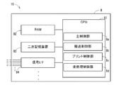
- FIG. 2 is a block diagram showing a configuration of a control device in the sheet transport device according to the embodiment.
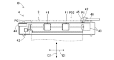
- FIG. 3 is a diagram showing a configuration of a sheet correction mechanism in the sheet transport device according to the embodiment.
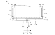
- FIG. 4 is a diagram showing a configuration of a discharge sheet matching mechanism in the sheet transfer device according to the embodiment.
- the sheet transport device 6 As shown in FIG. 1, the sheet transport device 6 according to the embodiment constitutes a part of the image forming device 10.
- the image forming apparatus 10 includes a printing apparatus 1, a relay transfer apparatus 2, and a post-processing apparatus 3.
- the sheet transfer device 6 is composed of a part of the printing device 1, a part of the relay transfer device 2, and a part of the post-processing device 3.
- the image forming apparatus 10 further includes a control device 8 for controlling a printing device 1, a relay transfer device 2, and a post-processing device 3.
- a primary transport path 1x is formed in the printing apparatus 1, a secondary transport path 2x is formed in the relay transport device 2, and a tertiary transport path 3x is formed in the post-processing device 3. ..
- the primary transport path 1x, the secondary transport path 2x, and the tertiary transport path 3x are passages through which the sheet 9 is transported, respectively.
- the printing device 1 includes a sheet accommodating unit 11, a primary transfer mechanism 12, and a printing unit 13.
- the primary transfer mechanism 12 sends out the sheets 9 accommodated in the sheet accommodating portion 11 one by one to the primary transfer path 1x, and further conveys the sheets 9 along the primary transfer path 1x.
- the print unit 13 executes a print process of forming an image on the sheet 9 transported along the primary transport path 1x.
- the print unit 13 shown in FIG. 1 executes the print process by an inkjet method.
- the printing unit 13 may be a device that executes the printing process by another method such as an electrophotographic method.
- the primary transfer mechanism 12 sends the sheet 9 after image formation from the primary transfer path 1x to the secondary transfer path 2x in the relay transfer device 2.
- the relay transfer device 2 transfers the image-formed sheet 9 carried in from the printing device 1 to the post-processing device 3.
- the relay transfer device 2 includes a secondary transfer mechanism 21 and one or more sheet correction mechanisms 4. In the example shown in FIG. 1, the relay transfer device 2 includes two sheet correction mechanisms 4.
- the secondary transfer mechanism 21 conveys the sheet 9 carried in from the printing device 1 along the secondary transfer path 2x, and further sends the sheet 9 to the post-processing device 3.
- the secondary transport mechanism 21 reverses the orientation of the sheet 9 carried in from the printing device 1 and the sequential transport process in which the sheet 9 is sent out to the post-processing device 3 while maintaining the orientation of the sheet 9 carried in from the printing device 1. It is possible to execute the reverse transfer process of sending the sheet 9 to the post-processing device 3 above.
- the secondary transfer mechanism 21 is an example of a sheet transfer unit.
- FIG. 1 an example of a transport path of the sheet 9 when the forward transport process is performed is shown by a broken line arrow, and an example of a transport path of the sheet 9 when the reverse transport process is performed is shown by a solid line arrow. Has been done.
- the relay transfer device 2 includes an intermediate discharge tray 20.
- the secondary transfer mechanism 21 can also execute an intermediate discharge process of discharging the sheet 9 carried in from the printing device 1 to the intermediate discharge tray 20.
- the transport path of the sheet 9 when the intermediate discharge process is performed is indicated by the arrow of the alternate long and short dash line.
- first direction D1 the horizontal direction orthogonal to the transport direction of the sheet 9 in each of the primary transport path 1x, the secondary transport path 2x, and the tertiary transport path 3x is referred to as a first direction D1 and is orthogonal to the first direction D1.
- the horizontal direction is referred to as the second direction D2.
- the first direction D1 is the width direction of the sheet 9 transported along each of the primary transport path 1x, the secondary transport path 2x, and the tertiary transport path 3x.
- the front-back direction of the image forming apparatus 10 is the first direction D1.
- the left-right direction of the image forming apparatus 10 is the second direction D2.
- Each of the sheet correction mechanisms 4 is arranged in the middle of the secondary transport path 2x. Each of the sheet correction mechanisms 4 moves the sheet 9 along the first direction D1.
- the position of the sheet 9 in the first direction D1 may shift.
- Each of the seat correction mechanisms 4 corrects the misalignment of the seat 9 in the first direction D1.
- the secondary transport path 2x has a plurality of parallel transport paths 20x formed in parallel from the branch portion 2y to the confluence portion 2z.
- the secondary transport mechanism 21 includes a route switching mechanism 210 that selectively guides the sheet 9 that has reached the branch portion 2y to any one of the plurality of parallel transport paths 20x.
- the route switching mechanism 210 guides a plurality of sheets 9 sequentially transported to the branch portion 2y to each of the plurality of parallel transport paths 20x in a predetermined order.
- the printing process for a plurality of sheets 9 is continuously executed.
- the secondary transport path 2x has two parallel transport paths 20x as a passage of the sheet 9 when the reverse transport process is executed.
- the two sheet correction mechanisms 4 are arranged in two parallel transport paths 20x in the middle of the secondary transport path 2x, respectively.
- the route switching mechanism 210 alternately guides the sheet 9 that has reached the branch portion 2y to the two parallel transport paths 20x.
- the succeeding sheet 9 is conveyed to another sheet correction mechanism 4 without waiting for the completion of the processing of the sheet correction mechanism 4 for the preceding sheet 9.
- the aftertreatment device 3 includes a tertiary transfer mechanism 31, one or more sheet processing mechanisms 32, and one or more discharge trays 33.
- the tertiary transfer mechanism 31 conveys the sheet 9 carried in from the relay transfer device 2 along the tertiary transfer path 3x, and further discharges the sheet 9 that has passed through the sheet processing mechanism 32 from the discharge port 30 onto the discharge tray 33.
- the discharge port 30 is an outlet of the tertiary transport path 3x.
- the tertiary transfer mechanism 31 is an example of a sheet discharging unit arranged on the downstream side of the secondary transfer mechanism 21.
- the discharge port 30 is formed in the housing of the aftertreatment device 3 that includes the tertiary transport mechanism 31.
- the primary transfer mechanism 12, the secondary transfer mechanism 21, and the tertiary transfer mechanism 31 convey the sheet 9 along the primary transfer path 1x, the secondary transfer path 2x, and the tertiary transfer path 3x, and further transfer the sheet 9.
- the transport mechanisms 12, 21, and 31 for discharging from the tertiary transport path 3x to the discharge tray 33 are configured.
- the transfer mechanism 12, 21, 31, the sheet correction mechanism 4 and the discharge sheet matching mechanism 5 constitute a sheet transfer device 6.
- the sheet processing mechanism 32 includes a drilling mechanism 32a, a staple mechanism 32b, and a sheet folding mechanism 32c.
- the drilling mechanism 32a performs a drilling process on the sheet 9.
- the staple mechanism 32b stacks and aligns a plurality of sheets 9, and further staples the aligned plurality of sheets 9.
- the sheet folding mechanism 32c performs a folding process for making a crease on one sheet 9 or a plurality of stacked sheets 9.
- the aftertreatment device 3 further includes a discharge sheet matching mechanism 5.
- the discharge sheet matching mechanism 5 aligns the position of the first direction D1 of the discharged sheet 9 on the discharge tray 33 with a predetermined reference position.
- control device 8 includes a CPU (Central Processing Unit) 81 and peripheral devices such as a RAM (Random Access Memory) 82, a secondary storage device 83, and a signal interface 84.
- CPU Central Processing Unit
- peripheral devices such as a RAM (Random Access Memory) 82, a secondary storage device 83, and a signal interface 84.
- the CPU 81 is a processor that executes various data processing and control by executing a computer program.
- the RAM 82 is a computer-readable volatile storage device. The RAM 82 primarily stores the computer program executed by the CPU 81 and the data to be output and referenced in the process of executing various processes by the CPU 81.
- the secondary storage device 83 is a non-volatile storage device that can be read by a computer.
- the secondary storage device 83 can store and update the computer program and various data.
- one or both of the flash memory and the hard disk drive are adopted as the secondary storage device 83.
- the signal interface 84 converts the signals output by various sensors into digital data, and transmits the converted digital data to the CPU 81. Further, the signal interface 84 converts the control command output by the CPU 81 into a control signal, and transmits the control signal to the device to be controlled.
- the CPU 81 includes a plurality of processing modules realized by executing the computer program.
- the plurality of processing modules include a main control unit 8a, a transfer control unit 8b, a print control unit 8c, a post-processing control unit 8d, and the like.
- the main control unit 8a executes control for starting various processes in response to an operation on an operation unit (not shown), control for displaying information on a display unit (not shown), and the like.
- the transfer control unit 8b controls the sheet transfer device 6.
- the print control unit 8c causes the print unit 13 to execute the print process in synchronization with the transfer of the sheet 9 by the primary transfer mechanism 12.
- the post-processing control unit 8d controls the sheet processing mechanism 32.
- the sheet correction mechanism 4 in the present embodiment includes two sets of resist roller pairs 41, a roller drive mechanism 42, a roller support unit 43, a first shift drive unit 44, and a sheet detection sensor.
- a 45, a sensor support unit 46, and a second shift drive unit 47 are provided.
- the resist roller pair 41 is rotatably supported by the roller support portion 43.
- the roller drive mechanism 42 rotationally drives the resist roller pair 41.
- the resist roller pair 41 conveys the sheet 9 by rotating with the sheet 9 interposed therebetween.
- the transfer control unit 8b controls the rotation and stop of the resist roller pair 41 by controlling the roller drive mechanism 42.
- the roller support portion 43 supports the resist roller pair 41 and the roller drive mechanism 42, and is movably supported along the first direction D1.
- the roller support portion 43 also serves as a seat guide forming a part of the secondary transport path 2x.
- the first shift drive unit 44 is a mechanism for moving the roller support unit 43 along the first direction D1.
- the roller support portion 43 and the first shift drive portion 44 are examples of roller shift portions that move the resist roller pair 41 along the first direction D1. Further, the resist roller pair 41, the roller support portion 43, and the first shift drive portion 44 are examples of the seat shift portion that moves the seat 9 along the first direction D1.
- the transport control unit 8b adjusts the position of the sheet 9 held by the resist roller pair 41 in the first direction D1 by controlling the first shift drive unit 44.
- the sheet detection sensor 45 detects the sheet 9 held by the resist roller pair 41.
- a reflective photo sensor or the like is adopted as the sheet detection sensor 45.
- the sensor support portion 46 supports the seat detection sensor 45 and is movably supported along the first direction D1.
- the second shift drive unit 47 is a mechanism for moving the sensor support unit 46 along the first direction D1.
- the sensor support unit 46 and the second shift drive unit 47 are examples of the sensor shift unit.
- the transport control unit 8b adjusts the position of the seat detection sensor 45 in the first direction D1 by controlling the second shift drive unit 47.
- the transport control unit 8b controls the roller drive mechanism 42, the first shift drive unit 44, and the second shift drive unit 47.
- the sheet correction mechanism 4 corrects the skew of the sheet 9 that has reached the sheet correction mechanism 4 according to the control of the transfer control unit 8b, and further moves the sheet 9 to the transfer reference position in the first direction D1.
- the transport reference position is a position in the first direction D1 that is preset according to the size of the sheet 9.
- the transfer control unit 8b stops the rotation of the resist roller pair 41 before the sheet 9 reaches the sheet correction mechanism 4. As a result, the tip of the sheet 9 that has reached the sheet correction mechanism 4 comes into contact with the resist roller pair 41. As a result, the resist roller pair 41 corrects the skew of the sheet 9 that comes into contact with the resist roller pair 41 when the rotation is stopped.
- the transfer control unit 8b temporarily rotates the resist roller pair 41 and then stops it. Specifically, the transfer control unit 8b temporarily rotates the resist roller pair 41 until the tip of the sheet 9 reaches a predetermined adjustment position P01, and then stops the resist roller pair 41. As a result, the resist roller pair 41 holds the sheet 9 in a state where the tip of the sheet 9 is present at the adjustment position P01.
- the adjustment position P01 is a position on the downstream side in the sheet transport direction with respect to the resist roller pair 41.
- the sheet detection sensor 45 can detect the sheet 9 at any position in the first direction D1.
- a sheet sensor (not shown) detects that the sheet 9 has reached a predetermined position on the upstream side in the sheet transport direction with respect to the resist roller pair 41.
- the transfer control unit 8b temporarily rotates the resist roller pair 41 from the stopped state for a predetermined time.
- the seat 9 stops in a state where its tip reaches the adjustment position P01.
- the sheet detection sensor 45 of the sheet correction mechanism 4 may also serve as a sensor for detecting that the tip of the sheet 9 has reached the adjustment position P01. In this case, the transfer control unit 8b previously displaces the sheet detection sensor 45 to the standby position P02 in the first direction D1 before the sheet 9 reaches the resist roller pair 41.
- the sheet detection sensor 45 can detect the sheet 9 even if the sheet 9 of any expected width reaches the adjustment position P01 when it is present at the standby position P02.
- the transfer control unit 8b stops the resist roller pair 41 when the sheet detection sensor 45 existing at the standby position P02 detects the sheet 9. As a result, the seat 9 stops in a state where its tip reaches the adjustment position P01.
- the transfer control unit 8b moves the sheet detection sensor 45 to the target edge position P1 corresponding to the transfer reference position of the sheet 9 by controlling the second shift drive unit 47. Further, the transfer control unit 8b controls the first shift drive unit 44 to move the resist roller pair 41 from a predetermined start point position to the end point position in the first direction D1.
- the starting point position is the position of one end of the movable range in the first direction D1 of the resist roller pair 41
- the ending point position is the position of the other end of the movable range.
- the transfer control unit 8b sets the resist roller pair when the detection result of the sheet detection sensor 45 shows a predetermined edge detection change under the condition that the resist roller pair 41 is moved along the first direction D1. Stop the movement of 41.
- the sheet detection sensor 45 detects the position of the sheet 9 in the first direction D1 by detecting the sheet 9 when the roller support unit 43 and the first shift drive unit 44 are moving the resist roller pair 41.
- the seat detection sensor 45, the sensor support unit 46, and the second shift drive unit 47 are examples of transport position detection units that detect the position of the seat 9 in the first direction D1 on the secondary transport path 2x.
- the sheet correction mechanism 4 corrects the transport position of the sheet 9 in the first direction D1 to the predetermined transport reference position.
- the edge detection change is from a state in which the sheet 9 is not detected by the sheet detection sensor 45 to a state in which the sheet 9 is detected. It's a change.
- the edge detection change changes from the state in which the sheet 9 is detected by the sheet detection sensor 45 to the state in which the sheet 9 is not detected. It's a change.
- the movement of the resist roller pair 41 is stopped, so that the position of the first direction D1 of the sheet 9 is adjusted to the transfer reference position. After that, the resist roller pair 41 rotates according to the control of the transport control unit 8b to transport the sheet 9 to the subsequent stage.
- the secondary transfer mechanism 21 includes a front roller pair (not shown) arranged on the upstream side in the sheet transfer direction with respect to the resist roller pair 41. Then, in a state where the tip of the sheet 9 reaches the adjustment position P01, both the resist roller pair 41 and the front roller pair may sandwich the sheet 9.
- the secondary transport mechanism 21 includes a roller separating mechanism for separating the front-stage roller pair.
- the transfer control unit 8b separates the front roller pair by controlling the roller separation mechanism before moving the resist roller pair 41 along the first direction D1. Further, the transport control unit 8b controls the roller separation mechanism to bring the front roller pair into contact with each other when the adjustment of the position of the first direction D1 of the seat 9 is completed.
- the discharge sheet matching mechanism 5 includes a pair of cursors 51 and a cursor movement mechanism 52.
- the pair of cursors 51 are supported by the frame of the post-processing device 3.
- the pair of cursors 51 are movably supported on the discharge tray 33 in the inward direction in close proximity to each other or in the outward direction in isolation from each other along the first direction D1.
- the cursor movement mechanism 52 moves the pair of cursors 51 from the outer retracted position P3 to the emission reference position P2 with respect to the emission reference position P2 corresponding to the preset sheet width. Let me.
- the pair of cursors 51 move the sheets from both sides of the sheet 9 on the discharge tray 33 to the discharge reference position P2, thereby aligning the sheets at the discharge reference position P2.
- the emission standard position P2 is a position that serves as a reference for the first direction D1 in the sheet discharge unit 31.
- the cursor movement mechanism 52 includes a pair of rack gears 52a connected to each pair of cursors 51, and a pinion gear 52b that meshes with the pair of rack gears 52a.
- the pair of rack gears 52a and pinion gears 52b constitute a rack and pinion mechanism.
- the cursor movement mechanism 52 includes a gear drive motor 52c that rotationally drives the pinion gear 52b.
- the transport control unit 8b of the control device 8 controls the rotation direction of the gear drive motor 52c, so that the pair of cursors 51 move in the inward direction or the outward direction.
- the transport control unit 8b of the control device 8 sets the emission standard position P2 corresponding to the preset seat width. Further, the transport control unit 8b moves the pair of cursors 51 from the retracted position P3 to the emission reference position P2 by controlling the gear drive motor 52c when the seat 9 is discharged to the discharge tray 33, and further discharges. It is moved from the reference position P2 to the retracted position P3.
- the sheet 9 on the discharge tray 33 is aligned at an appropriate position by the pair of cursors 51 that move to the discharge reference position P2.
- the evacuation position P3 is a position outside the emission reference position P2.
- the position of the first direction D1 of the sheet 9 may shift again by the time the sheet 9 is discharged to the discharge tray 33.
- the discharge sheet matching mechanism 5 cannot align the sheet 9 with the reference position.
- the sheet transfer device 6 has a configuration capable of correcting the positional deviation of the sheet 9 in the first direction D1 that occurs in the process from the sheet correction mechanism 4 to the discharge tray 33 in the transfer path of the sheet 9. The configuration will be described below.
- the discharge sheet matching mechanism 5 further includes a pair of cursor contact sensors 54 (see FIG. 4).
- the pair of cursor contact sensors 54 detect that each of the pair of cursors 51 is in contact with the side edge of the sheet 9.
- each of the pair of cursor contact sensors 54 is a pressure sensor.
- the pressure sensor is, for example, a strain sensor.
- the pressure sensor detects the pressure received from the sheet 9 by each of the cursors 51.
- the cursor contact sensor 54 detects the pressure applied to the cursor 51 from the sheet 9. .. Therefore, the fact that the cursor contact sensor 54 detects a pressure exceeding a predetermined reference pressure indicates that the cursor 51 has touched the side end of the sheet 9 on the discharge tray 33.
- the amount of deviation of the position of the sheet 9 with respect to the reference position of the first direction D1 of the sheet 9 discharged onto the discharge tray 33 is referred to as the amount of discharge deviation.
- the main control unit 8a executes the discharge deviation amount derivation process for deriving the discharge deviation amount.
- the main control unit 8a receives the pair of cursors 51 before the other by one of the pair of cursor contact sensors 54 when the pair of cursors 51 moves from the retracted position P3 to the discharge reference position P2.
- the discharge deviation amount is derived according to the timing at which the contact between one side and the side end of the sheet 9 is detected.
- the main control unit 8a after the pair of cursors 51 starts moving from the retracted position P3 to the emission reference position P2, one of the pair of cursor contact sensors 54 first causes one of the pair of cursors 51. The time until the contact between the cursor and the side edge of the sheet 9 is detected is measured as the position determination time.
- the position determination time represents the position of the sheet 9 discharged onto the discharge tray 33 in the first direction D1. Hereinafter, this position is referred to as a discharge position.
- the position determination time is an example of the detection time.
- the main control unit 8a for measuring the position determination time is an example of the measurement unit.
- the main control unit 8a derives the emission deviation amount according to the difference between the predetermined reference time corresponding to the emission reference position P2 and the position determination time.
- the reference time is the time required for the pair of cursors 51 to move from the retracted position P3 to the emission reference position P2.
- the main control unit 8a derives the discharge deviation amount by applying the difference between the reference time and the position determination time to a predetermined conversion formula or conversion table.
- the discharge deviation amount is the deviation amount of the position of the first direction D1 of the sheet 9 that occurs in the process of transporting the sheet 9 from the sheet correction mechanism 4 to the discharge tray 33.
- the discharge deviation amount includes information on the deviation direction of the sheet 9 with respect to the reference position. Specifically, the deviation direction is determined by which of the pair of cursor contact sensors 54 first detects contact between the cursor 51 and the side end of the sheet 9.
- the pair of cursor contact sensors 54 and the main control unit 8a for measuring the position determination time are examples of the discharge position detection unit for detecting the discharge position of the sheet 9.
- the transport control unit 8b corrects the target edge position P1 in the sheet correction mechanism 4 according to the discharge deviation amount derived by the discharge deviation amount derivation process.
- Correcting the target edge position P1 means correcting the transport reference position of the sheet 9 in the sheet correction mechanism 4.
- the transport control unit 8b controls the sheet correction mechanism 4 according to the corrected transport reference position.
- the transfer control unit 8b corrects the transfer position of the sheet 9 in the secondary transfer mechanism 21.
- the transport control unit 8b corrects the target edge position P1 by a distance corresponding to the discharge deviation amount in the direction opposite to the deviation direction represented by the discharge deviation amount. As a result, the target edge position P1 is corrected so that the discharge deviation amount approaches zero.
- the main control unit 8a that executes the discharge deviation amount derivation process and the transfer control unit 8b that controls the sheet correction mechanism 4 form a part of the sheet transfer device 6.
- Controlling the sheet correction mechanism 4 is an example of controlling the transfer of the sheet 9.
- the positional deviation of the sheet 9 in the first direction D1 that occurs in the process from the sheet correction mechanism 4 to the discharge tray 33 in the transfer path of the sheet 9 is corrected.
- a CIS (Contact Image Sensor) type line sensor arranged along the first direction D1 at the discharge port of the tertiary transport path 3x is adopted as the discharge deviation detection unit for detecting the discharge deviation amount. May be done.
- the line sensor detects the position of the side end of the sheet 9 discharged from the tertiary transport path 3x.
- the main control unit 8a has a reference edge position corresponding to a preset width of the sheet 9 and a position of a side edge of the sheet 9 detected by the line sensor in the discharge deviation amount derivation process.
- the discharge deviation amount is derived according to the difference.
- a plurality of discharge ports 30 and a plurality of discharge trays 33 are provided in the image forming apparatus 10.
- the tertiary transfer mechanism 31 selectively discharges the sheet 9 to any of the plurality of discharge trays 3.
- the transport control unit 8b selects the discharge destination of the sheet 9 from the plurality of discharge trays 33. Further, the transfer control unit 8b causes the tertiary transfer mechanism 31 to execute a process of discharging the sheet 9 to the selected discharge destination.
- the post-processing device 3 includes a plurality of pairs of cursor contact sensors 54 corresponding to the plurality of discharge trays 33.
- the main control unit 8a measures the position determination time for the pair of cursor contact sensors 54 corresponding to the discharge destinations of the sheets 9 among the plurality of discharge trays 33.
- the main control unit 8a corrects the transport reference position according to the detection result of the pair of cursor contact sensors 54 corresponding to the discharge destination of the sheet 9 among the plurality of discharge trays 33. That is, the main control unit 8a and the transfer control unit 8b correct the transfer position of the sheet 9 according to the detection result of a set corresponding to the discharge destination selected from the plurality of pairs of cursor contact sensors 54.
- Such an application example may be adopted.
Landscapes
- Engineering & Computer Science (AREA)
- Mechanical Engineering (AREA)
- Registering Or Overturning Sheets (AREA)
- Paper Feeding For Electrophotography (AREA)
- Controlling Sheets Or Webs (AREA)
- Pile Receivers (AREA)
Abstract
Description
図1に示されるように、実施形態に係るシート搬送装置6は、画像形成装置10の一部を構成している。画像形成装置10は、プリント装置1、中継搬送装置2および後処理装置3を備える。
シート搬送装置6において、三次搬送路3xの排出口に第1方向D1に沿って配置されたCIS(Contact Image Sensor)タイプのラインセンサーが、前記排出ズレ量を検出する前記排出ズレ検出部として採用されてもよい。
図1に示されるように、画像形成装置10において、排出口30および排出トレイ33は、それぞれ複数設けられている。この場合、三次搬送機構31は、選択的に複数の排出トレイ3のいずれかにシート9を排出する。
Claims (7)
- シートを搬送路に沿って搬送するシート搬送部と、
前記シート搬送部の下流側において、前記シートを排出口から排出トレイへ排出するシート排出部と、
前記搬送路に配置され、前記シートをシート搬送方向に直交する幅方向に沿って移動させるシートシフト部と、
前記搬送路における前記シートの前記幅方向の位置を検出する搬送位置検出部と、を有し、
前記シート排出部において、前記排出トレイ上に排出された前記シートの前記幅方向の排出位置を検出する排出位置検出部と、
前記シートの搬送を制御する制御部と、を備え、
前記制御部は、前記排出位置検出部の検出結果に基づき、前記シートの排出位置と前記シート排出部における前記幅方向の基準となる排出基準位置とのズレ量を導出し、前記ズレ量に応じて前記シートシフト部を制御することによって前記シート搬送部における前記シートの搬送位置を補正する、シート搬送装置。 - 前記排出トレイ上において前記幅方向に沿って相互に近接する内方向または相互に離隔する外方向へ移動可能に支持され、前記シートの両側から前記排出基準位置へ移動することによって前記シートを前記排出基準位置で整合する一対のカーソルと、
前記シートが前記排出トレイへ排出されたときに前記一対のカーソルを予め設定されるシート幅に対応する前記排出基準位置に対し外側の退避位置から前記排出基準位置へ移動させるカーソル移動機構と、をさらに備え、
前記排出位置検出部は、
前記一対のカーソルそれぞれが前記シートの側端と接触したことを検出する一対のカーソル接触センサーと、
前記一対のカーソルが前記退避位置から前記排出基準位置へ向けて移動を開始してから前記一対のカーソル接触センサーの一方によって最初に前記一対のカーソルの一方と前記シートの側端との接触が検出されるまでの検出時間を計測する計測部と、を備え、
前記制御部は、前記一対のカーソルが前記退避位置から前記搬送基準位置に対応する基準時間と前記検出時間との差に応じて前記ズレ量を導出する、請求項1に記載のシート搬送装置。 - 前記一対のカーソル接触センサーはそれぞれ圧力センサーである、請求項2に記載のシート搬送装置。
- 前記シートシフト部は、
回転を停止しているときに当接してくる前記シートのスキューを補正した後、一時回転してから停止することにより前記シートを保持するレジストローラー対と、
前記シートを保持する前記レジストローラー対を前記幅方向に沿って移動させるローラーシフト部と、を備え、
前記排出位置検出部は、
前記レジストローラー対に保持された前記シートを検出するシート検出センサーと、
前記シート検出センサーを支持し、前記シート検出センサーを前記幅方向に沿って移動させるセンサーシフト部と、を備え、
前記シート検出センサーは、前記ローラーシフト部が前記レジストローラーを移動させているときに前記シートを検出することにより、前記シートの前記幅方向の位置を検出し、
前記制御部は、前記センサーシフト部を制御することにより、前記シート検出センサーを前記搬送基準位置に対応する位置へ移動させ、さらに、前記ローラーシフト部を制御することにより、前記レジストローラーを移動させているときに前記シート検出センサーの検出結果が予め定められた変化を示したときに前記レジストローラーの移動を停止させる、請求項1に記載のシート搬送装置。 - 前記排出口は、前記シート排出部を内包する筐体に形成された複数の排出口を含み、
前記排出トレイは、前記複数の排出口に対応する複数の排出トレイを含み、
前記排出位置検出部は、前記複数の排出トレイに対応する複数の排出位置検出部を含み、
前記制御部は、複数の前記排出トレイから前記シートの排出先を選択し、選択された前記排出先に前記シートを排出する処理を前記シート排出部に実行させ、さらに前記複数の排出位置検出部のうち選択された前記排出先に対応する1つの検出結果に応じて前記シートの搬送位置を補正する、請求項1に記載のシート搬送装置。 - シートに画像を形成するプリント装置と、
画像形成後の前記シートを搬送する請求項1に記載のシート搬送装置と、
前記プリント装置に連結され、前記プリント装置から排出された前記シートを搬送する中継搬送装置と、
前記中継搬送装置に連結され、前記中継搬送装置から排出される前記シートに後処理を施し、さらに前記シートを前記排出トレイに積載する後処理装置と、を備え、
前記シート搬送部は、前記中継搬送装置に設けられ、
前記シート排出部は、前記後処理装置に設けられている、画像形成装置。 - 前記中継搬送装置は、並列に配置された2つの並列搬送路を備え、
前記シートシフト部および前記搬送位置検出部は、前記2つ並列搬送路のそれぞれに設けられ、
前記制御部は、前記プリント装置により連続プリント処理が実行される場合に、画像が形成された前記シートを前記2つの並列搬送路へ交互に案内する、請求項6に記載の画像形成装置。
Priority Applications (3)
| Application Number | Priority Date | Filing Date | Title |
|---|---|---|---|
| JP2022545489A JP7439939B2 (ja) | 2020-08-26 | 2021-06-30 | シート搬送装置、画像形成装置 |
| US18/042,190 US12221312B2 (en) | 2020-08-26 | 2021-06-30 | Sheet conveying device, image forming apparatus |
| CN202180051111.3A CN115867504A (zh) | 2020-08-26 | 2021-06-30 | 薄片体输送装置以及图像形成装置 |
Applications Claiming Priority (2)
| Application Number | Priority Date | Filing Date | Title |
|---|---|---|---|
| JP2020142287 | 2020-08-26 | ||
| JP2020-142287 | 2020-08-26 |
Publications (1)
| Publication Number | Publication Date |
|---|---|
| WO2022044535A1 true WO2022044535A1 (ja) | 2022-03-03 |
Family
ID=80353135
Family Applications (1)
| Application Number | Title | Priority Date | Filing Date |
|---|---|---|---|
| PCT/JP2021/024746 Ceased WO2022044535A1 (ja) | 2020-08-26 | 2021-06-30 | シート搬送装置、画像形成装置 |
Country Status (4)
| Country | Link |
|---|---|
| US (1) | US12221312B2 (ja) |
| JP (1) | JP7439939B2 (ja) |
| CN (1) | CN115867504A (ja) |
| WO (1) | WO2022044535A1 (ja) |
Citations (4)
| Publication number | Priority date | Publication date | Assignee | Title |
|---|---|---|---|---|
| JPH04208949A (ja) * | 1990-11-30 | 1992-07-30 | Ricoh Co Ltd | 画像形成装置の排紙装置 |
| JP2012096895A (ja) * | 2010-11-02 | 2012-05-24 | Konica Minolta Business Technologies Inc | 排紙トレイ装置並びに画像形成システム |
| JP2016013905A (ja) * | 2014-07-03 | 2016-01-28 | 株式会社リコー | 画像形成装置 |
| JP2017100828A (ja) * | 2015-11-30 | 2017-06-08 | ニスカ株式会社 | シート整合装置、画像形成システムおよびシート後処理装置 |
Family Cites Families (9)
| Publication number | Priority date | Publication date | Assignee | Title |
|---|---|---|---|---|
| JP3793444B2 (ja) * | 2001-10-26 | 2006-07-05 | 株式会社リコー | 用紙処理装置および画像形成装置 |
| JP2006021843A (ja) * | 2004-07-06 | 2006-01-26 | Fuji Xerox Co Ltd | 画像形成装置 |
| JP4307429B2 (ja) * | 2005-09-13 | 2009-08-05 | キヤノン株式会社 | シート処理装置及び画像形成装置 |
| JP5743513B2 (ja) * | 2010-12-07 | 2015-07-01 | キヤノン株式会社 | シート搬送装置及び画像形成装置 |
| JP5645992B2 (ja) * | 2012-04-27 | 2014-12-24 | キヤノン株式会社 | シート積載装置、シート処理装置及び画像形成装置 |
| JP6519843B2 (ja) * | 2014-10-31 | 2019-05-29 | 株式会社リコー | 記録手段吐出位置調整装置、画像形成装置及び記録手段位置補正方法 |
| JP2018095466A (ja) | 2016-12-16 | 2018-06-21 | 株式会社リコー | シート状体搬送装置及び画像形成装置 |
| JP2020007092A (ja) * | 2018-07-06 | 2020-01-16 | 京セラドキュメントソリューションズ株式会社 | 画像形成装置 |
| JP2021020779A (ja) * | 2019-07-26 | 2021-02-18 | キヤノン株式会社 | シート搬送装置及び画像形成システム |
-
2021
- 2021-06-30 US US18/042,190 patent/US12221312B2/en active Active
- 2021-06-30 WO PCT/JP2021/024746 patent/WO2022044535A1/ja not_active Ceased
- 2021-06-30 CN CN202180051111.3A patent/CN115867504A/zh active Pending
- 2021-06-30 JP JP2022545489A patent/JP7439939B2/ja active Active
Patent Citations (4)
| Publication number | Priority date | Publication date | Assignee | Title |
|---|---|---|---|---|
| JPH04208949A (ja) * | 1990-11-30 | 1992-07-30 | Ricoh Co Ltd | 画像形成装置の排紙装置 |
| JP2012096895A (ja) * | 2010-11-02 | 2012-05-24 | Konica Minolta Business Technologies Inc | 排紙トレイ装置並びに画像形成システム |
| JP2016013905A (ja) * | 2014-07-03 | 2016-01-28 | 株式会社リコー | 画像形成装置 |
| JP2017100828A (ja) * | 2015-11-30 | 2017-06-08 | ニスカ株式会社 | シート整合装置、画像形成システムおよびシート後処理装置 |
Also Published As
| Publication number | Publication date |
|---|---|
| JPWO2022044535A1 (ja) | 2022-03-03 |
| US12221312B2 (en) | 2025-02-11 |
| CN115867504A (zh) | 2023-03-28 |
| JP7439939B2 (ja) | 2024-02-28 |
| US20240025683A1 (en) | 2024-01-25 |
Similar Documents
| Publication | Publication Date | Title |
|---|---|---|
| JP5164471B2 (ja) | 駆動装置 | |
| US9676577B2 (en) | Sheet handling apparatus | |
| JP5493749B2 (ja) | 用紙排出装置、及びそれを備えた画像形成装置 | |
| JP4280740B2 (ja) | シート処理装置及び画像形成装置 | |
| US9108820B2 (en) | Sheet folding apparatus and image forming apparatus | |
| JP5659763B2 (ja) | 用紙積載装置、及びこれを備えた画像形成装置 | |
| JP7439939B2 (ja) | シート搬送装置、画像形成装置 | |
| JP6025252B2 (ja) | 用紙搬送装置 | |
| JP7159706B2 (ja) | 中継搬送装置及び画像形成システム | |
| CN110294349A (zh) | 中转输送装置和图像形成系统 | |
| JP2011093689A (ja) | シート折り装置及びこれを備えた画像形成システム | |
| US8955839B2 (en) | Paper feed apparatus and image forming system | |
| JP2011140367A (ja) | 用紙排出装置、後処理装置、画像形成装置及び画像形成システム | |
| JP5631056B2 (ja) | シート処理装置 | |
| JP2008247598A (ja) | 用紙後処理装置 | |
| JP2008184320A (ja) | 用紙後処理装置の動作制御装置、用紙後処理装置及び画像形成装置 | |
| JP2005314024A (ja) | 画像形成装置 | |
| CN113734838B (zh) | 介质供给机构 | |
| JP2012162384A (ja) | 用紙後処理装置、画像形成装置及び画像形成システム | |
| JP2013067504A (ja) | 後処理装置、これを備える画像形成処理装置および処理プログラム | |
| JP2005320093A (ja) | 画像形成装置 | |
| JP5304256B2 (ja) | 後処理装置及び画像形成システム | |
| JP5779980B2 (ja) | シート処理装置及びシート処理方法 | |
| JP6336927B2 (ja) | 画像形成システム内で受像媒体を処理するための方法、及び画像形成システム | |
| JP2024036927A (ja) | 封筒処理装置及び画像形成システム |
Legal Events
| Date | Code | Title | Description |
|---|---|---|---|
| 121 | Ep: the epo has been informed by wipo that ep was designated in this application |
Ref document number: 21860965 Country of ref document: EP Kind code of ref document: A1 |
|
| WWE | Wipo information: entry into national phase |
Ref document number: 18042190 Country of ref document: US |
|
| ENP | Entry into the national phase |
Ref document number: 2022545489 Country of ref document: JP Kind code of ref document: A |
|
| NENP | Non-entry into the national phase |
Ref country code: DE |
|
| 122 | Ep: pct application non-entry in european phase |
Ref document number: 21860965 Country of ref document: EP Kind code of ref document: A1 |