WO2022038777A1 - 広視野映像表示装置 - Google Patents
広視野映像表示装置 Download PDFInfo
- Publication number
- WO2022038777A1 WO2022038777A1 PCT/JP2020/031665 JP2020031665W WO2022038777A1 WO 2022038777 A1 WO2022038777 A1 WO 2022038777A1 JP 2020031665 W JP2020031665 W JP 2020031665W WO 2022038777 A1 WO2022038777 A1 WO 2022038777A1
- Authority
- WO
- WIPO (PCT)
- Prior art keywords
- lens
- wide
- display device
- user
- power
- Prior art date
Links
- 230000003287 optical effect Effects 0.000 claims abstract description 148
- 210000001747 pupil Anatomy 0.000 claims description 36
- 239000000463 material Substances 0.000 claims description 24
- 239000011347 resin Substances 0.000 claims description 8
- 229920005989 resin Polymers 0.000 claims description 8
- 230000004075 alteration Effects 0.000 description 20
- 238000010586 diagram Methods 0.000 description 14
- 230000010287 polarization Effects 0.000 description 11
- 238000004519 manufacturing process Methods 0.000 description 10
- 239000013256 coordination polymer Substances 0.000 description 9
- 230000002093 peripheral effect Effects 0.000 description 9
- 230000000694 effects Effects 0.000 description 6
- 230000001965 increasing effect Effects 0.000 description 6
- 238000000465 moulding Methods 0.000 description 6
- 230000004907 flux Effects 0.000 description 5
- 239000011521 glass Substances 0.000 description 5
- 239000000126 substance Substances 0.000 description 5
- 239000006059 cover glass Substances 0.000 description 3
- 239000006185 dispersion Substances 0.000 description 3
- 239000000203 mixture Substances 0.000 description 2
- 239000000758 substrate Substances 0.000 description 2
- NIXOWILDQLNWCW-UHFFFAOYSA-N acrylic acid group Chemical group C(C=C)(=O)O NIXOWILDQLNWCW-UHFFFAOYSA-N 0.000 description 1
- 101150059062 apln gene Proteins 0.000 description 1
- 238000005452 bending Methods 0.000 description 1
- 230000004397 blinking Effects 0.000 description 1
- 230000003139 buffering effect Effects 0.000 description 1
- 230000003098 cholesteric effect Effects 0.000 description 1
- 150000001875 compounds Chemical class 0.000 description 1
- 230000008602 contraction Effects 0.000 description 1
- 230000003247 decreasing effect Effects 0.000 description 1
- 230000001419 dependent effect Effects 0.000 description 1
- 210000003128 head Anatomy 0.000 description 1
- 230000001939 inductive effect Effects 0.000 description 1
- 230000035882 stress Effects 0.000 description 1
- 230000001629 suppression Effects 0.000 description 1
- 230000002194 synthesizing effect Effects 0.000 description 1
- 230000008646 thermal stress Effects 0.000 description 1
- 230000004304 visual acuity Effects 0.000 description 1
Images


Classifications
-
- G—PHYSICS
- G02—OPTICS
- G02B—OPTICAL ELEMENTS, SYSTEMS OR APPARATUS
- G02B27/00—Optical systems or apparatus not provided for by any of the groups G02B1/00 - G02B26/00, G02B30/00
- G02B27/01—Head-up displays
- G02B27/017—Head mounted
- G02B27/0172—Head mounted characterised by optical features
-
- G—PHYSICS
- G02—OPTICS
- G02B—OPTICAL ELEMENTS, SYSTEMS OR APPARATUS
- G02B27/00—Optical systems or apparatus not provided for by any of the groups G02B1/00 - G02B26/00, G02B30/00
- G02B27/02—Viewing or reading apparatus
-
- G—PHYSICS
- G02—OPTICS
- G02B—OPTICAL ELEMENTS, SYSTEMS OR APPARATUS
- G02B3/00—Simple or compound lenses
- G02B3/02—Simple or compound lenses with non-spherical faces
- G02B3/04—Simple or compound lenses with non-spherical faces with continuous faces that are rotationally symmetrical but deviate from a true sphere, e.g. so called "aspheric" lenses
-
- G—PHYSICS
- G02—OPTICS
- G02B—OPTICAL ELEMENTS, SYSTEMS OR APPARATUS
- G02B5/00—Optical elements other than lenses
- G02B5/30—Polarising elements
-
- G—PHYSICS
- G02—OPTICS
- G02B—OPTICAL ELEMENTS, SYSTEMS OR APPARATUS
- G02B5/00—Optical elements other than lenses
- G02B5/30—Polarising elements
- G02B5/3025—Polarisers, i.e. arrangements capable of producing a definite output polarisation state from an unpolarised input state
- G02B5/3033—Polarisers, i.e. arrangements capable of producing a definite output polarisation state from an unpolarised input state in the form of a thin sheet or foil, e.g. Polaroid
-
- G—PHYSICS
- G02—OPTICS
- G02B—OPTICAL ELEMENTS, SYSTEMS OR APPARATUS
- G02B7/00—Mountings, adjusting means, or light-tight connections, for optical elements
- G02B7/02—Mountings, adjusting means, or light-tight connections, for optical elements for lenses
- G02B7/021—Mountings, adjusting means, or light-tight connections, for optical elements for lenses for more than one lens
-
- H—ELECTRICITY
- H04—ELECTRIC COMMUNICATION TECHNIQUE
- H04N—PICTORIAL COMMUNICATION, e.g. TELEVISION
- H04N5/00—Details of television systems
- H04N5/64—Constructional details of receivers, e.g. cabinets or dust covers
-
- G—PHYSICS
- G02—OPTICS
- G02B—OPTICAL ELEMENTS, SYSTEMS OR APPARATUS
- G02B27/00—Optical systems or apparatus not provided for by any of the groups G02B1/00 - G02B26/00, G02B30/00
- G02B27/01—Head-up displays
- G02B27/0101—Head-up displays characterised by optical features
- G02B2027/0123—Head-up displays characterised by optical features comprising devices increasing the field of view
-
- G—PHYSICS
- G02—OPTICS
- G02B—OPTICAL ELEMENTS, SYSTEMS OR APPARATUS
- G02B27/00—Optical systems or apparatus not provided for by any of the groups G02B1/00 - G02B26/00, G02B30/00
- G02B27/01—Head-up displays
- G02B27/0179—Display position adjusting means not related to the information to be displayed
- G02B2027/0185—Displaying image at variable distance
Definitions
- the present invention relates to a peep-type wide-field image display device having a folded optical path.
- HMD Head Mounted Display
- VR Virtual Reality
- the VR HMD has a wider FOV (Field Of View) (also referred to as "viewing angle") than a normal HMD that is not specifically intended for VR use.
- FOV Field Of View
- the FOV of a normal HMD is generally 45 ° or less, but the FOV of a VR HMD is often 90 ° or more. Comparing 90 ° to 45 ° FOV, the value of FOV is doubled, but 2.4 times the diameter of the virtual screen and 5.8 times the area. Therefore, the VR HMD can give the user a higher sense of presence. It is shown in Non-Patent Document 1 that the sense of presence increases as the maximum angle of view (viewing angle) of an image increases and saturates from around 80 ° or higher.
- a wide-field image display device such as an HMD for VR
- a wide-field (FOV of 80 ° or more) and high-resolution images can be visually recognized by the user, and the size (thinness) and light weight are required. It is desired that the product is excellent in mass productivity and the manufacturing cost is low.
- the reflected polarizing element is arranged on the curved main surface of the optical lens.
- a special manufacturing method is required, which raises a problem in cost and reliability.
- the retarder layer is flat or substantially the optical lens on the imager (so-called display panel) side that emits an image. Arranged on a flat main surface.
- the optical lens on the display panel side cannot correct the light aberration by forming the main surface on which the retarder layer is arranged into an aspherical surface having a large sag.
- the lens which has lost the means for effectively correcting aberrations, cannot increase its power. This is because increasing the power increases the aberration, but it cannot be canceled out.
- the optical system described in Patent Document 1 has a limited magnification.
- the display panel in order to obtain a large FOV (80 ° or more), it is necessary to increase the size of the display panel, which leaves the following two problems. 1. 1. As the size of the display panel increases, the entire device becomes larger and heavier. 2. 2. As the size of the display panel increases, the luminous flux (harmful luminous flux) that exits the display surface and passes straight through without following the regular optical path (that is, never reflecting) is an optical lens that is particularly adjacent to the display surface. Get fat inside. Then, in order to block the light beam and obtain a clear image, it is necessary to reduce the birefringence over the entire region through which the light flux of the optical lens passes.
- the luminous flux harmonic luminous flux
- the present invention makes it possible for the user to visually recognize a wide field of view (FOV of 80 ° or more) and high resolution, and is compact (thin) and lightweight, excellent in mass productivity, and low in manufacturing cost. It is an object of the present invention to provide a peep-type wide-field image display device.
- One aspect of the present invention is a peep-type wide-field image display device, comprising an eyepiece optical system, a circular polarizing plate, and a display element arranged in order from the user's eye side, and the eyepiece optical system is
- the first surface which is the surface on the user's eye side in the first lens, includes the first lens and the second lens arranged in order from the user's eye side, and is an aspherical surface.
- the second surface which is the surface on the display element side of the first lens, is a plane or an approximate plane, and the reflective polarizing plate and the 1/4 wavelength plate are laminated from the user's eye side in this order.
- the third surface of the second lens which is the surface on the eye side of the user, is an aspherical surface, and the optical axis of the eyepiece optical system is convex or an approximate plane toward the eye of the user.
- the fourth surface which is the surface on the display element side of the second lens, is a convex aspherical surface on the display element side and is coated with a half mirror, and the eyepiece optical system.
- a wide field of view (80 ° or more in FOV) and a high-resolution image can be visually recognized by the user, and a small (thin), lightweight, mass-producible, and low-manufacturing peep-type.
- Wide field image display device can be provided.
- FIG. 1 It is a figure which illustrates the structure of the peep-type wide-field image display apparatus which concerns on one Embodiment. It is a figure which illustrates the normal optical path. It is a figure which illustrates the straight optical path which can generate a ghost. It is a figure which illustrates the main ray which passes through the pupil surface S0 and has the inclination of ⁇ with respect to the optical axis A. It is a figure which illustrates the composition table about the optical system of the wide-field image display apparatus which concerns on Example 1.
- FIG. It is a figure which illustrates the coefficient of the aspherical surface equation which concerns on Example 1.
- FIG. It is a figure which illustrates the graph which shows the relationship between the focal movement and the absolute value of OTF which concerns on Example 1.
- FIG. 2 is a diagram illustrating a main ray passing through the pupil surface S0 and having an inclination of ⁇ with respect to the optical axis A in the second embodiment. It is a figure which illustrates the composition table about the optical system of the wide-field image display apparatus which concerns on Example 2.
- FIG. 2 is a diagram illustrating a main ray passing through the pupil surface S0 and having an inclination of ⁇ with respect to the optical axis A in the second embodiment.
- FIG. 2 is a diagram illustrating a graph showing the relationship between curvature of field and the viewing angle and a graph showing the relationship between percentage distortion and the viewing angle according to the second embodiment.
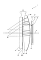
- FIG. 1 is a diagram illustrating a configuration of a peep-type wide-field image display device 1 according to an embodiment.
- FIG. 2 is a diagram illustrating a normal optical path.
- the wide-field image display device 1 illustrated in FIG. 1 is a wide-field image display device that is viewed by the user from the left side of FIG. 1 and used.
- the wide-field image display device 1 may be prepared for each of the user's right eye and left eye, or may be prepared only for one of the eyes. good. Further, the wide-field image display device 1 can be applied to, for example, a VR HMD.
- the wide-field image display device 1 includes an eyepiece optical system OC, a circular polarizing plate CP, and a display element D arranged in order from the user's eye side.
- the eyepiece optical system OC includes a first lens L1 and a second lens L2 arranged in order from the user's eye side.
- the first surface S1 which is the eye-side surface of the user in the first lens L1 is an aspherical surface.
- the reflective polarizing plate RP is, for example, a wire grid polarizing plate or a cholesteric polarizing plate.
- the third surface S3 may have an approximate plane around the optical axis A.
- the circular polarizing plate CP is laminated on the display element D.
- the circular polarizing plate CP is arranged in the space between the eyepiece optical system OC and the display element D (more specifically, between the half mirror HM and the display element D) without being laminated on the display element D. You may.
- the circular polarizing plate CP is, for example, a 1/4 wave plate superimposed on a linear polarizing plate.
- the display element D includes an image display surface S5 on which an image is displayed, a cover glass D1 for protecting the image display surface S5, and a display element substrate D2 for displaying an image on the image display surface S5.
- the display element D is a display panel having a large viewing angle, such as an OLED (Organic Light Emitting Diode) panel or a micro LED (Light Emitting Diode) panel.
- the image light emitted from the display element D follows the normal optical path (including the folded optical path) exemplified in FIG. 2 (and FIG. 1) as shown below, and is used. It is incident on the human eye (pupil).
- the image light emitted from the image display surface S5 of the display element D through the cover glass D1 first passes through the circular polarizing plate CP.
- the polarized state of the video light becomes a clockwise or counterclockwise circularly polarized state.
- the image light that has passed through the second lens L2 then passes through the 1/4 wave plate QWP.
- the polarization state of the video light changes from a clockwise or counterclockwise circular polarization state to a linear polarization state.
- the azimuth angle of the plane of polarization is set to 0 °.
- the image light that has passed through the 1/4 wave plate QWP is then reflected by the reflective polarizing plate RP.
- the reflective polarizing plate RP reflects the light in the linearly polarized state with an azimuth angle of 0 ° and transmits the light in the linearly polarized state with an azimuth angle of 90 °.
- the image light reflected by the reflective polarizing plate RP then passes through the 1/4 wave plate QWP again.
- the polarization state of the video light changes from the linear polarization state of the azimuth angle of 0 ° to the counterclockwise or clockwise circular polarization state.
- the image light that has passed through the 1/4 wave plate QWP then passes through the second lens L2 again in the order of the third surface S3 and the fourth surface S4. After that, a part of the video light that has passed through the fourth surface S4 of the second lens L2 is reflected by the half mirror HM, and the rest is transmitted through the half mirror HM and becomes unnecessary light.
- the video light reflected by the half mirror HM then passes through the second lens L2 again in the order of the fourth surface S4 and the third surface S3.
- the image light that has passed through the second lens L2 then passes through the 1/4 wave plate QWP again.
- the polarization state of the video light changes from the counterclockwise or clockwise circular polarization state to the linear polarization state with an azimuth angle of 90 °.
- the image light that has passed through the 1/4 wave plate QWP then passes through the reflective polarizing plate RP and passes through the first lens L1 in the order of the second surface S2 and the first surface S1. Then, the image light that has passed through the first lens L1 passes through the pupil surface S0 and is incident on the user's eye (pupil).
- the position of the pupil surface S0 is also the position of the assumed user's eye (pupil).
- the power of the eyepiece optical system OC is set to P0
- the power of the first lens L1 is set to P1
- the display element D is emitted to emit a second image light that follows the above-mentioned normal optical path.
- the power of the lens L2 is P2
- the relationship between P0 and P2 satisfies the following equation (1)
- the relationship between P1 and P2 satisfies the following equation (2).
- the optical axis A around the optical axis A on the third surface S3 of the second lens L2 is the power of the third surface S3 when the power P2 of the second lens L2 is 0.06 (unit: 1 / mm) or less.
- Is PW3, and the power due to the reflection on the user's eye side by the half mirror HM coated on the fourth surface S4 is PW4R, which is an approximate plane satisfying the following equation (3).
- the power P0 (unit: 1 / mm) of the eyepiece optical system OC satisfies the following formula (4). 0.05 ⁇ P0 ⁇ 0.075 Equation (4)
- the DD is also the diameter of the circle circumscribed by the display area of the image when the image is displayed on the image display surface S5. Further, the ED is also the diameter of a circle circumscribed by a region where the luminous flux of the image projected on the user's eye (pupil) passes through the second lens L2.
- the material of the second lens L2 is a resin material having a refractive index Nd satisfying the following formula (6) and an Abbe number Vd satisfying the following formula (7).
- Nd ⁇ 1.65 equation (6)
- Vd > 50 formula (7)
- the position of the pupil surface S0 is 12 mm from the first surface S1 of the first lens L1 toward the user's eye side, and the inclination of ⁇ with respect to the optical axis A is set to pass through the pupil surface S0.
- the main ray of possession is reversely tracked from the pupil surface S0 toward the first surface S1
- the main ray first incident on the third surface S3 of the second lens L2 is the optical axis A in the traveling direction.
- the main light ray emitted from the fourth surface S4 of the second lens L2 is inclined in a direction away from the optical axis A in the traveling direction.
- the angle of incidence of the main ray first incident on the third surface S3 with respect to the third surface S3 is set to ⁇ 3, and the fourth surface S4 of the main ray emitting out the fourth surface S4.
- ⁇ 3 satisfies the following equation (8)
- ⁇ 4 satisfies the following equation (9).
- the power P2 of the second lens L2 can be approximately obtained by the following equation (10).
- the power elements of PW4, PW3_1, PW3_2, PW4R, and PW3_3 are as follows. Note that PW3_1, PW3_2, and PW3_3 have the same value PW3.
- PW4 is the power due to refraction on the fourth surface S4 when the video light passing through the circular polarizing plate CP and passing through the half mirror HM is incident on the fourth surface S4.
- PW3_1 is the power due to refraction on the third surface S3 when the video light incident on the fourth surface S4 passes through the half mirror HM and exits the third surface S3.
- PW3_2 is the power due to bending on the third surface S3 when the image light reflected by the reflective polarizing plate RP and passing through the 1/4 wave plate QWP is incident on the third surface S3.
- the PW4R is the power generated by the reflection of the video light incident on the third surface S3 when it is reflected by the half mirror HM. This power can be calculated by the following equation (11-3) using the optical formula.
- PW3_3 is the power due to refraction on the third surface S3 when the image light reflected by the half mirror HM and incident on the fourth surface S4 exits the third surface S3.
- PW4 can be calculated by the following equation (11-1) using the optical formula.
- PW4 (1-Nd) ⁇ C4 equation (11-1)
- Nd is the refractive index of the second lens L2
- C4 is the curvature of the fourth surface S4.
- PW3_1, PW3_2, and PW3_3 have the same value PW3.
- This power can be calculated by the following equation (11-2) using the optical formula.
- PW3 (Nd-1) ⁇ C3 equation (11-2)
- C3 is the curvature of the third surface S3.
- PW4R can be calculated by the following equation (11-3) using the optical formula.
- PW4R -2 x Nd x C4 formula (11-3)
- each power element on the right side of the above equation (10) has a positive value. From this, the power that the second lens L2 needs to bear is obtained by synthesizing relatively small power elements.
- the fourth surface S4 can produce a PW4R of a required size with a particularly loose curvature.
- the second lens L2 is composed of a convex surface having a loose curvature, and can generate a large power satisfying the above equations (1) and (4), so that the occurrence of aberration can be suppressed to a small extent.
- the second lens L2 can produce the required power even if the lens is made of a material having a relatively small refractive index Nd. Therefore, as the material of the second lens L2, a material having a large Abbe number Vd, that is, a material having a small dispersion can be selected. By selecting a material having a small dispersion, the occurrence of chromatic aberration of the second lens L2 can be suppressed to a low level.
- the material of the second lens L2 is preferably selected from the materials included in the range satisfying the above formulas (6) and (7). Then, by selecting the injection-moldable resin material included in this range, the second lens L2 can be manufactured easily and at low cost.
- the third surface S3 of the second lens L2 and the first surface S1 of the first lens L1 are both aspherical surfaces and face the air, they have a large aberration correction effect.
- the surface can correct the aberration of the entire OC of the eyepiece optical system to a practically sufficient level.
- the power of the second lens L2 is almost the same as the power P0 of the eyepiece lens, that is, the second lens L2.
- the power required for the lens may be 0.06 (unit: 1 / mm) or less.
- this power is a magnitude that can be reasonably produced only by PW4R calculated by the above equation (11-3).
- the third surface S3, which is an aspherical surface may be an approximate plane whose shape around the optical axis A is close to a plane as long as the above equation (3) is satisfied.
- the above equation (12) can be expressed as the following equation (13), and the power P1 of the first lens L1 has a negative value.
- the above equation (12) can be expressed as the following equation (14).
- the power P0 of the eyepiece optical system OC is increased in order to create a large FOV from the small display element D, the focal length becomes shorter. Therefore, sufficient eye relief is secured for the eyepiece optical system OC and the display element D is used. In order to secure the distance, it is important to satisfy the above equations (13) and (14) as described below.
- the focal length of the eyepiece OC is as short as less than 20 mm, and therefore, when the power of the first lens L1 exceeds a certain value, it becomes difficult to secure eye relief.
- the rear side of the eyepiece optical system OC is obtained.
- the focal position moves toward the inside of the eyepiece optical system OC. Therefore, when the positive power of the first lens L1 with respect to the second lens L2 exceeds a certain limit, the posterior focal position slips into the inside of the eyepiece optical system OC. Since it is necessary to project a virtual image from a distance, it is necessary to arrange the image display surface S5 of the display element D near the focal position on the rear side of the eyepiece optical system OC.
- the posterior focal position of the eyepiece optical system OC is located on the outer side of the eyepiece optical system OC (in FIG. 1 or FIG. 2) with respect to the fourth surface S4 of the second lens L2. Must be on the right side of).
- the first lens L1 has a negative power
- the stronger the negative power of the first lens L1 the larger the luminous flux diameter of the image light passing through the second lens L2.
- the second lens L2 needs to cancel the negative power of the first lens L1, it is necessary to strengthen the positive power. Therefore, when the negative power of the first lens L1 exceeds a certain limit, the image peripheral light that should pass through the second lens L2 and head toward the display element D is the fourth lens L2 of the second lens L2. Total internal reflection occurs on the surface S4.
- the second surface S2 is a plane or an approximate plane
- the first surface S1 is an aspherical surface.
- This aspherical surface becomes stronger toward the outer periphery in the negative direction in order to correct the tangier field curvature generated in the negative direction in the second lens L2, and therefore, in a particularly large FOV, the first The outer periphery of the surface S1 protrudes toward the user's eye (see, for example, FIG. 1).
- the stronger the negative power of the first lens L1 the larger the amount of protrusion thereof, and the more likely it is that interference with the user's face occurs.
- the first surface S1 is an aspherical surface and has an important function of canceling the aberration generated in the second lens L2.
- the power is not appropriately set. There arises a problem that sufficient eye relief cannot be secured and the distance between the second lens L2 and the display element D cannot be secured.
- these problems can be avoided by satisfying the above equations (13) and (14).
- the first lens L1 is thin and has little eye relief loss.
- the second surface S2 of the first lens L1 is a plane or an approximate plane, even if the reflective polarizing plate RP and the 1/4 wave plate QWP are laminated on the surface, the surface may be laminated. The adhesion can be kept good.
- the diameter of the laminated surface of the second surface S2 on which the reflective polarizing plate RP and the 1/4 wave plate QWP are laminated is DL, and the maximum value of the sag of the second surface S2 is SL, it is a plane or an approximate plane.
- the second surface S2 is a plane, a spherical surface, or an aspherical surface satisfying the following equation (16). 0.05 ⁇ DL >
- the four-wavelength film) QWP can be laminated on the second surface S2 by expanding and contracting the circumferential dimension by about 0.6%. This degree of expansion and contraction is a reasonable value if it is a reflective polarizing plate (reflection polarizing film) RP and a 1/4 wave plate (1/4 wave film) QWP using a resin film as a base material.
- FIG. 3 is a diagram illustrating straight light.
- the straight light is light that emits the display element D and passes through the pupil S0 without following the normal optical path (that is, never reflecting) as illustrated in FIG. 2 (and FIG. 1), and generates a ghost. It is a stray light to get.
- the second lens L2 is made of a material having a small birefringence, and since the retardation is proportional to the birefringence and the optical path length, the internal stress remains and the birefringence is caused by the photoelastic effect. It is important to shorten the optical path length of the peripheral portion of the lens, which tends to appear frequently, and the second lens L2, in which both the third surface S3 and the fourth surface S4 have a convex shape, has a shape suitable for this. There is.
- the straight light that emits the display element D passes through the eyepiece optical system OC without being reflected even once, and passes through the pupil S0, including the dependent light beam, is the display element. It is convergent light from D toward the user's eye side, and the size of the passing region in the second lens L2 of this light beam is smaller than the size of the image displayed on the image display surface S5.
- the straight light emitted from the image display surface S5 and passing through the pupil surface S0 causes the second lens L2 to have a large birefringence. Avoid the surrounding area and pass through. From this, the permissible amount of birefringence in the peripheral portion of the second lens L2 can be greatly relaxed.
- the retardation is preferably 10 nm or less in the central portion of the second lens L2, but there is no problem even if the peripheral portion is about several tens of nm.
- the third surface S3 of the second lens L2 is an aspherical surface
- molding is preferable as the manufacturing method in consideration of mass productivity.
- thermal stress remains in the peripheral portion of the lens, and there is a strong tendency for birefringence to increase due to the photoelastic effect.
- the resin material used at this time include Optimas (registered trademark) of Mitsubishi Gas Chemicals, Inc., AZP (registered trademark) announced by Asahi Kasei Corporation in 2014, APEL (registered trademark) of Mitsui Chemicals, Inc., etc.
- Resin materials such as can be used. All of these are acrylic materials satisfying the above formulas (6) and (7).
- the wide-field image display device 1 satisfies the above equation (4).
- the reason why the power P0 of the eyepiece optical system OC is less than 0.075 (unit: 1 / mm) is that the second lens L2 can produce strong power with a single lens, but the stronger the power, the more aberrations increase. This is because the aberration becomes remarkably large especially when it exceeds 0.075 (unit: 1 / mm).
- the power of the optical system OC is 0.05 (unit: 1 / mm) or less, the DD (maximum size of the image displayed on the image display surface S5) on the left side in the above equation (5) becomes too large. This is because it becomes difficult to satisfy the above equation (5).
- EFL is the focal length of the eyepiece optical system OC.
- Dis (unit:%) is a percentage distortion at the image edge portion of the eyepiece optical system OC defined by the following formula (18).
- Dis (actual maximum image height-ideal maximum image height) / (ideal maximum image height) x 100 equation (18) FOV is the viewing angle of the eyepiece optical system OC.
- DD the maximum size of the image displayed on the image display surface S5.
- DD / 2 is the image height of the image.
- an eyepiece optical system having a negative Dis can reduce the power of the eyepiece optical system as compared with an eyepiece optical system without a Dis. For example, if Dis is -30%, the power of the eyepiece optical system can be reduced by 30% as compared with the case without Dis.
- the power of the eyepiece optical system OC and the power of the second lens L2 are substantially the same, it can be said that the power of the second lens L2 can be reduced by about 30%.
- the second lens L2 can produce a strong power, but the stronger the power, the larger the aberration. Therefore, in order to obtain excellent resolution performance, it is preferable that the power of the second lens L2 is small. In particular, when the power of the second lens L2 is 0.075 (unit: 1 / mm) or more, the aberration becomes remarkably large.
- the negative Dis can realize the eyepiece optical system OC with higher resolution performance while maintaining the FOV.
- the negative Dis can realize a larger FOV eyepiece optical system OC while maintaining the resolution performance.
- the position of the pupil surface S0 is assumed to be a position 12 mm from the first surface S1 of the first lens L1, and the optical axis A passes through the pupil surface S0.
- the main ray having an inclination of ⁇ is reversely tracked from the pupil surface S0 toward the first surface S1
- the main ray first incident on the third surface S3 of the second lens L2 travels in the traveling direction.
- the main light ray emitted from the fourth surface S4 of the second lens L2 is inclined toward the optical axis A toward the direction of travel toward the optical axis A.
- FIG. 4 is a diagram illustrating a main ray passing through the pupil surface S0 and having an inclination of ⁇ with respect to the optical axis A.
- the main ray CR4 emitted from the fourth surface S4 of the second lens L2 travels in the traveling direction. Since the fourth surface S4 is inclined toward the optical axis A and has a convex shape toward the display element D, the emission angle ⁇ 4 from the fourth surface S4 of the main ray CR4 is clockwise. Has a large angle. For this reason, a large negative spherical aberration is generated in the main ray on the fourth surface S4.
- the main ray CR3 first incident on the third surface S3 of the second lens is inclined in a direction away from the optical axis A in the traveling direction, and the third surface S3 is used around the optical axis A. Since it has a convex shape or an approximate plane toward the eye of a person, the angle of incidence ⁇ 3 of the main ray CR3 on the third surface S3 has a clockwise angle. For this reason, negative spherical aberration is generated in the main ray on the third surface S3. In particular, when the third surface S3 has a convex shape toward the eye of the user, the incident angle ⁇ 3 becomes large, and a large negative spherical aberration occurs.
- the height of the main light beam emitted at 40 °) across the image display surface S5 of the display element D can be lowered. That is, the action of creating a negative Dis is born. As described above, this is preferable for designing a large FOV eyepiece optical system OC while maintaining the resolution performance.
- the position of the pupil surface S0 is assumed to be 12 mm from the first surface S1 of the first lens L1 is that ⁇ 3 and ⁇ 4 change when the position of the pupil surface S0 changes, so that ⁇ 3 and ⁇ 4 This is because it is necessary to assume the position of the pupil surface S0 in order to quantitatively define.
- the spectacles are adjusted so that the distance between the eye and the spectacle lens is 12 mm. This is to prevent the spectacle lens from being soiled by the splash of tears generated by blinking. Even in the wide-field image display device 1, it is preferable to increase the distance between the eyepiece optical system OC and the eye by 12 mm or more.
- the third surface S3 of the second lens L2 has a convex shape or an approximate plane
- the fourth surface S4 has a convex shape. It has substantially five positive power elements (see equation (10) above) due to the folded optical path created by utilizing polarization and reflection.
- the second lens L2 can generate a strong positive power on a convex surface having a gentle curvature, and can suppress the occurrence of aberration.
- a sufficiently strong positive power can be produced by using a material having a low refractive index, a material having a low dispersion can be selected and the occurrence of chromatic aberration can be suppressed.
- first surface S1 of the first lens L1 and the third surface S3 of the second lens L2 are aspherical surfaces facing the air, and the fact that they face the air means that their interfaces are refracted. Since the rate difference is large, the first surface S1 and the third surface S3 can strongly correct aberrations even if they have a relatively gentle aspherical shape. Therefore, it is possible to design an eyepiece optical system OC having excellent resolving power, and it is possible to reduce the sag and make the eyepiece optical system OC thinner.
- both the third surface S3 and the fourth surface S4 of the second lens L2 have a convex shape, a large incident angle ⁇ 3 and an emission angle ⁇ 4 of the main ray can be obtained, and negative image distortion is obtained in the reverse tracking. To create. As a result, a large FOV image can be projected from the display element D having a small image display surface size while suppressing the power of the second lens L2. Further, the size of the image display surface can be designed to be smaller than the outer diameter of the second lens L2.
- the stray light traveling straight in the eyepiece optical system OC travels in the second lens L2 while avoiding the peripheral portion of the lens where birefringence is likely to occur, and thus the compound in the outer peripheral portion of the second lens L2.
- the allowable amount of refraction can be increased, and the second lens L2 can be manufactured by molding the resin. According to the molding, even an aspherical lens can be manufactured at low cost.
- the power distribution between the first lens L1 and the second lens L2 enables a design that secures sufficient eye relief and avoids buffering between the eyepiece optical system OC and the display element D.
- a wide-field (FOV of 80 ° or more) and high-resolution images can be visually recognized by the user, and the image is compact (thin) and lightweight. The effects of excellent mass productivity and low manufacturing cost can be obtained.
- the case where the optical axis A of the third surface S3 of the second lens L2 is convex toward the user's eyes is specified.
- An example is shown as Example 1
- a specific example in the case where the optical axis A of the third surface S3 of the second lens L2 is an approximate plane is shown as Example 2.
- the configuration table shown in each embodiment is numbered serially in the direction of tracing the optical path of the video light in the reverse direction. Further, in each embodiment, the optical specifications and the performance are shown by tracing the optical path in the reverse direction in view of the law of light reversal.
- the material of the second lens L2 is Optimas (registered trademark) 7500 of Mitsubishi Gas Chemical Company, Inc.
- the wide-field image display device 1 has an inclination of ⁇ (40 °) with respect to the optical axis A through its configuration, a normal optical path, a straight optical path capable of generating a ghost, and a pupil surface S0.
- the main ray is the same as that shown in FIGS. 1, 2, 3, and 4.
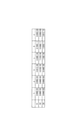
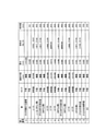
- FIG. 5 is a diagram illustrating a configuration table relating to an optical system of the wide-field image display device 1 according to the first embodiment.
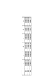
- FIG. 6 is a diagram illustrating the coefficients of the aspherical equation according to the first embodiment.
- the configuration table exemplified in FIG. 5 shows the type of the surface corresponding to each serial number, the radius of curvature around the optical axis A, the thickness around the optical axis A, the material (Nd, Vd), and the effective diameter.
- the sag of each aspherical surface can be obtained by the aspherical equation of the following equation (23).
- Y (unit: mm) is a distance from the optical axis A.
- R (unit: mm) is the radius of curvature around the optical axis A.
- Sag (unit: mm) is the coordinates in the optical axis A direction when the center of the optical axis of the surface in Y is the origin.
- the coefficients k, a, b, c, d, and e for each aspherical surface are as shown in FIG.
- P0, P1, P2, PW3, and PW4R are as follows.
- the above equations (1) and (2) are satisfied, and the above equation (4) is also satisfied.
- the material of the second lens L2 is Optimas (registered trademark) 7500 of Mitsubishi Gas Chemical Company, Inc., which also satisfies the above formulas (6) and (7).
- the FOV, DD, Dis, ⁇ 3, and ⁇ 4 are as follows.
- the DD is 22.8 mm
- the above formula (5) is also satisfied from the effective diameter of the second lens L2 in the configuration table shown in FIG. Further, since ⁇ 3 is 42.9 ° and ⁇ 4 is 35.3 °, both the above equations (8) and (9) are satisfied.
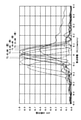
- FIG. 7 a graph showing the relationship between the focal movement and the absolute value of the OTF (Optical Transfer Function) is illustrated in FIG. 7, and the relationship between the curvature of field and the viewing angle is illustrated.
- FIG. 8 exemplifies a graph showing the above and a graph showing the relationship between the percentage distortion and the viewing angle.
- the graph illustrated in FIG. 7 is for a case where the spatial frequency is 40 cycles / mm, the wavelength is 525 ⁇ m, the pupil diameter is 4 mm, and the pupil position is 15 mm.
- the graph illustrated in FIG. 8 is for the case where the pupil position is 15 mm. Both graphs show that the resolution performance of the eyepiece optical system OC according to the first embodiment is good.
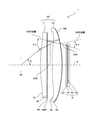
- FIG. 9 is a diagram illustrating the configuration of the wide-field video display device 1 according to the second embodiment.
- FIG. 10 is a diagram illustrating a normal optical path according to the second embodiment.
- FIG. 11 is a diagram illustrating a straight optical path capable of generating a ghost according to the second embodiment.
- FIG. 12 is a diagram illustrating a main ray passing through the pupil surface S0 and having an inclination of ⁇ with respect to the optical axis A in the second embodiment.
- the optical axis A of the third surface S3 of the second lens L2 is an approximate plane.
- the normal optical path becomes an optical path as exemplified in FIG. 10 (and FIG. 9), and the straight optical path capable of generating a ghost becomes an optical path as exemplified in FIG.
- the main ray passing through the pupil surface S0 and having an inclination of ⁇ (40 °) with respect to the optical axis A is as illustrated in FIG.
- FIG. 13 is a diagram illustrating a configuration table relating to an optical system of the wide-field image display device 1 according to the second embodiment.
- FIG. 14 is a diagram illustrating the coefficients of the aspherical equation according to the second embodiment.
- the sag of each aspherical surface can be obtained by the aspherical surface equation of the above equation (23).
- the coefficients k, a, b, c, d, and e for each aspherical surface are as shown in FIG.
- P0, P1, P2, PW3, and PW4R are as follows.
- P2 0.94 x P0,
- 0.16 ⁇ P2,
- P2 0.06 (unit: 1 / mm) or less, and from each value of PW3 and PW4R, the circumference of the optical axis A on the third surface S3 is an approximate plane satisfying the above equation (3). It has become.
- the material of the second lens L2 is Optimas (registered trademark) 7500 of Mitsubishi Gas Chemical Company, Inc., as in Example 1, and the above formulas (6) and (7) are also satisfied.
- the FOV, DD, Dis, ⁇ 3, and ⁇ 4 are as follows.
- the DD is 12.0 mm
- the above formula (5) is also satisfied from the effective diameter of the second lens L2 in the configuration table exemplified in FIG. Further, since ⁇ 3 is 38.4 ° and ⁇ 4 is 28.3 °, the above formula (8) is satisfied although the above formula (9) is not satisfied.
- FIG. 15 a graph showing the relationship between the focal movement and the absolute value of OTF is illustrated in FIG. 15, and the graph showing the relationship between the curvature of field and the viewing angle and the percentage are shown.
- a graph showing the relationship between the distortion and the viewing angle is illustrated in FIG.
- the graph illustrated in FIG. 15 is for a case where the spatial frequency is 40 cycles / mm, the wavelength is 525 ⁇ m, the pupil diameter is 4 mm, and the pupil position is 15 mm.
- the graph illustrated in FIG. 16 is for the case where the pupil position is 15 mm. Both graphs show that the resolution performance of the eyepiece optical system OC according to the second embodiment is good.
- the present invention is not limited to the above embodiment as it is, and at the implementation stage, the components can be modified and embodied within a range that does not deviate from the gist thereof.
- various inventions can be formed by an appropriate combination of the plurality of components disclosed in the above-described embodiment. For example, some components of all the components shown in the embodiment may be deleted. In addition, components across different embodiments may be combined as appropriate.
Landscapes
- Physics & Mathematics (AREA)
- General Physics & Mathematics (AREA)
- Optics & Photonics (AREA)
- Engineering & Computer Science (AREA)
- Multimedia (AREA)
- Signal Processing (AREA)
- Lenses (AREA)
Abstract
覗き込み型の広視野映像表示装置は、使用者の眼側から順に配置された接眼光学系(OC)、円偏光板、表示素子(D)を備え、OCは、使用者の眼側から順に配置された第1のレンズ(L1)、第2のレンズ(L2)を含み、L1における使用者の眼側の面は非球面であり、L1におけるD側の面は平面又は近似平面であり且つ反射偏光板及び1/4波長板が当該順に使用者の眼側からラミネートされ、L2における使用者の眼側の面は非球面であってOCの光軸回りが使用者の眼側に凸形状又は近似平面であり、L2におけるD側の面はD側に凸形状の非球面であり且つハーフミラーがコートされ、OC、L1のパワーをP0、P1とし、Dを出射して正規光路を辿る映像光に対するL2のパワーをP2とすると、0.8×P0≦P2≦1.2×P0、|P1|<1/4×P2、である。
Description
本発明は、折り返し光路を有する覗き込み型の広視野映像表示装置に関する。
近年、覗き込み型の広視野映像表示装置の一例として、VR(Virtual Reality)用途が想定されたHMD(Head Mounted Display)(以下、「VR用HMD」という)が注目され始めている。
VR用HMDは、VR用途が特に想定されていない通常のHMDに比べて、FOV(Field Of View)(「視野角」ともいう)が広い。例えば、通常のHMDのFOVが45°以下が一般的であるが、VR用HMDのFOVは90°以上であることが多い。FOVが45°に対して90°を比較すると、FOVの値は2倍であるが、バーチャルスクリーンの直径では2.4倍、その面積では5.8倍にもなる。そのため、VR用HMDでは、より高い臨場感を使用者に生じさせることができる。なお、臨場感は、映像の最大画角(視野角)の増加に伴って高まり、80°付近以上から飽和することが非特許文献1に示されている。
このようなVR用HMDに適用され得る光学システムとして、例えば、特許文献1、2に記載の光学システムが知られている。
畑田豊彦,坂田晴夫,日下秀夫著、「画面サイズによる方向感覚誘導効果」、テレビジョン学会誌、Vol.33、(1979)、No.5、P.407-413
VR用HMDのような覗き込み型の広視野映像表示装置においては、広視野(FOVが80°以上)且つ高解像度の映像を使用者に視認させることができること、小型(薄型)軽量であること、量産性に優れていること、及び製造コストが低いことが望まれている。
しかしながら、これらの要望の全てに応えられるものは未だ実現されていないのが実状である。例えば、特許文献1に記載の光学システムを適用して覗き込み型の広視野映像表示装置を実現する場合は、次のような課題が残る。
特許文献1に記載の光学システムでは、反射偏光子が、光学レンズの湾曲した主表面上に配置されている。このように反射偏光子を湾曲面上に配置するためには特殊な製法が必要であり、コストアップ、更には信頼性にも課題が残る。
リターダ層を湾曲面上に配置することは製法上困難であり、特許文献1に記載の光学システムでは、リターダ層が、像を放射するイメージャ(いわゆる表示パネル)側の光学レンズの平坦又は実質的に平坦な主表面上に配置されている。このために、表示パネル側の光学レンズは、リターダ層が配置される主表面をサグの大きな非球面に構成して光線収差を補正することができない。有効に収差を補正する手段を失った当該レンズは、パワーを強くできない。パワーを強くすると収差が増えるが、それを打ち消すことが出来ないためである。その結果、特許文献1に記載の光学システムは、倍率が限定的になる。そしてそのため、大きなFOV(80°以上)を得るためには、表示パネルのサイズを大きくする必要があり、これにより次の2つの課題が残る。
1.表示パネルのサイズが大きくなると、装置全体が大きくなり、重くなる。
2.表示パネルのサイズが大きくなると、その表示面を出射し、正規の光路を辿らずに(即ち一度も反射せずに)ストレートに通過する光束(有害光束)は、特に表示面に隣接する光学レンズ内で太くなる。そして、その光線を遮断して明瞭な映像を得るためには、当該光学レンズの光束が通過する領域全体に渡りその複屈折を小さくする必要がある。プラスチックレンズは周辺部で複屈折が発生しやすいため、当該光学レンズにプラスチックレンズを用いることはできず、ガラスレンズを用いざるを得ない。しかしながら、ガラスレンズは、プラスチックレンズに比べて製造コストが高く、特に非球面レンズはそれが顕著である。しかもガラスレンズはプラスチックレンズよりも重い。また、ガラスレンズであっても、例えばモールディングにより製造すると、レンズ周辺部で複屈折が大きくなり、製造方法に工夫が必要になる。
このような課題は、特許文献2に記載の光学システムを適用して覗き込み型の広視野映像表示装置を実現する場合にも同様に生じ得る。
本発明は、上記実状に鑑み、広視野(FOVが80°以上)且つ高解像度の映像を使用者に視認させることができると共に、小型(薄型)軽量で、量産性に優れ、製造コストが低い覗き込み型の広視野映像表示装置を提供することを目的とする。
本発明は、上記実状に鑑み、広視野(FOVが80°以上)且つ高解像度の映像を使用者に視認させることができると共に、小型(薄型)軽量で、量産性に優れ、製造コストが低い覗き込み型の広視野映像表示装置を提供することを目的とする。
本発明の一態様は、覗き込み型の広視野映像表示装置であって、使用者の眼側から順に配置された接眼光学系、円偏光板、及び表示素子を備え、前記接眼光学系は、前記使用者の眼側から順に配置された第1のレンズ及び第2のレンズを含み、前記第1のレンズにおける前記使用者の眼側の面である第1の面は、非球面であり、前記第1のレンズにおける表示素子側の面である第2の面は、平面又は近似平面であり、且つ、反射偏光板及び1/4波長板が当該順に前記使用者の眼側からラミネートされており、前記第2のレンズにおける前記使用者の眼側の面である第3の面は、非球面であって前記接眼光学系の光軸回りが前記使用者の眼側に凸形状又は近似平面であり、前記第2のレンズにおける前記表示素子側の面である第4の面は、前記表示素子側に凸形状の非球面であり、且つ、ハーフミラーがコートされており、前記接眼光学系のパワーをP0とし、前記第1のレンズのパワーをP1とし、前記表示素子を出射して正規光路を辿る映像光に対する前記第2のレンズのパワーをP2とすると、0.8×P0≦P2≦1.2×P0、|P1|<1/4×P2、である、ことを特徴とする。
本発明によれば、広視野(FOVで80°以上)且つ高解像度の映像を使用者に視認させることができると共に、小型(薄型)軽量で、量産性に優れ、製造コストが低い覗き込み型の広視野映像表示装置を提供することができる。
以下、図面を参照しながら、本発明の実施の形態について説明する。
図1は、一実施の形態に係る覗き込み型の広視野映像表示装置1の構成を例示する図である。図2は、正規光路を例示する図である。
図1は、一実施の形態に係る覗き込み型の広視野映像表示装置1の構成を例示する図である。図2は、正規光路を例示する図である。
図1に例示した広視野映像表示装置1は、図1の左側から使用者により覗き込まれて使用される広視野映像表示装置である。なお、広視野映像表示装置1は、使用者の右眼用と左眼用のそれぞれに用意されるものであってもよいし、いずれか片方の眼用のみに用意されるものであってもよい。また、広視野映像表示装置1は、例えばVR用HMDに適用され得る。
広視野映像表示装置1は、使用者の眼側から順に配置された接眼光学系OC、円偏光板CP、及び表示素子Dを含む。接眼光学系OCは、使用者の眼側から順に配置された第1のレンズL1及び第2のレンズL2を含む。
第1のレンズL1における使用者の眼側の面である第1の面S1は、非球面である。第1のレンズL1における表示素子D側の面である第2の面S2は、平面又は近似平面である。また、第2の面S2は、反射偏光板(反射偏光フィルム)RP及び1/4波長板(1/4波長フィルム)QWPが当該順に使用者の眼側からラミネートされている。反射偏光板RPは、例えば、ワイヤグリッド偏光板又はコレステリック偏光板である。
第2のレンズL2における使用者の眼側の面である第3の面S3は、非球面であり、接眼光学系OCの光軸A回りが使用者の眼側に凸形状である。あるいは、第3の面S3は、光軸A回りが近似平面であってもよい。第2のレンズL2における表示素子D側の面である第4の面S4は、非球面であり、表示素子D側に凸形状である。また、第4の面S4は、ハーフミラー(半透過鏡)HMがコートされている。
円偏光板CPは、表示素子Dにラミネートされている。あるいは、円偏光板CPは、表示素子Dにラミネートされることなく、接眼光学系OCと表示素子Dとの間(より詳しくは、ハーフミラーHMと表示素子Dとの間)の空間に配置されてもよい。円偏光板CPは、例えば、直線偏光板の上に1/4波長板を重ね合わせたものである。
表示素子Dは、映像が表示される映像表示面S5と、映像表示面S5を保護するカバーガラスD1と、映像表示面S5に映像を表示させる表示素子基板D2とを含む。表示素子Dは、例えば、OLED(Organic Light Emitting Diode)パネル、又は、マイクロLED(Light Emitting Diode)パネルといった視野角が大きな表示パネルである。
このような構成の広視野映像表示装置1では、表示素子Dから出射した映像光が、次のような図2(及び図1)に例示した正規光路(折り返し光路を含む)を辿って、使用者の眼(瞳孔)に入射する。
図2(及び図1)に例示したように、表示素子Dの映像表示面S5からカバーガラスD1を介して出射した映像光は、まず、円偏光板CPを通過する。これにより、映像光の偏光状態が、右回り又は左回りの円偏光状態になる。
円偏光板CPを通過した映像光は、その後、一部がハーフミラーHMを透過し、残りがハーフミラーHMで反射して不要光となる。
ハーフミラーHMを透過した映像光は、その後、第2のレンズL2を、第4の面S4、第3の面S3の順に、通過する。
ハーフミラーHMを透過した映像光は、その後、第2のレンズL2を、第4の面S4、第3の面S3の順に、通過する。
第2のレンズL2を通過した映像光は、その後、1/4波長板QWPを通過する。これにより、映像光の偏光状態が、右回り又は左回りの円偏光状態から直線偏光状態になる。ここでは、その偏光面の方位角を0°と置くことにする。
1/4波長板QWPを通過した映像光は、その後、反射偏光板RPで反射する。ここでは、反射偏光板RPが、方位角0°の直線偏光状態の光を反射し、方位角90°の直線偏光状態の光を透過するものとする。
反射偏光板RPで反射した映像光は、その後、1/4波長板QWPを再び通過する。これにより、映像光の偏光状態が、方位角0°の直線偏光状態から左回り又は右回りの円偏光状態になる。
1/4波長板QWPを通過した映像光は、その後、第2のレンズL2を、第3の面S3、第4の面S4の順に、再び通過する。
第2のレンズL2の第4の面S4を通過した映像光は、その後、一部がハーフミラーHMで反射し、残りがハーフミラーHMを透過して不要光となる。
第2のレンズL2の第4の面S4を通過した映像光は、その後、一部がハーフミラーHMで反射し、残りがハーフミラーHMを透過して不要光となる。
ハーフミラーHMで反射した映像光は、その後、第2のレンズL2を、第4の面S4、第3の面S3の順に、再び通過する。
第2のレンズL2を通過した映像光は、その後、1/4波長板QWPを再び通過する。これにより、映像光の偏光状態が、左回り又は右回りの円偏光状態から方位角90°の直線偏光状態になる。
第2のレンズL2を通過した映像光は、その後、1/4波長板QWPを再び通過する。これにより、映像光の偏光状態が、左回り又は右回りの円偏光状態から方位角90°の直線偏光状態になる。
1/4波長板QWPを通過した映像光は、その後、反射偏光板RPを透過し、第1のレンズL1を、第2の面S2、第1の面S1の順に、通過する。そして、第1のレンズL1を通過した映像光は、瞳面S0を通過し、使用者の眼(瞳孔)に入射する。なお、瞳面S0の位置は、想定される使用者の眼(瞳孔)の位置でもある。
また、広視野映像表示装置1では、接眼光学系OCのパワーをP0とし、第1のレンズL1のパワーをP1とし、表示素子Dを出射して上述の正規光路を辿る映像光に対する第2のレンズL2のパワーをP2とすると、P0とP2の関係は下記式(1)を満たし、P1とP2の関係は下記式(2)を満たしている。
0.8×P0≦P2≦1.2×P0 式(1)
|P1|<1/4×P2 式(2)
0.8×P0≦P2≦1.2×P0 式(1)
|P1|<1/4×P2 式(2)
また、第2のレンズL2の第3の面S3における光軸A回りは、第2のレンズL2のパワーP2が0.06(単位:1/mm)以下の場合、第3の面S3のパワーをPW3とし、第4の面S4にコーティングされているハーフミラーHMでの使用者の眼側への反射によるパワーをPW4Rとすると、下記式(3)を満たす近似平面である。
|PW3|>―1/10×PW4R 式(3)
|PW3|>―1/10×PW4R 式(3)
また、接眼光学系OCのパワーP0(単位:1/mm)は、下記式(4)を満たしている。
0.05<P0<0.075 式(4)
0.05<P0<0.075 式(4)
また、表示素子Dの映像表示面S5に表示される映像の最大サイズをDDとし、第2のレンズL2の有効径をEDとすると、DDとEDの関係は、下記式(5)を満たしている。
DD<0.8×ED 式(5)
DD<0.8×ED 式(5)
なお、DDは、映像が映像表示面S5に表示されたときの、その映像の表示領域が外接する円の直径でもある。また、EDは、使用者の目(瞳孔)に投影される映像の光束が第2のレンズL2を通過する領域が外接する円の直径でもある。
また、好ましくは、第2のレンズL2の材料は、屈折率Ndが下記式(6)を満たし、アッベ数Vdが下記式(7)を満たす、樹脂材料である。
Nd<1.65 式(6)
Vd>50 式(7)
Nd<1.65 式(6)
Vd>50 式(7)
また、瞳面S0の位置を第1のレンズL1の第1の面S1から使用者の眼側へ12mmの位置と仮定し、瞳面S0を通過して光軸Aに対してθの傾きを持つ主光線を瞳面S0から第1の面S1に向かって逆追跡をしたとき、最初に第2のレンズL2の第3の面S3に入射する主光線は、進行方向に向かって光軸Aから離れる方向に傾いており、第2のレンズL2の第4の面S4を出射する主光線は、進行方向に向かって光軸Aに近づく方向に傾いている。
例えば、θが40°の場合、最初に第3の面S3に入射する主光線の第3の面S3に対する入射角をθ3とし、第4の面S4を出射する主光線の第4の面S4に対する出射角をθ4とすると、θ3が下記式(8)を満たしている、及び又は、θ4が下記式(9)を満たしている。
|θ3|>30° 式(8)
|θ4|>30° 式(9)
|θ3|>30° 式(8)
|θ4|>30° 式(9)
以下、このような構成の広視野映像表示装置1の作用、効果について詳細に説明する。なお、以下では、特に断りが無い限り、使用者の眼側から表示素子D側へ光線を追跡する逆追跡を前提に説明を行う。
広視野映像表示装置1では、上記式(1)、(2)を満たしていることから明らかなように、接眼光学系OCのパワーの大部分を、主に第2のレンズL2が担っている。
上述の正規光路(折り返し光路を含む)における第2のレンズL2に関わる光路に着目すると、第2のレンズL2のパワーP2は、下記式(10)により近似的に求められる。
上述の正規光路(折り返し光路を含む)における第2のレンズL2に関わる光路に着目すると、第2のレンズL2のパワーP2は、下記式(10)により近似的に求められる。
P2≒PW4+PW3_1+PW3_2+PW4R+PW3_3 式(10)
ここで、PW4、PW3_1、PW3_2、PW4R、PW3_3の各パワー要素は、次のとおりである。なお、PW3_1、PW3_2、PW3_3は、同じ値PW3になる。
ここで、PW4、PW3_1、PW3_2、PW4R、PW3_3の各パワー要素は、次のとおりである。なお、PW3_1、PW3_2、PW3_3は、同じ値PW3になる。
PW4は、円偏光板CPを通過してハーフミラーHMを透過した映像光が第4の面S4に入射したときの、当該第4の面S4での屈折によるパワーである。
PW3_1は、第4の面S4に入射した映像光がハーフミラーHMを透過して、第3の面S3を出射したときの、当該第3の面S3での屈折によるパワーである。
PW3_1は、第4の面S4に入射した映像光がハーフミラーHMを透過して、第3の面S3を出射したときの、当該第3の面S3での屈折によるパワーである。
PW3_2は、反射偏光板RPで反射して1/4波長板QWPを通過した映像光が第3の面S3に入射したときの、当該第3の面S3での屈曲によるパワーである。
PW4Rは、第3の面S3に入射した映像光が、ハーフミラーHMで反射したときの、当該ハーフミラーHMでの反射によるパワーである。このパワーは光学の公式を用い下記式(11-3)で計算できる。
PW4Rは、第3の面S3に入射した映像光が、ハーフミラーHMで反射したときの、当該ハーフミラーHMでの反射によるパワーである。このパワーは光学の公式を用い下記式(11-3)で計算できる。
PW3_3は、ハーフミラーHMで反射して第4の面S4に入射した映像光が第3の面S3を出射したときの、当該第3の面S3での屈折によるパワーである。
なお、PW4は、光学の公式を用いて下記式(11-1)で計算できる。
PW4=(1-Nd)×C4 式(11-1)
ここで、Ndは第2のレンズL2の屈折率、C4は第4の面S4の曲率である。
PW3_1、PW3_2、PW3_3は、同じ値PW3になる。このパワーは光学の公式を用い下記式(11-2)で計算できる。
PW3=(Nd-1)×C3 式(11-2)
ここで、C3は第3の面S3の曲率である。
PW4Rは、光学の公式を用い下記式(11-3)で計算できる。
PW4R=-2×Nd×C4 式(11-3)
第2のレンズL2は、第3の面S3と第4の面S4とが共に凸形状であるため、上記式(10)の右辺の各パワー要素は全て正の値を有する。このことから、第2のレンズL2が担う必要があるパワーは、比較的に小さなパワー要素の合成により得られる。さらに、上記式(11-1)と上記式(11-3)を比べると明らかなように、第4の面S4は、特に緩い曲率で、必要な大きさのPW4Rを作り出せる。
結果として、第2のレンズL2は、緩い曲率の凸形状の面で構成し、上記式(1)と(4)を満たす大きなパワーを作り出せるため、収差の発生は少なく抑えることができる。
また、第2のレンズL2は、屈折率Ndが比較的に小さい材料のレンズであっても、必要なパワーを作り出せる。このため、第2のレンズL2の材料として、アッベ数Vdの大きな、即ち分散の小さな材料を選択できる。分散の小さな材料を選択することで、第2のレンズL2の色収差の発生を低く抑えることができる。
具体的には、第2のレンズL2の材料は、上記式(6)、(7)を満たす範囲に含まれる材料の中から選択することが好ましい。そして、この範囲に含まれる射出成型可能な樹脂材料を選択することで、第2のレンズL2を容易に且つ低コストで製造することが可能になる。
さらに、第2のレンズL2の第3の面S3と第1のレンズL1の第1の面S1は、共に非球面で空気に面していることから、大きな収差補正効果を有し、これらの面は、接眼光学系OC全系の収差を実用上十分なレベルに補正することができる。
なお、接眼レンズOCのパワーP0が0.06(単位:1/mm)以下の場合、第2のレンズL2のパワーは接眼レンズのパワーP0とほぼ同じであるから、すなわち、第2のレンズL2に必要なパワーも0.06(単位:1/mm)以下でよい。そして、このパワーは、上記式(11-3)で計算されるPW4Rのみで無理なく作り出せる大きさである。この場合、非球面である第3の面S3は、上記式(3)を満足していれば、光軸A回りの形状が平面に近い近似平面で良い。
また、第2のレンズL2のパワーP2が正の値を有することから、上記式(2)を下記式(12)のように変形することができる。
-1/4×P2<P1<1/4×P2 式(12)
-1/4×P2<P1<1/4×P2 式(12)
さらに、第1のレンズL1のパワーP1が正の値を有する場合は、上記式(12)を下記式(13)として表すことができ、第1のレンズL1のパワーP1が負の値を有する場合は、上記式(12)を下記式(14)として表すことができる。
P1<1/4×P2 式(13)
-1/4×P2<P1 式(14)
P1<1/4×P2 式(13)
-1/4×P2<P1 式(14)
小型の表示素子Dから大きなFOVを作り出すために、接眼光学系OCのパワーP0を大きくすると、焦点距離が短くなることから、接眼光学系OCに対して十分なアイリリーフの確保と表示素子Dとの距離の確保のためには、下記で説明するように、上記式(13)、(14)を満たすことが重要である。
FOVが大きいため、次式(15)によって概算できる第1のレンズL1の外径(DL1)は大きい。
DL1≒2×アイリリーフ×tan(FOV/2) 式(15)
DL1≒2×アイリリーフ×tan(FOV/2) 式(15)
このため、第1のレンズL1が正のパワーを有している場合は、第1のレンズL1のパワーP1を増やすと、コバ厚を確保するために中心肉厚を大きく増やす必要がある。第1のレンズL1の肉厚増加は、アイリリーフを減じる作用を有する。
加えて、上記式(4)から、接眼レンズOCの焦点距離は20mm未満と短く、従って、第1のレンズL1のパワーが一定値を超えると、アイリリーフの確保が困難になる。
加えて、上記式(4)から、接眼レンズOCの焦点距離は20mm未満と短く、従って、第1のレンズL1のパワーが一定値を超えると、アイリリーフの確保が困難になる。
また、第1のレンズL1と第2のレンズL2のパワーのバランスとして、第1のレンズL1のパワーを大きくして第2のレンズL2のパワーを減じていくと、接眼光学系OCの後ろ側焦点位置が当該接眼光学系OCの内部方向へ移動していく。このため、第2のレンズL2に対する第1のレンズL1の正のパワーが、ある限界を超えると、後ろ側焦点位置が接眼光学系OCの内部に潜り込んでしまう。虚像を遠方に投影する必要があることから、接眼光学系OCの後ろ側焦点位置付近に表示素子Dの映像表示面S5を配置する必要がある。よって、物理的な干渉を避けるためには、接眼光学系OCの後ろ側焦点位置が、第2のレンズL2の第4の面S4よりも接眼光学系OCの外部側(図1又は図2での右側)になければならない。
一方、第1のレンズL1が負のパワーを有している場合は、第1のレンズL1の負のパワーが強くなるほど、第2のレンズL2を通過する映像光の光束径が大きくなる。しかも第2のレンズL2は、第1のレンズL1の負のパワーを打ち消す必要があるため、正のパワーを強める必要がある。このため、第1のレンズL1の負のパワーが、ある限界を超えると、第2のレンズL2を通過して表示素子Dに向かうはずの映像周縁光が、第2のレンズL2の第4の面S4で全反射を起こしてしまう。
また、第1のレンズL1において、第2の面S2は平面又は近似平面であり、第1の面S1は非球面である。この非球面は、第2のレンズL2で負の方向へ発生するタンジェンシャル像面湾曲を補正するために、外周に向かい曲率が負の方向に強くなり、このため特に大きなFOVにおいては、第1の面S1の外周は、使用者の眼側に突き出る(例えば図1参照)。第1のレンズL1の負のパワーが強くなるほど、その突き出し量が大きくなり、使用者の顔との干渉を起こし易くなる。
第1のレンズL1は、第1の面S1が非球面になっており、第2のレンズL2で発生する収差を打ち消す重要な働きを持つが、上述の通り、そのパワーを適切に設定しない場合、十分なアイリリーフの確保と第2のレンズL2と表示素子Dとの距離の確保ができなくなるという問題が生じる。しかし、上記式(13)、(14)を満たすことで、これらの問題を回避できる。
このように第1のレンズL1は、薄型でアイリリーフの目減りが少ない。
このように第1のレンズL1は、薄型でアイリリーフの目減りが少ない。
また、広視野映像表示装置1では、第1のレンズL1の第2の面S2が平面又は近似平面であるため、当該面に反射偏光板RPと1/4波長板QWPがラミネートされても、その密着性を良好に保つことができる。
反射偏光板RPと1/4波長板QWPがラミネートされる第2の面S2のラミネート面の直径をDLとし、第2の面S2のサグの最大値をSLとすると、平面又は近似平面である第2の面S2は、下記式(16)を満たす平面、球面、又は非球面である。
0.05×DL>|SL| 式(16)
0.05×DL>|SL| 式(16)
例えば、第2の面S2が球面で、そのサグの最大値が上記式(16)で規定される限界付近の場合でも、反射偏光板(反射偏光フィルム)RPと1/4波長板(1/4波長フィルム)QWPを、円周方向の寸法を約0.6%伸縮させることで、第2の面S2にラミネートすることが可能である。この程度の伸縮は、樹脂フィルムを基材とした反射偏光板(反射偏光フィルム)RPと1/4波長板(1/4波長フィルム)QWPであれば、無理の無い値である。
また、広視野映像表示装置1では、上記式(5)を満たしている。これは、下記に説明するように、ゴーストの発生の抑止に貢献する。
図3は、ストレート光を例示する図である。ストレート光は、表示素子Dを射出し、図2(及び図1)に例示したような正規光路を辿らずに(即ち一度も反射せずに)瞳S0を通過する光で、ゴーストを発生させ得る迷光である。
図3は、ストレート光を例示する図である。ストレート光は、表示素子Dを射出し、図2(及び図1)に例示したような正規光路を辿らずに(即ち一度も反射せずに)瞳S0を通過する光で、ゴーストを発生させ得る迷光である。
広視野映像表示装置1では、このようなストレート光を、第1のレンズL1の第2の面S2にラミネートされている反射偏光板RP及び1/4波長板QWPによって遮断(遮光)しているが、第2のレンズL2にレタゼーションがあると、表示素子Dを出射して円偏光板CPを通過した円偏光状態の光が、第2のレンズL2を通過中に偏光状態が崩れて、反射偏光板RP及び1/4波長板QWPによる遮光作用が十分に機能しなくなる虞がある。
そこで、第2のレンズL2を、複屈折の小さな材料で製作することは勿論のこと、リタゼーションが複屈折と光路長に比例することから、内部応力が残存して光弾性効果により複屈折が多く出やすいレンズ周辺部の光路長を短くすることが重要であり、第3の面S3及び第4の面S4が共に凸形状を有する第2のレンズL2は、これに適した形状になっている。
さらに、図3に例示したように、表示素子Dを射出し、一度も反射せずに、接眼光学系OCを通過して、瞳S0を通過するストレート光は、従属光線を含めて、表示素子Dから使用者の眼側に向かう収束光であり、この光束の、第2のレンズL2内通過領域のサイズは、映像表示面S5に表示された映像のサイズを下回る。
そこで、広視野映像表示装置1が、上記式(5)を満たすことで、映像表示面S5を出射して瞳面S0を通過するストレート光は、第2のレンズL2を、複屈折が大きくなる周辺部を避けて、通過するようになる。
このことから、第2のレンズL2の周辺部の複屈折の許容量を大きく緩和することができる。レタゼーションは、第2のレンズL2の中央部で10nm以下が好ましいが、周辺部は、数十nm程度でも問題ない。
このことから、第2のレンズL2の周辺部の複屈折の許容量を大きく緩和することができる。レタゼーションは、第2のレンズL2の中央部で10nm以下が好ましいが、周辺部は、数十nm程度でも問題ない。
第2のレンズL2は、第3の面S3が非球面であるため、量産性を考慮すると、製造方法はモールディングが好ましい。モールディングは、レンズ周辺部に熱応力が残留し、光弾性効果で複屈折が大きくなる傾向が強い。しかしながら、上記式(5)を満たしていれば、ガラスは勿論、比較的複屈折の小さな樹脂材料を用いてモールディングでの製作が可能である。このときに用いられる樹脂材料としては、例えば、三菱瓦斯化学株式会社のOptimas(登録商標)、旭化成株式会社が2014年に発表したAZP(登録商標)、三井化学株式会社のAPEL(登録商標)等といった樹脂材料を使用することができる。
なお、これらはいずれも上記式(6)、(7)を満たすアクリル系の材料である。
なお、これらはいずれも上記式(6)、(7)を満たすアクリル系の材料である。
また、広視野映像表示装置1では、上記式(4)を満たしている。
ここで、接眼光学系OCのパワーP0が0.075(単位:1/mm)未満とされる理由は、第2のレンズL2は単玉で強いパワーを作り出せるが、パワーが強いほど収差が増え、特に0.075(単位:1/mm)を超えると収差が顕著に大きくなるからである。
ここで、接眼光学系OCのパワーP0が0.075(単位:1/mm)未満とされる理由は、第2のレンズL2は単玉で強いパワーを作り出せるが、パワーが強いほど収差が増え、特に0.075(単位:1/mm)を超えると収差が顕著に大きくなるからである。
また、接眼光学系OCのパワーP0が0.05(単位:1/mm)よりも上とされる理由は、第2のレンズL2は、パワーが小さいほど収差が良好な状態になるが、接眼光学系OCのパワーが0.05(単位:1/mm)以下とされると、上記式(5)における左辺のDD(映像表示面S5に表示される映像の最大サイズ)が大きくなりすぎてしまい、上記式(5)を満たすことが困難になってしまうからである。
また、広視野映像表示装置1において、像歪を考慮した焦点距離とFOVの関係は、下記式(17)のとおりである。
EFL=(DD/2)/{(1+Dis/100)×tan(FOV/2)} 式(17)
EFL=(DD/2)/{(1+Dis/100)×tan(FOV/2)} 式(17)
ここで、EFLは、接眼光学系OCの焦点距離である。
Dis(単位:%)は、下記式(18)で定義される接眼光学系OCの映像エッジ部でのパーセントディストーションである。
Dis(単位:%)は、下記式(18)で定義される接眼光学系OCの映像エッジ部でのパーセントディストーションである。
Dis=(実最大像高-理想最大像高)/(理想最大像高)×100 式(18)
FOVは、接眼光学系OCの視野角である。
DDは、上述のとおり、映像表示面S5に表示される映像の最大サイズである。なお、DD/2は、映像の像高である。
FOVは、接眼光学系OCの視野角である。
DDは、上述のとおり、映像表示面S5に表示される映像の最大サイズである。なお、DD/2は、映像の像高である。
像歪の無い光学系で成り立つ光学の公式は、下記式(19)のとおりである。
理想像高=焦点距離×tan(視野角) 式(19)
像歪が有る場合の実像高と理想像高の関係は、下記式(20)のとおりである。
実像高=(1+Dis/100)×理想像高 式(20)
理想像高=焦点距離×tan(視野角) 式(19)
像歪が有る場合の実像高と理想像高の関係は、下記式(20)のとおりである。
実像高=(1+Dis/100)×理想像高 式(20)
上記式(19)、(20)から、下記式(21)を導き出せる。
実像高=焦点距離×tan(視野角)×(1+Dis/100) 式(21)
上記式(21)を変形することで、上記式(17)を導き出せる。
接眼光学系のパワーP0と像歪の関係は、上記式(17)を用いて、下記式(22)のように表される。
P0=1/EFL={(1+Dis/100)×tan(FOV/2)}/(DD/2) 式(22)
実像高=焦点距離×tan(視野角)×(1+Dis/100) 式(21)
上記式(21)を変形することで、上記式(17)を導き出せる。
接眼光学系のパワーP0と像歪の関係は、上記式(17)を用いて、下記式(22)のように表される。
P0=1/EFL={(1+Dis/100)×tan(FOV/2)}/(DD/2) 式(22)
同じFOVを有する接眼光学系で比較した場合、Disの無い接眼光学系に比べ、負のDisを有する接眼光学系は、当該接眼光学系のパワーを低減できる。例えば、Disが-30%であれば、Disが無い場合に比べて、接眼光学系のパワーを30%低減できる。
広視野映像表示装置1では、接眼光学系OCのパワーと第2のレンズL2のパワーが略一致していることから、第2のレンズL2のパワーを約30%低減できるといえる。
上述したように、第2のレンズL2は強いパワーを作り出せるが、パワーが強いほど収差が増えることから、優れた解像性能を求めるためには第2のレンズL2のパワーが小さいことが好ましい。特に、第2のレンズL2のパワーが0.075(単位:1/mm)以上になると、収差が顕著に大きくなる。
上述したように、第2のレンズL2は強いパワーを作り出せるが、パワーが強いほど収差が増えることから、優れた解像性能を求めるためには第2のレンズL2のパワーが小さいことが好ましい。特に、第2のレンズL2のパワーが0.075(単位:1/mm)以上になると、収差が顕著に大きくなる。
すなわち、負のDisは、FOVを維持しつつ、より解像性能の高い接眼光学系OCを実現できる。言い換えると、負のDisは、解像性能を維持しつつ、より大きなFOVの接眼光学系OCを実現できる。
また、広視野映像表示装置1では、上述のとおり、瞳面S0の位置を第1のレンズL1の第1の面S1から12mmの位置と仮定し、瞳面S0を通過して光軸Aに対してθの傾きを持つ主光線を瞳面S0から第1の面S1に向かって逆追跡をしたとき、最初に第2のレンズL2の第3の面S3に入射する主光線は、進行方向に向かって光軸Aから離れる方向に傾いており、第2のレンズL2の第4の面S4を出射する主光線は、進行方向に向かって光軸Aに近づく方向に傾いている。
図4は、瞳面S0を通過して光軸Aに対してθの傾きを持つ主光線を例示する図である。
図4に例示したように、主光線を瞳面S0から第1のレンズL1に向かって逆追跡をしたとき、第2のレンズL2の第4の面S4を出射する主光線CR4は、進行方向に向かって光軸Aに近づく方向に傾いており、しかも第4の面S4は表示素子D側に凸形状であるため、主光線CR4の第4の面S4からの出射角θ4は時計回りに大きな角度を有する。そして、このために、第4の面S4で主光線に大きな負の球面収差が発生する。さらに、最初に第2のレンズの第3の面S3に入射する主光線CR3は、進行方向に向かって光軸Aから離れる方向に傾いており、第3の面S3が光軸A回りで使用者の眼側に凸形状又は近似平面であるため、主光線CR3の第3の面S3への入射角θ3は、時計回りの角度を有する。そして、このために、第3の面S3で主光線に負の球面収差が発生する。特に、第3の面S3が使用者の眼側に凸形状の場合に入射角θ3が大きくなり、大きな負の球面収差が発生する。
図4に例示したように、主光線を瞳面S0から第1のレンズL1に向かって逆追跡をしたとき、第2のレンズL2の第4の面S4を出射する主光線CR4は、進行方向に向かって光軸Aに近づく方向に傾いており、しかも第4の面S4は表示素子D側に凸形状であるため、主光線CR4の第4の面S4からの出射角θ4は時計回りに大きな角度を有する。そして、このために、第4の面S4で主光線に大きな負の球面収差が発生する。さらに、最初に第2のレンズの第3の面S3に入射する主光線CR3は、進行方向に向かって光軸Aから離れる方向に傾いており、第3の面S3が光軸A回りで使用者の眼側に凸形状又は近似平面であるため、主光線CR3の第3の面S3への入射角θ3は、時計回りの角度を有する。そして、このために、第3の面S3で主光線に負の球面収差が発生する。特に、第3の面S3が使用者の眼側に凸形状の場合に入射角θ3が大きくなり、大きな負の球面収差が発生する。
このように瞳面S0から第1のレンズL1に向かって逆追跡をした主光線に第2のレンズL2で負の球面収差が発生すると、例えば、瞳面S0を40°の傾斜角(θ=40°)で出射した主光線の、表示素子Dの映像表示面S5をよぎる高さを低くすることができる。すなわち、負のDisを作り出す作用が生まれる。これは上述したように、解像性能を維持しつつ大きなFOVの接眼光学系OCを設計する上で好ましい。
この場合、上記式(8)及び又は(9)を満たすことで、第2のレンズL2のパワーを0.075(単位:1/mm)未満に抑えつつ、FOVが80°を超える設計を可能にする十分な負のDisを作り出すことができる。
なお、瞳面S0の位置を第1のレンズL1の第1の面S1から12mmの位置と仮定している理由は、瞳面S0の位置が変わるとθ3、θ4が変化するため、θ3、θ4を定量的に規定するためには、瞳面S0の位置を仮定する必要があるからである。一般に、眼鏡は、眼とメガネレンズとの間の距離が12mmになるように調整される。これは、瞬きで生じる涙のしぶきでメガネレンズが汚れるのを防ぐためである。広視野映像表示装置1でも、接眼光学系OCと眼との間の距離を12mm以上広げるのが好ましい。
以上のように、一実施の形態に係る広視野映像表示装置1では、第2のレンズL2の第3の面S3が凸形状又は近似平面を有すると共に第4の面S4が凸形状を有し、偏光及び反射を利用して作られる折り返し光路により実質5面の正のパワー要素(上記式(10)参照)を有している。これにより、第2のレンズL2は、曲率の緩い凸面で強い正のパワーを作り出すことができ、収差の発生を抑制できる。また、屈折率の低い材料を用いて十分に強い正のパワーを作り出せるので、低分散の材料を選択でき、色収差の発生を抑止できる。
また、第1のレンズL1の第1の面S1及び第2のレンズL2の第3の面S3は、空気に面した非球面であり、空気に面しているということは、その界面の屈折率差が大きいことから、第1の面S1及び第3の面S3は、比較的になだらかな非球面形状であっても収差を強力に補正できる。このため、解像力に優れた接眼光学系OCの設計が可能であり、サグを小さくして接眼光学系OCを薄型にできる。
また、第2のレンズL2の第3の面S3及び第4の面S4は共に凸形状を有することで、主光線の大きな入射角θ3、出射角θ4が得られ、逆追跡では負の像歪を作り出す。これにより、第2のレンズL2のパワーを抑えつつ、映像表示面サイズの小さい表示素子Dから、大きなFOVの映像を投影できる。また、映像表示面サイズを、第2のレンズL2の外径よりも小さく設計できる。そしてこれにより、接眼光学系OC内をストレートに進む迷光は、複屈折が大きく発生しやすいレンズ周辺部を避けて第2のレンズL2内を進むことから、第2のレンズL2の外周部の複屈折の許容量を大きくすることができ、第2のレンズL2を樹脂のモールディングにより製造することが可能となる。モールディングによれば、非球面レンズでも安価に製造できる。
また、第1のレンズL1と第2のレンズL2のパワー配分により、十分なアイリリーフの確保と、接眼光学系OCと表示素子Dとの緩衝を回避した設計が可能になる。
このように、一実施の形態に係る広視野映像表示装置1では、広視野(FOVが80°以上)且つ高解像度の映像を使用者に視認させることができると共に、小型(薄型)軽量で、量産性に優れ、製造コストが低い、といった効果が得られる。
このように、一実施の形態に係る広視野映像表示装置1では、広視野(FOVが80°以上)且つ高解像度の映像を使用者に視認させることができると共に、小型(薄型)軽量で、量産性に優れ、製造コストが低い、といった効果が得られる。
以下では、一実施の形態に係る広視野映像表示装置1の具体例として、第2のレンズL2の第3の面S3の光軸A回りが使用者の眼側に凸形状である場合の具体例を実施例1として示し、第2のレンズL2の第3の面S3の光軸A周りが近似平面である場合の具体例を実施例2として示す。なお、各実施例において示す構成表は、映像光の光路を逆に辿る方向に通し番号を付している。また、各実施例において、光学的な諸元ならびに性能に関するものは、光の逆進の法則に鑑み、光路を逆に辿って求めたものを示している。また、各実施例において、第2のレンズL2の材料は、三菱ガス化学株式会社のOptimas(登録商標)7500である。
<実施例1>
実施例1に係る広視野映像表示装置1において、その構成、正規光路、ゴーストを発生させ得るストレート光路、及び瞳面S0を通過して光軸Aに対してθ(40°)の傾きを持つ主光線は、図1、図2、図3、及び図4に示したものと同様である。
実施例1に係る広視野映像表示装置1において、その構成、正規光路、ゴーストを発生させ得るストレート光路、及び瞳面S0を通過して光軸Aに対してθ(40°)の傾きを持つ主光線は、図1、図2、図3、及び図4に示したものと同様である。
図5は、実施例1に係る広視野映像表示装置1の光学系に関する構成表を例示する図である。図6は、実施例1に係る非球面方程式の係数を例示する図である。
図5に例示した構成表は、各通し番号に対応する面のタイプ、光軸A回りの曲率半径、光軸A回りの厚み、材料(Nd、Vd)、及び有効径を示している。各非球面のサグ(Sag)は、下記式(23)の非球面方程式によって求めることができる。
Sag=(Y^2/R)/[1+SQRT{1-(1+k)×(Y/R)^2}]+a×Y^2+b×Y^4+c×Y^6+d×Y^8+e×Y^10 式(23)
図5に例示した構成表は、各通し番号に対応する面のタイプ、光軸A回りの曲率半径、光軸A回りの厚み、材料(Nd、Vd)、及び有効径を示している。各非球面のサグ(Sag)は、下記式(23)の非球面方程式によって求めることができる。
Sag=(Y^2/R)/[1+SQRT{1-(1+k)×(Y/R)^2}]+a×Y^2+b×Y^4+c×Y^6+d×Y^8+e×Y^10 式(23)
ここで、Y(単位:mm)は、光軸Aからの距離である。R(単位:mm)は、光軸A回りの曲率半径である。
Sag(単位:mm)は、Yにおける面の光軸中心を原点としたときの光軸A方向の座標である。
各非球面に対する係数k、a、b、c、d、及びeは、図6に示したとおりである。
Sag(単位:mm)は、Yにおける面の光軸中心を原点としたときの光軸A方向の座標である。
各非球面に対する係数k、a、b、c、d、及びeは、図6に示したとおりである。
また、実施例1に係る広視野映像表示装置1では、P0、P1、P2、PW3、PW4Rが次のとおりである。
P0:0.0624(単位:1/mm)
P1:0.0062(単位:1/mm)
P2:0.0608(単位:1/mm)
PW3:0.013161(単位:1/mm)
PW4R:0.031616(単位:1/mm)
P0:0.0624(単位:1/mm)
P1:0.0062(単位:1/mm)
P2:0.0608(単位:1/mm)
PW3:0.013161(単位:1/mm)
PW4R:0.031616(単位:1/mm)
ここでは、
P2=0.97×P0、
|P1|=0.10×P2、
となっており、上記式(1)、(2)を満たすと共に、上記式(4)も満たしている。
また、第2のレンズL2の材料は、三菱ガス化学株式会社のOptimas(登録商標)7500であり、上記式(6)、(7)も満たしている。
P2=0.97×P0、
|P1|=0.10×P2、
となっており、上記式(1)、(2)を満たすと共に、上記式(4)も満たしている。
また、第2のレンズL2の材料は、三菱ガス化学株式会社のOptimas(登録商標)7500であり、上記式(6)、(7)も満たしている。
また、実施例1に係る広視野映像表示装置1では、FOV、DD、Dis、θ3、θ4が次のとおりである。
FOV:80°
DD:22.8mm
Dis:-30%
θ3:42.9°
θ4:35.3°
FOV:80°
DD:22.8mm
Dis:-30%
θ3:42.9°
θ4:35.3°
ここでは、DDが22.8mmであり、図5に示した構成表の第2のレンズL2の有効径から、上記式(5)も満たしている。
また、θ3が42.9°、θ4が35.3°であることから、上記式(8)、(9)の両方も満たしている。
また、θ3が42.9°、θ4が35.3°であることから、上記式(8)、(9)の両方も満たしている。
実施例1に係る接眼光学系OCの性能を示すものとして、焦点移動とOTF(Optical Transfer Function)の絶対値との関係を示すグラフを図7に例示し、像面湾曲と視野角との関係を示すグラフ及びパーセントディストーションと視野角との関係を示すグラフを図8に例示しておく。なお、図7に例示したグラフは、空間周波数が40サイクル/mm、波長が525μm、瞳径が4mm、瞳位置が15mmである場合のものである。図8に例示したグラフは、瞳位置が15mmである場合のものである。いずれのグラフも、実施例1に係る接眼光学系OCの解像性能が良好であることを示している。
<実施例2>
図9は、実施例2に係る広視野映像表示装置1の構成を例示する図である。図10は、実施例2に係る正規光路を例示する図である。図11は、実施例2に係る、ゴーストを発生させ得るストレート光路を例示する図である。図12は、実施例2において、瞳面S0を通過して光軸Aに対してθの傾きを持つ主光線を例示する図である。
図9は、実施例2に係る広視野映像表示装置1の構成を例示する図である。図10は、実施例2に係る正規光路を例示する図である。図11は、実施例2に係る、ゴーストを発生させ得るストレート光路を例示する図である。図12は、実施例2において、瞳面S0を通過して光軸Aに対してθの傾きを持つ主光線を例示する図である。
実施例2に係る広視野映像表示装置1では、図9に例示したように、第2のレンズL2の第3の面S3の光軸A回りが近似平面である。また、正規光路は、図10(及び図9)に例示したような光路となり、ゴーストを発生させ得るストレート光路は、図11に例示したような光路となる。また、瞳面S0を通過して光軸Aに対してθ(40°)の傾きを持つ主光線は、図12に例示したようなものとなる。
図13は、実施例2に係る広視野映像表示装置1の光学系に関する構成表を例示する図である。図14は、実施例2に係る非球面方程式の係数を例示する図である。
図13に例示した構成表において、各非球面のサグ(Sag)は、上記式(23)の非球面方程式によって求めることができる。
ここで、各非球面に対する係数k、a、b、c、d、及びeは、図14に示したとおりである。
図13に例示した構成表において、各非球面のサグ(Sag)は、上記式(23)の非球面方程式によって求めることができる。
ここで、各非球面に対する係数k、a、b、c、d、及びeは、図14に示したとおりである。
また、実施例2に係る広視野映像表示装置1では、P0、P1、P2、PW3、PW4Rが次のとおりである。
P0:0.0542(単位:1/mm)
P1:0.0081(単位:1/mm)
P2:0.0510(単位:1/mm)
PW3:0.001976(単位:1/mm)
PW4R:0.044283(単位:1/mm)
P0:0.0542(単位:1/mm)
P1:0.0081(単位:1/mm)
P2:0.0510(単位:1/mm)
PW3:0.001976(単位:1/mm)
PW4R:0.044283(単位:1/mm)
ここでは、
P2=0.94×P0、
|P1|=0.16×P2、
となっており、上記式(1)、(2)を満たすと共に、上記式(4)も満たしている。
また、ここでは、P2が0.06(単位:1/mm)以下であり、PW3とPW4Rの各値から、第3の面S3における光軸A回りが、上記式(3)を満たす近似平面になっている。
また、第2のレンズL2の材料は、実施例1と同様に、三菱ガス化学株式会社のOptimas(登録商標)7500であり、上記式(6)、(7)も満たしている。
P2=0.94×P0、
|P1|=0.16×P2、
となっており、上記式(1)、(2)を満たすと共に、上記式(4)も満たしている。
また、ここでは、P2が0.06(単位:1/mm)以下であり、PW3とPW4Rの各値から、第3の面S3における光軸A回りが、上記式(3)を満たす近似平面になっている。
また、第2のレンズL2の材料は、実施例1と同様に、三菱ガス化学株式会社のOptimas(登録商標)7500であり、上記式(6)、(7)も満たしている。
また、実施例1に係る広視野映像表示装置1では、FOV、DD、Dis、θ3、θ4が次のとおりである。
FOV:80°
DD:12.0mm
Dis:-24%
θ3:38.4°
θ4:28.3°
FOV:80°
DD:12.0mm
Dis:-24%
θ3:38.4°
θ4:28.3°
ここでは、DDが12.0mmであり、図13に例示した構成表の第2のレンズL2の有効径から、上記式(5)も満たしている。
また、θ3が38.4°、θ4が28.3°であることから、上記式(9)を満たしていないものの上記式(8)を満たしている。
また、θ3が38.4°、θ4が28.3°であることから、上記式(9)を満たしていないものの上記式(8)を満たしている。
実施例2に係る接眼光学系OCの性能を示すものとして、焦点移動とOTFの絶対値との関係を示すグラフを図15に例示し、像面湾曲と視野角との関係を示すグラフ及びパーセントディストーションと視野角との関係を示すグラフを図16に例示しておく。なお、図15に例示したグラフは、空間周波数が40サイクル/mm、波長が525μm、瞳径が4mm、瞳位置が15mmである場合のものである。図16に例示したグラフは、瞳位置が15mmである場合のものである。いずれのグラフも、実施例2に係る接眼光学系OCの解像性能が良好であることを示している。
以上、本発明は、上記実施形態にそのまま限定されるものではなく、実施段階ではその要旨を逸脱しない範囲で構成要素を変形して具体化できる。また、上記実施形態に開示されている複数の構成要素の適宜な組み合わせに依り、様々の発明を形成できる。例えば、実施形態に示される全構成要素のいくつかの構成要素を削除してもよい。さらに、異なる実施形態にわたる構成要素を適宜組み合わせてもよい。
1 広視野映像表示装置
OC 接眼光学系
CP 円偏光板
A 光軸
D 表示素子
D1 カバーガラス
D2 表示素子基板
L1 第1のレンズ
L2 第2のレンズ
RP 反射偏光板
QWP 1/4波長板
HM ハーフミラー
S0 瞳面
S1 第1の面
S2 第2の面
S3 第3の面
S4 第4の面
S5 映像表示面
CR3、CR4 主光線
OC 接眼光学系
CP 円偏光板
A 光軸
D 表示素子
D1 カバーガラス
D2 表示素子基板
L1 第1のレンズ
L2 第2のレンズ
RP 反射偏光板
QWP 1/4波長板
HM ハーフミラー
S0 瞳面
S1 第1の面
S2 第2の面
S3 第3の面
S4 第4の面
S5 映像表示面
CR3、CR4 主光線
Claims (9)
- 覗き込み型の広視野映像表示装置であって、
使用者の眼側から順に配置された接眼光学系、円偏光板、及び表示素子を備え、
前記接眼光学系は、前記使用者の眼側から順に配置された第1のレンズ及び第2のレンズを含み、
前記第1のレンズにおける前記使用者の眼側の面である第1の面は、非球面であり、
前記第1のレンズにおける表示素子側の面である第2の面は、平面又は近似平面であり、且つ、反射偏光板及び1/4波長板が当該順に前記使用者の眼側からラミネートされており、
前記第2のレンズにおける前記使用者の眼側の面である第3の面は、非球面であって前記接眼光学系の光軸回りが前記使用者の眼側に凸形状又は近似平面であり、
前記第2のレンズにおける前記表示素子側の面である第4の面は、前記表示素子側に凸形状の非球面であり、且つ、ハーフミラーがコートされており、
前記接眼光学系のパワーをP0とし、前記第1のレンズのパワーをP1とし、前記表示素子を出射して正規光路を辿る映像光に対する前記第2のレンズのパワーをP2とすると、
0.8×P0≦P2≦1.2×P0、
|P1|<1/4×P2、
である、
ことを特徴とする広視野映像表示装置。 - 前記第2のレンズの前記第3の面における前記光軸回りは、前記第2のレンズのパワーP2が0.06(単位:1/mm)以下の場合、前記第3の面のパワーをPW3とし、前記第4の面にコーティングされている前記ハーフミラーでの前記使用者の眼側への反射によるパワーをPW4Rとすると、
|PW3|>―1/10×PW4R、
を満足する近似平面である、
ことを特徴とする請求項1記載の広視野映像表示装置。 - 前記円偏光板は、前記表示素子にラミネートされている、又は、前記接眼光学系と前記表示素子との間の空間に配置されている、
ことを特徴とする請求項1又は2記載の広視野映像表示装置。 - 前記表示素子の表示面に表示される映像の最大サイズをDDとし、前記第2のレンズの有効径をEDとすると、
DD<0.8×ED、
である、
ことを特徴とする請求項1乃至3の何れか一項記載の広視野映像表示装置。 - 前記第2のレンズの屈折率Ndとアッベ数Vdは、
Nd<1.65、
Vd>50、
である、
ことを特徴とする請求項1乃至3の何れか一項記載の広視野映像表示装置。 - 前記第2のレンズの材料は、樹脂材料である、
ことを特徴とする請求項5記載の広視野映像表示装置。 - 前記接眼光学系のパワーP0(単位:1/mm)は、
0.05<P0<0.075、
である、
ことを特徴とする請求項1乃至3の何れか一項記載の広視野映像表示装置。 - 瞳面の位置を前記第1の面から前記使用者の眼側へ12mmの位置と仮定し、前記瞳面を通過して前記光軸に対してθの傾きを持つ主光線を、前記瞳面から前記第1の面に向かって逆追跡をしたとき、最初に前記第3の面に入射する前記主光線は、進行方向に向かって前記光軸から離れる方向に傾いており、前記第4の面を出射する前記主光線は、進行方向に向かって前記光軸に近づく方向に傾いている、
ことを特徴とする請求項1乃至3の何れか一項記載の広視野映像表示装置。 - 前記θが40°の場合、
最初に前記第3の面に入射する前記主光線の前記第3の面に対する入射角をθ3とし、前記第4の面を出射する前記主光線の前記第4の面に対する出射角をθ4とすると、
|θ3|>30°、及び又は、|θ4|>30°、
である、
ことを特徴とする請求項8記載の広視野映像表示装置。
Priority Applications (4)
| Application Number | Priority Date | Filing Date | Title |
|---|---|---|---|
| JP2022543249A JPWO2022038777A1 (ja) | 2020-08-21 | 2020-08-21 | |
| CN202080103333.0A CN115917375A (zh) | 2020-08-21 | 2020-08-21 | 宽视野影像显示装置 |
| PCT/JP2020/031665 WO2022038777A1 (ja) | 2020-08-21 | 2020-08-21 | 広視野映像表示装置 |
| US18/021,975 US20230359033A1 (en) | 2020-08-21 | 2020-08-21 | Wide-field video display apparatus |
Applications Claiming Priority (1)
| Application Number | Priority Date | Filing Date | Title |
|---|---|---|---|
| PCT/JP2020/031665 WO2022038777A1 (ja) | 2020-08-21 | 2020-08-21 | 広視野映像表示装置 |
Publications (1)
| Publication Number | Publication Date |
|---|---|
| WO2022038777A1 true WO2022038777A1 (ja) | 2022-02-24 |
Family
ID=80322642
Family Applications (1)
| Application Number | Title | Priority Date | Filing Date |
|---|---|---|---|
| PCT/JP2020/031665 WO2022038777A1 (ja) | 2020-08-21 | 2020-08-21 | 広視野映像表示装置 |
Country Status (4)
| Country | Link |
|---|---|
| US (1) | US20230359033A1 (ja) |
| JP (1) | JPWO2022038777A1 (ja) |
| CN (1) | CN115917375A (ja) |
| WO (1) | WO2022038777A1 (ja) |
Cited By (3)
| Publication number | Priority date | Publication date | Assignee | Title |
|---|---|---|---|---|
| CN114675419A (zh) * | 2022-03-16 | 2022-06-28 | 江西凤凰光学科技有限公司 | 一种近眼型虚拟现实光学模组 |
| WO2023221239A1 (zh) * | 2022-05-19 | 2023-11-23 | 歌尔光学科技有限公司 | 光学模组以及头戴显示设备 |
| WO2024014202A1 (ja) * | 2022-07-15 | 2024-01-18 | ソニーグループ株式会社 | 光学系及び表示装置 |
Citations (4)
| Publication number | Priority date | Publication date | Assignee | Title |
|---|---|---|---|---|
| JP2019053152A (ja) * | 2017-09-14 | 2019-04-04 | セイコーエプソン株式会社 | 虚像表示装置 |
| US20200053350A1 (en) * | 2018-08-10 | 2020-02-13 | Valve Corporation | Head-mounted display (hmd) with spatially-varying retarder optics |
| JP2020095205A (ja) * | 2018-12-14 | 2020-06-18 | キヤノン株式会社 | 画像表示装置、及び、接眼光学系 |
| JP2020519964A (ja) * | 2017-05-16 | 2020-07-02 | スリーエム イノベイティブ プロパティズ カンパニー | 光学システム |
-
2020
- 2020-08-21 CN CN202080103333.0A patent/CN115917375A/zh active Pending
- 2020-08-21 WO PCT/JP2020/031665 patent/WO2022038777A1/ja active Application Filing
- 2020-08-21 US US18/021,975 patent/US20230359033A1/en active Pending
- 2020-08-21 JP JP2022543249A patent/JPWO2022038777A1/ja active Pending
Patent Citations (4)
| Publication number | Priority date | Publication date | Assignee | Title |
|---|---|---|---|---|
| JP2020519964A (ja) * | 2017-05-16 | 2020-07-02 | スリーエム イノベイティブ プロパティズ カンパニー | 光学システム |
| JP2019053152A (ja) * | 2017-09-14 | 2019-04-04 | セイコーエプソン株式会社 | 虚像表示装置 |
| US20200053350A1 (en) * | 2018-08-10 | 2020-02-13 | Valve Corporation | Head-mounted display (hmd) with spatially-varying retarder optics |
| JP2020095205A (ja) * | 2018-12-14 | 2020-06-18 | キヤノン株式会社 | 画像表示装置、及び、接眼光学系 |
Cited By (4)
| Publication number | Priority date | Publication date | Assignee | Title |
|---|---|---|---|---|
| CN114675419A (zh) * | 2022-03-16 | 2022-06-28 | 江西凤凰光学科技有限公司 | 一种近眼型虚拟现实光学模组 |
| CN114675419B (zh) * | 2022-03-16 | 2023-06-13 | 江西凤凰光学科技有限公司 | 一种近眼型虚拟现实光学模组 |
| WO2023221239A1 (zh) * | 2022-05-19 | 2023-11-23 | 歌尔光学科技有限公司 | 光学模组以及头戴显示设备 |
| WO2024014202A1 (ja) * | 2022-07-15 | 2024-01-18 | ソニーグループ株式会社 | 光学系及び表示装置 |
Also Published As
| Publication number | Publication date |
|---|---|
| US20230359033A1 (en) | 2023-11-09 |
| CN115917375A (zh) | 2023-04-04 |
| JPWO2022038777A1 (ja) | 2022-02-24 |
Similar Documents
| Publication | Publication Date | Title |
|---|---|---|
| JP6530795B2 (ja) | 投射光学系 | |
| CN110196492B (zh) | 虚像显示装置 | |
| WO2022038777A1 (ja) | 広視野映像表示装置 | |
| JP3441188B2 (ja) | 光学系及び視覚表示装置 | |
| JP4609160B2 (ja) | 光学素子、コンバイナ光学系、及び情報表示装置 | |
| US10627644B2 (en) | Virtual image display device | |
| JP2020020858A (ja) | 虚像表示装置 | |
| JP2020095205A (ja) | 画像表示装置、及び、接眼光学系 | |
| JP2006235516A (ja) | 投写光学系およびこれを用いた投写型表示装置 | |
| JPWO2005106560A1 (ja) | 画像投写装置 | |
| US20230023570A1 (en) | Near-eye optical system implementing a waveguide with an output viewer element having a refractive beam-splitting convex lens | |
| US20180373038A1 (en) | Optics of wearable display devices | |
| JP4717196B2 (ja) | 画像観察装置および画像観察システム | |
| JP2003241100A (ja) | 偏心光学系 | |
| JP2001142025A (ja) | 画像表示装置 | |
| JP2021529351A (ja) | 拡張現実(ar)ディスプレイ | |
| JP7183610B2 (ja) | 虚像表示装置 | |
| JP2007183671A (ja) | 画像投写装置 | |
| JP2016170203A (ja) | 画像表示装置 | |
| JP2004029544A (ja) | ホログラムコンバイナ光学系及び情報表示装置 | |
| JP2006091477A (ja) | ホログラフィック反射面を有する広角観察光学系 | |
| JP2020020859A (ja) | 虚像表示装置 | |
| JP2002244075A (ja) | 画像表示装置 | |
| TWI829434B (zh) | 光學鏡頭模組、光機模組以及頭戴式顯示裝置 | |
| TWI813395B (zh) | 光學透鏡組和頭戴式電子裝置 |
Legal Events
| Date | Code | Title | Description |
|---|---|---|---|
| 121 | Ep: the epo has been informed by wipo that ep was designated in this application |
Ref document number: 20950342 Country of ref document: EP Kind code of ref document: A1 |
|
| ENP | Entry into the national phase |
Ref document number: 2022543249 Country of ref document: JP Kind code of ref document: A |
|
| NENP | Non-entry into the national phase |
Ref country code: DE |
|
| 122 | Ep: pct application non-entry in european phase |
Ref document number: 20950342 Country of ref document: EP Kind code of ref document: A1 |