WO2022038452A1 - 表示装置、電子機器、及びヘッドマウントディスプレイ - Google Patents
表示装置、電子機器、及びヘッドマウントディスプレイ Download PDFInfo
- Publication number
- WO2022038452A1 WO2022038452A1 PCT/IB2021/057241 IB2021057241W WO2022038452A1 WO 2022038452 A1 WO2022038452 A1 WO 2022038452A1 IB 2021057241 W IB2021057241 W IB 2021057241W WO 2022038452 A1 WO2022038452 A1 WO 2022038452A1
- Authority
- WO
- WIPO (PCT)
- Prior art keywords
- layer
- light emitting
- emitting element
- insulator
- display device
- Prior art date
- Legal status (The legal status is an assumption and is not a legal conclusion. Google has not performed a legal analysis and makes no representation as to the accuracy of the status listed.)
- Ceased
Links
Images












Classifications
-
- H—ELECTRICITY
- H10—SEMICONDUCTOR DEVICES; ELECTRIC SOLID-STATE DEVICES NOT OTHERWISE PROVIDED FOR
- H10K—ORGANIC ELECTRIC SOLID-STATE DEVICES
- H10K59/00—Integrated devices, or assemblies of multiple devices, comprising at least one organic light-emitting element covered by group H10K50/00
- H10K59/80—Constructional details
- H10K59/8793—Arrangements for polarized light emission
-
- G—PHYSICS
- G02—OPTICS
- G02B—OPTICAL ELEMENTS, SYSTEMS OR APPARATUS
- G02B27/00—Optical systems or apparatus not provided for by any of the groups G02B1/00 - G02B26/00, G02B30/00
- G02B27/01—Head-up displays
- G02B27/017—Head mounted
- G02B27/0172—Head mounted characterised by optical features
-
- G—PHYSICS
- G02—OPTICS
- G02B—OPTICAL ELEMENTS, SYSTEMS OR APPARATUS
- G02B5/00—Optical elements other than lenses
- G02B5/20—Filters
-
- G—PHYSICS
- G09—EDUCATION; CRYPTOGRAPHY; DISPLAY; ADVERTISING; SEALS
- G09F—DISPLAYING; ADVERTISING; SIGNS; LABELS OR NAME-PLATES; SEALS
- G09F9/00—Indicating arrangements for variable information in which the information is built-up on a support by selection or combination of individual elements
- G09F9/30—Indicating arrangements for variable information in which the information is built-up on a support by selection or combination of individual elements in which the desired character or characters are formed by combining individual elements
-
- H—ELECTRICITY
- H04—ELECTRIC COMMUNICATION TECHNIQUE
- H04N—PICTORIAL COMMUNICATION, e.g. TELEVISION
- H04N5/00—Details of television systems
- H04N5/64—Constructional details of receivers, e.g. cabinets or dust covers
-
- H—ELECTRICITY
- H05—ELECTRIC TECHNIQUES NOT OTHERWISE PROVIDED FOR
- H05B—ELECTRIC HEATING; ELECTRIC LIGHT SOURCES NOT OTHERWISE PROVIDED FOR; CIRCUIT ARRANGEMENTS FOR ELECTRIC LIGHT SOURCES, IN GENERAL
- H05B33/00—Electroluminescent light sources
- H05B33/02—Details
-
- H—ELECTRICITY
- H05—ELECTRIC TECHNIQUES NOT OTHERWISE PROVIDED FOR
- H05B—ELECTRIC HEATING; ELECTRIC LIGHT SOURCES NOT OTHERWISE PROVIDED FOR; CIRCUIT ARRANGEMENTS FOR ELECTRIC LIGHT SOURCES, IN GENERAL
- H05B33/00—Electroluminescent light sources
- H05B33/12—Light sources with substantially two-dimensional [2D] radiating surfaces
-
- H—ELECTRICITY
- H05—ELECTRIC TECHNIQUES NOT OTHERWISE PROVIDED FOR
- H05B—ELECTRIC HEATING; ELECTRIC LIGHT SOURCES NOT OTHERWISE PROVIDED FOR; CIRCUIT ARRANGEMENTS FOR ELECTRIC LIGHT SOURCES, IN GENERAL
- H05B33/00—Electroluminescent light sources
- H05B33/12—Light sources with substantially two-dimensional [2D] radiating surfaces
- H05B33/22—Light sources with substantially two-dimensional [2D] radiating surfaces characterised by the chemical or physical composition or the arrangement of auxiliary dielectric or reflective layers
-
- H—ELECTRICITY
- H10—SEMICONDUCTOR DEVICES; ELECTRIC SOLID-STATE DEVICES NOT OTHERWISE PROVIDED FOR
- H10H—INORGANIC LIGHT-EMITTING SEMICONDUCTOR DEVICES HAVING POTENTIAL BARRIERS
- H10H20/00—Individual inorganic light-emitting semiconductor devices having potential barriers, e.g. light-emitting diodes [LED]
- H10H20/80—Constructional details
- H10H20/81—Bodies
- H10H20/816—Bodies having carrier transport control structures, e.g. highly-doped semiconductor layers or current-blocking structures
- H10H20/8162—Current-blocking structures
-
- H—ELECTRICITY
- H10—SEMICONDUCTOR DEVICES; ELECTRIC SOLID-STATE DEVICES NOT OTHERWISE PROVIDED FOR
- H10H—INORGANIC LIGHT-EMITTING SEMICONDUCTOR DEVICES HAVING POTENTIAL BARRIERS
- H10H20/00—Individual inorganic light-emitting semiconductor devices having potential barriers, e.g. light-emitting diodes [LED]
- H10H20/80—Constructional details
- H10H20/85—Packages
- H10H20/851—Wavelength conversion means
- H10H20/8514—Wavelength conversion means characterised by their shape, e.g. plate or foil
-
- H—ELECTRICITY
- H10—SEMICONDUCTOR DEVICES; ELECTRIC SOLID-STATE DEVICES NOT OTHERWISE PROVIDED FOR
- H10K—ORGANIC ELECTRIC SOLID-STATE DEVICES
- H10K59/00—Integrated devices, or assemblies of multiple devices, comprising at least one organic light-emitting element covered by group H10K50/00
- H10K59/10—OLED displays
- H10K59/12—Active-matrix OLED [AMOLED] displays
- H10K59/123—Connection of the pixel electrodes to the thin film transistors [TFT]
-
- H—ELECTRICITY
- H10—SEMICONDUCTOR DEVICES; ELECTRIC SOLID-STATE DEVICES NOT OTHERWISE PROVIDED FOR
- H10K—ORGANIC ELECTRIC SOLID-STATE DEVICES
- H10K59/00—Integrated devices, or assemblies of multiple devices, comprising at least one organic light-emitting element covered by group H10K50/00
- H10K59/30—Devices specially adapted for multicolour light emission
- H10K59/35—Devices specially adapted for multicolour light emission comprising red-green-blue [RGB] subpixels
-
- H—ELECTRICITY
- H10—SEMICONDUCTOR DEVICES; ELECTRIC SOLID-STATE DEVICES NOT OTHERWISE PROVIDED FOR
- H10K—ORGANIC ELECTRIC SOLID-STATE DEVICES
- H10K59/00—Integrated devices, or assemblies of multiple devices, comprising at least one organic light-emitting element covered by group H10K50/00
- H10K59/80—Constructional details
- H10K59/87—Passivation; Containers; Encapsulations
- H10K59/873—Encapsulations
-
- H—ELECTRICITY
- H10—SEMICONDUCTOR DEVICES; ELECTRIC SOLID-STATE DEVICES NOT OTHERWISE PROVIDED FOR
- H10K—ORGANIC ELECTRIC SOLID-STATE DEVICES
- H10K59/00—Integrated devices, or assemblies of multiple devices, comprising at least one organic light-emitting element covered by group H10K50/00
- H10K59/80—Constructional details
- H10K59/875—Arrangements for extracting light from the devices
- H10K59/879—Arrangements for extracting light from the devices comprising refractive means, e.g. lenses
-
- H—ELECTRICITY
- H10—SEMICONDUCTOR DEVICES; ELECTRIC SOLID-STATE DEVICES NOT OTHERWISE PROVIDED FOR
- H10K—ORGANIC ELECTRIC SOLID-STATE DEVICES
- H10K59/00—Integrated devices, or assemblies of multiple devices, comprising at least one organic light-emitting element covered by group H10K50/00
- H10K59/90—Assemblies of multiple devices comprising at least one organic light-emitting element
-
- H—ELECTRICITY
- H10—SEMICONDUCTOR DEVICES; ELECTRIC SOLID-STATE DEVICES NOT OTHERWISE PROVIDED FOR
- H10K—ORGANIC ELECTRIC SOLID-STATE DEVICES
- H10K77/00—Constructional details of devices covered by this subclass and not covered by groups H10K10/80, H10K30/80, H10K50/80 or H10K59/80
- H10K77/10—Substrates, e.g. flexible substrates
-
- H—ELECTRICITY
- H10—SEMICONDUCTOR DEVICES; ELECTRIC SOLID-STATE DEVICES NOT OTHERWISE PROVIDED FOR
- H10W—GENERIC PACKAGES, INTERCONNECTIONS, CONNECTORS OR OTHER CONSTRUCTIONAL DETAILS OF DEVICES COVERED BY CLASS H10
- H10W90/00—Package configurations
-
- G—PHYSICS
- G02—OPTICS
- G02B—OPTICAL ELEMENTS, SYSTEMS OR APPARATUS
- G02B27/00—Optical systems or apparatus not provided for by any of the groups G02B1/00 - G02B26/00, G02B30/00
- G02B27/01—Head-up displays
- G02B27/0101—Head-up displays characterised by optical features
- G02B2027/0112—Head-up displays characterised by optical features comprising device for genereting colour display
-
- H—ELECTRICITY
- H10—SEMICONDUCTOR DEVICES; ELECTRIC SOLID-STATE DEVICES NOT OTHERWISE PROVIDED FOR
- H10H—INORGANIC LIGHT-EMITTING SEMICONDUCTOR DEVICES HAVING POTENTIAL BARRIERS
- H10H20/00—Individual inorganic light-emitting semiconductor devices having potential barriers, e.g. light-emitting diodes [LED]
- H10H20/80—Constructional details
- H10H20/85—Packages
- H10H20/851—Wavelength conversion means
-
- H—ELECTRICITY
- H10—SEMICONDUCTOR DEVICES; ELECTRIC SOLID-STATE DEVICES NOT OTHERWISE PROVIDED FOR
- H10H—INORGANIC LIGHT-EMITTING SEMICONDUCTOR DEVICES HAVING POTENTIAL BARRIERS
- H10H20/00—Individual inorganic light-emitting semiconductor devices having potential barriers, e.g. light-emitting diodes [LED]
- H10H20/80—Constructional details
- H10H20/85—Packages
- H10H20/855—Optical field-shaping means, e.g. lenses
-
- H—ELECTRICITY
- H10—SEMICONDUCTOR DEVICES; ELECTRIC SOLID-STATE DEVICES NOT OTHERWISE PROVIDED FOR
- H10H—INORGANIC LIGHT-EMITTING SEMICONDUCTOR DEVICES HAVING POTENTIAL BARRIERS
- H10H20/00—Individual inorganic light-emitting semiconductor devices having potential barriers, e.g. light-emitting diodes [LED]
- H10H20/80—Constructional details
- H10H20/85—Packages
- H10H20/857—Interconnections, e.g. lead-frames, bond wires or solder balls
Definitions
- One aspect of the present invention relates to a display device. Further, one aspect of the present invention relates to an electronic device. Further, one aspect of the present invention relates to a head-mounted display.
- one aspect of the present invention is not limited to the above technical fields.
- the technical fields of one aspect of the present invention disclosed in the present specification and the like include semiconductor devices, display devices, light emitting devices, power storage devices, storage devices, electronic devices, lighting devices, input devices, input / output devices, and driving methods thereof. , Or their manufacturing method, can be mentioned as an example.
- Semiconductor devices refer to all devices that can function by utilizing semiconductor characteristics.
- wearable display devices and stationary display devices are becoming widespread.
- the wearable type display device include a head-mounted display (HMD: Head Mounted Display), a spectacle-type display device, and the like.
- the stationary display device include a head-up display (HUD: Head-Up Display) and the like.
- Patent Document 1 discloses a head-mounted display that easily captures an image of a user's eye.
- a display device such as an HMD in which the distance between the display surface and the user is short
- the user can easily see the pixels and feel a strong graininess, so that the immersive feeling and presence of AR or VR may be diminished. .. Therefore, a display device having fine pixels is desired so that the pixels are not visually recognized by the user. That is, a high-definition display device is desired.
- the aperture ratio of the pixels may decrease.
- the ratio of the occupied area of the display element to the occupied area of the pixel becomes smaller. Therefore, for example, when a light emitting element is used as the display element, the image visually recognized by the user of the display device may be dark. Further, when trying to display a bright image on the display device, it is necessary to pass a large current through the light emitting element, which increases the power consumption of the display device, shortens the life of the display device, and lowers the reliability of the display device. May be done.
- One aspect of the present invention is to provide a display device capable of visually recognizing a bright image by a user. Further, one aspect of the present invention is to provide a display device having low power consumption. Further, one aspect of the present invention is to provide a highly reliable display device. Further, one aspect of the present invention is to provide a display device having fine pixels. Further, one aspect of the present invention is to provide a display device capable of displaying a high-quality image. Further, one aspect of the present invention is to provide a low-priced display device. Further, one aspect of the present invention is to provide a new display device. Further, one aspect of the present invention is to provide a method for manufacturing the display device.
- One aspect of the present invention is a first light emitting element, a first colored layer, a first lens, a first substrate, a second substrate, an insulating layer, a flattening layer, and a resin layer.
- the first lens has a first flat portion and a first convex portion, a first light emitting element is provided on the first substrate, and an insulating layer is provided.
- a first colored layer is provided on the insulating layer so as to have a region overlapping with the first light emitting element, and a flattening layer is provided on the first colored layer.
- the first lens is provided so that the first flat portion is in contact with the flattening layer and has a region overlapping with the first light emitting element, and the resin layer is in contact with the first convex portion and the second
- the substrate is in contact with the resin layer, and the refractive index of the resin layer is lower than the refractive index of the first lens.
- the second light emitting element, the second colored layer, and the second lens are provided, and the second lens has a second flat portion and a second convex portion.
- a second lens is provided so that the second flat portion is in contact with the flattening layer and has a region overlapping with the second light emitting element, and the resin layer is provided on the insulating layer.
- the refractive index of the resin layer is lower than that of the second lens, and the first colored layer and the second colored layer transmit light of different colors and are first colored.
- the thickness of the layer and the thickness of the second colored layer may be different.
- one aspect of the present invention includes a light emitting element, a wavelength conversion layer, a lens, a first substrate, a second substrate, an insulating layer, a flattening layer, and a resin layer.
- the lens has a flat portion and a convex portion, a light emitting element is provided on the first substrate, an insulating layer is provided on the light emitting element, and a wavelength conversion layer overlaps the light emitting element.
- a lens is provided so that the lens is provided on the insulating layer, the flattening layer is provided on the wavelength conversion layer, the flat portion is in contact with the flattening layer, and has a region overlapping with the light emitting element.
- the layer is in contact with the convex portion, the second substrate is in contact with the resin layer, and the refractive index of the resin layer is lower than the refractive index of the lens.
- one aspect of the present invention includes a first substrate, a first light emitting element, a second light emitting element, an insulating layer, a first colored layer, a second colored layer, and a partition wall. It has a first lens and a second lens, a first light emitting element and a second light emitting element are provided on a first substrate, and an insulating layer is provided on the first light emitting element. , And the partition is provided on the second light emitting element, the partition is provided on the insulating layer, and the first colored layer is insulated so as to have a region which is in contact with the side surface of the partition and overlaps with the first light emitting element.
- a second colored layer is provided on the insulating layer so as to have a region which is provided on the layer and is in contact with the side surface of the partition wall and overlaps with the second light emitting element, and the first lens is provided with the first coloring.
- a second lens is provided on the layer so as to have a region overlapping with the first light emitting element, and a second lens is provided on the second colored layer so as to have a region overlapping with the second light emitting element.
- the refractive index is lower than the refractive index of the first colored layer and the refractive index of the second colored layer.
- the display device has a flattening layer
- the first lens has a first flat portion and a first convex portion
- the second lens is a second lens. It has a flat portion and a second convex portion
- a flattening layer is provided on the first colored layer and the second colored layer, and the first flat portion and the second flat portion are provided.
- it may be in contact with the flattening layer.
- the thickness of the first colored layer and the thickness of the second colored layer may be different.
- one aspect of the present invention is a first substrate, a first light emitting element, a second light emitting element, an insulating layer, a wavelength conversion layer, a partition wall, a first lens, and a second. It has a lens, a first light emitting element and a second light emitting element are provided on the first substrate, and an insulating layer is provided on the first light emitting element and the second light emitting element.
- the partition is provided on the insulating layer so that the partition is provided on the insulating layer, the wavelength conversion layer is in contact with the side surface of the partition and has a region overlapping with the first light emitting element, and the first lens is provided.
- the wavelength conversion layer is provided so as to have a region overlapping with the first light emitting element
- the second lens is provided so as to have a region overlapping with the second light emitting element
- the refractive index of the partition wall is the wavelength. It is a display device whose refractive index is lower than that of the conversion layer.
- the display device has a flattening layer
- the first lens has a first flat portion and a first convex portion
- the second lens is a second lens. It has a flat portion and a second convex portion
- a flattening layer may be provided on the wavelength conversion layer, and the first flat portion and the second flat portion may be in contact with the flattening layer. ..
- the display device has a second substrate and a resin layer, the resin layer is in contact with the first convex portion and the second convex portion, and the second substrate is a resin.
- the refractive index of the resin layer in contact with the layer may be lower than the refractive index of the first lens and the refractive index of the second lens.
- the flattening layer is in contact with the upper surface and the side surface of the first colored layer and the upper surface and the side surface of the second colored layer, and the refractive index of the flattening layer is the refractive index of the first colored layer. , And may be lower than the refractive index of the second colored layer.
- the first lens and the second lens may be adjacent to each other, and the first colored layer and the second colored layer may be separated from each other.
- the insulating layer may be a flattened layer.
- An electronic device having a display device according to an aspect of the present invention and a battery is also an aspect of the present invention.
- a head-mounted display having a display device according to an aspect of the present invention and a mounting portion is also an aspect of the present invention.
- a display device that allows a user to visually recognize a bright image. Further, according to one aspect of the present invention, it is possible to provide a display device having low power consumption. Further, according to one aspect of the present invention, a highly reliable display device can be provided. Further, according to one aspect of the present invention, it is possible to provide a display device having fine pixels. Further, according to one aspect of the present invention, it is possible to provide a display device capable of displaying a high-quality image. Further, according to one aspect of the present invention, it is possible to provide a low-priced display device. Further, according to one aspect of the present invention, a novel display device can be provided. Further, according to one aspect of the present invention, it is possible to provide a method for manufacturing the display device.
- FIG. 1A is a cross-sectional view showing a configuration example of a display device.
- FIG. 1B is a diagram showing an example of the traveling direction of light.
- 2A and 2B are cross-sectional views showing a configuration example of the display device.
- FIG. 3 is a cross-sectional view showing a configuration example of the display device.
- FIG. 4A is a cross-sectional view showing a configuration example of the display device.
- FIG. 4B is a diagram showing an example of the traveling direction of light.
- FIG. 5A is a cross-sectional view showing a configuration example of the display device.
- FIG. 5B is a diagram showing an example of the traveling direction of light.
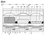
- 6A and 6B are sectional views showing a configuration example of a display device.
- FIG. 7A and 7B are cross-sectional views showing an example of a method for manufacturing a display device.
- 8A and 8B are cross-sectional views showing an example of a method for manufacturing a display device.
- FIG. 9 is a cross-sectional view showing a configuration example of the display device.
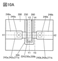
- FIG. 10A is a top view showing an example of a transistor.
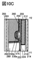
- 10B to 10D are cross-sectional views showing an example of a transistor.
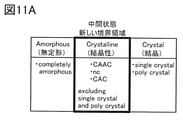
- FIG. 11A is a diagram illustrating the classification of the crystal structure of IGZO.
- FIG. 11B is a diagram illustrating an XRD spectrum of the CAAC-IGZO film.
- FIG. 11C is a diagram illustrating a microelectron diffraction pattern of the CAAC-IGZO film.
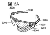
- FIG. 12A to 12D are views showing an example of an electronic device.
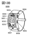
- 13A to 13F are views showing an example of an electronic device.
- FIG. 14 is a schematic diagram of the display device used in the simulation.
- FIG. 15 is a graph showing the light distribution characteristics of the light emitting element used in the simulation.
- FIG. 16 is a graph showing the simulation results.
- 17A and 17B are electron microscope images of the display device.
- FIG. 18 is a schematic diagram of the display device used in the simulation.
- FIG. 19 is a graph showing actual measurement results and simulation results of radiance in the display device according to this embodiment.
- an EL layer means a layer (also referred to as a light emitting layer) which is provided between a pair of electrodes of a light emitting element and contains at least a light emitting substance, or a laminated body containing a light emitting layer.
- FIG. 1A is a cross-sectional view showing a configuration example of a display device 10 which is a display device according to an aspect of the present invention.
- the display device 10 has a pixel 15R, a pixel 15G, and a pixel 15B.
- the pixels 15R, the pixels 15G, and the pixels 15B are provided on the display surface of the display device 10.
- the display surface can be configured such that the pixels 15R, the pixels 15G, and the pixels 15B are arranged in a matrix. It can be said that one pixel is composed of the pixel 15R, the pixel 15G, and the pixel 15B, and the pixels are arranged in a matrix on the display surface of the display device 10. In this case, it can be said that the pixel 15R, the pixel 15G, and the pixel 15B are sub-pixels, respectively.
- the display device 10 includes a substrate 11, a transistor 52, an insulating layer 13, a light emitting element 30, a partition wall 14, an insulating layer 63, an insulating layer 21, a colored layer 25R, a colored layer 25G, and a colored layer 25B. It has a flattening layer 27, a lens 29, a resin layer 33, and a substrate 12. One light emitting element 30 and one lens 29 are provided for each of the pixel 15R, the pixel 15G, and the pixel 15B. Further, the colored layer 25R is provided on the pixel 15R, the colored layer 25G is provided on the pixel 15G, and the colored layer 25B is provided on the pixel 15B.
- the light emitting element can be referred to as a light emitting device.
- the display element can be said to be a display device.
- the pixel 15G is adjacent to the pixel 15R and the pixel 15B.
- the light emitting elements 30 provided in the adjacent pixels, the colored layers, and the lenses 29 are adjacent to each other.
- the light emitting element 30 provided in the pixel 15R shown in FIG. 1A and the light emitting element 30 provided in the pixel 15G are adjacent to each other.
- the colored layer 25R and the colored layer 25G shown in FIG. 1A are adjacent to each other.
- the lens 29 provided in the pixel 15R shown in FIG. 1A and the lens 29 provided in the pixel 15G are adjacent to each other.
- the pixel 15R and the pixel 15B are not adjacent to each other in FIG. 1A, the pixel 15R and the pixel 15B may be adjacent to each other.
- the insulating layer 13 and the transistor 52 are provided on the substrate 11.
- the light emitting element 30 is provided on the insulating layer 13.
- the insulating layer 63 is provided on the light emitting element 30.
- the insulating layer 21 is provided on the insulating layer 63.
- the colored layer 25R, the colored layer 25G, and the colored layer 25B are provided on the insulating layer 21.
- the flattening layer 27 is provided on the colored layer 25R, the colored layer 25G, and the colored layer 25B.
- the lens 29 is provided on the flattening layer 27.
- the resin layer 33 is provided on the lens 29.
- the substrate 12 is provided on the resin layer 33.
- the upper surface of the insulating layer 13 is flattened, but it may not be flattened.
- an insulating substrate such as a glass substrate, a quartz substrate, a sapphire substrate, a ceramic substrate, a single crystal semiconductor substrate made of silicon or silicon carbide, a polycrystalline semiconductor substrate, a compound semiconductor substrate such as silicon germanium, etc.
- a semiconductor substrate such as an SOI substrate can be used.
- the display device 10 can be made a flexible display device.
- an organic insulating film is preferably used as the insulating layer 13 and the insulating layer 21, for example.
- the organic insulating film include acrylic resin, polyimide resin, epoxy resin, polyamide resin, polyimideamide resin, siloxane resin, benzocyclobutene resin, phenol resin, and precursors of these resins.
- an inorganic insulating film as the insulating layer 63.
- a silicon nitride film, a silicon nitride film, a silicon oxide film, a silicon nitride film, an aluminum oxide film, an aluminum nitride film, or the like can be used.
- two or more of the above-mentioned insulating films may be laminated and used.
- An inorganic insulating film may be used as the insulating layer 13 or the insulating layer 21, or an organic insulating film may be used as the insulating layer 63.
- the same material as the material that can be used as the insulating layer 13, the insulating layer 63, or the insulating layer 21 can be used.
- silicon oxynitride means that the content of oxygen is larger than the content of nitrogen as the composition thereof. Further, the silicon nitride oxide has a composition in which the nitrogen content is higher than the oxygen content.
- the colored layer 25R, the colored layer 25G, and the colored layer 25B are provided on different light emitting elements 30. Further, different lenses 29 are provided on the colored layer 25R, the colored layer 25G, and the colored layer 25B. From the above, the light emitting element 30, the colored layer 25R, and the lens 29 are provided so as to have regions that overlap each other. Further, the light emitting element 30, the colored layer 25G, and the lens 29 are provided so as to have a region overlapping with each other. Further, the light emitting element 30, the colored layer 25B, and the lens 29 are provided so as to have a region overlapping with each other.
- FIG. 1A a configuration having a region where two types of colored layers overlap is shown by a dotted line. Further, FIG. 1A shows a configuration in which the lenses 29 are provided apart from each other. The colored layers may not overlap each other, or may have a region where lenses 29 provided in adjacent pixels are in contact with each other.
- the light emitting element 30 has a structure in which a conductive layer 42, a light emitting layer 31, and a conductive layer 60 are laminated.
- the conductive layer 42 can be a pixel electrode of the light emitting element 30, and the conductive layer 60 can be a common electrode of the light emitting element 30.
- the light emitting element 30 can emit white light, for example. Specifically, white light can be emitted from the light emitting layer 31.
- an EL element such as an OLED (Organic Light Emitting Diode) or a QLED (Quantum-dot Light Emitting Diode) can be used. Further, a micro LED can be used as the light emitting element 30.
- the light emitting layer 31 contains two or more kinds of light emitting substances.
- white light emission can be obtained by selecting a light emitting substance so that the light emission of each of two or more light emitting substances has a complementary color relationship.
- a luminescent substance that emits light such as R (red), G (green), B (blue), Y (yellow), O (orange), or a spectral component of two or more colors of R, G, and B, respectively. It is preferable that two or more of the luminescent substances exhibiting luminescence containing the above-mentioned substances are contained.
- the emission spectrum of the material having a peak in the yellow wavelength region is preferably a material having a spectral component also in the green and red wavelength regions.
- the light emitting layer 31 preferably has a structure in which a light emitting layer containing a light emitting material that emits one color and a light emitting layer containing a light emitting material that emits another color are laminated.
- the plurality of light emitting layers in the light emitting layer 31 may be laminated so as to be in contact with each other, or may be laminated via a region that does not contain any of the light emitting materials.
- a region is provided between the fluorescent light emitting layer and the phosphorescent light emitting layer, which contains the same material as the fluorescent light emitting layer or the phosphorescent light emitting layer (for example, a host material or an assist material) and does not contain any light emitting material. May be good. This facilitates the fabrication of the light emitting element 30 and reduces the drive voltage.
- the plurality of light emitting layers 31 may be laminated via a charge generation layer.
- the conductive layer 42 can be electrically connected to the transistor 52 through an opening provided in the insulating layer 13 that reaches the transistor 52.
- the conductive layer 42 can be electrically connected to the source or drain of the transistor 52.
- the partition wall 14 has a function of electrically insulating (also referred to as electrically separating) the conductive layer 42 of different light emitting elements 30.
- the end portion of the conductive layer 42 is covered with the partition wall 14.
- an inorganic insulating film as the partition wall 14.
- a material similar to the material that can be used for the insulating layer 63 and the like can be used.
- An organic insulating film may be used as the partition wall 14.
- the partition wall 14 is a layer that transmits visible light. Instead of the partition wall 14, a partition wall that blocks visible light may be provided.
- the insulating layer 63 can be provided so as to cover the light emitting element 30.
- the insulating layer 63 is preferably made of a film that does not easily allow impurities such as water and hydrogen to permeate.
- the insulating layer 63 made of a film that does not easily allow impurities such as water or hydrogen to permeate so as to cover the light emitting element 30, it is possible to prevent impurities such as water or hydrogen from entering the light emitting element 30. Thereby, the reliability of the light emitting element 30 can be improved.
- the insulating layer 63 functions as a protective layer against the light emitting element 30.
- the insulating layer 63 may not be provided. In this case, it is preferable that the insulating layer 21 has a function as the above-mentioned protective layer.
- the insulating layer 21 can be provided on the light emitting element 30, and the colored layer 25R, the colored layer 25G, and the colored layer 25B can be provided on the insulating layer 21.
- the colored layer 25R, the colored layer 25G, and the colored layer 25B can be provided so as to be in contact with the upper surface of the insulating layer 21.
- the colored layer 25R, the colored layer 25G, and the colored layer 25B can be provided on the flat surface.
- the colored layer 25R has a function of transmitting, for example, red light.
- the colored layer 25G has a function of transmitting, for example, green light.
- the colored layer 25B has a function of transmitting, for example, blue light. In this case, red light is emitted from the pixel 15R, green light is emitted from the pixel 15G, and blue light is emitted from the pixel 15B.
- the colored layer 25R, the colored layer 25G, or the colored layer 25B may have a function of transmitting light such as cyan, magenta, and yellow. Further, although FIG. 1A shows three types of colored layers, the display device 10 may have four or more types of colored layers.
- a metal material As the colored layer 25R, the colored layer 25G, and the colored layer 25B, a metal material, a resin material, a resin material containing a pigment or a dye, or the like can be used.
- the pixels provided with the light emitting element 30 can be made fine.
- the colored layer 25R and the colored layer 25G can have regions that overlap each other.
- the colored layer 25G and the colored layer 25B can have regions that overlap each other.
- the colored layer 25R, the colored layer 25G, and the colored layer 25B are formed by, for example, photolithography and etching, even if the alignment accuracy of the mask used in the photolithography is low, the colored layer 25R, the colored layer 25G, and the colored layer 25B are colored.
- Layer 25B can be formed. Therefore, the pixel in which the light emitting element 30 is provided can be made fine.
- the thickness of the colored layer 25R, the thickness of the colored layer 25G, and the thickness of the colored layer 25B can be different from each other. Thereby, for example, the balance between the color purity of the light transmitted through the colored layer and the absorption rate of the light by the colored layer can be made desired for each color. Therefore, the display device 10 can display a high-quality image.
- the thickness of the colored layer 25R, the thickness of the colored layer 25G, and the thickness of the colored layer 25B may be the same as each other.
- the flattening layer 27 is provided on the colored layer 25R, the colored layer 25G, and the colored layer 25B.
- the flattening layer 27 can be provided so as to be in contact with the colored layer 25R, the colored layer 25G, and the colored layer 25B.
- the flattening layer 27 can be provided so as to be in contact with the upper surface and the side surface of the colored layer 25R, the colored layer 25G, and the colored layer 25B.
- the flattening layer 27 for example, a material similar to the material that can be used for the insulating layer 21 can be used.
- the lens 29 is provided on the flattening layer 27.
- the lens 29 can be a plano-convex lens having a flat portion 29a and a convex portion 29b.
- the lens 29 can be provided so that the flat portion 29a faces the substrate 11 side and the convex portion 29b faces the substrate 12 side.
- the lens 29 can be provided so that the flat portion 29a is in contact with the upper surface of the flattening layer 27.
- the thickness of the colored layer 25R, the thickness of the colored layer 25G, and the thickness of the colored layer 25B can be different from each other. Even in such a case, the flattening layer 27 is provided on the colored layer 25R, the colored layer 25G, and the colored layer 25B, and the lens 29 is provided on the flattening layer 27 to flatten each lens 29.
- the portions 29a can be provided on the same plane as each other. As a result, the distance L from the light emitting layer 31 of the light emitting element 30 to the flat portion 29a of the lens 29 can be made equal to each other.
- the distance to 29a can be equal to each other.
- the resin layer 33 is provided so as to be in contact with the convex portion 29b of the lens 29. Further, the substrate 12 is provided so as to be in contact with the upper surface of the resin layer 33. The resin layer 33 allows the lens 29 and the substrate 12 to be bonded together.
- an epoxy resin an acrylic resin, a silicone resin, a phenol resin, a polyimide resin, an imide resin, a PVC (polyvinyl chloride) resin, a PVB (polyvinyl butyral) resin, an EVA (ethylene vinyl acetate) resin and the like can be used.
- a two-component mixed type resin may be used.
- the refractive index of the resin layer 33 is lower than that of the lens 29.
- the lens 29 and the substrate 12 are bonded to each other by the resin layer 33, but one aspect of the present invention is not limited to this.
- they can be bonded by creating a vacuum between the lens 29 and the substrate 12.
- the resin layer 33 may not be provided.
- a substrate having translucency is used as the substrate 12.
- a glass substrate, a quartz substrate, a sapphire substrate, or the like can be used.
- the display device 10 can be made into a flexible display device.
- FIG. 1B is a diagram obtained by extracting from the alternate long and short dash line A1 to the alternate long and short dash line A2 from the cross-sectional view shown in FIG. 1A.
- the light emitted by the light emitting element 30 is shown as light 43.
- the term light may be paraphrased as a luminous flux.
- the light emitting element 30 emits light 43 not only in the front direction but also in the oblique direction. Assuming that the light 43 emitted in the diagonal direction is emitted from the pixels at the same angle, for example, when the user of the display device 10 looks at the display surface from the front of the display surface of the display device 10, it emits the light in the diagonal direction. The light 43 may not be visible to the user of the display device 10.
- the light emitted by the light emitting element 30 is incident on the flat portion 29a of the lens 29, if the refractive index of the resin layer 33 is lower than the refractive index of the lens 29 as described above, according to Snell's law, FIG. 1B shows.
- the light emitted in the diagonal direction can be focused in the front direction.
- the amount of light of the light 43 visually recognized by the user of the display device 10 can be increased. Therefore, the user of the display device 10 can visually recognize a bright image.
- the display device 10 can be a display device having low power consumption and can be a highly reliable display device.
- the refractive index of the lens 29 can be, for example, 1.5 or more and 1.8 or less, for example, 1.5 or more and 1.6 or less, for example, 1.56. Further, the refractive index of the resin layer 33 can be, for example, 1.2 or more and 1.5 or less, for example, 1.3 or more and less than 1.5, and can be, for example, 1.40. When the resin layer 33 is not provided and the lens 29 and the substrate 12 are bonded by creating a vacuum, the refractive index of the lens 29 may be larger than 1.
- R1 represents the radius of curvature of the convex portion 29b
- N1 represents the refractive index of the lens
- N2 represents the refractive index of the resin layer 33
- N3 represents the refractive index of the flattening layer 27.
- the focal length of the lens 29 is "R1 x N3 / (N1-N2)".
- the thickness of the colored layer 25R, the thickness of the colored layer 25G, and the thickness of the colored layer 25B can be different from each other. Therefore, if the lens 29 is provided on the colored layer 25R, the colored layer 25G, and the colored layer 25B without providing the flattening layer 27, the distance L differs for each pixel. If the distance L is different for each pixel, it may be necessary to change the radius of curvature R1 of the convex portion 29b or the refractive index N1 of the lens 29 for each pixel according to the equation (1). In this case, the lens 29 is manufactured separately for each pixel, which complicates the manufacturing process of the display device.
- the display device 10 since the lens 29 is provided on the flattening layer 27, the distance L can be made equal for each pixel. Therefore, the display device 10 can simplify the manufacturing process. Therefore, the manufacturing cost of the display device 10 can be reduced, and the display device 10 can be made inexpensive.
- FIG. 2A is a modified example of the display device 10 shown in FIG. 1A.
- a light emitting layer 51 is provided in place of the light emitting layer 31, and a wavelength conversion layer 55R and a wavelength conversion layer 55G are provided in place of the colored layer 25R, the colored layer 25G, and the colored layer 25B.
- the point is different from the display device 10 shown in FIG. 1A.
- the light emitting layer 51 has a function of emitting, for example, blue light.
- the wavelength conversion layer 55R provided on the pixel 15R has a function of converting the light emitted by the light emitting layer 51 into red light.
- the wavelength conversion layer 55G provided in the pixel 15G has a function of converting the light emitted by the light emitting layer 51 into green light.
- the pixel 15B does not need to be provided with a wavelength conversion layer.
- the light emitting layer 51 may have a function of emitting ultraviolet light. In this case, by providing the pixel 15B with a wavelength conversion layer having a function of converting the light emitted by the light emitting layer 51 into blue light, the pixel 15B can emit blue light.
- the wavelength conversion layer 55R and the wavelength conversion layer 55G include a fluorescent material or a quantum dot (QD: Quantum dot).
- QD Quantum dot
- quantum dots have a narrow peak width in the emission spectrum, high conversion efficiency, and can obtain emission with high color purity. As a result, the color reproducibility of the display device 10 can be made high, so that the display device 10 can display a high-quality image.
- a phosphor or quantum dots may be dispersed in an organic resin.
- the organic resin a curable material having transparency to the light emitted by the light emitting layer 51 and the light emitted by the wavelength conversion layer 55R or the wavelength conversion layer 55G can be used.
- the wavelength conversion layer 55R and the wavelength conversion layer 55G can be formed by using, for example, a droplet ejection method (for example, an inkjet method), a coating method, an imprint method, various printing methods (screen printing, offset printing), and the like. Further, by using a photosensitive resin material as the organic resin, it may be formed by applying the organic resin by a spin coating method or the like and then processing it into an arbitrary shape through an exposure treatment and a development treatment.
- a droplet ejection method for example, an inkjet method
- a coating method for example, an imprint method
- various printing methods screen printing, offset printing
- a photosensitive resin material as the organic resin
- it may be formed by applying the organic resin by a spin coating method or the like and then processing it into an arbitrary shape through an exposure treatment and a development treatment.
- the material constituting the quantum dot is not particularly limited, and belongs to, for example, a group 14 element, a group 15 element, a group 16 element, a compound composed of a plurality of group 14 elements, and groups 4 to 14.
- cadmium selenium, cadmium sulfide, cadmium tellurized zinc selenium, zinc oxide, zinc sulfide, zinc telluride, mercury sulfide, mercury sulphide, mercury telluride, indium arsenide, indium phosphate, gallium arsenide.
- quantum dots examples include a core type, a core-shell type, and a core-multishell type.
- a protective agent is attached or a protecting group is provided on the surface of the quantum dot. By the attachment of the protective agent or the provision of a protecting group, aggregation can be prevented and the solubility in a solvent can be enhanced. It is also possible to reduce reactivity and improve electrical stability.
- the size of the quantum dots is appropriately adjusted so that light having a desired wavelength can be obtained.
- the emission of the quantum dots shifts to the blue side, that is, to the high energy side. Therefore, by changing the size of the quantum dots, the wavelengths of the spectra in the ultraviolet region, visible region, and infrared region are used. Its emission wavelength can be adjusted over the region.
- the size (diameter) of the quantum dots is, for example, 0.5 nm or more and 20 nm or less, preferably 1 nm or more and 10 nm or less.
- the narrower the size distribution of the quantum dots the narrower the emission spectrum becomes, and the better the color purity of the quantum dots can be obtained.
- the shape of the quantum dot is not limited to a spherical shape, and may be a rod shape, a disk shape, or another shape.
- the directivity of the light emitted by the wavelength conversion layer 55R and the light emitted by the wavelength conversion layer 55G is low.
- the flat portion 29a of the lens 29 faces the wavelength conversion layer 55R and the wavelength conversion layer 55G side, and the convex portion 29b faces the substrate 12 side.
- the refractive index of the resin layer 33 is lower than the refractive index of the lens 29. From the above, even when the directivity of the light emitted by the wavelength conversion layer 55R and the light emitted by the wavelength conversion layer 55G is low, the light can be focused in the front direction by the lens 29.
- the display device 10 can be a display device having low power consumption and can be a highly reliable display device.
- the pixel 15R and the pixel 15G are provided with a wavelength conversion layer, but the pixel 15B is not provided with a wavelength conversion layer.
- the flattening layer 27 and providing the lens 29 on the flattening layer 27 are the same. It can be provided on a flat surface.
- the distance L from the light emitting layer of the light emitting element 30 to the flat portion 29a of the lens 29 can be made equal to each other, and the manufacturing process of the display device 10 can be simplified.
- FIG. 2B is a modified example of the display device 10 shown in FIG. 2A.
- the display device 10 shown in FIG. 2B is different from the display device 10 shown in FIG. 2A in that the colored layer 25R and the colored layer 25G are provided.
- the colored layer 25R is provided on the wavelength conversion layer 55R.
- the colored layer 25G is provided on the wavelength conversion layer 55G.
- Some of the light incident on the wavelength conversion layer 55R or the wavelength conversion layer 55G from the light emitting layer 51 may not be wavelength-converted.
- the light emitting layer 51 emits blue light
- the red light emitted by the wavelength conversion layer 55R or the green light emitted by the wavelength conversion layer 55G and the blue light emitted by the light emitting layer 51 are mixed. Color purity may decrease. Therefore, by arranging the colored layer 25R and the colored layer 25G on the substrate 12 side of the wavelength conversion layer 55R or the wavelength conversion layer 55G, respectively, the blue light transmitted through the wavelength conversion layer 55R or the wavelength conversion layer 55G can be generated. It is possible to suppress the emission to the outside of the display device 10. As a result, the decrease in color purity of the light emitted from the pixel 15R and the light emitted from the pixel 15G is suppressed, and the display device 10 can display a high-quality image.
- FIG. 3 is a cross-sectional view showing another configuration example of the display device 10.
- the display device 10 shown in FIG. 3 is different from the display device 10 shown in FIG. 1A in the structure of the layer above the insulating layer 21.
- a lens 29 is provided on the insulating layer 21.
- the flat portion 29a of the lens 29 can be provided so as to be in contact with the upper surface of the insulating layer 21.
- the resin layer 33 is provided so as to be in contact with the convex portion 29b of the lens 29.
- the refractive index of the resin layer 33 is preferably lower than that of the lens 29.
- a colored layer 25R, a colored layer 25G, and a colored layer 25B are provided on the resin layer 33.
- the adhesive layer 37 is provided on the colored layer 25R, the colored layer 25G, and the colored layer 25B.
- various curable adhesives such as a photocurable adhesive such as an ultraviolet curable adhesive, a reaction curable adhesive, a heat curable adhesive, and an anaerobic adhesive can be used, for example, on the resin layer 33.
- a photocurable adhesive such as an ultraviolet curable adhesive, a reaction curable adhesive, a heat curable adhesive, and an anaerobic adhesive can be used, for example, on the resin layer 33.
- the same materials as those that can be used can be used.
- the substrate 12 is provided on the adhesive layer 37.
- the adhesive layer 37 allows the colored layer 25R, the colored layer 25G, the colored layer 25B, and the substrate 12 to be bonded together.
- the lens 29 is provided between the light emitting element 30 and the colored layer 25R, the colored layer 25G, and the colored layer 25B.
- the distance L from the light emitting layer 31 of the light emitting element 30 to the flat portion 29a of the lens 29 can be made shorter than that of the display device 10 shown in FIG. 1A or the like. Therefore, as can be seen from the equation (1), the radius of curvature R1 of the convex portion 29b can be reduced. Further, the refractive index N1 of the lens 29 can be increased. Further, the refractive index N2 of the resin layer 33 can be reduced. Further, the refractive index N3 of the flattening layer 27 can be reduced.
- FIG. 4A is a cross-sectional view showing another configuration example of the display device 10.
- the display device 10 shown in FIG. 4A is different from the display device 10 shown in FIG. 1A in that it has a partition wall 35.
- the partition wall 35 can be provided at the boundary of pixels.
- the partition wall 35 can be provided straddling the pixels 15R and the pixels 15G. Further, the partition wall 35 can be provided straddling the pixels 15G and the pixels 15B.
- the partition wall 35 is provided on the insulating layer 21.
- the partition wall 35 can be provided so as to be in contact with the upper surface of the insulating layer 21.
- the shape of the partition wall 35 can be, for example, a hexahedron.
- the colored layer 25R, the colored layer 25G, and the colored layer 25B can be provided so as to be in contact with the side surface of the partition wall 35.
- the coloring layer 25G may be in contact with the facing surface of the side surface of the partition wall 35 in contact with the coloring layer 25R.
- the coloring layer 25B may be in contact with the facing surface of the side surface of the partition wall 35 in contact with the coloring layer 25G.
- the refractive index of the partition wall 35 is lower than the refractive index of the colored layer 25R, the colored layer 25G, and the colored layer 25B.
- a partition wall 35 it is preferable to use, for example, a polymer containing fluorine.
- an organic insulating film such as an acrylic resin, a polyimide resin, an epoxy resin, a polyamide resin, a polyimide amide resin, a siloxane resin, a benzocyclobutene resin, a phenol resin, and a precursor of these resins can be used. ..
- An inorganic insulating film may be used as the partition wall 35.
- FIG. 4B is a diagram obtained by extracting from the alternate long and short dash line A3 to the alternate long and short dash line A4 from the cross-sectional view shown in FIG. 4A.
- the light emitted by the light emitting element 30 and radiated to the partition wall 35 is shown as light 47.
- the display device 10 shown in FIG. 4A can be a display device having high light extraction efficiency. Therefore, the display device 10 shown in FIG. 4A allows the user of the display device 10 to visually recognize a bright image. Further, the display device 10 shown in FIG. 4A can be a display device having low power consumption and can be a display device having high reliability.
- the display device 10 shown in FIG. 4A since the light 47 can be suppressed from being incident on, for example, the colored layer provided in the adjacent pixel, the color purity can be improved. Therefore, the display device 10 can display a high-quality image.
- the display device 10 shown in FIG. 4A can be a display device having high light extraction efficiency. If the absorption of the light 47 by the partition wall 35 is within the allowable range, a reflective material such as metal may be used as the partition wall 35.
- the angle of the taper of the partition wall 35 so that the light 47 can be totally reflected and the light 47 totally reflected can be suppressed from being incident on the adjacent pixel.
- the taper angle is small, that is, the side surface of the partition wall 35 is close to vertical
- the light 47 totally reflected by the side surface of the partition wall 35 may be incident on the adjacent pixel.
- the light 47 totally reflected by the partition wall 35 may be incident on the lens 29 provided in the adjacent pixel.
- the taper angle is large, that is, when the side surface of the partition wall 35 is close to horizontal, the incident angle of the light 47 at the interface between the partition wall 35 and the colored layer becomes small, and total reflection of the light 47 may not occur.
- the thickness of the partition wall 35 is equal to that of the colored layer 25B, but one aspect of the present invention is not limited to this.
- the thickness of the partition wall 35 may be thinner or thicker than the thickness of the colored layer 25B. Further, the thickness of the partition wall 35 may be thinner or thicker than the thickness of the colored layer 25G. Further, the thickness of the partition wall 35 may be thinner or thicker than the thickness of the colored layer 25R.
- FIG. 5A is a modified example of the display device 10 shown in FIG. 4A.
- the display device 10 shown in FIG. 5A is different from the display device 10 shown in FIG. 4A in that a light-shielding layer 45 is provided.
- the light-shielding layer 45 can be provided between the layer on which the light emitting element 30 is provided and the layer on which the partition wall 35 is provided.
- FIG. 5A shows an example in which the light-shielding layer 45 is provided so as to be in contact with the upper surface of the insulating layer 21, and the partition wall 35 is provided so as to be in contact with the upper surface of the light-shielding layer 45.
- FIG. 5B is a diagram obtained by extracting from the alternate long and short dash line A5 to the alternate long and short dash line A6 from the cross-sectional view shown in FIG. 5A.
- the light emitted by the light emitting element 30 and radiated to the bottom surface of the light shielding layer 45 is shown as light 49.
- the light 49 irradiates the bottom surface of the partition wall 35.
- the refractive index of the partition wall 35 is lower than the refractive index of the insulating layer 21, the light 49 may be totally reflected at the interface between the bottom surface of the partition wall 35 and the upper surface of the insulating layer 21. As a result, stray light of the light 49 may be generated, and the light 49 may leak to the adjacent pixel.
- the light-shielding layer 45 can absorb the light 49. Therefore, it is possible to prevent the light 49 from leaking to the adjacent pixels. Therefore, for example, it is possible to suppress the light 49 from entering the colored layer provided in the adjacent pixel, so that the color purity can be improved. Therefore, the display device 10 can display a high-quality image.
- the partition wall 35 is configured to cover the side surface of the light-shielding layer 45.
- the partition wall 35 may not cover the side surface of the light-shielding layer 45, and the side surface of the light-shielding layer 45 may be in contact with the colored layer.
- carbon black As the light-shielding layer 45, carbon black, a metal oxide, a composite oxide containing a solid solution of a plurality of metal oxides, or the like can be used.
- FIG. 6A is a cross-sectional view showing another configuration example of the display device 10.
- the display device 10 shown in FIG. 6A is different from the display device 10 shown in FIG. 1A in that the colored layer 25R, the colored layer 25G, and the colored layer 25B are provided so as to be separated from each other. Further, it is different from the display device 10 shown in FIG. 1A in that the flattening layer 57 is provided instead of the flattening layer 27.
- the refractive index of the flattening layer 57 is lower than the refractive index of the colored layer 25R, the colored layer 25G, and the colored layer 25B.
- the display device 10 shown in FIG. 6A can be a display device that allows the user of the display device 10 to visually recognize a bright image, similar to the display device 10 shown in FIG. 4A.
- the display device 10 shown in FIG. 6A can be a display device having low power consumption and can be a display device having high reliability.
- the flattening layer 57 a material similar to the material that can be used for the resin layer 33 can be used. Further, as the flattening layer 57, the same material as the material that can be used for the partition wall 35 can be used.
- the display device 10 shown in FIG. 6A can obtain the same effect as the case where the partition wall 35 is provided, even though the partition wall 35 is not provided. Therefore, the display device 10 shown in FIG. 6A can simplify the manufacturing process because the partition wall 35 is not provided. Therefore, the manufacturing cost of the display device 10 can be reduced, and the display device 10 can be made inexpensive.
- FIG. 6B is a modified example of the display device 10 shown in FIG. 6A.
- the display device 10 shown in FIG. 6B is different from the display device 10 shown in FIG. 6A in that the light-shielding layer 45 is provided.
- the display device 10 is configured such that the colored layers do not overlap with each other, a part of the light emitted by the light emitting element 30 may leak to the adjacent pixels, and the leaked light may be incident on the colored layer provided in the adjacent pixels.
- a part of the light emitted by the light emitting element 30 provided in the pixel 15G may be incident on the colored layer 25R or the colored layer 25B.
- the light-shielding layer 45 as shown in FIG. 6B, the light leakage can be suppressed, so that the color purity can be improved. Therefore, the display device 10 can display a high-quality image.
- the light-shielding layer 45 is provided apart from the colored layer 25R, the colored layer 25G, and the colored layer 25B.
- the light incident on the colored layer 25R, the colored layer 25G, or the colored layer 25B is shielded from light as compared with the case where the light-shielding layer 45 overlaps the colored layer 25R, the colored layer 25G, or a part of the colored layer 25B.
- the proportion of light incident on the layer 45 can be reduced.
- the light-shielding layer 45 may overlap with the colored layer 25R, the colored layer 25G, or a part of the colored layer 25B.
- the configurations shown in the present specification can be implemented in appropriate combinations.
- the configuration shown in FIG. 2A or FIG. 2B and the configuration shown in FIGS. 3, 4A, 5A, 6A, or 6B can be implemented in combination.
- the wavelength conversion layer 55R and the wavelength conversion layer 55G can be provided.
- the thin films (insulating film, semiconductor film, conductive film, colored film, etc.) constituting the display device include a sputtering method, a chemical vapor deposition (CVD) method, a vacuum vapor deposition method, and a pulse laser deposition (PLD:). It can be formed by using a Pulsed Laser Deposition) method, an atomic layer deposition (ALD) method, or the like.
- the CVD method may be a plasma chemical vapor deposition (PECVD) method or a thermal CVD method.
- PECVD plasma chemical vapor deposition
- MOCVD organometallic chemical vapor deposition
- the thin film constituting the display device can be formed by a method such as spin coating, dip, spray coating, inkjet, dispense, screen printing, offset printing, doctor knife, slit coating, roll coating, curtain coating, knife coating and the like.
- a thin film constituting a display device When processing a thin film constituting a display device, it can be processed by using a lithography method or the like. Alternatively, an island-shaped thin film may be formed by a film forming method using a shielding mask. Alternatively, the thin film may be processed by a nanoimprint method, a sandblast method, a lift-off method, or the like.
- a photolithography method for example, there are the following two methods. One is to apply a photosensitive resist material on the thin film to be processed, expose it through a photomask, develop it to form a resist mask, and process the thin film by etching or the like to obtain a resist mask. It is a method of removing. The other is a method in which a photosensitive thin film is formed, and then exposed and developed to process the thin film into a desired shape.
- i-line wavelength 365 nm
- g-line wavelength 436 nm
- h-line wavelength 405 nm
- the exposure may be performed by the immersion exposure technique.
- extreme ultraviolet EUV: Extreme Ultra-violet
- X-rays an electron beam can be used instead of the light used for exposure. It is preferable to use extreme ultraviolet light, X-rays, or an electron beam because extremely fine processing is possible.
- extreme ultraviolet light, X-rays, or an electron beam because extremely fine processing is possible.
- a dry etching method, a wet etching method, a sandblasting method, or the like can be used for etching the thin film.
- the transistor 52 is formed on the substrate 11.
- the insulating layer 13 is formed on the substrate 11 and the transistor 52.
- an opening reaching the transistor 52 is formed in the insulating layer 13.
- a conductive film to be a conductive layer 42 is formed on the insulating layer 13, and a part of the conductive film is etched to form the conductive layer 42.
- the partition wall 14 is formed so as to cover the end portion of the conductive layer 42.
- the light emitting layer 31 and the conductive layer 60 are formed.
- the light emitting layer 31 can be formed by a method such as a thin film deposition method, a coating method, a printing method, or a ejection method.
- a vapor deposition method that does not use a metal mask can be used.
- the conductive layer 60 can be formed by a method such as a thin film deposition method or a sputtering method.
- the insulating layer 63 is formed on the conductive layer 60.
- the light emitting element 30 is sealed by the insulating layer 63.
- the insulating layer 21 is formed on the insulating layer 63.
- an organic insulating film is formed by a spin coating method or the like.
- the insulating layer 21 can be made into a flattening layer. The upper surface of the insulating layer 21 may not be flattened.
- the colored layer 25R, the colored layer 25G, and the colored layer 25B are formed on the insulating layer 21 (FIG. 7B).
- a colored film to be a colored layer 25B is first formed, and the colored film is processed by, for example, a lithography method, for example, a photolithography method to form the colored layer 25B.
- a colored film to be a colored layer 25G is formed, and the colored film is processed by, for example, a lithography method, for example, a photolithography method to form the colored layer 25G.
- a colored film to be the colored layer 25R is formed, and the colored film is processed by, for example, a lithography method, for example, a photolithography method to form the colored layer 25R.
- a film to be a partition wall 35 is formed after the insulating layer 21 is formed, and a part of the film is etched to form the partition wall 35. After that, the colored layer 25B, the colored layer 25G, and the colored layer 25R are formed. Further, when the display device 10 shown in FIG. 5A is manufactured, a film to be a light-shielding layer 45 is formed, a part of the film is etched to form a light-shielding layer 45, and then a film to be a partition wall 35 is formed. A partition wall 35 is formed by forming a film and etching a part of the film.
- a film to be a flattening layer 27 is formed on the colored layer 25R, the colored layer 25G, and the colored layer 25B.
- an organic insulating film is formed by a spin coating method or the like (FIG. 8A).
- the lens 29 is formed on the flattening layer 27 (FIG. 8B).
- the lens 29 can be formed by, for example, forming a resist pattern by a lithography method and then heating the substrate 11 to reflow the resist.
- the substrate 12 is prepared, and the resin layer 33 is formed on the substrate 12.
- the resin layer 33 can be formed by a screen printing method, a dispensing method, or the like.
- the lens 29 and the substrate 12 are bonded together by the resin layer 33. From the above, the display device 10 shown in FIG. 1B can be manufactured.
- FIG. 9 is a cross-sectional view showing a configuration example of the display device 10.
- FIG. 9 shows a more specific configuration example of the display device 10 shown in FIG.
- the insulating layer 152, the transistor 52, the insulating layer 162, the insulating layer 181 and the insulating layer 182, the insulating layer 183, the insulating layer 185, the conductive layer 189a, the conductive layer 189b, and the conductive layer are placed on the substrate 11.
- 189c, a conductive layer 189d, an insulating layer 186, and an insulating layer 187 are provided.
- the light emitting element 30 has a conductive layer 42, a light emitting layer 31, and a conductive layer 60.
- the transistor 52 has a conductive layer 161, an insulating layer 163, an insulating layer 164, a metal oxide layer 165, a pair of conductive layers 166, an insulating layer 167, a conductive layer 168, and the like. Specific examples of transistors that can be used in the display device of one aspect of the present invention, such as the transistor 52, will be described in detail in the second embodiment.
- the metal oxide layer 165 has a channel forming region.
- the metal oxide layer 165 has a first region that overlaps with one of the pair of conductive layers 166, a second region that overlaps with the other of the pair of conductive layers 166, and between the first region and the second region. It has a third region of.
- a conductive layer 161 and an insulating layer 162 are provided on the insulating layer 152, and an insulating layer 163 and an insulating layer 164 are provided so as to cover the conductive layer 161 and the insulating layer 162.
- the metal oxide layer 165 is provided on the insulating layer 164.
- the conductive layer 161 functions as a gate electrode, and the insulating layer 163 and the insulating layer 164 function as a gate insulating layer.
- the conductive layer 161 overlaps with the metal oxide layer 165 via the insulating layer 163 and the insulating layer 164.
- the insulating layer 163 preferably functions as a barrier layer like the insulating layer 152. It is preferable to use an oxide insulating film such as a silicon oxide film for the insulating layer 164 in contact with the metal oxide layer 165.
- the height of the upper surface of the conductive layer 161 substantially coincides with the height of the upper surface of the insulating layer 162. As a result, the size of the transistor 52 can be reduced.
- the pair of conductive layers 166 are provided apart on the metal oxide layer 165.
- the pair of conductive layers 166 functions as a source and a drain.
- An insulating layer 181 is provided so as to cover the metal oxide layer 165 and the pair of conductive layers 166, and an insulating layer 182 is provided on the insulating layer 181.
- the insulating layer 181 and the insulating layer 182 are provided with an opening reaching the metal oxide layer 165, and the insulating layer 167 and the conductive layer 168 are embedded in the openings. The opening overlaps with the third region.
- the insulating layer 167 overlaps the side surface of the insulating layer 181 and the side surface of the insulating layer 182.
- the conductive layer 168 overlaps the side surface of the insulating layer 181 and the side surface of the insulating layer 182 via the insulating layer 167.
- the conductive layer 168 functions as a gate electrode, and the insulating layer 167 functions as a gate insulating layer.
- the conductive layer 168 overlaps with the metal oxide layer 165 via the insulating layer 167.
- the height of the upper surface of the conductive layer 168 substantially coincides with the height of the upper surface of the insulating layer 182. As a result, the size of the transistor 52 can be reduced.
- An insulating layer 183 and an insulating layer 185 are provided so as to cover the upper surfaces of the insulating layer 182, the insulating layer 167, and the conductive layer 168.
- the insulating layer 152, the insulating layer 181 and the insulating layer 183 suppress the invasion of impurities such as water or hydrogen into the metal oxide layer 165 and the desorption of oxygen from the metal oxide layer 165. It has a function as a barrier layer. Further, by covering the pair of conductive layers 166 with the insulating layer 181, it is possible to suppress the oxidation of the pair of conductive layers 166 by the oxygen contained in the insulating layer 182.
- the insulating layer 152, the insulating layer 181 and the insulating layer 183 for example, a film such as an aluminum oxide film, a hafnium oxide film, or a silicon nitride film, which is less likely to diffuse hydrogen and oxygen than a silicon oxide film, can be used.
- One of the pair of conductive layers 166 and a plug electrically connected to the conductive layer 189a are embedded in openings provided in the insulating layer 181, the insulating layer 182, the insulating layer 183, and the insulating layer 185.
- the plug preferably has a conductive layer 184b in contact with the side surface of the opening and one upper surface of the pair of conductive layers 166, and a conductive layer 184a embedded inside the conductive layer 184b. At this time, it is preferable to use a conductive material as the conductive layer 184b, which is difficult for hydrogen and oxygen to diffuse.
- a conductive layer 189a and an insulating layer 186 are provided on the insulating layer 185, a conductive layer 189b is provided on the conductive layer 189a, and an insulating layer 187 is provided on the insulating layer 186.
- the insulating layer 186 preferably has a flattening function.
- the height of the upper surface of the conductive layer 189b substantially coincides with the height of the upper surface of the insulating layer 187.
- the insulating layer 187 and the insulating layer 186 are provided with an opening reaching the conductive layer 189a, and the conductive layer 189b is embedded inside the opening.
- the conductive layer 189b functions as a plug for electrically connecting the conductive layer 189a and the conductive layer 42.
- One of the pair of conductive layers 166 of the transistor 52 is electrically connected to the conductive layer 42 of the light emitting element 30 via the conductive layer 184a, the conductive layer 184b, the conductive layer 189a, and the conductive layer 189b.
- the insulating layer 186 is preferably formed by using an inorganic insulating material such as silicon oxide, silicon nitride nitride, silicon nitride, silicon nitride, aluminum oxide, hafnium oxide, and titanium nitride.
- an inorganic insulating material such as silicon oxide, silicon nitride nitride, silicon nitride, silicon nitride, aluminum oxide, hafnium oxide, and titanium nitride.
- the insulating layer 187 for example, a film such as an aluminum oxide film, a hafnium oxide film, or a silicon nitride film, which is less likely to diffuse hydrogen and oxygen than a silicon oxide film, can be used.
- the insulating layer 187 preferably has a function as a barrier layer that prevents impurities such as water and hydrogen from entering the transistor 52.
- the conductive layer 189c is electrically connected to the FPC via the conductive layer 189d, the conductive layer 190, and the conductive layer 195. A signal and electric power are supplied to the display device 10 via the FPC.
- the conductive layer 189c can be formed by the same material and the same process as the conductive layer 189a.
- the conductive layer 189d can be formed by the same material and the same process as the conductive layer 189b.
- the conductive layer 190 can be formed by the same material and the same process as the conductive layer 42.
- an anisotropic conductive film (ACF: Anisotropic Conducive Film), an anisotropic conductive paste (ACP: Anisotropic Conducive Paste), or the like can be used.
- ACF Anisotropic Conducive Film
- ACP Anisotropic Conducive Paste
- This embodiment can be carried out in combination with other embodiments described in the present specification, or examples thereof, at least in part thereof.
- the structure of the transistor included in the display device is not particularly limited. For example, it may be a planar type transistor, a stagger type transistor, or an inverted stagger type transistor. Further, either a transistor structure having a top gate structure or a bottom gate structure may be used. Alternatively, gate electrodes may be provided above and below the channel.
- the transistor included in the display device for example, a transistor using a metal oxide in the channel forming region can be used. This makes it possible to realize a transistor having an extremely small off-current.
- a transistor having silicon in the channel forming region may be applied to the transistor included in the display device.
- the transistor include a transistor having amorphous silicon, a transistor having crystalline silicon (typically, low-temperature polysilicon), a transistor having single crystal silicon, and the like.
- a transistor using a metal oxide in the channel forming region and a transistor having silicon in the channel forming region may be used in combination.
- the transistor is an element having at least three terminals including a gate, a drain, and a source. Further, it has a region (hereinafter, also referred to as a channel forming region) in which a channel is formed between the drain (drain terminal, drain region, or drain electrode) and the source (source terminal, source region, or source electrode). , A current can flow between the source and the drain through the channel formation region.
- the channel forming region means a region in which a current mainly flows.
- the functions of the source and the drain may be interchanged when transistors having different polarities are adopted or when the direction of the current changes in the circuit operation. Therefore, in the present specification and the like, the terms source and drain may be used interchangeably.
- the channel length is, for example, a source in a region where a semiconductor (or a portion where a current flows in a semiconductor when the transistor is on) and a gate electrode overlap each other in a top view of a transistor, or a channel formation region.
- the channel length does not always take the same value in all regions. That is, the channel length of one transistor may not be fixed to one value. Therefore, in the present specification, the channel length is any one value, the maximum value, the minimum value, or the average value in the channel formation region.
- the channel width is, for example, the channel length direction in the region where the semiconductor (or the portion where the current flows in the semiconductor when the transistor is on) and the gate electrode overlap each other in the top view of the transistor, or in the channel formation region. Refers to the length of the channel formation region in the vertical direction with respect to. In one transistor, the channel width does not always take the same value in all regions. That is, the channel width of one transistor may not be fixed to one value. Therefore, in the present specification, the channel width is any one value, the maximum value, the minimum value, or the average value in the channel formation region.
- the channel width in the region where the channel is actually formed (hereinafter, also referred to as “effective channel width”) and the channel width shown in the top view of the transistor (hereinafter, also referred to as “effective channel width”).
- effective channel width when the gate electrode covers the side surface of the semiconductor, the effective channel width may be larger than the apparent channel width, and the influence thereof may not be negligible.
- the ratio of the channel forming region formed on the side surface of the semiconductor may be large. In that case, the effective channel width is larger than the apparent channel width.
- channel width may refer to an apparent channel width.
- channel width may refer to an effective channel width.
- the values of the channel length, channel width, effective channel width, apparent channel width, etc. can be determined by analyzing a cross-sectional TEM image or the like.
- the term “insulator” can be paraphrased as an insulating film or an insulating layer.
- the term “conductor” can be paraphrased as a conductive film or a conductive layer.
- the term “oxide” can be paraphrased as an oxide film or an oxide layer.
- the term “semiconductor” can be paraphrased as a semiconductor film or a semiconductor layer.
- FIG. 10A shows a top view of the transistor 200.
- FIG. 10B shows a cross-sectional view between the alternate long and short dash lines X1-X2 in FIG. 10A.
- FIG. 10B can be said to be a cross-sectional view of the transistor 200 in the channel length direction.
- FIG. 10C shows a cross-sectional view between the alternate long and short dash lines Y1-Y2 in FIG. 10A.
- FIG. 10C can be said to be a cross-sectional view of the transistor 200 in the channel width direction.
- FIG. 10D shows a cross-sectional view between the alternate long and short dash lines Y3-Y4 in FIG. 10A.
- the semiconductor devices shown in FIGS. 10A to 10D include an insulator 212 on a substrate (not shown), an insulator 214 on the insulator 212, a transistor 200 on the insulator 214, and an insulator 280 on the transistor 200. It has an insulator 282 on the insulator 280, an insulator 283 on the insulator 282, and an insulator 285 on the insulator 283.
- the insulator 212, the insulator 214, the insulator 280, the insulator 282, the insulator 283, and the insulator 285 function as an interlayer insulating film.
- conductor 240 (conductor 240a and conductor 240b) that is electrically connected to the transistor 200 and functions as a plug.
- Insulators 241 (insulators 241a and insulators 241b) are provided in contact with the side surfaces of the conductor 240 that functions as a plug.
- conductors 246 (conductors 246a and 246b) that are electrically connected to the conductor 240 and function as wiring are provided.
- the insulator 241a is provided in contact with the inner wall of the opening of the insulator 280, the insulator 282, the insulator 283, and the insulator 285, and the first conductor of the conductor 240a is provided in contact with the side surface of the insulator 241a. Further, a second conductor of the conductor 240a is provided inside. Further, the insulator 241b is provided in contact with the inner wall of the opening of the insulator 280, the insulator 282, the insulator 283, and the insulator 285, and the first conductor of the conductor 240b is in contact with the side surface of the insulator 241b. A second conductor of the conductor 240b is provided inside.
- the height of the upper surface of the conductor 240 and the height of the upper surface of the insulator 285 in the region overlapping with the conductor 246 can be made about the same.
- the conductor 240 may be provided as a single layer or a laminated structure having three or more layers. When the structure has a laminated structure, an ordinal number may be given in the order of formation to distinguish them.
- the transistor 200 includes an insulator 216 on the insulator 214 and a conductor 205 (conductor 205a, conductor 205b, and a conductor) arranged so as to be embedded in the insulator 216. 205c), the insulator 222 on the insulator 216 and the conductor 205, the insulator 224 on the insulator 222, the oxide 230a on the insulator 224, and the oxide 230b on the oxide 230a.
- a conductor 205 conductor 205a, conductor 205b, and a conductor
- the oxide 243 (oxide 243a and oxide 243b) on the oxide 230b, the conductor 242a on the oxide 243a, the insulator 271a on the conductor 242a, the conductor 242b on the oxide 243b, and the conductivity.
- insulator 275 which is arranged in the same manner.
- the oxide 230a and the oxide 230b may be collectively referred to as an oxide 230.
- the conductor 242a and the conductor 242b may be collectively referred to as a conductor 242.
- the insulator 271a and the insulator 271b may be collectively referred to as an insulator 271.
- the insulator 280 and the insulator 275 are provided with an opening reaching the oxide 230b.
- An insulator 250 and a conductor 260 are arranged in the opening. Further, in the channel length direction of the transistor 200, the insulator 260 and the insulator 250 are provided between the insulator 271a, the conductor 242a, and the oxide 243a, and the insulator 271b, the conductor 242b, and the oxide 243b. Has been done.
- the insulator 250 has a region in contact with the side surface of the conductor 260 and a region in contact with the bottom surface of the conductor 260.
- the oxide 230 preferably has an oxide 230a disposed on the insulator 224 and an oxide 230b disposed on the oxide 230a.
- the oxide 230a By having the oxide 230a under the oxide 230b, it is possible to suppress the diffusion of impurities from the structure formed below the oxide 230a to the oxide 230b.
- the transistor 200 shows a configuration in which the oxide 230 is laminated with two layers of the oxide 230a and the oxide 230b, but the present invention is not limited to this.
- a single layer of the oxide 230b or a laminated structure of three or more layers may be provided, or each of the oxide 230a and the oxide 230b may have a laminated structure.
- the conductor 260 functions as a first gate (also referred to as a top gate) electrode, and the conductor 205 functions as a second gate (also referred to as a back gate) electrode.
- the insulator 250 functions as a first gate insulating film, and the insulator 224 and the insulator 222 function as a second gate insulating film.
- the conductor 242a functions as one of the source electrode and the drain electrode, and the conductor 242b functions as the other of the source electrode and the drain electrode.
- at least a part of the region overlapping with the conductor 260 of the oxide 230 functions as a channel forming region.
- the oxide 230b has one of the source region and the drain region in the region superimposing on the conductor 242a, and has the other of the source region and the drain region in the region superimposing on the conductor 242b. Further, the oxide 230b has a channel forming region (a region shown by a shaded portion in FIG. 10B) in a region sandwiched between a source region and a drain region.
- the channel formation region is a high resistance region having a low carrier concentration because it has less oxygen deficiency or a lower impurity concentration than the source region and drain region.
- the carrier concentration in the channel formation region is preferably 1 ⁇ 10 18 cm -3 or less, more preferably less than 1 ⁇ 10 17 cm -3 , and more preferably less than 1 ⁇ 10 16 cm -3 . It is even more preferably less than 1 ⁇ 10 13 cm -3 , even more preferably less than 1 ⁇ 10 12 cm -3 .
- the lower limit of the carrier concentration in the channel formation region is not particularly limited, but may be, for example, 1 ⁇ 10 -9 cm -3 .
- the oxide 230a may also have a channel forming region, a source region, and a drain region.
- a metal oxide also referred to as an oxide semiconductor
- oxide 230 oxide 230a and oxide 230b
- the metal oxide functioning as a semiconductor it is preferable to use a metal oxide having a band gap of 2 eV or more, preferably 2.5 eV or more. As described above, by using a metal oxide having a large bandgap, the off-current of the transistor can be reduced.
- an In-M-Zn oxide having indium, element M and zinc (element M is aluminum, gallium, yttrium, tin, copper, vanadium, beryllium, boron, titanium, iron, nickel, germanium).
- Zinc, molybdenum, lanthanum, cerium, neodymium, hafnium, tantalum, tungsten, magnesium, etc. (one or more) and the like may be used.
- an In-Ga oxide, an In-Zn oxide, or an indium oxide may be used as the oxide 230.
- the atomic number ratio of In to the element M in the metal oxide used for the oxide 230b is larger than the atomic number ratio of In to the element M in the metal oxide used for the oxide 230a.
- a metal oxide having a composition in the vicinity thereof may be used.
- a metal oxide having a composition may be used.
- the composition in the vicinity includes a range of ⁇ 30% of the desired atomic number ratio. Further, it is preferable to use gallium as the element M.
- the above-mentioned atomic number ratio is not limited to the atomic number ratio of the formed metal oxide, but is the atomic number ratio of the sputtering target used for forming the metal oxide. May be.
- the oxide 230a under the oxide 230b By arranging the oxide 230a under the oxide 230b in this way, it is possible to suppress the diffusion of impurities and oxygen from the structure formed below the oxide 230a to the oxide 230b.
- the oxide 230a and the oxide 230b have a common element (main component) other than oxygen, the defect level density at the interface between the oxide 230a and the oxide 230b can be lowered. Since the defect level density at the interface between the oxide 230a and the oxide 230b can be lowered, the influence of the interfacial scattering on the carrier conduction is small, and a high on-current can be obtained.
- the oxide 230a and the oxide 230b each have crystallinity.
- CAAC-OS c-axis aligned crystalline semiconductor semiconductor
- CAAC-OS is a metal oxide having a highly crystalline and dense structure and having few impurities and defects (for example, oxygen deficiency (VO: oxygen vacancy) and the like).
- the CAAC-OS is heat-treated at a temperature at which the metal oxide does not polycrystallize (for example, 400 ° C. or higher and 600 ° C. or lower), whereby CAAC-OS has a more crystalline and dense structure. Can be.
- a temperature at which the metal oxide does not polycrystallize for example, 400 ° C. or higher and 600 ° C. or lower
- the metal oxide having CAAC-OS has stable physical properties. Therefore, the metal oxide having CAAC-OS is resistant to heat and has high reliability.
- At least one of the insulator 212, the insulator 214, the insulator 271, the insulator 275, the insulator 282, and the insulator 283 has impurities such as water and hydrogen from the substrate side or from above the transistor 200. It is preferable that it functions as a barrier insulating film that suppresses diffusion to hydrogen.
- At least one of the insulator 212, the insulator 214, the insulator 271, the insulator 275, the insulator 282, and the insulator 283 is a hydrogen atom, a hydrogen molecule, a water molecule, a nitrogen atom, a nitrogen molecule, and a nitrogen oxide molecule
- an insulating material having a function of suppressing the diffusion of impurities such as N 2 O, NO, NO 2 and the like (the above impurities are difficult to permeate).
- an insulating material having a function of suppressing the diffusion of oxygen for example, at least one of oxygen atoms, oxygen molecules, etc.
- the barrier insulating film refers to an insulating film having a barrier property.
- the barrier property is a function of suppressing the diffusion of the corresponding substance (also referred to as low permeability).
- the corresponding substance has a function of capturing and fixing (also referred to as gettering).
- Examples of the insulator 212, insulator 214, insulator 271, insulator 275, insulator 282, and insulator 283 include aluminum oxide, magnesium oxide, hafnium oxide, gallium oxide, indium gallium zinc oxide, and silicon nitride. Alternatively, silicon nitride oxide or the like can be used. For example, as the insulator 212, the insulator 275, and the insulator 283, it is preferable to use silicon nitride or the like having a higher hydrogen barrier property. Further, for example, as the insulator 214, the insulator 271, and the insulator 282, it is preferable to use aluminum oxide or magnesium oxide having a high function of capturing hydrogen and fixing hydrogen.
- the transistor 200 has an insulator 212, an insulator 214, an insulator 271, an insulator 275, an insulator 282, and an insulator 283, which have a function of suppressing the diffusion of impurities such as water and hydrogen, and oxygen. It is preferable to have a structure surrounded by.
- an oxide having an amorphous structure as the insulator 212, the insulator 214, the insulator 271, the insulator 275, the insulator 282, and the insulator 283.
- a metal oxide such as AlO x (x is an arbitrary number larger than 0) or MgO y (y is an arbitrary number larger than 0).
- an oxygen atom has a dangling bond, and the dangling bond may have a property of capturing or fixing hydrogen.
- a metal oxide having such an amorphous structure as a component of the transistor 200 or providing it around the transistor 200, hydrogen contained in the transistor 200 or hydrogen existing around the transistor 200 can be captured or fixed. .. In particular, it is preferable to capture or fix hydrogen contained in the channel forming region of the transistor 200.
- a metal oxide having an amorphous structure as a component of the transistor 200 or by providing the metal oxide around the transistor 200, the transistor 200 having good characteristics and high reliability and a semiconductor device can be manufactured.
- the insulator 212, the insulator 214, the insulator 271, the insulator 275, the insulator 282, and the insulator 283 preferably have an amorphous structure, but a region having a polycrystalline structure is partially formed. May be good. Further, the insulator 212, the insulator 214, the insulator 271, the insulator 275, the insulator 282, and the insulator 283 have a multilayer structure in which a layer having an amorphous structure and a layer having a polycrystalline structure are laminated. May be good. For example, a laminated structure in which a layer having a polycrystalline structure is formed on a layer having an amorphous structure may be used.
- the film formation of the insulator 212, the insulator 214, the insulator 271, the insulator 275, the insulator 282, and the insulator 283 may be performed by using, for example, a sputtering method. Since the sputtering method does not require hydrogen to be used as the film forming gas, the hydrogen concentration of the insulator 212, the insulator 214, the insulator 271, the insulator 275, the insulator 282, and the insulator 283 can be reduced.
- the film forming method is not limited to the sputtering method, and a CVD method, an MBE method, a PLD method, an ALD method, or the like may be appropriately used.
- the insulator 216, the insulator 280, and the insulator 285 have a lower dielectric constant than the insulator 214.
- a material having a low dielectric constant as an interlayer insulating film, it is possible to reduce the parasitic capacitance generated between the wirings.
- silicon oxide, silicon oxide nitride, silicon nitride oxide, silicon nitride, silicon oxide added with fluorine, silicon oxide added with carbon, carbon and nitrogen were added. Silicon oxide, silicon oxide having pores, or the like may be appropriately used.
- the conductor 205 is arranged so as to overlap the oxide 230 and the conductor 260.
- the conductor 205 has a conductor 205a, a conductor 205b, and a conductor 205c.
- the conductor 205a is provided in contact with the bottom surface and the side wall of the opening.
- the conductor 205b is provided so as to be embedded in the recess formed in the conductor 205a.
- the upper surface of the conductor 205b is lower than the upper surface of the conductor 205a and the upper surface of the insulator 216.
- the conductor 205c is provided in contact with the upper surface of the conductor 205b and the side surface of the conductor 205a.
- the height of the upper surface of the conductor 205c substantially coincides with the height of the upper surface of the conductor 205a and the height of the upper surface of the insulator 216. That is, the conductor 205b is wrapped in the conductor 205a and the conductor 205c.
- the conductor 205a and the conductor 205c a conductive material that can be used for the conductor 260a described later may be used.
- the conductor 205b a conductive material that can be used for the conductor 260b described later may be used.
- the conductor 205 shows a configuration in which the conductor 205a, the conductor 205b, and the conductor 205c are laminated, but the present invention is not limited thereto.
- the conductor 205 may be provided as a single layer, two layers, or a laminated structure having four or more layers.
- the insulator 222 and the insulator 224 function as a gate insulating film.
- the insulator 222 preferably has a function of suppressing the diffusion of hydrogen (for example, at least one hydrogen atom, hydrogen molecule, etc.). Further, it is preferable that the insulator 222 has a function of suppressing the diffusion of oxygen (for example, at least one oxygen atom, oxygen molecule, etc.). For example, the insulator 222 preferably has a function of suppressing the diffusion of one or both of hydrogen and oxygen more than the insulator 224.
- the insulator 222 it is preferable to use an insulator containing oxides of one or both of aluminum and hafnium, which are insulating materials.
- the insulator it is preferable to use aluminum oxide, hafnium oxide, an oxide containing aluminum and hafnium (hafnium aluminate) and the like.
- a barrier insulating film that can be used for the above-mentioned insulator 214 or the like may be used.
- the insulator 224 silicon oxide, silicon oxynitride, or the like may be appropriately used.
- the insulator 224 containing oxygen in contact with the oxide 230 oxygen deficiency in the oxide 230 can be reduced and the reliability of the transistor 200 can be improved.
- the insulator 224 is processed into an island shape so as to be superimposed on the oxide 230a. In this case, the insulator 275 is in contact with the side surface of the insulator 224 and the upper surface of the insulator 222.
- the insulator 224 and the insulator 280 can be separated by the insulator 275, so that oxygen contained in the insulator 280 can be prevented from diffusing into the insulator 224 and excessive oxygen in the insulator 224 can be suppressed.
- the insulator 222 and the insulator 224 may have a laminated structure of two or more layers.
- the laminated structure is not limited to the same material, and may be a laminated structure made of different materials.
- FIG. 10B and the like show a structure in which the insulator 224 is superposed on the oxide 230a to form an island shape, the present invention is not limited to this. If the amount of oxygen contained in the insulator 224 can be appropriately adjusted, the insulator 224 may not be patterned, as in the insulator 222.
- Oxide 243a and oxide 243b are provided on the oxide 230b.
- the oxide 243a and the oxide 243b are provided so as to be separated from each other with the conductor 260 interposed therebetween.
- the oxide 243 (oxide 243a and oxide 243b) preferably has a function of suppressing the permeation of oxygen.
- electricity between the conductor 242 and the oxide 230b can be obtained. It is preferable because the resistance is reduced. If the electric resistance between the conductor 242 and the oxide 230b can be sufficiently reduced, the oxide 243 may not be provided.
- a metal oxide having an element M may be used.
- the element M aluminum, gallium, yttrium, or tin may be used.
- the oxide 243 preferably has a higher concentration of the element M than the oxide 230b.
- gallium oxide may be used as the oxide 243.
- a metal oxide such as In—M—Zn oxide may be used.
- the atomic number ratio of the element M to In is preferably larger than the atomic number ratio of the element M to In in the metal oxide used for the oxide 230b.
- the film thickness of the oxide 243 is preferably 0.5 nm or more and 5 nm or less, more preferably 1 nm or more and 3 nm or less, and further preferably 1 nm or more and 2 nm or less.
- the conductor 242a is provided in contact with the upper surface of the oxide 243a, and the conductor 242b is provided in contact with the upper surface of the oxide 243b.
- the conductor 242a and the conductor 242b each function as a source electrode or a drain electrode of the transistor 200.
- Examples of the conductor 242 include a nitride containing tantalum, a nitride containing titanium, a nitride containing molybdenum, a nitride containing tungsten, a nitride containing tantalum and aluminum, and titanium. It is preferable to use a nitride or the like containing aluminum. In one aspect of the invention, a nitride containing tantalum is particularly preferred. Further, for example, ruthenium oxide, ruthenium nitride, an oxide containing strontium and ruthenium, an oxide containing lanthanum and nickel, and the like may be used. These materials are preferable because they are conductive materials that are difficult to oxidize or materials that maintain conductivity even when oxygen is absorbed.
- the conductor 242 it is preferable that no curved surface is formed between the side surface of the conductor 242 and the upper surface of the conductor 242.
- the cross-sectional area of the conductor 242 in the cross section in the channel width direction as shown in FIG. 10D can be increased.
- the conductivity of the conductor 242 can be increased and the on-current of the transistor 200 can be increased.
- the insulator 271a is provided in contact with the upper surface of the conductor 242a, and the insulator 271b is provided in contact with the upper surface of the conductor 242b.
- the insulator 275 is in contact with the upper surface of the insulator 222, the side surface of the insulator 224, the side surface of the oxide 230a, the side surface of the oxide 230b, the side surface of the oxide 243, the side surface of the conductor 242, the side surface and the upper surface of the insulator 271. Is provided.
- the insulator 275 has an opening formed in a region where the insulator 250 and the conductor 260 are provided.
- the insulator 214, the insulator 271, and the insulator 275 which have a function of capturing impurities such as hydrogen in the region sandwiched between the insulator 212 and the insulator 280, the insulator 224 or the insulator is provided. It is possible to capture impurities such as hydrogen contained in 216 and the like and set the amount of hydrogen in the region to a constant value. In this case, it is preferable that the insulator 214, the insulator 271, and the insulator 275 contain aluminum oxide having an amorphous structure.
- the insulator 250 has an insulator 250a and an insulator 250b on the insulator 250a, and functions as a gate insulating film. Further, the insulator 250a may be arranged in contact with the upper surface of the oxide 230b, the side surface of the oxide 243, the side surface of the conductor 242, the side surface of the insulator 271, the side surface of the insulator 275, and the side surface of the insulator 280. preferable.
- the film thickness of the insulator 250 is preferably 1 nm or more and 20 nm or less.
- the insulator 250a includes silicon oxide, silicon oxide nitride, silicon nitride oxide, silicon nitride, silicon oxide to which fluorine is added, silicon oxide to which carbon is added, silicon oxide to which carbon and nitrogen are added, silicon oxide having pores, and the like. Can be used. In particular, silicon oxide and silicon nitride nitride are preferable because they are stable against heat. Like the insulator 224, the insulator 250a preferably has a reduced concentration of impurities such as water and hydrogen in the insulator 250a.
- the insulator 250a is formed by using an insulator in which oxygen is released by heating
- the insulator 250b is formed by using an insulator having a function of suppressing the diffusion of oxygen.
- oxygen contained in the insulator 250a can be suppressed from diffusing into the conductor 260. That is, it is possible to suppress a decrease in the amount of oxygen supplied to the oxide 230. Further, it is possible to suppress the oxidation of the conductor 260 by the oxygen contained in the insulator 250a.
- the insulator 250b can be provided by using the same material as the insulator 222.
- the insulator 250b is specifically a metal oxide containing one or more selected from hafnium, aluminum, gallium, ittrium, zirconium, tungsten, titanium, tantalum, nickel, germanium, magnesium and the like.
- a metal oxide that can be used as the oxide 230 can be used.
- the insulator it is preferable to use aluminum oxide, hafnium oxide, an oxide containing aluminum and hafnium (hafnium aluminate) and the like.
- the film thickness of the insulator 250b is preferably 0.5 nm or more and 3.0 nm or less, and more preferably 1.0 nm or more and 1.5 nm or less.
- the insulator 250 is shown in a two-layer laminated structure in FIGS. 10B and 10C, the present invention is not limited thereto.
- the insulator 250 may be a single layer or a laminated structure having three or more layers.
- the conductor 260 is provided on the insulator 250b and functions as a first gate electrode of the transistor 200.
- the conductor 260 preferably has a conductor 260a and a conductor 260b arranged on the conductor 260a.
- the conductor 260a is preferably arranged so as to wrap the bottom surface and the side surface of the conductor 260b.
- the upper surface of the conductor 260 substantially coincides with the upper surface of the insulator 250.
- the conductor 260 is shown as a two-layer structure of the conductor 260a and the conductor 260b in FIGS. 10B and 10C, it may be a single-layer structure or a laminated structure of three or more layers.
- the conductor 260a it is preferable to use a conductive material having a function of suppressing the diffusion of impurities such as hydrogen atom, hydrogen molecule, water molecule, nitrogen atom, nitrogen molecule, nitrogen oxide molecule and copper atom.
- impurities such as hydrogen atom, hydrogen molecule, water molecule, nitrogen atom, nitrogen molecule, nitrogen oxide molecule and copper atom.
- a conductive material having a function of suppressing the diffusion of oxygen for example, at least one oxygen atom, oxygen molecule, etc.
- the conductor 260a has a function of suppressing the diffusion of oxygen, it is possible to prevent the conductor 260b from being oxidized by the oxygen contained in the insulator 250 and the conductivity from being lowered.
- the conductive material having a function of suppressing the diffusion of oxygen for example, titanium, titanium nitride, tantalum, tantalum nitride, ruthenium, ruthenium oxide and the like are preferably used.
- the conductor 260 also functions as wiring, it is preferable to use a conductor having high conductivity.
- a conductor having high conductivity for example, as the conductor 260b, a conductive material containing tungsten, copper, or aluminum as a main component can be used.
- the conductor 260b may have a laminated structure, for example, a laminated structure of titanium or titanium nitride and the conductive material.
- the conductor 260 is self-aligned so as to fill the opening formed in the insulator 280 or the like.
- the conductor 260 can be reliably arranged in the region between the conductor 242a and the conductor 242b without aligning the conductor 260.
- the height is preferably lower than the height of the bottom surface of the oxide 230b.
- the conductor 260 which functions as a gate electrode, covers the side surface and the upper surface of the channel forming region of the oxide 230b via an insulator 250 or the like, so that the electric field of the conductor 260 can be applied to the channel forming region of the oxide 230b. It becomes easier to act on the whole. Therefore, the on-current of the transistor 200 can be increased and the frequency characteristics can be improved.
- the difference is 0 nm or more and 100 nm or less, preferably 3 nm or more and 50 nm or less, and more preferably 5 nm or more and 20 nm or less.
- the insulator 280 is provided on the insulator 275, and an opening is formed in a region where the insulator 250 and the conductor 260 are provided. Further, the upper surface of the insulator 280 may be flattened. In this case, it is preferable that the upper surface of the insulator 280 substantially coincides with the upper surface of the insulator 250 and the upper surface of the conductor 260.
- the insulator 282 is provided in contact with the upper surface of the insulator 280, the upper surface of the insulator 250, and the upper surface of the conductor 260.
- the insulator 282 preferably functions as a barrier insulating film that suppresses the diffusion of impurities such as water and hydrogen into the insulator 280 from above, and preferably has a function of capturing impurities such as hydrogen. Further, the insulator 282 preferably functions as a barrier insulating film that suppresses the permeation of oxygen.
- an insulator such as aluminum oxide may be used.
- the insulator 282 having a function of capturing impurities such as hydrogen in contact with the insulator 280 in the region sandwiched between the insulator 212 and the insulator 283, hydrogen and the like contained in the insulator 280 and the like are provided. Impurities can be captured and the amount of hydrogen in the region can be kept constant. In particular, it is preferable to use aluminum oxide having an amorphous structure as the insulator 282 because hydrogen may be captured or fixed more effectively. This makes it possible to manufacture a transistor 200 having good characteristics and high reliability, and a semiconductor device.
- the conductor 240a and the conductor 240b it is preferable to use a conductive material containing tungsten, copper, or aluminum as a main component. Further, the conductor 240a and the conductor 240b may have a laminated structure. When the conductor 240 has a laminated structure, it is preferable to use a conductive material having a function of suppressing the permeation of impurities such as water and hydrogen as the conductor in contact with the insulator 241. For example, a conductive material that can be used for the above-mentioned conductor 260a may be used.
- an insulator such as silicon nitride, aluminum oxide, or silicon nitride may be used. Since the insulator 241a and the insulator 241b are provided in contact with the insulator 283, the insulator 282, and the insulator 271, impurities such as water and hydrogen contained in the insulator 280 and the like are contained in the conductor 240a and the conductor 240b. It can be suppressed from being mixed in the oxide 230 through.
- the conductor 246 (conductor 246a and conductor 246b) that functions as wiring may be arranged in contact with the upper surface of the conductor 240a and the upper surface of the conductor 240b.
- the conductor 246 it is preferable to use a conductive material containing tungsten, copper, or aluminum as a main component.
- the conductor may have a laminated structure, and may be, for example, a laminated structure of titanium or titanium nitride and the conductive material.
- the conductor may be formed so as to be embedded in an opening provided in the insulator.
- metal oxide also referred to as an oxide semiconductor
- FIG. 11A is a diagram illustrating the classification of the crystal structure of an oxide semiconductor, typically IGZO (a metal oxide containing In, Ga, and Zn).
- IGZO a metal oxide containing In, Ga, and Zn
- oxide semiconductors are roughly classified into “Amorphous”, “Crystalline”, and “Crystal”.
- Amorphous includes “completable amorphous”.
- Crystalline includes CAAC, nc (nanocrystalline), and CAC (cloud-aligned composite).
- single crystal, poly crystal, and single crystal amorphous are excluded from the classification of "Crystalline”.
- “Crystal” includes single crystal and poly crystal.
- the structure in the thick frame shown in FIG. 11A is an intermediate state between "Amorphous” and “Crystal", and belongs to a new boundary region (New crystal line phase). .. That is, the structure can be rephrased as a structure completely different from the energetically unstable "Amorphous” and "Crystal".
- the crystal structure of the film or substrate can be evaluated using an X-ray diffraction (XRD: X-Ray Diffraction) spectrum.
- XRD X-ray diffraction
- the GIXD method is also referred to as a thin film method or a Seemann-Bohlin method.
- the XRD spectrum obtained by the GIXD measurement shown in FIG. 11B is simply referred to as an XRD spectrum.
- the thickness of the CAAC-IGZO film shown in FIG. 11B is 500 nm.
- a peak showing clear crystallinity is detected in the XRD spectrum of the CAAC-IGZO film.
- the crystal structure of the film or substrate can be evaluated by a diffraction pattern (also referred to as a microelectron diffraction pattern) observed by a micro electron diffraction method (NBED: Nano Beam Electron Diffraction).
- the diffraction pattern of the CAAC-IGZO film is shown in FIG. 11C.
- FIG. 11C is a diffraction pattern observed by the NBED in which the electron beam is incident parallel to the substrate.
- electron diffraction is performed with the probe diameter set to 1 nm.
- oxide semiconductors When focusing on the crystal structure, oxide semiconductors may be classified differently from FIG. 11A.
- oxide semiconductors are divided into single crystal oxide semiconductors and other non-single crystal oxide semiconductors.
- the non-single crystal oxide semiconductor include the above-mentioned CAAC-OS and nc-OS.
- the non-single crystal oxide semiconductor includes a polycrystal oxide semiconductor, a pseudo-amorphous oxide semiconductor (a-like OS: atomous-like oxide semiconductor), an amorphous oxide semiconductor, and the like.
- CAAC-OS CAAC-OS
- nc-OS nc-OS
- a-like OS the details of the above-mentioned CAAC-OS, nc-OS, and a-like OS will be described.
- CAAC-OS is an oxide semiconductor having a plurality of crystal regions, the plurality of crystal regions having the c-axis oriented in a specific direction.
- the specific direction is the thickness direction of the CAAC-OS film, the normal direction of the surface to be formed of the CAAC-OS film, or the normal direction of the surface of the CAAC-OS film.
- the crystal region is a region having periodicity in the atomic arrangement. When the atomic arrangement is regarded as a lattice arrangement, the crystal region is also a region in which the lattice arrangement is aligned. Further, the CAAC-OS has a region in which a plurality of crystal regions are connected in the ab plane direction, and the region may have distortion.
- the strain refers to a region in which a plurality of crystal regions are connected in which the orientation of the lattice arrangement changes between a region in which the lattice arrangement is aligned and a region in which another grid arrangement is aligned. That is, CAAC-OS is an oxide semiconductor that is c-axis oriented and not clearly oriented in the ab plane direction.
- Each of the plurality of crystal regions is composed of one or a plurality of minute crystals (crystals having a maximum diameter of less than 10 nm).
- the maximum diameter of the crystal region is less than 10 nm.
- the size of the crystal region may be about several tens of nm.
- CAAC-OS is a layer having indium (In) and oxygen (element M).
- indium In
- oxygen element M
- a layered crystal structure also referred to as a layered structure
- an In layer and a layer having elements M, zinc (Zn), and oxygen
- (M, Zn) layer are laminated.
- the (M, Zn) layer may contain indium.
- the In layer may contain the element M.
- the In layer may contain Zn.
- the layered structure is observed as a grid image in, for example, a high-resolution TEM image.
- the position of the peak indicating the c-axis orientation may vary depending on the type, composition, and the like of the metal elements constituting CAAC-OS.
- a plurality of bright spots are observed in the electron diffraction pattern of the CAAC-OS film. Note that a certain spot and another spot are observed at point-symmetrical positions with the spot of the incident electron beam passing through the sample (also referred to as a direct spot) as the center of symmetry.
- the lattice arrangement in the crystal region is based on a hexagonal lattice, but the unit lattice is not limited to a regular hexagon and may be a non-regular hexagon. Further, in the above strain, it may have a lattice arrangement such as a pentagon or a heptagon.
- a clear grain boundary cannot be confirmed even in the vicinity of strain. That is, it can be seen that the formation of grain boundaries is suppressed by the distortion of the lattice arrangement. It is considered that this is because CAAC-OS can tolerate strain due to the fact that the arrangement of oxygen atoms is not dense in the ab plane direction and the bond distance between the atoms changes due to the replacement of metal atoms. Be done.
- CAAC-OS for which no clear crystal grain boundary is confirmed, is one of the crystalline oxides having a crystal structure suitable for the semiconductor layer of the transistor.
- a configuration having Zn is preferable.
- In-Zn oxide and In-Ga-Zn oxide are more suitable than In oxide because they can suppress the generation of grain boundaries.
- CAAC-OS is an oxide semiconductor having high crystallinity and no clear grain boundary is confirmed. Therefore, it can be said that CAAC-OS is unlikely to cause a decrease in electron mobility due to grain boundaries. Further, since the crystallinity of the oxide semiconductor may be deteriorated due to the mixing of impurities or the generation of defects, CAAC-OS can be said to be an oxide semiconductor having few impurities and defects (oxygen deficiency, etc.). Therefore, the oxide semiconductor having CAAC-OS has stable physical properties. Therefore, the oxide semiconductor having CAAC-OS is resistant to heat and has high reliability. CAAC-OS is also stable against high temperatures (so-called thermal budgets) in the manufacturing process. Therefore, if CAAC-OS is used for the OS transistor, the degree of freedom in the manufacturing process can be expanded.
- nc-OS has periodicity in the atomic arrangement in a minute region (for example, a region of 1 nm or more and 10 nm or less, particularly a region of 1 nm or more and 3 nm or less).
- nc-OS has tiny crystals. Since the size of the minute crystal is, for example, 1 nm or more and 10 nm or less, particularly 1 nm or more and 3 nm or less, the minute crystal is also referred to as a nanocrystal.
- nc-OS has no regularity in crystal orientation between different nanocrystals. Therefore, no orientation is observed in the entire film.
- the nc-OS may be indistinguishable from the a-like OS or the amorphous oxide semiconductor depending on the analysis method. For example, when structural analysis is performed on an nc-OS film using an XRD device, a peak indicating crystallinity is not detected in the Out-of-plane XRD measurement using a ⁇ / 2 ⁇ scan. Further, when electron diffraction (also referred to as selected area electron diffraction) using an electron beam having a probe diameter larger than that of nanocrystals (for example, 50 nm or more) is performed on the nc-OS film, a diffraction pattern such as a halo pattern is generated. Observed.
- electron diffraction also referred to as nanobeam electron diffraction
- an electron beam having a probe diameter for example, 1 nm or more and 30 nm or less
- An electron diffraction pattern in which a plurality of spots are observed in a ring-shaped region centered on the spot may be acquired.
- the a-like OS is an oxide semiconductor having a structure between nc-OS and an amorphous oxide semiconductor.
- the a-like OS has a void or low density region. That is, a-like OS has lower crystallinity than nc-OS and CAAC-OS. In addition, a-like OS has a higher hydrogen concentration in the membrane than nc-OS and CAAC-OS.
- CAC-OS relates to the material composition.
- CAC-OS is, for example, a composition of a material in which the elements constituting the metal oxide are unevenly distributed in a size of 0.5 nm or more and 10 nm or less, preferably 1 nm or more and 3 nm or less, or in the vicinity thereof.
- the metal oxide one or more metal elements are unevenly distributed, and the region having the metal element is 0.5 nm or more and 10 nm or less, preferably 1 nm or more and 3 nm or less, or a size in the vicinity thereof.
- the mixed state is also called a mosaic shape or a patch shape.
- the CAC-OS has a structure in which the material is separated into a first region and a second region to form a mosaic, and the first region is distributed in the film (hereinafter, also referred to as a cloud shape). ). That is, the CAC-OS is a composite metal oxide having a structure in which the first region and the second region are mixed.
- the atomic number ratios of In, Ga, and Zn with respect to the metal elements constituting CAC-OS in the In-Ga-Zn oxide are expressed as [In], [Ga], and [Zn], respectively.
- the first region is a region where [In] is larger than [In] in the composition of the CAC-OS film.
- the second region is a region in which [Ga] is larger than [Ga] in the composition of the CAC-OS film.
- the first region is a region in which [In] is larger than [In] in the second region and [Ga] is smaller than [Ga] in the second region.
- the second region is a region in which [Ga] is larger than [Ga] in the first region and [In] is smaller than [In] in the first region.
- the first region is a region containing indium oxide, indium zinc oxide, or the like as a main component.
- the second region is a region containing gallium oxide, gallium zinc oxide, or the like as a main component. That is, the first region can be rephrased as a region containing In as a main component. Further, the second region can be rephrased as a region containing Ga as a main component.
- a region containing In as a main component (No. 1) by EDX mapping acquired by using energy dispersive X-ray spectroscopy (EDX: Energy Dispersive X-ray spectroscopy). It can be confirmed that the region (1 region) and the region containing Ga as a main component (second region) have a structure in which they are unevenly distributed and mixed.
- EDX Energy Dispersive X-ray spectroscopy
- the conductivity caused by the first region and the insulating property caused by the second region act in a complementary manner to switch the switching function (On / Off function).
- the CAC-OS has a conductive function in a part of the material and an insulating function in a part of the material, and has a function as a semiconductor in the whole material. By separating the conductive function and the insulating function, both functions can be maximized. Therefore, by using CAC-OS for the transistor, high on -current (Ion), high field effect mobility ( ⁇ ), and good switching operation can be realized.
- Oxide semiconductors have various structures, and each has different characteristics.
- the oxide semiconductor of one aspect of the present invention has two or more of amorphous oxide semiconductor, polycrystalline oxide semiconductor, a-like OS, CAC-OS, nc-OS, and CAAC-OS. You may.
- the oxide semiconductor as a transistor, a transistor having high field effect mobility can be realized. Moreover, a highly reliable transistor can be realized.
- the carrier concentration of the oxide semiconductor is 1 ⁇ 10 17 cm -3 or less, preferably 1 ⁇ 10 15 cm -3 or less, more preferably 1 ⁇ 10 13 cm -3 or less, and more preferably 1 ⁇ 10 11 cm ⁇ . It is 3 or less, more preferably less than 1 ⁇ 10 10 cm -3 , and more preferably 1 ⁇ 10 -9 cm -3 or more.
- the impurity concentration in the oxide semiconductor film may be lowered to lower the defect level density.
- a low impurity concentration and a low defect level density is referred to as high-purity intrinsic or substantially high-purity intrinsic.
- An oxide semiconductor having a low carrier concentration may be referred to as a high-purity intrinsic or substantially high-purity intrinsic oxide semiconductor.
- the trap level density may also be low.
- the charge captured at the trap level of the oxide semiconductor takes a long time to disappear and may behave as if it were a fixed charge. Therefore, a transistor in which a channel forming region is formed in an oxide semiconductor having a high trap level density may have unstable electrical characteristics.
- Impurities include hydrogen, nitrogen, alkali metals, alkaline earth metals, iron, nickel, silicon and the like.
- the concentration of silicon or carbon in the oxide semiconductor and the concentration of silicon or carbon near the interface with the oxide semiconductor are 2 ⁇ 10 18 atoms / cm 3 or less, preferably 2 ⁇ . 10 17 atoms / cm 3 or less.
- the concentration of the alkali metal or alkaline earth metal in the oxide semiconductor obtained by SIMS is set to 1 ⁇ 10 18 atoms / cm 3 or less, preferably 2 ⁇ 10 16 atoms / cm 3 or less.
- the nitrogen concentration in the oxide semiconductor obtained by SIMS is less than 5 ⁇ 10 19 atoms / cm 3 , preferably 5 ⁇ 10 18 atoms / cm 3 or less, and more preferably 1 ⁇ 10 18 atoms / cm 3 or less. , More preferably 5 ⁇ 10 17 atoms / cm 3 or less.
- Hydrogen contained in an oxide semiconductor reacts with oxygen bonded to a metal atom to form water, which may form an oxygen deficiency.
- oxygen deficiency When hydrogen enters the oxygen deficiency, electrons that are carriers may be generated.
- a part of hydrogen may be combined with oxygen that is bonded to a metal atom to generate an electron as a carrier. Therefore, a transistor using an oxide semiconductor containing hydrogen tends to have a normally-on characteristic. Therefore, it is preferable that hydrogen in the oxide semiconductor is reduced as much as possible.
- the hydrogen concentration obtained by SIMS is less than 1 ⁇ 10 20 atoms / cm 3 , preferably less than 1 ⁇ 10 19 atoms / cm 3 , and more preferably 5 ⁇ 10 18 atoms / cm. Less than 3 , more preferably less than 1 ⁇ 10 18 atoms / cm 3 .
- This embodiment can be carried out in combination with other embodiments described in the present specification, or examples thereof, at least in part thereof.
- FIG. 12A is a diagram showing the appearance of the head-mounted display 8200.
- the head-mounted display 8200 has a mounting portion 8201, a lens 8202, a main body 8203, a display surface 8204, a cable 8205, and the like. Further, the battery 8206 is built in the mounting portion 8201.
- the cable 8205 supplies electric power from the battery 8206 to the main body 8203.
- the main body 8203 is provided with a wireless receiver or the like, and an image corresponding to the received image data or the like can be displayed on the display surface 8204.
- the user's line of sight can be used as an input means by capturing the movement of the user's eyeball or eyelid with a camera provided on the main body 8203 and calculating the coordinates of the user's line of sight based on the information. can.
- the mounting portion 8201 may be provided with a plurality of electrodes at positions where it touches the user.
- the main body 8203 may have a function of recognizing the line of sight of the user by detecting the current flowing through the electrodes with the movement of the eyeball of the user. Further, it may have a function of monitoring the pulse of the user by detecting the current flowing through the electrode.
- the mounting unit 8201 may have various sensors such as a temperature sensor, a pressure sensor, and an acceleration sensor, and may have a function of displaying the biometric information of the user on the display surface 8204. Further, the movement of the user's head or the like may be detected, and the image displayed on the display surface 8204 may be changed according to the movement.
- a display device can be applied to the display surface 8204.
- the user of the head-mounted display 8200 can visually recognize a bright image.
- fine pixels can be provided on the display surface 8204.
- the head-mounted display 8300 has a housing 8301, a display surface 8302, a band-shaped mounting portion 8304, and a pair of lenses 8305. Further, the battery 8306 is built in the housing 8301, and power can be supplied from the battery 8306 to the display surface 8302 and the like.
- the user can visually recognize the display on the display surface 8302 through the lens 8305. It is preferable to arrange the display surface 8302 in a curved manner. By arranging the display surface 8302 in a curved manner, the user can feel a high sense of presence.
- the configuration in which one display surface 8302 is provided has been illustrated, but the present invention is not limited to this, and for example, a configuration in which two display surfaces 8302 may be provided may be used. In this case, if one display surface is arranged in one eye of the user, it is possible to perform three-dimensional display using parallax or the like.
- the display device of one aspect of the present invention can be applied to the display surface 8302. As a result, the user of the head-mounted display 8300 can visually recognize a bright image. Further, fine pixels can be provided on the display surface 8302.
- FIGS. 13A to 13F an example of an electronic device different from the electronic device shown in FIGS. 12A to 12D is shown in FIGS. 13A to 13F.
- the electronic devices shown in FIGS. 13A to 13F include a housing 9000, a display surface 9001, a speaker 9003, an operation key 9005 (including a power switch or an operation switch), a connection terminal 9006, and a sensor 9007 (force, displacement, position, speed). , Acceleration, angular velocity, rotation speed, distance, light, liquid, magnetism, temperature, chemical substance, voice, time, hardness, electric field, current, voltage, power, radiation, flow rate, humidity, gradient, vibration, smell, or infrared rays. It has a function to measure), a battery 9009, and the like.
- the electronic devices shown in FIGS. 13A to 13F have various functions. For example, a function to display various information (still images, moving images, text images, etc.) on the display surface, a touch panel function, a function to display a calendar, date, or time, etc., and a function to control processing by various software (programs).
- Wireless communication function function to connect to various computer networks using wireless communication function, function to transmit or receive various data using wireless communication function, read out program or data recorded on recording medium It can have a function of displaying on a display surface, and the like.
- the functions that the electronic devices shown in FIGS. 13A to 13F can have are not limited to these, and can have various functions. Further, although not shown in FIGS.
- the electronic device may have a configuration having a plurality of display surfaces.
- a camera or the like is provided in the electronic device to shoot a still image, a moving image, a function to save the shot image in a recording medium (external or built in the camera), and a function to display the shot image on the display surface. It may have a function to perform, etc.
- FIGS. 13A to 13F The details of the electronic devices shown in FIGS. 13A to 13F will be described below.
- FIG. 13A is a perspective view showing a mobile information terminal 9101.
- the mobile information terminal 9101 has one or more functions selected from, for example, a telephone, a notebook, an information browsing device, and the like. Specifically, it can be used as a smartphone. Further, the mobile information terminal 9101 can display characters or images on a plurality of surfaces thereof. For example, three operation buttons 9050 (also referred to as operation icons or simply icons) can be displayed on one surface of the display surface 9001. Further, the information 9051 indicated by the broken line rectangle can be displayed on the other surface of the display surface 9001.
- an e-mail As an example of the information 9051, an e-mail, an SNS (social networking service), a display for notifying an incoming call, a title such as an e-mail or an SNS, a sender name such as an e-mail or an SNS, a date and time, and a time. , Battery level, antenna reception strength, etc.
- the operation button 9050 or the like may be displayed instead of the information 9051 at the position where the information 9051 is displayed.
- a display device can be applied to the mobile information terminal 9101. As a result, the mobile information terminal 9101 can display a high-quality image.
- FIG. 13B is a perspective view showing a wristwatch-type portable information terminal 9200.
- the personal digital assistant 9200 can execute various applications such as mobile phone, e-mail, text viewing and creation, music playback, Internet communication, and computer games.
- the display surface 9001 is provided with the display surface curved, and the display can be performed along the curved display surface.
- FIG. 13B shows an example in which the time 9251, the operation button 9252 (also referred to as an operation icon or simply an icon), and the content 9253 are displayed on the display surface 9001.
- the content 9253 can be, for example, a moving image.
- the mobile information terminal 9200 can execute short-range wireless communication standardized for communication. For example, by communicating with a headset capable of wireless communication, it is possible to make a hands-free call. Further, the mobile information terminal 9200 has a connection terminal 9006, and can directly exchange data with another information terminal via a connector. It is also possible to charge via the connection terminal 9006. The charging operation may be performed by wireless power supply without going through the connection terminal 9006.
- a display device can be applied to the portable information terminal 9200.
- the mobile information terminal 9200 can display a high-quality image.
- FIG. 13C, 13D and 13E are perspective views showing a foldable mobile information terminal 9201. Further, FIG. 13C is a perspective view of a state in which the mobile information terminal 9201 is expanded, and FIG. 13D is a perspective view of a state in which the mobile information terminal 9201 is in the process of being changed from one of the expanded state or the folded state to the other. FIG. 13E is a perspective view of the mobile information terminal 9201 in a folded state.
- the mobile information terminal 9201 is excellent in portability in the folded state, and is excellent in the listability of the display due to the wide seamless display area in the unfolded state.
- the display surface 9001 included in the mobile information terminal 9201 is supported by three housings 9000 connected by a hinge 9055.
- the mobile information terminal 9201 By bending between the two housings 9000 via the hinge 9055, the mobile information terminal 9201 can be reversibly deformed from the unfolded state to the folded state.
- the mobile information terminal 9201 can be bent with a radius of curvature of 1 mm or more and 150 mm or less.
- a display device can be applied to the mobile information terminal 9201. As a result, the mobile information terminal 9201 can display a high-quality image.
- FIG. 13F is a perspective view showing the television device 9100.
- the television device 9100 can incorporate a large screen, for example, a display surface 9001 of 50 inches or more, or 100 inches or more.
- the operation of the television device 9100 can be performed by a separate remote control operation machine 9110 in addition to the operation key 9005.
- the display surface 9001 may be provided with a touch sensor, and the television device 9100 may be operated by touching the display surface 9001 with a finger or the like.
- the remote controller 9110 may have a display surface for displaying information output from the remote controller 9110.
- the channel and volume can be operated by the operation keys or the touch panel provided in the remote controller 9110, and the image displayed on the display surface 9001 can be operated.
- a display device can be applied to the television device 9100.
- the television device 9100 can display a high-quality image.
- This embodiment can be carried out in combination with other embodiments described in the present specification, or examples thereof, at least in part thereof.
- FIG. 14 is a schematic diagram of the display device used in the simulation in this embodiment.
- a layer 71 is provided on the light emitting element 30, a colored layer 25 is provided on the layer 71, and a layer 77 is provided on the colored layer 25.
- the lens 29 is provided on the layer 77, the resin layer 33 is provided so as to cover the lens 29, the substrate 12 is provided on the resin layer 33, and the layer 79 is provided on the substrate 12.
- the light emitting element 30 is assumed to have an elliptical shape with a long side of 1.9 ⁇ m and a short side of 1.6 ⁇ m when viewed from the upper surface.
- the light emitting layer 31 included in the light emitting element 30 has a structure in which a light emitting layer that emits blue light and a light emitting layer that emits yellow light are laminated.
- the light distribution characteristics of the light emitting element 30 are as shown in FIG. In FIG. 15, the normalized luminous intensity indicates the luminous intensity when the luminous intensity at a light distribution angle of 0 ° is 1. That is, FIG. 15 shows the light distribution characteristics of the light emitting element 30 standardized at an angle of 0 °.
- the colored layer 25 is assumed to have a hexagonal shape with a long side of 2.9 ⁇ m and a short side of 2.8 ⁇ m when viewed from the upper surface.
- the distance from the bottom surface of the colored layer 25 to the flat portion 29a of the lens 29 was set to 2 ⁇ m.
- the flat portion 29a of the lens 29 is assumed to have an elliptical shape with a long side of 3.1 ⁇ m and a short side of 2.8 ⁇ m when viewed from the upper surface.
- the lens 29 is assumed to be a semi-elliptical body having a flat portion 29a as a bottom surface.
- the center of the light emitting element 30, the center of the colored layer 25, and the center of the lens 29 are assumed to overlap each other.
- the refractive index of the layer 71, the colored layer 25, the layer 77, and the lens 29 was set to 1.56.
- the refractive index of the resin layer 33 was 1.40.
- the substrate 12 was a glass substrate and the refractive index was 1.50. Further, the layer 79 was set to air and the refractive index was set to 1.00.
- the thickness of the resin layer 33 was 3 ⁇ m, the thickness of the substrate 12 was 0.5 ⁇ m, and the thickness of the layer 79 was 400.5 ⁇ m.
- the upper surface of the layer 79 was designated as the evaluation surface 80.
- FIG. 16 is a graph showing a simulation result of the relationship between the normalized radiance of the light emitted by the light emitting element 30 on the evaluation surface 80 and the distance L.
- the thickness t of the lens 29 is set to 0.6 ⁇ m, 0.8 ⁇ m, 1.0 ⁇ m, 1.2 ⁇ m, or 1.4 ⁇ m.
- the radius of curvature R1 of the cross section along the short side of the flat portion 29a at each thickness t was 1.93 ⁇ m, 1.63 ⁇ m, 1.48 ⁇ m, 1.42 ⁇ m, and 1.40 ⁇ m.
- the aperture radius on the evaluation surface 80 was set to 10 ⁇ m. Further, the radiance in front of the light emitting element 30 was calculated by simulation. In FIG. 16, the normalized radiance indicates the radiance when the radiance on the evaluation surface 80 is 1 when the lens 29 is not present. Specifically, the number of light rays reaching the evaluation surface 80 under each condition is shown when the number of light rays reaching the evaluation surface 80 is 1 in the absence of the lens 29.
- the normalized radiance is 1.0 or more regardless of the distance L and the thickness t of the lens 29. That is, FIG. 16 shows that the light emitted by the light emitting element 30 is collected by the lens 29 in the front direction of the light emitting element 30.
- the radiance increases as the thickness t increases (the smaller the radius of curvature R1), but when the distance L is long, it exceeds, for example, 6 ⁇ m. In this case, it can be seen that the thinner the thickness t (the larger the radius of curvature R1), the higher the radiance.
- the radiance is the highest when the thickness t is 1.0 ⁇ m.
- the radiance was the highest when the thickness t was 0.8 ⁇ m.
- the present embodiment may be carried out at least in part thereof in combination with other embodiments described in the present specification or examples as appropriate.
- a display device having the configuration shown in FIG. 1A was produced.
- a photosensitive film to be the lens 29 was applied.
- exposure and development were performed to process the film to be the lens 29 into a desired shape.
- the film to be the lens 29 was decolorized by performing bleaching exposure.
- the film to be the lens 29 was spheroidized by performing thermal reflow at 105 ° C. for 10 minutes.
- the lens 29 was manufactured by the above method.
- FIG. 17A and 17B are electron microscope images showing a cross section of the manufactured display device.
- FIG. 17A shows an image 91 and an image 92.
- Image 92 is an electron microscope image showing a cross section in a direction perpendicular to image 91.
- the image 92 includes a lens 29.
- FIG. 17B shows the image 91.
- the light emitting element 30, the insulating layer 21, the colored layer 25, the flattening layer 27, the lens 29, and the like can be manufactured in a desired shape, and pixels can be manufactured. Further, the distance L from the light emitting element 30 to the flat portion of the lens 29 was about 7 ⁇ m. Further, the thickness t of the lens 29 was about 0.59 ⁇ m.
- the insulating layer 21 is composed of a resin layer 21a and a protective layer 21b.
- FIG. 18 is a schematic diagram of the display device used for the optical simulation in this embodiment.
- a layer 71 is provided on the light emitting element 30, and a colored layer 25R, a colored layer 25B, and a colored layer 25G are provided on the layer 71.
- the flattening layer 27 is provided on the colored layer 25R, the colored layer 25B, and the colored layer 25G, and the lens 29 is provided on the flattening layer 27.
- the resin layer 33 is provided so as to cover the lens 29, the substrate 12 is provided on the resin layer 33, and the layer 79 is provided on the substrate 12.
- the colored layer 25R, the colored layer 25B, and the colored layer 25G each have a region overlapping with a different light emitting element 30 and a lens 29.
- the light emitting element 30 overlapping the colored layer 25R is referred to as a light emitting element 30R
- the light emitting element 30 overlapping the colored layer 25B is referred to as a light emitting element 30B
- the light emitting element 30 overlapping the colored layer 25G is referred to as a light emitting element 30G.
- the distance L from the light emitting layer 31 of the light emitting element 30 to the flat portion 29a of the lens 29 is set to 7 ⁇ m based on the actually measured value shown in FIG.
- the light emitting element 30R is assumed to be a rectangle having a long side of 7.15 ⁇ m and a short side of 1.95 ⁇ m when viewed from the upper surface.
- the light emitting element 30B and the light emitting element 30G are assumed to have a rectangular shape having a long side of 7.10 ⁇ m and a short side of 1.48 ⁇ m when viewed from the upper surface.
- the light emitting layer 31 of the light emitting element 30R, the light emitting layer 31 of the light emitting element 30B, and the light emitting layer 31 of the light emitting element 30G all have a light emitting layer that emits blue light and a light emitting layer that emits yellow light. , Was laminated.
- the thickness of the colored layer 25R was 1.8 ⁇ m, and the width of the colored layer 25R was 3.2 ⁇ m.
- the thickness of the colored layer 25B was 0.72 ⁇ m, and the width of the colored layer 25B was 2.9 ⁇ m.
- the thickness of the colored layer 25G was 1.0 ⁇ m, and the width of the colored layer 25G was 2.9 ⁇ m.
- the refractive index of the colored layer 25R was 1.768, the refractive index of the colored layer 25B was 1.635, and the refractive index of the colored layer 25G was 1.623.
- the flat portion 29a of the lens 29 is assumed to be a rectangle having a long side of 7.85 ⁇ m and a short side of 2.2 ⁇ m when viewed from the upper surface.
- the thickness t of the lens 29 was set to 0.59 ⁇ m based on the actually measured value shown in FIG.
- the center of the lens 29 and the center of the light emitting element 30R, the light emitting element 30B, or the light emitting element 30G are displaced by 0.4 ⁇ m in the long side direction and 0.2 ⁇ m in the short side direction. And said.
- the refractive index of the layer 71, the refractive index of the flattening layer 27, and the refractive index of the lens 29 were set to 1.56.
- the refractive index of the resin layer 33 was 1.40.
- the substrate 12 was a glass substrate and the refractive index was 1.50.
- the layer 79 was set to air and the refractive index was set to 1.00.
- the upper surface of the layer 79 was designated as the evaluation surface 80.
- the radiance of the light emitted by the light emitting element 30R, the light emitted by the light emitting element 30B, and the light emitted by the light emitting element 30G on the evaluation surface 80 in front of each light emitting element was calculated.
- the thickness of the layer 79 was 400.5 ⁇ m
- the upper surface of the layer 79 was the evaluation surface 80.
- the aperture radius on the evaluation surface 80 was set to 10 ⁇ m.
- FIG. 19 is a graph showing actual measurement results and simulation results of the normalized radiance of the light emitted by the light emitting element 30R, the light emitted by the light emitting element 30G, and the light emitted by the light emitting element 30B.
- the standardized radiance indicates the radiance on the evaluation surface 80 when the radiance on the evaluation surface 80 without the lens 29 is 1. Specifically, it shows the number of light rays reaching the evaluation surface 80 when the number of light rays reaching the evaluation surface 80 is 1 in the absence of the lens 29.
- the measured value of the normalized radiance in the light emitting element 30R was 1.26, and the calculated value (simulation value) by the optical simulation was 1.29. Further, the measured value of the normalized radiance in the light emitting element 30G was 1.54, and the simulated value was 1.55. Further, the measured value of the normalized radiance in the light emitting element 30B was 1.45, and the simulated value was 1.50.
- the normalized radiance is 1.0 or more in any of the light emitting element 30R, the light emitting element 30G, and the light emitting element 30B. That is, it was confirmed that the light emitted by the light emitting element 30 was focused by the lens 29. In addition, the difference between the measured value of the normalized radiance and the simulated value was 0.05 or less, and it was confirmed that the optical simulation reproduced the measured value.
- the present embodiment may be carried out at least in part thereof in combination with other embodiments described in the present specification or examples as appropriate.
Landscapes
- Physics & Mathematics (AREA)
- General Physics & Mathematics (AREA)
- Engineering & Computer Science (AREA)
- Optics & Photonics (AREA)
- Theoretical Computer Science (AREA)
- Multimedia (AREA)
- Signal Processing (AREA)
- Microelectronics & Electronic Packaging (AREA)
- Electroluminescent Light Sources (AREA)
- Devices For Indicating Variable Information By Combining Individual Elements (AREA)
Priority Applications (5)
| Application Number | Priority Date | Filing Date | Title |
|---|---|---|---|
| JP2022543810A JP7757287B2 (ja) | 2020-08-21 | 2021-08-06 | 表示装置、電子機器、及びヘッドマウントディスプレイ |
| KR1020237004846A KR20230054664A (ko) | 2020-08-21 | 2021-08-06 | 표시 장치, 전자 기기, 및 헤드 마운트 디스플레이 |
| CN202180051209.9A CN115943330A (zh) | 2020-08-21 | 2021-08-06 | 显示装置、电子设备及头戴显示器 |
| US18/041,839 US20230317894A1 (en) | 2020-08-21 | 2021-08-06 | Display device, electronic device, and head-mounted display |
| JP2025170214A JP2025182128A (ja) | 2020-08-21 | 2025-10-08 | 表示装置、電子機器、及びヘッドマウントディスプレイ |
Applications Claiming Priority (4)
| Application Number | Priority Date | Filing Date | Title |
|---|---|---|---|
| JP2020-140132 | 2020-08-21 | ||
| JP2020140132 | 2020-08-21 | ||
| JP2020-167184 | 2020-10-01 | ||
| JP2020167184 | 2020-10-01 |
Publications (1)
| Publication Number | Publication Date |
|---|---|
| WO2022038452A1 true WO2022038452A1 (ja) | 2022-02-24 |
Family
ID=80350450
Family Applications (1)
| Application Number | Title | Priority Date | Filing Date |
|---|---|---|---|
| PCT/IB2021/057241 Ceased WO2022038452A1 (ja) | 2020-08-21 | 2021-08-06 | 表示装置、電子機器、及びヘッドマウントディスプレイ |
Country Status (5)
| Country | Link |
|---|---|
| US (1) | US20230317894A1 (https=) |
| JP (2) | JP7757287B2 (https=) |
| KR (1) | KR20230054664A (https=) |
| CN (1) | CN115943330A (https=) |
| WO (1) | WO2022038452A1 (https=) |
Cited By (6)
| Publication number | Priority date | Publication date | Assignee | Title |
|---|---|---|---|---|
| CN116963522A (zh) * | 2022-03-29 | 2023-10-27 | 群创光电股份有限公司 | 显示装置 |
| WO2024157811A1 (ja) * | 2023-01-23 | 2024-08-02 | ソニーセミコンダクタソリューションズ株式会社 | 電子機器 |
| WO2025104568A1 (ja) * | 2023-11-17 | 2025-05-22 | 株式会社半導体エネルギー研究所 | 表示装置および電子機器 |
| EP4481267A4 (en) * | 2022-11-29 | 2025-11-12 | Boe Technology Group Co Ltd | ELECTROLUMINESCENT DEVICE AND ITS MANUFACTURING PROCESS, VEHICLE REAR LIGHT AND VEHICLE |
| KR20260015144A (ko) | 2023-06-01 | 2026-02-02 | 가부시키가이샤 한도오따이 에네루기 켄큐쇼 | 광학 기기 및 전자 기기 |
| US12622160B2 (en) | 2022-03-29 | 2026-05-05 | Innolux Corporation | Display device |
Families Citing this family (2)
| Publication number | Priority date | Publication date | Assignee | Title |
|---|---|---|---|---|
| CN120051111A (zh) * | 2023-11-24 | 2025-05-27 | 京东方科技集团股份有限公司 | 显示面板以及显示装置 |
| CN117590648A (zh) * | 2023-12-14 | 2024-02-23 | 武汉华星光电技术有限公司 | 出光结构及显示面板 |
Citations (11)
| Publication number | Priority date | Publication date | Assignee | Title |
|---|---|---|---|---|
| JP2003086353A (ja) * | 2001-09-11 | 2003-03-20 | Nissan Chem Ind Ltd | 有機el素子用透明性基板および有機el素子 |
| JP2007207656A (ja) * | 2006-02-03 | 2007-08-16 | Dainippon Printing Co Ltd | 有機elディスプレイ |
| JP2013258021A (ja) * | 2012-06-12 | 2013-12-26 | Canon Inc | 表示装置 |
| JP2014165062A (ja) * | 2013-02-26 | 2014-09-08 | Sharp Corp | 蛍光体基板および表示装置 |
| US20140339509A1 (en) * | 2013-05-16 | 2014-11-20 | Samsung Display Co., Ltd. | Organic light-emitting display apparatus |
| JP2017227858A (ja) * | 2015-08-28 | 2017-12-28 | 株式会社半導体エネルギー研究所 | 表示装置 |
| WO2018062130A1 (ja) * | 2016-09-30 | 2018-04-05 | 富士フイルム株式会社 | 構造体、カラーフィルタ、固体撮像素子、画像表示装置、構造体の製造方法および有機物層形成用組成物 |
| JP2018085340A (ja) * | 2011-03-02 | 2018-05-31 | 株式会社半導体エネルギー研究所 | 表示装置 |
| JP2019133816A (ja) * | 2018-01-31 | 2019-08-08 | ソニーセミコンダクタソリューションズ株式会社 | 発光素子及び表示装置 |
| US20190251318A1 (en) * | 2018-02-14 | 2019-08-15 | Samsung Display Co., Ltd. | Fingerprint sensing unit and display device including the same |
| WO2019230328A1 (ja) * | 2018-05-31 | 2019-12-05 | コニカミノルタ株式会社 | 表示装置及び表示装置の製造方法 |
Family Cites Families (6)
| Publication number | Priority date | Publication date | Assignee | Title |
|---|---|---|---|---|
| JP4747626B2 (ja) * | 2005-03-25 | 2011-08-17 | セイコーエプソン株式会社 | 発光装置 |
| JP2015128027A (ja) * | 2013-12-27 | 2015-07-09 | シャープ株式会社 | 有機el装置、表示装置 |
| KR20250028505A (ko) * | 2014-09-12 | 2025-02-28 | 가부시키가이샤 한도오따이 에네루기 켄큐쇼 | 표시 장치 |
| KR102091055B1 (ko) | 2015-08-11 | 2020-03-20 | 주식회사 소니 인터랙티브 엔터테인먼트 | 헤드 마운트 디스플레이 |
| KR102431686B1 (ko) * | 2017-12-05 | 2022-08-10 | 엘지디스플레이 주식회사 | 전계발광 표시장치 |
| JP7047811B2 (ja) * | 2019-05-09 | 2022-04-05 | セイコーエプソン株式会社 | 表示装置、および電子機器 |
-
2021
- 2021-08-06 WO PCT/IB2021/057241 patent/WO2022038452A1/ja not_active Ceased
- 2021-08-06 US US18/041,839 patent/US20230317894A1/en active Pending
- 2021-08-06 JP JP2022543810A patent/JP7757287B2/ja active Active
- 2021-08-06 CN CN202180051209.9A patent/CN115943330A/zh active Pending
- 2021-08-06 KR KR1020237004846A patent/KR20230054664A/ko active Pending
-
2025
- 2025-10-08 JP JP2025170214A patent/JP2025182128A/ja active Pending
Patent Citations (11)
| Publication number | Priority date | Publication date | Assignee | Title |
|---|---|---|---|---|
| JP2003086353A (ja) * | 2001-09-11 | 2003-03-20 | Nissan Chem Ind Ltd | 有機el素子用透明性基板および有機el素子 |
| JP2007207656A (ja) * | 2006-02-03 | 2007-08-16 | Dainippon Printing Co Ltd | 有機elディスプレイ |
| JP2018085340A (ja) * | 2011-03-02 | 2018-05-31 | 株式会社半導体エネルギー研究所 | 表示装置 |
| JP2013258021A (ja) * | 2012-06-12 | 2013-12-26 | Canon Inc | 表示装置 |
| JP2014165062A (ja) * | 2013-02-26 | 2014-09-08 | Sharp Corp | 蛍光体基板および表示装置 |
| US20140339509A1 (en) * | 2013-05-16 | 2014-11-20 | Samsung Display Co., Ltd. | Organic light-emitting display apparatus |
| JP2017227858A (ja) * | 2015-08-28 | 2017-12-28 | 株式会社半導体エネルギー研究所 | 表示装置 |
| WO2018062130A1 (ja) * | 2016-09-30 | 2018-04-05 | 富士フイルム株式会社 | 構造体、カラーフィルタ、固体撮像素子、画像表示装置、構造体の製造方法および有機物層形成用組成物 |
| JP2019133816A (ja) * | 2018-01-31 | 2019-08-08 | ソニーセミコンダクタソリューションズ株式会社 | 発光素子及び表示装置 |
| US20190251318A1 (en) * | 2018-02-14 | 2019-08-15 | Samsung Display Co., Ltd. | Fingerprint sensing unit and display device including the same |
| WO2019230328A1 (ja) * | 2018-05-31 | 2019-12-05 | コニカミノルタ株式会社 | 表示装置及び表示装置の製造方法 |
Cited By (7)
| Publication number | Priority date | Publication date | Assignee | Title |
|---|---|---|---|---|
| CN116963522A (zh) * | 2022-03-29 | 2023-10-27 | 群创光电股份有限公司 | 显示装置 |
| TWI834302B (zh) * | 2022-03-29 | 2024-03-01 | 群創光電股份有限公司 | 顯示裝置 |
| US12622160B2 (en) | 2022-03-29 | 2026-05-05 | Innolux Corporation | Display device |
| EP4481267A4 (en) * | 2022-11-29 | 2025-11-12 | Boe Technology Group Co Ltd | ELECTROLUMINESCENT DEVICE AND ITS MANUFACTURING PROCESS, VEHICLE REAR LIGHT AND VEHICLE |
| WO2024157811A1 (ja) * | 2023-01-23 | 2024-08-02 | ソニーセミコンダクタソリューションズ株式会社 | 電子機器 |
| KR20260015144A (ko) | 2023-06-01 | 2026-02-02 | 가부시키가이샤 한도오따이 에네루기 켄큐쇼 | 광학 기기 및 전자 기기 |
| WO2025104568A1 (ja) * | 2023-11-17 | 2025-05-22 | 株式会社半導体エネルギー研究所 | 表示装置および電子機器 |
Also Published As
| Publication number | Publication date |
|---|---|
| KR20230054664A (ko) | 2023-04-25 |
| CN115943330A (zh) | 2023-04-07 |
| TW202212914A (zh) | 2022-04-01 |
| JP2025182128A (ja) | 2025-12-11 |
| JP7757287B2 (ja) | 2025-10-21 |
| JPWO2022038452A1 (https=) | 2022-02-24 |
| US20230317894A1 (en) | 2023-10-05 |
Similar Documents
| Publication | Publication Date | Title |
|---|---|---|
| JP7757287B2 (ja) | 表示装置、電子機器、及びヘッドマウントディスプレイ | |
| JP7830601B2 (ja) | 表示装置、表示モジュールおよび電子機器 | |
| JP2024160281A (ja) | 表示装置 | |
| WO2023203425A1 (ja) | 半導体装置及び半導体装置の作製方法 | |
| JP7609800B2 (ja) | 表示装置の作製方法 | |
| WO2023209493A1 (ja) | 半導体装置及び半導体装置の作製方法 | |
| JP2022115080A (ja) | 表示装置 | |
| WO2021161126A1 (ja) | 表示装置および電子機器 | |
| JP2025146915A (ja) | 半導体装置 | |
| WO2022153143A1 (ja) | 表示装置 | |
| WO2022144666A1 (ja) | 表示装置の作製方法 | |
| TWI917420B (zh) | 顯示裝置、電子裝置及頭戴顯示器 | |
| WO2023199153A1 (ja) | 半導体装置 | |
| WO2024013602A1 (ja) | トランジスタ、及び、トランジスタの作製方法 | |
| TWI914329B (zh) | 顯示裝置以及電子裝置 | |
| JP7837945B2 (ja) | 表示装置の作製方法 | |
| WO2022153144A1 (ja) | 発光素子、表示装置、および電子機器 | |
| WO2022137015A1 (ja) | 表示装置、表示モジュール、及び、電子機器 | |
| WO2024018317A1 (ja) | 半導体装置 | |
| WO2023227992A1 (ja) | 半導体装置 | |
| WO2023228004A1 (ja) | 半導体装置 | |
| WO2023199159A1 (ja) | 半導体装置 | |
| CN116848952A (zh) | 显示装置 | |
| WO2022123382A1 (ja) | 表示装置の作製方法、表示装置、表示モジュール、及び、電子機器 | |
| CN119153515A (zh) | 半导体装置及半导体装置的制造方法 |
Legal Events
| Date | Code | Title | Description |
|---|---|---|---|
| 121 | Ep: the epo has been informed by wipo that ep was designated in this application |
Ref document number: 21857840 Country of ref document: EP Kind code of ref document: A1 |
|
| ENP | Entry into the national phase |
Ref document number: 2022543810 Country of ref document: JP Kind code of ref document: A |
|
| NENP | Non-entry into the national phase |
Ref country code: DE |
|
| 122 | Ep: pct application non-entry in european phase |
Ref document number: 21857840 Country of ref document: EP Kind code of ref document: A1 |