WO2022034814A1 - 情報処理装置、情報処理プログラムおよび記録媒体 - Google Patents
情報処理装置、情報処理プログラムおよび記録媒体 Download PDFInfo
- Publication number
- WO2022034814A1 WO2022034814A1 PCT/JP2021/028523 JP2021028523W WO2022034814A1 WO 2022034814 A1 WO2022034814 A1 WO 2022034814A1 JP 2021028523 W JP2021028523 W JP 2021028523W WO 2022034814 A1 WO2022034814 A1 WO 2022034814A1
- Authority
- WO
- WIPO (PCT)
- Prior art keywords
- video
- information processing
- camera
- video source
- data
- Prior art date
- Legal status (The legal status is an assumption and is not a legal conclusion. Google has not performed a legal analysis and makes no representation as to the accuracy of the status listed.)
- Ceased
Links
Images


Classifications
-
- H—ELECTRICITY
- H04—ELECTRIC COMMUNICATION TECHNIQUE
- H04N—PICTORIAL COMMUNICATION, e.g. TELEVISION
- H04N5/00—Details of television systems
- H04N5/222—Studio circuitry; Studio devices; Studio equipment
- H04N5/262—Studio circuits, e.g. for mixing, switching-over, change of character of image, other special effects ; Cameras specially adapted for the electronic generation of special effects
- H04N5/268—Signal distribution or switching
-
- H—ELECTRICITY
- H04—ELECTRIC COMMUNICATION TECHNIQUE
- H04N—PICTORIAL COMMUNICATION, e.g. TELEVISION
- H04N21/00—Selective content distribution, e.g. interactive television or video on demand [VOD]
- H04N21/20—Servers specifically adapted for the distribution of content, e.g. VOD servers; Operations thereof
- H04N21/21—Server components or server architectures
- H04N21/218—Source of audio or video content, e.g. local disk arrays
- H04N21/21805—Source of audio or video content, e.g. local disk arrays enabling multiple viewpoints, e.g. using a plurality of cameras
-
- H—ELECTRICITY
- H04—ELECTRIC COMMUNICATION TECHNIQUE
- H04H—BROADCAST COMMUNICATION
- H04H60/00—Arrangements for broadcast applications with a direct linking to broadcast information or broadcast space-time; Broadcast-related systems
- H04H60/02—Arrangements for generating broadcast information; Arrangements for generating broadcast-related information with a direct linking to broadcast information or to broadcast space-time; Arrangements for simultaneous generation of broadcast information and broadcast-related information
- H04H60/04—Studio equipment; Interconnection of studios
-
- H—ELECTRICITY
- H04—ELECTRIC COMMUNICATION TECHNIQUE
- H04N—PICTORIAL COMMUNICATION, e.g. TELEVISION
- H04N21/00—Selective content distribution, e.g. interactive television or video on demand [VOD]
- H04N21/20—Servers specifically adapted for the distribution of content, e.g. VOD servers; Operations thereof
- H04N21/21—Server components or server architectures
- H04N21/218—Source of audio or video content, e.g. local disk arrays
- H04N21/2187—Live feed
-
- H—ELECTRICITY
- H04—ELECTRIC COMMUNICATION TECHNIQUE
- H04N—PICTORIAL COMMUNICATION, e.g. TELEVISION
- H04N21/00—Selective content distribution, e.g. interactive television or video on demand [VOD]
- H04N21/60—Network structure or processes for video distribution between server and client or between remote clients; Control signalling between clients, server and network components; Transmission of management data between server and client, e.g. sending from server to client commands for recording incoming content stream; Communication details between server and client
- H04N21/63—Control signaling related to video distribution between client, server and network components; Network processes for video distribution between server and clients or between remote clients, e.g. transmitting basic layer and enhancement layers over different transmission paths, setting up a peer-to-peer communication via Internet between remote STB's; Communication protocols; Addressing
- H04N21/643—Communication protocols
- H04N21/64322—IP
-
- H—ELECTRICITY
- H04—ELECTRIC COMMUNICATION TECHNIQUE
- H04N—PICTORIAL COMMUNICATION, e.g. TELEVISION
- H04N21/00—Selective content distribution, e.g. interactive television or video on demand [VOD]
- H04N21/80—Generation or processing of content or additional data by content creator independently of the distribution process; Content per se
- H04N21/85—Assembly of content; Generation of multimedia applications
- H04N21/854—Content authoring
-
- H—ELECTRICITY
- H04—ELECTRIC COMMUNICATION TECHNIQUE
- H04N—PICTORIAL COMMUNICATION, e.g. TELEVISION
- H04N23/00—Cameras or camera modules comprising electronic image sensors; Control thereof
- H04N23/60—Control of cameras or camera modules
- H04N23/63—Control of cameras or camera modules by using electronic viewfinders
- H04N23/631—Graphical user interfaces [GUI] specially adapted for controlling image capture or setting capture parameters
-
- H—ELECTRICITY
- H04—ELECTRIC COMMUNICATION TECHNIQUE
- H04N—PICTORIAL COMMUNICATION, e.g. TELEVISION
- H04N23/00—Cameras or camera modules comprising electronic image sensors; Control thereof
- H04N23/60—Control of cameras or camera modules
- H04N23/66—Remote control of cameras or camera parts, e.g. by remote control devices
- H04N23/661—Transmitting camera control signals through networks, e.g. control via the Internet
-
- H—ELECTRICITY
- H04—ELECTRIC COMMUNICATION TECHNIQUE
- H04N—PICTORIAL COMMUNICATION, e.g. TELEVISION
- H04N23/00—Cameras or camera modules comprising electronic image sensors; Control thereof
- H04N23/60—Control of cameras or camera modules
- H04N23/69—Control of means for changing angle of the field of view, e.g. optical zoom objectives or electronic zooming
-
- H—ELECTRICITY
- H04—ELECTRIC COMMUNICATION TECHNIQUE
- H04N—PICTORIAL COMMUNICATION, e.g. TELEVISION
- H04N23/00—Cameras or camera modules comprising electronic image sensors; Control thereof
- H04N23/60—Control of cameras or camera modules
- H04N23/695—Control of camera direction for changing a field of view, e.g. pan, tilt or based on tracking of objects
-
- H—ELECTRICITY
- H04—ELECTRIC COMMUNICATION TECHNIQUE
- H04N—PICTORIAL COMMUNICATION, e.g. TELEVISION
- H04N5/00—Details of television systems
- H04N5/222—Studio circuitry; Studio devices; Studio equipment
Definitions
- the present invention relates to an information processing device that processes information related to the production or distribution of video content using video from a plurality of video sources including a network camera.
- video signals captured by multiple imaging devices from different directions (angles of view) with respect to the object to be imaged are displayed on the monitor screen and viewed by a switcher (video switching means). This is performed by switching (switching) between the video used for the video content provided for viewing by the person and the video not used by operating the switching button or the like.
- HTTP streaming distribution in which video is transmitted in accordance with HTTP (HyperText Transfer Protocol), has become the mainstream.
- video data is segmented (subdivided) into TS (Transport Stream) files with a minute time (for example, 10 seconds), and along with playlists (there are formats such as M3U files and MPD files) that instruct the playback.
- the HTTP data is transferred, and the received TS file is continuously played back according to the playlist on the viewer terminal.
- There are formats such as HLS (HTTP Live Streaming) and MPEG-DASH (Dynamic Adaptive Streaming over HTTP) for HTTP streaming.
- TCP Transmission Control Protocol
- UDP User Datagram Protocol
- Patent Document 1 includes a plurality of camera devices that packetize and output a video signal obtained by imaging, and a relay device that is connected to the plurality of camera devices and relays the video signal transmitted from the plurality of camera devices. Then, the relay device is output from the plurality of camera devices based on the receiving unit that receives each video signal synchronized between the plurality of camera devices based on the synchronization signal and the control signal for selecting the video.
- a camera system technology that enables selection of a desired image from images from multiple camera devices and simplifies the system configuration by providing a switch unit for selecting and outputting the same video signal. Is disclosed.
- Patent Document 2 describes a video transmission device that receives an uncompressed video signal and generates an IP packet stream of uncompressed video data, and at the same time compresses the uncompressed signal to generate an IP packet stream of compressed video data.
- the IP packet stream of uncompressed video data is distributed as high-quality video from among the IP packet streams received from the plurality of video transmission devices, and at the same time, the IP packet stream of compressed video data is distributed to the monitor system for video monitoring.
- Video transmission that can be applied to an IP-based broadcasting system by providing a video distribution system for selecting an IP packet stream to be displayed on the monitor from the IP packet streams of the compressed video data and displaying the IP packet stream on the monitor. The technology of the device and the monitoring system is disclosed.
- Patent Document 3 by allocating a video source including an image pickup device and camera work to the input text portion, a text (character / text) indicating a content structure such as a composition script or an interview memo is viewed.
- a text character / text
- Disclosed is a technology of an information processing apparatus capable of deciding what kind of composition to make and how to switch a video source including a plurality of cameras.
- Patent Document 4 generates a clip information file for specifying a playback video clip extracted from streaming data and a playback instruction file for instructing playback of a plurality of segment files constituting the clip, and the playback instruction.
- a play that defines a clip corresponding to a highlight scene while live-streaming the video. It discloses a technology of a video streaming distribution device that can publish a clip information file including a list on the Web.
- Patent Document 5 describes a reproduction means for reproducing a moving image file containing a plurality of TS packets, a UDP packet receiving means for decomposing a moving image file containing a plurality of TS packets and receiving a UDP packet transmitted by IP multicast.
- the UDP packet receiving means has a moving image reconstructing means for reconstructing the UDP packet received into the moving image file and supplying the video file to the playing means in accordance with HTTP, and the moving image file reconstructing means has the moving image.
- the moving image is delivered in accordance with HTTP by reconstructing the moving image file in a manner including only the complete TS packet.
- IP multicast communication is used, and a content distribution technology that further reduces reproduction loss as much as possible is disclosed.
- Japanese Unexamined Patent Publication No. 2015-62311 Japanese Unexamined Patent Publication No. 2016-9881 Japanese Unexamined Patent Publication No. 2012-14420 Japanese Patent No. 5909546 Japanese Patent No. 6490284
- RTP Real-time Transport Protocol
- UDP User Datagram Protocol
- TCP / IP Transmission Control Protocol / Internet Protocol
- TCP / IP Transmission Control Protocol / Internet Protocol
- the present invention has been made to solve the above problems, and is an information processing device suitable for switching video from a plurality of video sources including a network camera and outputting (producing or distributing) video content. Is intended to provide.
- the information processing device of the present invention is an information processing device that outputs (produces or distributes) video content using video from a plurality of video sources including a network camera as a material, and is a node that transmits from the video source.
- Switching means that switches based on the video signal transferred by the transfer method that transfers data without confirming the reception of the receiving node, and information on which video source was switched at what timing by the switching means. It has an information processing means for outputting (producing or distributing) video content based on the video data output from the video source.
- an information processing device suitable for switching a video source including a network camera and outputting (producing or distributing) video content.
- switching refers to switching a video source (video signal from), and includes “cut switching” which is an instantaneous switching and “transition” which is a switching over a certain period of time. ..
- pan that moves the angle of view of the camera in the horizontal direction
- tilt that moves the angle of view of the camera in the vertical method
- zoom that enlarges / reduces the angle of view
- switching cut switching and transition
- PTZ control pan / tilt / zoom control
- the unit of video shot continuously with one camera without a start / stop in the middle is called a "shot”.
- a continuous image composed of shots and switching / combination of images in units equivalent to it is called a "scene”.
- atake one recording performed for a scene with the same composition.
- the video production provided for viewing by the viewer is referred to as a "program”, “program content”, “video content”, or the like.
- a number indicating the order in which scenes appear in the above "video content” is called a “scene number”.
- the video of the video source that has been switched is called “PGM”.
- PST the video of the video source that is switched and switched (before switching) is called "PST”.
- FIG. 1 is a block diagram showing a configuration of a main part of the information processing apparatus 100 according to the embodiment of the present invention.
- a CPU 110 a RAM 120, a ROM 130, a display 160, an operation unit 170, and a network I / F 190 are connected to each other via an internal bus 180.
- the 110 is a CPU, which controls the operation of the information processing device 100 itself (the operation of each part for exerting its function), generates a signal for controlling the operation of a video source, and processes various data.
- the RAM 120 is a high-speed writable storage device, and the OS, various programs, and various data are loaded. It is also used as a work area for the OS and various programs.
- the ROM 130 is a non-volatile read-only storage device, and is used as a permanent storage area for BIOS, various basic programs, and various basic data.
- the display 160 is a display device using an LCD (liquid crystal display panel) or the like.
- the operation unit 170 is a keyboard, mouse, joystick, remote controller, touch panel (including touch display), and the like.
- touch display On the touch display, the user can tap (touch down and touch up) or flick (touch and touch up) a GUI (Graphical User Interface) member such as an icon with a finger or stylus pen. ) And other touch gestures can be used to operate the device to perform various functions.
- GUI Graphic User Interface
- the network I / F 190 is an I / F (interface) for connecting to a network, and is for connecting to a video source such as a network camera 1500, a viewer terminal 1600, and a switcher terminal 400 via a network.
- a video source such as a network camera 1500, a viewer terminal 1600, and a switcher terminal 400 via a network.
- the network includes, for example, the Internet, a wired LAN, a wireless LAN, a mobile phone network, and the like.
- FIG. 2 is a diagram showing an overall configuration of a content output system including an information processing apparatus according to an embodiment of the present invention.
- 100 is an information processing device that outputs (produces or distributes) content, distributes video content to the viewer terminal 1600 via a network, and provides a content production function by switching to the switcher terminal 400.
- the viewer terminal 1600 and the switcher terminal 400 are information terminals such as a personal computer (hereinafter referred to as “PC”), a tablet, and a smartphone.
- PC personal computer
- the switcher terminal 400 has, for example, a touch panel display in which a display and a touch panel are integrated, and accepts a GUI operation by a user (content creator).
- the operation screen (GUI) displayed on the touch panel display is displayed as a WEB application on the WEB browser activated by the switcher terminal 400 by the WEB server function of the information processing apparatus 100.
- a video source such as a network camera 1500 is connected to the switcher terminal 400 via a network, and it is possible to authenticate with the IP address, user name, and password of the device to control the device such as data access and pan / tilt.
- the content creator switches the video content based on the video signal (real-time live view) transferred from the video source to the switcher terminal 400 by UDP while proceeding with the event by cueing (signaling the trigger) or the like. To produce. At this time, sequence data recording which video source was switched at what timing is generated, and is transferred / stored in the RAM 120 or the like of the information processing apparatus 100.
- the video data (video clip) of a video source such as cameras 1500-1, 1500-2, etc. is first stored (cache or buffer) in a storage means (storage medium such as RAM or SD card) possessed by the video source. (Including the ring).
- a storage means storage medium such as RAM or SD card
- the stored video data (video clip) is subdivided into segment data (TS file) and transferred to a specific storage area (for example, a folder on online storage). -Saved.
- a functional module for data subdivision, transfer, storage, etc. is introduced into the storage means (or the control means that controls the storage means).
- segment data (TS file) is generated and held in each video source.
- the time information such as the time code attached to the segment data (TS file) as metadata is referred to and compared with the timing at which the video source is switched, and the segment data (TS file) related to the switching timing is compared.
- a specific storage area for example, a folder on online storage.
- the information processing apparatus 100 is a playlist (M3U file, MPD file, etc.) in which the file path and time length to the segment data related to the timing at which the video source is switched are described. (Index file) and distribute it to the viewer terminal 1600 (register the playlist in the distribution directory).
- the viewer terminal 1600 refers to a playlist (M3U file, MPD file, etc.) and requests segment data to execute streaming distribution of video content by switching a multi-video source.
- the segment data generated from the video of each video source is recorded and saved in the video source main body or a recording device (recording medium) connected to the video source without going through a computer network, and from there to the viewer terminal 1600.
- Data may be distributed (data acquired). In such a case, the latency (latency) until the segment data can be acquired by the viewer terminal 1600 or the like is improved (delay is reduced).
- the UDP-transferred video signal can be distributed as it is for viewer viewing, or used as a material for creating video content. Not suitable for use. Therefore, in the switcher terminal 400, switching is performed while confirming the progress of the event in real time by the video signal (live view) transferred to UDP from each video source, and which video data (video source) is switched at which timing. Generates and outputs the information that was used as "sequence data".
- This sequence data includes an ID (identifier) of the video data (video clip) transmitted from the video source, and is associated with the video data.
- the video data portion adopted as a shot in the scene of the video content can be referred to.
- the user edits the video data without deterioration of quality based on the above sequence data on the video editing terminal 240 connected to the recording medium 230, thereby appropriately performing music effects, subtitles, and video. With effects and the like, it is possible to complete video content that is available to viewers for viewing.
- the information processing apparatus 100 generates a playlist describing the file path to the segment data of the video at the timing when the video source is switched. Since TCP is used for transfer / distribution of segment data, data quality is ensured, and high-quality video / audio distribution without noise is performed on the viewer terminal 1600. That is, the information processing apparatus 100 according to the present embodiment switches the video source based on the live view video transferred by UDP from a plurality of video sources including the network camera, and which video source is at what timing. A playlist for content distribution is generated based on the information on whether the information has been switched, and the video data of the switched video source is acquired to the viewer terminal 1600 by TCP transfer based on the generated playlist.
- the video source is switched in substantially real time according to the progress of the "event" such as a ceremony such as a ceremonial occasion or a drama (drama).
- the "event” such as a ceremony such as a ceremonial occasion or a drama (drama).
- WebRTC Web Real-Time Communication
- the WEB browser cannot display the video stream by UDP, it sends the snapshot acquisition command specified by ONVIF to the network camera to continuously acquire still images (JPEG images), and based on this. It may be switched.
- a still image (PEG image) cannot be used as it is for viewer viewing because the frame rate (number of display frames per unit time) is not sufficient even if it is continuous, but when it is switched based on this, it cannot be used as it is.
- the video content without noise or frame rate reduction is output (produced or distributed) for viewing. It can be used for viewing by people.
- the information processing means that displays the switching means on the WEB browser, switches the video source to the user, and outputs (produces or distributes) the video content. Will be possible.
- FIG. 3 is a block diagram showing a functional module configuration of the information processing apparatus 100 according to the present embodiment.
- the information processing apparatus 100 includes a storage unit 301, a communication unit 302, a segment data generation unit 303, a playlist generation unit 304, a playlist distribution unit 305, a segment data distribution unit 306, a switcher unit 307, and a system clock 308.
- the various functions shown in FIG. 3 are realized in which information processing by software stored in the device is realized by using hardware resources of various places.
- the switcher means 307 is realized by the CPU 110 processing information by software stored in the ROM 130 of the information processing apparatus 100 and displaying the touch GUI of the WEB application on the touch panel display of the switcher terminal 400.
- the storage means 301 holds the video content in a format such as a combination of a video clip file output from the video source and sequence data recording the switching timing of the video clip file, or segment data obtained by subdividing the video clip file. Further, the user of the switcher terminal (user of the WEB application), the content viewer, the ID (identifier), the password, etc. of the advertiser are held as the creator database, the viewer database, the advertiser database, and the like, respectively.
- the communication means 302 sends and receives various data and commands to and from the switcher terminal 400, the viewer terminal 1600, and the like. For example, it communicates with the WEB browser of the switcher terminal 400 to display the WEB application. In addition, the content is streamed at the request of the WEB browser of the viewer terminal 1600.
- the segment data generation means 303 generates segment data (TS file) obtained by subdividing the video data output from the video source in a minute time (for example, 10 seconds) in accordance with a standard format such as "MPEG-2 TS". do. At that time, the ID of the video source, the time data at the time when the video data was shot, the file path to the generated segment, and the like are stored in the storage means 301 as segment data information.
- the playlist generation means 304 generates a playlist in which the file path and the time length to the segment data related to the switching timing of the switched video source among the segment data generated by the segment data generation means 303 are described. do.
- the playlist distribution means 305 distributes a playlist to the viewer terminal 1600 in response to a request from the viewer terminal 1600. Specifically, playlists are registered and saved in the distribution directory (folder).
- the segment data distribution means 306 distributes the segment data (TS file) to the viewer terminal 1600. Specifically, the segment data (TS file) is registered and saved in a specific directory (folder), and the file path is described in the playlist.
- the switcher means 307 selectively switches any of the video sources connected to the switcher terminal 400 as a constituent material at that timing of the video content of the event according to the instruction of the content creator user according to the progress of the event.
- the system clock 308 keeps time in synchronization with the time server.
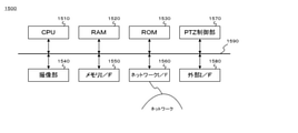
- FIG. 15 is a block diagram showing a main configuration of a network camera 1500 that can be connected to the information processing apparatus 100 according to the present embodiment.
- a CPU 1510 a RAM 1520, a ROM 1530, an image pickup unit 1540, a memory I / F1550, a network I / F1560, a PTZ control unit 1570, and an external I / F1580 are connected to each other via an internal bus 1590.
- Reference numeral 1510 is a CPU, which controls the operation of the network camera 1500.
- the RAM 1520 is a high-speed writable storage device, and is loaded with an OS, various programs, and various data. It is also used as a work area for the OS and various programs.
- the ROM 1530 is a non-volatile read-only storage device, and is used as a permanent storage area for BIOS, various basic programs, and various basic data. An identification ID (such as an IP address) for identifying the network camera 1500 is held in the RAM 1520 or the ROM 1530.
- the image pickup unit 1540 photoelectrically converts an optical image with an image pickup sensor such as a CCD or CMOS and transfers it to a CPU.
- the memory I / F1550 is connected to a recording medium such as an SD card or HDD to write or read video signals and various data.
- the network I / F 1560 bears an I / F for communicating with the information processing apparatus 100 and various clients according to a protocol such as an Internet protocol or ONVIF via the network.
- ONVIF is a protocol formulated by the standardization organization Open Network Video Interface Forum that implements commands for instructing device control and the start of distribution of images and metadata.
- the PTZ control unit 1570 obtains a pan / tilt / zoom state in a PTZ camera having a pan / tilt / zoom mechanism, and performs PTZ control according to an operation instruction.
- Accessories such as a microphone and a viewfinder are connected to the external I / F1580. It does not necessarily have to be directly attached to the camera body, and may be connected from a terminal via a cable, or may be wirelessly connected. When the audio is picked up by the microphone, it is recorded as an audio track integrated with the video signal.
- FIG. 16 is a block diagram showing a configuration of a functional module related to content reception / reproduction of the viewer terminal 1600 that can be connected to the information processing apparatus 100 according to the present embodiment.
- the viewer terminal 1600 includes a communication unit 1601, a playlist acquisition unit 1602, a segment data acquisition unit 1603, a buffer unit 1604, and a reproduction unit 1605.
- the communication means 1601 communicates with the information processing apparatus 100 by a protocol such as HTTP.
- the playlist acquisition unit 1602 makes a playlist acquisition request to the information processing device 100, and acquires the playlist from the information processing device 100. Then, before the reproduction of all the segment data described in the acquired playlist is completed, the playlist acquisition request is retransmitted and the playlist is reacquired (reloaded). If it is stated in the acquired playlist that it is the last playlist, the acquisition of the playlist ends.
- the segment data acquisition unit 1603 acquires segment data in the order described in the acquired playlist. That is, the acquisition request is transmitted to the URL (Uniform Resource Identifier) indicating the file path of the TS file described in the playlist.
- the buffer means 1604 buffers (temporarily holds) the acquired segment data for a certain period of time.
- the reproduction means 1605 reads and reproduces the segment data buffered in the buffer means 1604 in the order described in the playlist.
- FIG. 4 is a block diagram showing a functional module configuration of the switcher terminal 400.
- 401 is a video source thumbnail display means, and a thumbnail image is generated from a video signal (live view) of the video source connected to the information processing device 100 and displayed on the touch panel display of the switcher terminal 400.
- Reference numeral 402 is a main menu display means, and the main menu is displayed on the switcher terminal 400.
- Reference numeral 403 is a volume level display means, and the volume level of the audio signal of the user-selected (switched) video source (hereinafter referred to as “PGM”) among the video sources connected to the information processing apparatus 100 is displayed on the touch panel of the switcher terminal 400.
- Reference numeral 404 is an "ON AIR" indicator display means, and the touch panel of the switcher terminal 400 indicates that the start is instructed by the user and the sequence data consisting of information such as the switched video source and the switched time is output. Show on the display.
- Reference numeral 405 is an output start / end control means, which controls output start / end of sequence data or the like.
- Reference numeral 406 is a video monitoring means, and the video signal (PGM) of the video source selected (switched) by the user is displayed on the monitor unit 506 on the switcher terminal 400 touch panel display.
- 407 is a video source search / addition / deletion means, and searches / adds / deletes a video source that can be connected to the information processing apparatus 100.
- Reference numeral 408 is a switching means, in which one of the video sources connected to the information processing apparatus 100 is selected (switched) as the PGM according to the user's instruction, and the video signal is displayed on the monitor unit 506 on the switcher terminal 400 touch panel display.
- Reference numeral 409 is a camera control means, which generates a camera control command based on a user operation and sends it to a target camera.
- the 410 is a transition means, and controls switching from the video source selected as the PGM to another video source over a certain period of time.
- Reference numeral 411 is a property means for writing / reading properties to a sequence (timeline) of a video source.
- Reference numeral 412 is a device setting means, and sets / adjusts the display text size, screen brightness, volume, WiFi connection, etc. on the switcher terminal 400 touch panel display.
- Reference numeral 413 is a system clock, which keeps time in synchronization with the time server.
- Reference numeral 414 is a data output means, and the generated sequence data is output by SMIL (Synchronized Multimedia Integration Language), CSV (Comma Separated Value), EDL (Edit Decision List), EDL (Edit Decision List), AAF (Data), etc.
- Reference numeral 415 is a programmed camera work means, in which a series of camera work (switching and PTZ control) is programmed for each scene.
- Reference numeral 416 is a camera work executing means, and the camera work programmed by the programmed camera work means 415 is sequentially executed based on the user instruction.
- Some network cameras can be pan / tilt / zoom.
- the information processing apparatus 100 has a PTZ control means for controlling pan / tilt / zoom of such a network camera.
- a PTZ control means for controlling pan / tilt / zoom of such a network camera.
- FIG. 5 is a diagram showing an example of a WEB application screen displayed on the touch panel display of the switcher terminal 400 by the information processing apparatus 100 according to the embodiment of the present invention.
- 501 is a GUI for a switcher application.
- Reference numeral 502 is a menu button for calling the main menu.
- Reference numeral 503 is an audio meter indicating the volume level.
- Reference numeral 504 is an “ON AIR” indicator that indicates whether or not recording (sequence data recording) or broadcasting (streaming) is in progress.
- Reference numeral 505 is a start button for instructing the start (recording or broadcasting start) of "ON AIR". When the start button 505 is pressed to start recording or broadcasting, the start button 505 is replaced with the stop button 505-2.
- Reference numeral 506 is a monitor unit, which is an area for displaying the video (PGM) of the selected (switching) video source.
- Reference numeral 507 is a video source unit, which is an area for displaying thumbnails of switchable video sources.
- the video source thumbnails 5071, 5072, ... Are displayed in the video source unit 507.
- the video source thumbnail is a thumbnail icon indicating a plurality of video sources connected to the information processing apparatus 100 via a network, and displays the video output by each video source as a thumbnail.
- the cameras 1500-1, 1500-2, ... Are video sources, and the video captured by these is displayed as a video source thumbnail in real time.
- the final frame up to that point is displayed in a stationary state, or the so-called “blackness (black screen)" is displayed.
- blackness black screen
- an image taken by three PTZ (pan / tilt / zoom) cameras and one video image are displayed.
- the video image referred to here is, for example, image data that has been captured in advance and stored in a recording medium such as the RAM 120 of the information processing apparatus 100 or online storage. Such video images can also be used as materials for video contents.
- Reference numeral 508 is a plus button, which is a button for searching and adding a video source to be displayed in the video source unit 507.
- Reference numeral 509 is a camera control button for controlling each video source. When the camera control button 509 is pressed by the user, the camera operation panel 600 is displayed. The camera operation panel 600 is displayed for each camera. Further, as a so-called floating window, the position can be moved and displayed.
- 510 is a switching type button that changes the switching type, a cut selection button 510-1 that selects "cut” that is an instant switch, and a transition selection button 510 that selects a "transition” that is a gradual switch with an effect. It is composed of -2.
- the cut selection button 510-1 and the transition selection button 510-2 are so-called toggle buttons that are exclusively (alternatively) selected from each other.
- Reference numeral 511 is a rating button for the user (content creator) to rate the recorded take.
- 512 is a timeline area for displaying a so-called “filmstrip (thumbnail sequence of shots constituting a scene)”.
- Reference numeral 513 is a comment area in the timeline area
- 514 is a time code scale
- 515 is a video source thumbnail display area for displaying (thumbnail) of the video source switched at the timing of the time code in the timeline area.
- the length of each video source thumbnail along the time code scale 514 corresponds to the time length of the "shot”.
- the comment text entered by the user is displayed in the comment area 513.
- Reference numeral 516 is a play button, and when the play button 516 is pressed, the recorded video sequence (live views from each video source are connected and recorded in the RAM 120) is recorded from the timing indicated by the sequence marker 517 on the time code scale 514. It is reproduced and displayed on the monitor unit 506. When the play button 516 is pressed, the play stop button 516-2 is replaced. If there is no reproducible video sequence (when the video sequence is not recorded), the play button 516 is invalidated (grayed out).
- Reference numeral 518 is a property button, and a property panel can be displayed so that a scene title, a take number, etc. can be added or changed to the video sequence displayed on the timeline in the timeline area 512. ..
- Reference numeral 519 is a magnification slider that adjusts the magnification for displaying the timeline.
- Reference numeral 520 is a fader, which is a switching slider for performing a switching operation at the time of transition.
- Reference numeral 521 is a scene title combo box for displaying the scene title.
- Reference numeral 522 is a take number text box for displaying the take number.
- 523 is a programmed camera work button that displays a programmed camera work panel for performing the programmed camera work function. The programmed camera work function will be described later.
- the display of the switcher terminal 400 is configured as a touch panel display integrated with the touch panel, the user can tap (touch down to touch up) or flick (touch down to touch up) a GUI member such as an icon using a finger or a stylus pen.
- Each function can be executed by performing touch gestures such as (moving quickly while touching and touching up). For example, by tapping the thumbnails 5071, 5072, ... Of the video source unit 507, the video source corresponding to the thumbnail can be selected (switched) as the PGM. At this time, a red frame is attached to the thumbnail, indicating that the corresponding video source is selected. Further, the image of the image source is displayed on the monitor unit 506.
- sequence data the ID of the video source (or the video clip generated from the video source) and the tapped time (time code) are recorded.
- start button 505 recording of sequence data and recording of a video sequence (a sequence in which live views of switched video sources are connected in a single connection) are started.
- the video source corresponding to the thumbnail touched later is switched to the so-called preset video (hereinafter referred to as "PST"). ) Is set.
- PST preset video
- the video of the video source set as PST (video of the thumbnail video source touched later) is gradually changed with an effect (transition effect). That is, in the present embodiment, it is possible to instruct the transition by a touch gesture to the touch display means.
- the user can operate “cut (instantaneous switching)" and “transition” according to the difference between "one-point touch” and “two-point touch”, and the operation method can be changed. Easy to understand and convenient.
- the user can also make a transition by manipulating the fader 520. That is, when the fader 520 is operated by the user, the PGM image displayed on the monitor unit 506 is gradually changed to the image of the image source set as PST by the transition means 410 according to the slide amount of the fader 520. Switch.
- the transition control by such a fader operation is in line with the operability of the conventional switcher device, and it is convenient because the transition can be performed at the timing desired by the user.
- the video source switching cut and transition
- the ID of the video source (or video clip) and the switching start and end times (time code) are recorded as sequence data.
- 524 is a transition effect pull-down that allows the transition effect to be selected.
- Transition effects include “dissolve,””wipe,””slide,””squeeze,””iris,” and “zoom.”
- the transition effect pull-down 521 is activated when the transition selection button 510-2 is selected (when the transition selection button 510-2 is not selected, it is grayed out).
- Reference numeral 525 is a duration time up / down for setting a duration time (Duration Time), which is a transition switching time.
- the duration up / down 522 is activated when the transition selection button 510-2 is selected (when the transition selection button 510-2 is not selected, it is grayed out).
- FIG. 6 is a diagram showing an example of a camera operation panel displayed on the touch panel display of the switcher terminal 400 by the information processing apparatus according to the present embodiment.
- the camera operation panel 600 includes an image display unit 601 and a "subject tracking” check box 602, a "tracking during PGM” radio button 603a, a “not tracking during PGM” radio button 603b, a “size setting tracking” check box 604, and " It has a “size setting” pull-down 605, a "connection adjustment” check box 606, a close button 607, a subject designation frame 608, a pan / tilt controller 609, a zoom controller 610, a focus controller 611, and a setting menu button 612.
- the image display unit 601 is an area for displaying the image taken by the corresponding camera.
- the pan / tilt controller 609 is a GUI that imitates a joystick for controlling the pan / tilt of the corresponding camera.
- the zoom controller 610 is a slider for controlling the zoom of the corresponding camera.
- the user can also perform PTZ control of the corresponding camera by performing a pinch-in or pinch-out operation on the image display unit 601. That is, the angle of view (angle) corresponding to the range displayed in the entire area of the image display unit 601 at the time of touch-down by the touch operation (pinch-in) in which two points on the image display unit 601 are touched down at the same time to bring the touch positions closer to each other. ) Can be controlled by the PTZ of the corresponding camera so that it is zoomed out and pan-tilted toward the position of the midpoint between the two touch positions (see FIG. 6 (b)).
- the range near the position of the intermediate point between the two touch down positions is the image display unit 601.
- the PTZ control of zoom-in and pan-tilt can be performed so as to expand to the range displayed in the entire area (see FIG. 6 (c)).
- the user can perform the pan / tilt operation and the zoom operation integrally by touch gestures, which is convenient.
- the following ONVIF command is transmitted to the network camera.
- AreaZoom x1-x0, y1-y0, w1-w0, h1-h0
- x1 and y1 are the coordinates of the midpoint of the two-point touch after the pinch operation
- x0 and y0 are the coordinates of the midpoint of the two-point touch before the pinch operation
- w1 and h1 are the coordinates between the touch points after the pinch operation.
- Width, height, w0, h0 are the width and height between the touch points before the pinch operation.
- the width and height of the entire image display unit 601 are set to 200 and 200, respectively.
- EASE IN / EASE OUT As for PTZ, so-called EASE IN / EASE OUT, such as “starting slow operation, gradually accelerating, decelerating and stopping in the middle", is generally considered to be suitable because of its smooth movement. Therefore, when the PTZ control is performed by the above pinch operation, a speed control command that causes the PTZ operation of EASE IN / EASE OUT may be automatically transmitted within the duration of the PTZ operation. Also, when pan-tilting and zooming are performed integrally, the subject once entered the angle of view by pan-tilting will be cut off from the angle of view again by zooming in (it will not be able to enter the angle of view), or it will be temporarily changed to the angle of view by zooming out.
- the display of each side of the display frame of the image display unit 601 is made different from the case where the limit is not approached.
- the frame surrounding the image display unit 601 has a wide-angle end that clearly displays the boundary so that the inner image is blurred and cannot be zoomed out any further, or a telephoto lens that cannot be zoomed in any further.
- the above notification method by expressing the display frame is one method of intuitively notifying the user of the PTZ limit, and other methods such as displaying a text such as "the limit of zooming out is approaching". It may be a notification method.
- the focus controller 604 is a slider for controlling the focus of the corresponding camera. Depending on the performance of the corresponding camera, the autofocus mode can be set.
- the setting menu button 612 is a button for displaying a menu for setting the white balance, iris, frame rate, etc. of the corresponding camera. Depending on the performance of the corresponding camera, auto white balance, auto iris, etc. can be used.
- the "subject tracking" check box 602 is a check box for setting to automatically track a specific subject in PTZ.
- the technology of the automatic tracking function that controls pan / tilt so that the moving object detected on the screen is continuously captured near the center of the screen has already been put into practical use in the field of surveillance cameras and the like.
- the user can set the corresponding camera to automatically track a specific subject.
- the subject designation frame 608 is superimposed and displayed on the video display unit 601. The user moves the frame by touch operation or the like to track the subject at the position of the frame. Can be set as the subject of.
- the "tracking during PGM” radio button 603a and the "not tracking during PGM” radio button 603b are used to set whether or not to perform the above automatic tracking (automatic PTZ) when the corresponding camera is switched. It is a radio button and is activated when the "subject tracking" check box 602 is selected (checked) (when the "subject tracking” check box 602 is not selected (checked), it is grayed out. Yes).
- the main purpose of the above subject tracking is to keep the subject captured on the screen, which may be awkward and unnatural for camera work. Therefore, it is possible to eliminate the risk of unnatural camera work by not tracking the PGM, which is the image that the viewer sees.
- the "size setting tracking” check box 604 is a check box for setting to keep the "size” and track a specific subject, and the "subject tracking” check box 602 is selected (checked). It is enabled (when the "subject tracking” check box 602 is not selected (checked), it is grayed out).
- the "size” is a representation of how large the subject is on the screen based on a human subject, and is a full shot (FS), a full figure (FF), or a knee shot (KS). , Waist shot (WS), bust shot (BS), up shot (US), close-up (CU) (see FIG. 11).
- the "size setting" pull-down 605 is a pull-down for selecting and setting the above “size”, and is enabled when the "size setting tracking" check box 604 is selected (checked) ("size setting" pull-down 605). If the "Size setting tracking" check box 604 is not selected (checked), it is grayed out).
- the "adjust connection" check box 606 seems to be suitable for switching (cutback) from the video of the video source that was previously PGM when the video of the corresponding camera is switched (when it is set to PGM). It is a check box for setting whether or not to perform automatic PTZ adjusted to, and is enabled when the "size setting tracking" check box 604 is selected (checked) ("size setting tracking"). When the check box 604 is not selected (checked), it is grayed out).
- the connection (switching) will give an unnatural impression. Also, if the "size" of the shot after switching is tighter than the "size" of the shot before switching (for example, when switching from "waist shot” to "bust shot"), the head of the person is the subject. If the length from the top to the top of the screen is not shortened before and after switching, the connection (switching) will be unnatural as well.
- the head of the person is also the subject. It is unnatural if the length from the top to the top of the screen is not long before and after switching. Therefore, when the "Adjust connection" check box 606 is selected, the image of the video source that is the PGM is analyzed to determine the "size” and the length from the top of the person's subject to the top of the screen.
- the corresponding camera is tilt-controlled so that the length from the top of the head of the person to the top of the screen is also the same.
- the set size of the "size setting" pull-down 605 is tighter than the "size” of the PGM, the length from the top of the head of the person to the top of the screen is shorter than that of the PGM. Tilt control the corresponding camera.
- the set size of the "size setting" pull-down 605 is looser than the "size” of the PGM, the length from the top of the head of the person to the top of the screen is longer than that of the PGM. Tilt control the corresponding camera. By doing so, it is possible to eliminate the possibility that the shots before and after the switching become unnatural when the image is switched from the PGM.
- the close button 607 is a button for closing (hiding) the camera operation panel 600.
- the subject designation frame 608 is a sign (GUI) for causing the user to instruct and set the subject at the position of the frame as the subject to be tracked.
- the camera operation panel 600 can be displayed for each camera. Further, as a so-called floating window, the position can be moved and displayed.
- the user can perform the pan / tilt operation and the zoom operation integrally.
- it is extremely convenient because it is easy to intuitively understand how the angle of view is changed by the PTZ control.
- the information processing apparatus 100 is in an image based on a video signal transferred by a transfer method in which data is transferred without confirming reception by a node transmitting from a network camera capable of PTZ.
- the PTZ control of the network camera is performed so as to detect the moving object of the above and keep capturing the detected moving object near the center of the screen. This is because such PTZ control needs to be performed based on substantially real-time live view video, but as described above, the live view video transferred by UDP is suitable for use in the video content to be viewed by the viewer. Therefore, it is possible to output (produce or distribute) high-quality video content by performing information processing such as TCP / IP transfer and HTTP streaming for video data different from the live view video.
- FIG. 11 is a diagram illustrating "size".
- Full shot (FS) is the widest angle of view size for the camera.
- the full figure (FF) is the size that includes from the toes to the top of the head.
- the knee shot (KS) is a size that includes the area from the knee to the top of the head.
- the waist shot (WS) is the size from the waist to the top of the head.
- the bust shot (BS) is the size from the chest to the top of the head.
- the up shot (US) is the size of the face that fills the screen.
- a close-up (CU) is a size that fills the screen with body parts such as eyes, mouth, hands, and feet.
- the information processing device 100 displays a video source thumbnail corresponding to the video source, and changes the video displayed on the monitor unit 506 in response to a switching operation (including a fader operation) by the user.
- a switching operation including a fader operation
- FIG. 7 it is a flowchart showing the flow of the process of generating and recording sequence data when it is in the REC state.
- the processing of this flowchart is realized by the CPU 110 of the information processing apparatus 100 controlling each unit based on an input signal or a program.
- the CPU 110 displays the GUI 501 shown in FIG. 5 on the touch panel display of the switcher terminal 400 (step S701).
- the information processing apparatus 100 is in a state of accepting GUI operations by the user.
- the CPU 110 searches for and displays a list of video sources that can be connected to the network (S703).
- the video source thumbnails of the selected video sources are additionally displayed in the video source unit 507 (S705).
- the CPU 110 displays the camera operation panel 600 (S707).
- the camera operation panel 600 includes a video display unit 601, a pan / tilt controller 602, a zoom controller 603, a focus controller 604, a setting menu button 605, and a close button 606.
- Specifications such as the lens focal length at the wide-angle end and the telephoto end of the zoom, the pan-tilt movable range, and the like are acquired by using the ONVIF protocol and the like described above when the PTZ camera is added as a video source. Further, the ONVIF command or the like is generated according to the operation on the camera operation panel 600 of the user to control the PTZ camera (S708). When the close button 606 is pressed by the user (YES in S709), the camera operation panel 600 is closed (S710).
- the CPU 110 sends the video source connected to the information processing apparatus 100 to the video source (the video source displayed as a thumbnail in the video source unit 507).
- a command instructing the start of recording to online storage, recording media, or the like is transmitted (S712).
- the scene title combo box 515 is blank (YES in S713)
- the scene title input panel is displayed to prompt the user to input the scene title (S714).
- the scene title is a combination of the title (program title) of the video content as the "finished product” and the scene number (scene number), for example, "Watanabe family wedding scene 1".
- the take number of the take number text box 516 is the latest take number of the scene title plus one (S715). Further, the start button 505 is replaced with the stop button 505-2 (S716). Further, the generation / recording of the sequence data including the ID of the video source (or video clip) switched at that time and the switched time (time code) is started (S717).
- a URL Uniform Resource Identifier
- a URL can be used as the ID of the video source or the video clip.
- a so-called film strip in which the names or thumbnails of the switched video sources are arranged according to the time code is displayed (S718).
- the CPU 110 displays the video of the video source corresponding to the video source thumbnail on the monitor unit 506 (S720).
- a red frame is attached to the thumbnail (S721) to indicate that the corresponding video source is selected (so-called “Tally display”).
- the time (time code) is acquired from the system clock 413 (S722).
- the user switches to the video source corresponding to the first touched thumbnail (S724), and then touches the thumbnail.
- the video source corresponding to the thumbnail is set to PST (preset video) (S725).
- Thumbnails set to PST may be displayed with, for example, a blinking red frame.
- the PGM image displayed on the monitor unit 506 is PST according to the slide amount of the fader 520.
- the effect (transition effect) at the time of switching the effect selected by the user pressing the effect change button 510 is used.
- “dissolve” may be set as the initial value of the transition effect. This is because it is a commonly used transition effect.
- the fader 520 is not operated by the user (NO in S726) and the thumbnail touched later is touched and touched up from the thumbnail touched first (YES in S728), the user-specified Duration Time (YES in S728).
- the PGM image is gradually switched to the PST image (S729). Then, the switching of the video source is recorded as sequence data (S730).
- the Duration Time is specified by selecting a numerical value in the "Auto Transition Duration Time" combo box of the switching effect selection panel displayed by pressing the effect change button 510.
- the stop button 505-2 When the stop button 505-2 is pressed by the user (YES in S731), the video source connected to the information processing apparatus 100 via the network (the video source displayed as a thumbnail on the video source unit 507) is transferred to the recording medium. A command instructing the stop of recording of is transmitted (S732). Further, the stop button 505-2 is replaced with the start button 505 (S733). Further, the recording of the sequence data is stopped (S734).
- the menu button 502 is pressed by the user (YES in S735), the main menu is displayed (S736).
- the sequence data is saved or output to the user-specified location (S738). Further, when the "end" command is selected by the user (YES in S739), the processing of this flow is terminated.
- FIG. 12 shows an example of sequence data recorded or output by the information processing apparatus 100 according to the present embodiment.
- the data has a structure described in SMIL (Synchronized Multimedia Integration Language) format.
- SMIL Synchronized Multimedia Integration Language
- SMIL is a language for synchronizing the reproduction of various data formats such as moving images, sounds, and characters, which is recommended to be standardized by W3C (World Wide Web Consortium).
- W3C World Wide Web Consortium
- the meta attribute of the ⁇ head> element defines data properties (program title, scene number, take number, rating, remarks / memo, etc.) and is used to assign values to those properties.
- the layout attribute of the ⁇ head> element is used to determine the display position of the object.
- ⁇ layout type "text / smile-basic-layout"> ⁇ /layout>, the default layout value can be applied to all the objects.
- Information related to temporal behavior is described in the ⁇ body> element.
- an object that is continuously reproduced in time is described under the ⁇ seq> element of the child hierarchy. That is, the sequence of the switched video source (video clip) is described as a ⁇ video> element in the child hierarchy of the ⁇ seq> element.
- Each ⁇ video> element specifies a unique ID that identifies the output file from the video source by the src attribute.
- UMID Unique Material Ideas
- SMPTE Society of Motion Picture and Television Engineers, American Society of Motion Picture and Television Engineers
- the switching insertion start position (in point) in the video clip (each output file from the video source) is specified by the clipBegin attribute, and the insertion end position (out point) is specified by the clipEnd attribute.
- the data format shown in FIG. 12 is merely an example, and various other formats are possible. For example, it may be a data format such as a CSV (Comma Separated Value) format, an EDL (Edit Decision List), or an AAF (Advanced Autouring Form), or it may be a newly defined data format.
- CSV Common Separated Value
- EDL Edit Decision List
- AAF Advanced Autouring Form
- the existing video editing application can read the data and edit the video.
- Typical video editing applications include Premiere Pro from Adobe, USA and Final Cut Pro from Apple, USA.
- FIG. 14 shows an example of EDL data.
- FIG. 14 shows an example in which program recording (recording of sequence data) is started 20 seconds after the start of video data output of each video source.
- 1401 represents the title of the sequence.
- 1402 indicates whether the time code of the edited sequence is in the drop frame format or the non-drop frame format.
- 1403 indicates whether the time code of the sequence of the video clip of each video source is the drop frame format or the non-drop frame format.
- 1404 represents a shot number.
- 1405 represents the ID of the video source.
- 1406 represents the configuration of "audio 2 channels / video”.
- 1407 represents a switching type.
- 1408 represents the time code of the in-point of the video clip of the video source.
- 1409 represents the time code of the out point of the video clip of the video source.
- 1410 represents the time code of the in-point of the edited video clip (video content).
- 1411 represents the time code of the out point of the edited video clip (video content).
- FIG. 8 is a flowchart showing an example of information processing in which the information processing apparatus 100 according to the embodiment of the present invention generates and distributes a playlist based on information on which video source is switched at what timing.
- a browser is activated on a user terminal (PC, tablet, smartphone, etc.), and the URL (Uniform Information Locator) of the "video content production service" provided by the information processing apparatus 100 according to the embodiment of the present invention is input or instructed.
- the information processing device 100 displays the home page on the user terminal (display unit) (S801).
- the "creator user login” button is displayed (S802).
- the user instructs the "creator user login” button YES in S803
- the user authenticates with the user ID, password, etc.
- the user terminal A GUI of a switcher application such as 501 in FIG. 5 is displayed on the display (S806).
- the video sources that can be connected to the network are searched and displayed in a list (S808).
- the video source thumbnails of the selected video sources are additionally displayed in the video source unit 507 (S810).
- the camera operation panel 600 When the operation by the user is the pressing of the camera control button of the PTZ camera (YES in S811), the camera operation panel 600 is displayed (S812). As described above, the camera operation panel 600 has an image display unit 601, a "subject tracking” check box 602, a “tracking even during PGM” radio button 603a, a “not tracking during PGM” radio button 603b, and “size setting tracking”. It has a check box 604, a "size setting” pull-down 605, a "connect adjustment” radio button 606a, a “no connection adjustment” radio button 606b, a close button 607, and a subject designation frame 608.
- a control command corresponding to the operation is transmitted to control the PTZ camera of the corresponding camera (S814).
- the corresponding PTZ camera is set to the tracking mode (S816).
- the thumbnail of the corresponding PTZ camera in the video source unit 507 indicates that the tracking mode is set.
- a specific memory is stored in the video source connected to the user terminal via the network (video source displayed as a thumbnail in the video source unit 507).
- a command instructing the output of video data to the area is transmitted (S820).
- segment data is generated by subdividing the video data output to the storage area (S821).
- a playlist describing a file path that refers to the segment data generated from the video data of the video source being switched at that time is generated (S822), and registered / saved in the distribution directory (folder) (S823). ..
- the start button 505 is replaced with the stop button 505-2 (S824).
- the generation / recording of the sequence data including the ID of the video source (or video clip) switched at that time and the switched time (time code) is started (S825).
- the time T1 switched from the system clock 308 is acquired (S827).
- the switching type set by the switching type button 510 is determined, and when "cut" is selected (YES in S828), first, the video of the video source corresponding to the video source thumbnail is displayed on the monitor unit 506. Display (S829).
- a red frame is attached to the thumbnail (S830) to indicate that the corresponding video source is selected (so-called “tally display”).
- the imaging time attached to the segment data generated from the switched video source is compared with the switching time T1, and the file path to the segment data related to the video captured after the time T1 is described in the playlist. Is generated (S831).
- the PGM image displayed on the monitor unit 506 is the image of the image source corresponding to the tapped image source thumbnail (NO).
- PST is gradually switched to the user-specified transition time (switching time) according to the user-specified effect (switching effect) (S832).
- a red frame is added to the tapped video source thumbnail (S833).
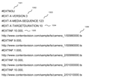
- FIG. 13 shows an example of a playlist in m3u format.
- FIG. 13 shows an example of switching from Camera_1 to Camera_2 at 999 seconds (16 minutes 39 seconds) from the start of the program.
- the segment data related to the images of Camera_1 and Camera_2 can be found at http: // www. contentvision. com / sample / ts / camera_1 / http: // www. contentvision. com / sample / ts / camera_2 / It shall be registered and saved in. Further, it is assumed that the number of seconds in milliseconds (1/1000) at the time when the imaging of the image related to the data is started is attached to the segment data as the file name.
- 1301 represents a file format.
- 1302 represents the version number of the file format.
- 1303 indicates the number of the segment data (TS file) at the head of the list as a whole.
- 1304 indicates how many seconds or less each segment data (TS file) is divided.
- 1305 represents the time length of the segment data (TS file) indicated by the file path of the next line.
- 1306 represents a file path (URL) to the segment data (TS file).
- TCP is used for the transfer of video data in HTTP streaming, and it is possible for the viewer to view high-quality video content with suppressed noise.
- the programmed camera work function of the information processing apparatus of the present embodiment is a function in which a user is made to program (input) a series of camera works in advance, and the programmed camera works are sequentially executed according to a user instruction. Camera work input and execution instructions are performed by displaying the programmed camera work panel.
- FIG. 9 shows an example of a programmed camera work panel.
- the programmed camera work panel is displayed as a so-called floating window on the display of the switcher terminal 400 when the programmed camera work button 523 is pressed by the user.
- the programmed camera work panel 901 has a monitor unit 902, a REC button 903, an EDIT button 904, a NEXT button 905, a camera work column 906, an event number column 907, a text column 908, a BACK button 909, a SKIP button 910, and a pop-up 911.
- the camera work column 906 is a column showing the camera work in the order of progress.
- camera work refers to cut switching or transition of a video source or PTZ control for a PTZ camera.
- the event number column 907 is a column representing a number in the order in which camera work is executed.
- the text field 908 is a field for displaying texts (scenarios, progress tables, scripts, etc.) that serve as a guideline for timing when camera work is executed.
- the displayed text may be, for example, the lyrics of a song, the scale progression, the number of beats, or the number of measures. Further, it may be input by the user from an operation unit such as a keyboard, may be read from a file, may be scanned from a paper manuscript, or may be photographed.
- the monitor unit 902 is an area for displaying the video signal (PGM) of the selected (switching) video source.
- the REC button 903 is a button for instructing the start of recording (sequence data recording).
- the EDIT button 904 is a button for setting the mode in which the camera work field and the text field can be edited (changed / inserted / deleted / changed in order).
- the NEXT button 905 is a button for executing the focused camera work and moving the focus to the next camera work.
- the BACK button 909 is a button for moving the focus to the previous camera work.
- the SKIP button 910 is a button for moving the focus to the next camera work.
- Pop-up 911 is a "speech balloon” that is displayed near the cursor position in the text and has a "BS button”, a "break block button”, and a "keyboard button”, and is displayed for editing the text.
- the user can set the programmed camera work panel 901 to the EDIT mode (editable mode) and set "video source switching (switching)" and "PTZ control" in the camera work column. Further, the camera work executed in the main window (GUI501 in FIG. 5) is retained as data, and can be read into the programmed camera work panel 901 and used as the programmed camera work. In other words, for example, after switching or PTZ control in the first take of a certain scene, the camera work is used as programmed camera work in the subsequent takes (retakes), reducing the trouble and mistakes of camera work operation. can do.
- FIG. 10 is a flowchart showing a flow of processing related to the programmed camera work function of the information processing apparatus 100 according to the present embodiment.
- the programmed camera work button 523 is pressed by the user, the programmed camera work panel 901 is displayed as a so-called floating window (S1001).
- the information processing apparatus 100 first determines whether or not there is data of camera work executed in the main window, and if there is such data (YES in S1002), the programmed camera work data (on the programmed camera work panel). (S1003) to compare with the camera work data displayed in.
- a PTZ dialog having a GUI similar to that of the camera control panel 601 is displayed (S1020).
- the band indicating the cut line and PTZ in the camera work column, the combo box indicating the switching time, and PTZ are executed.
- a thumbnail showing the later angle of view is displayed (S1022).
- the combo box indicating the switching time has a default value. The user can tap the combo box to change the value.
- the cursor When the text field is long-pressed by the user (YES in S1023), the cursor is displayed in the text (S1024). In addition, a pop-up (speech balloon) is displayed (S1025).
- the pop-up has a BS button, a break block button, and a keyboard button.
- a backspace Back Space for deleting one character before the cursor is performed (S1027). If the deletion target is a "cut line" instead of a character, the text of the text block where the cursor is located is combined with the previous block, and the text block corresponding to the subsequent event number is shifted forward one by one. ..
- the menu is displayed (S1033).
- the menu has commands of "read text”, “save programmed camera work data”, and "read programmed camera work data”.
- the file reading window is displayed (S1035).
- the file reading window has "overwrite” and “insert” options (radio buttons) and "OK” and "cancel” buttons.
- the "OK” button is disabled (grayed out).
- "Overwrite” is selected by the user and the file is read (YES in S1036), all the text in the text field is overwritten with the text of the read file (S1037).
- the data file reading window is displayed (S1043).
- the data file reading window has a check box "Read executed camera work” and "OK” and “Cancel” buttons. If the check box is not checked or the file is not selected in the window, the "OK” button is disabled (grayed out). When the check box is checked, the file selection in the window is invalidated (grayed out).
- the camera work data is read (YES in S1044), the camera work column is overwritten (S1045).
- the programmed camera work panel is put into the execution mode (S1047). Specifically, the REC button and the NEXT button are enabled.
- the NEXT button is tapped by the user (YES in S1048), the camera work of the focused row is executed and the focus is moved to the next row (S1049).
- the camera work of the last line is executed (YES in S1050), none of the lines is focused, and the NEXT button is disabled (grayed out) (S1051).
- the REC button is tapped by the user (YES in S1052), REC is started (S1053).
- the operation at the time of REC is the same as that at the time of the REC instruction in step S711 of FIG.
- the focus is moved to that line (S1055).
- the close button is pressed by the user, or when any part of the main panel is tapped (YES in S1056), the programmed camera work panel is closed (S1057).
- the REC / REC stop and the display / non-display of the programmed camera work panel are independent of each other. For example, the REC will continue even during the REC when closing the programmed camera work panel.
- the data used for saving and reading the programmed camera work is described by assigning a number (event number) to the switching of the video source and the PTZ control, and relating it to the progress table text and the content in a timely manner. Since it is common with sequence data in that "switching of video source" is described, the format of sequence data may be expanded and used. An example of extending sequence data described in SMIL (Synchronic Multimedia Integration Language) format to programmed camera work data will be described below.
- Event_Num attribute is added to each ⁇ video> element, and the order (event number) in which the camera work is executed is described.
- a PTZ control is described in the child hierarchy of the ⁇ seq> element, for example, as an ⁇ onvif> element.
- the user can program a series of camera works in advance and instruct the NEXT button to execute them sequentially in a preset order. As a result, it is possible to reduce the time and effort of camera work operation and operation mistakes.
- the user can set the timing of the camera work execution instruction in comparison with the progress table and the script, and the operability is further improved.
- the camera work executed in the main window can be used as programmed camera work. This reduces the time and effort required to program (input / set) camera work.
- the above texts can be used to publish and explain the contents of video content, plans and plans, and advertisers and collaborators.
- An embodiment in which staff or the like is recruited or matched is also suitable. In this way, it will be possible to build and operate a platform for planning, financing, production, distribution, distribution, etc., centered on the creation of video content. Also, when the camera work programmed in contrast to the above text (scenario, progress chart, script, song lyrics, storyboard, musical score, etc.) is executed and video content is produced, that text is diverted. Also suitable is an embodiment in which advertisers, collaborators, and staff who have been matched or the like are notified or made accessible to all or part of the produced video content. When doing so, the action (action / execution) of the advertiser, collaborators, staff, etc. should be encouraged by the notification and access (playback, viewing, confirmation, etc.) to all or part of the video content. This has the effect of accelerating the progress of projects related to video content production and distribution.
- Sequence data that refers to the switched parts in the switched order is created.
- This sequence data also has the property of a so-called "playlist" that indicates the playback order of a plurality of video clips (parts), so if the video player plays the video clips (parts) according to the sequence data, it will be recorded. You can watch and play the video content of the event. For example, when the sequence data is described in SMIL format, the video content can be played back using the WEB browser as a video player. If the sequence data is in a data format that can be read by a video editing device (video editing application), the video clip from the video source is used as the material data, and the video content of the recorded event is used as a single video file. Can be exported (output).
- sequence data is generated for each recording (one take of one scene), when the video content consists of a plurality of scenes, the sequence data for each scene is made to correspond to a plurality of scenes ().
- Combine sequence data For example, in the sequence data example of FIG. 12 (example of sequence data described in SMIL format), the elements in the hierarchy below the ⁇ body> element are of the "scene number" described in the meta attribute of the ⁇ head> element. When combined in order, multiple scenes are combined as a playlist that is played back in order of scene number.
- a WEB page having an area of a text editor for editing SMIL and a monitor area for reproducing and displaying the SMIL makes it possible to configure a WEB application for video editing.
- the information processing device 100 refers to a file in which sequence data is written on the moving image server side, and is switched by the information processing device 100 of the video clip in which the video data of the video source is written based on the data. If the images of the above parts are sequentially transmitted, live distribution can be performed (due to a slight delay) even during event recording (sequence data is being written).
- the information processing apparatus 100 is a substantially real-time live view video transferred by a transfer method in which data is transferred without confirming reception by a node transmitting from a plurality of video sources including a network camera.
- the video source is switched (switching) based on the above, and the video content is created or distributed based on the information on which video source was switched at what timing and the video data output from the video source. ..
- By adopting such a configuration while switching the video source in near real time according to the progress of "events" such as ceremonial occasions such as ceremonial occasions and dramas (dramas), video data with little deterioration in quality due to network transmission is used as the material. It will be possible to create or distribute the video content that has been created. In this way, labor such as line setting and equipment cost can be reduced, and video content production can be simplified, speeded up, and cost reduced. That is, an information processing device suitable for creating or distributing video content by switching video sources including a network camera is realized.
- the present invention supplies software (program) that realizes the functions of the above-described embodiment to a system or device via a network or various storage media, and a computer (or CPU, MPU, etc.) of the system or device. Is also realized by the process of reading and executing the program. Therefore, in order to realize the functional processing of the present invention on a computer, the program code itself installed on the computer also realizes the present invention. That is, the present invention also includes the computer program itself for realizing the functional processing of the present invention.
- the present invention can also be realized as a so-called WEB application using a WEB browser. Therefore, the WEB server pointed to by the URL (Uniform Resource Identifier) constitutes the implementation of the present invention regardless of whether it is a single piece of hardware.
- Sequence recording start / end control means 406 ... PGM video display means, 407 ... video source search / add / delete means, 408 ... switching means, 409 ... camera control means, 410 ... transition means, 411 ... property means, 412 ... device setting means, 413 ... system clock, 414 ... Sequence data output means, 415 ... programmed camera work means, 416 ... camera work execution means, 501 ... GUI, 502 ... menu button, 503 ... audio meter, 504 ... ON AIR indicator, 505 ... start button, 506 ... monitor unit, 507 ... Video source section, 508 ... Plus button, 509 ... Camera control button, 510 ... Switching type button, 511 ...
- RAM (camera), 1530 ... ROM (camera), 1540 ... Imaging unit (camera), 1550 ... Memory I / F (camera), 1560 ... Network I / F (camera), 1570 ... PTZ control unit (Camera), 1580 ... External I / F (camera), 1590 ... Internal bus (camera), 1601 ... Viewer terminal communication means, 1602 ... Playlist acquisition means, 1603 ... Segment data acquisition means, 1604 ... Buffer means, 1605 ... Reproduction means
Landscapes
- Engineering & Computer Science (AREA)
- Signal Processing (AREA)
- Multimedia (AREA)
- Databases & Information Systems (AREA)
- Human Computer Interaction (AREA)
- Computer Security & Cryptography (AREA)
- Studio Devices (AREA)
- Two-Way Televisions, Distribution Of Moving Picture Or The Like (AREA)
- Closed-Circuit Television Systems (AREA)
- Studio Circuits (AREA)
- Television Signal Processing For Recording (AREA)
- Debugging And Monitoring (AREA)
- Signal Processing For Digital Recording And Reproducing (AREA)
Priority Applications (13)
| Application Number | Priority Date | Filing Date | Title |
|---|---|---|---|
| US18/011,040 US12003882B2 (en) | 2020-08-11 | 2021-08-02 | Information processing devices, methods, and computer-readable medium for performing information processing to output video content using video from multiple video sources including one or more pan-tilt-zoom (PTZ)-enabled network cameras |
| NZ795958A NZ795958B2 (en) | 2021-08-02 | Information processing device, information processing program, and recording medium | |
| CN202311794498.9A CN117544739A (zh) | 2020-08-11 | 2021-08-02 | 信息处理装置、信息处理程序及记录介质 |
| AU2021325471A AU2021325471B2 (en) | 2020-08-11 | 2021-08-02 | Information processing device, information processing program, and recording medium |
| JP2022542801A JP7178035B2 (ja) | 2020-08-11 | 2021-08-02 | 情報処理装置、情報処理プログラムおよび記録媒体 |
| EP21855893.0A EP4199383B1 (en) | 2020-08-11 | 2021-08-02 | Information processing device, information processing program, and recording medium |
| CN202180047947.6A CN115836517B (zh) | 2020-08-11 | 2021-08-02 | 信息处理装置、信息处理程序及记录介质 |
| JP2022175911A JP7730164B2 (ja) | 2020-08-11 | 2022-11-02 | 情報処理装置、情報処理プログラムおよび記録媒体 |
| AU2023203194A AU2023203194B2 (en) | 2020-08-11 | 2023-05-22 | Information processing device, information processing program, and recording medium |
| JP2023112744A JP7569055B2 (ja) | 2020-08-11 | 2023-07-10 | 情報処理装置、情報処理プログラムおよび記録媒体 |
| US18/387,716 US12212883B2 (en) | 2020-08-11 | 2023-11-07 | Information processing devices, methods, and computer-readable medium for performing information processing to output video content using video from mutiple video sources |
| JP2024152111A JP7730204B2 (ja) | 2020-08-11 | 2024-09-04 | 情報処理装置、情報処理プログラムおよび記録媒体 |
| JP2025131519A JP2025163209A (ja) | 2020-08-11 | 2025-08-06 | 情報処理装置、情報処理プログラムおよび記録媒体 |
Applications Claiming Priority (4)
| Application Number | Priority Date | Filing Date | Title |
|---|---|---|---|
| JP2020-135599 | 2020-08-11 | ||
| JP2020135599 | 2020-08-11 | ||
| JP2020164204 | 2020-09-30 | ||
| JP2020-164204 | 2020-09-30 |
Related Child Applications (2)
| Application Number | Title | Priority Date | Filing Date |
|---|---|---|---|
| US18/011,040 A-371-Of-International US12003882B2 (en) | 2020-08-11 | 2021-08-02 | Information processing devices, methods, and computer-readable medium for performing information processing to output video content using video from multiple video sources including one or more pan-tilt-zoom (PTZ)-enabled network cameras |
| US18/387,716 Continuation US12212883B2 (en) | 2020-08-11 | 2023-11-07 | Information processing devices, methods, and computer-readable medium for performing information processing to output video content using video from mutiple video sources |
Publications (1)
| Publication Number | Publication Date |
|---|---|
| WO2022034814A1 true WO2022034814A1 (ja) | 2022-02-17 |
Family
ID=80247829
Family Applications (1)
| Application Number | Title | Priority Date | Filing Date |
|---|---|---|---|
| PCT/JP2021/028523 Ceased WO2022034814A1 (ja) | 2020-08-11 | 2021-08-02 | 情報処理装置、情報処理プログラムおよび記録媒体 |
Country Status (7)
| Country | Link |
|---|---|
| US (2) | US12003882B2 (https=) |
| EP (1) | EP4199383B1 (https=) |
| JP (6) | JP7178035B2 (https=) |
| CN (2) | CN117544739A (https=) |
| AU (2) | AU2021325471B2 (https=) |
| NZ (1) | NZ800172A (https=) |
| WO (1) | WO2022034814A1 (https=) |
Cited By (2)
| Publication number | Priority date | Publication date | Assignee | Title |
|---|---|---|---|---|
| CN114840776A (zh) * | 2022-07-04 | 2022-08-02 | 北京拓普丰联信息科技股份有限公司 | 一种数据发布源收录的方法、装置、电子设备及存储介质 |
| JP7531677B1 (ja) | 2023-10-13 | 2024-08-09 | セーフィー株式会社 | システム、方法、及びプログラム |
Families Citing this family (1)
| Publication number | Priority date | Publication date | Assignee | Title |
|---|---|---|---|---|
| WO2025115833A1 (ja) * | 2023-11-28 | 2025-06-05 | 日本放送協会 | 映像生成装置、切出領域決定装置及びプログラム |
Citations (11)
| Publication number | Priority date | Publication date | Assignee | Title |
|---|---|---|---|---|
| JP2009200965A (ja) * | 2008-02-22 | 2009-09-03 | Canon Inc | 映像配信装置及びその制御方法、並びに映像配信システム |
| JP2009200966A (ja) * | 2008-02-22 | 2009-09-03 | Canon Inc | 表示処理装置及びその制御方法と映像記録装置及び表示処理システム |
| JP2009200964A (ja) * | 2008-02-22 | 2009-09-03 | Canon Inc | 表示処理装置及びその制御方法並びに表示処理システム |
| JP2012014420A (ja) | 2010-06-30 | 2012-01-19 | Canon Inc | 映像コンテンツ作成装置、方法及びプログラム |
| JP2015062311A (ja) | 2014-11-26 | 2015-04-02 | ソニー株式会社 | カメラシステム、映像選択装置及び映像選択方法 |
| JP2016009881A (ja) | 2014-06-20 | 2016-01-18 | 日本放送協会 | Ipベースの映像伝送装置および放送システム |
| JP5909546B2 (ja) | 2012-04-03 | 2016-04-26 | 株式会社ビットメディア | 映像ストリーミング配信のための装置及び方法 |
| WO2016132864A1 (ja) * | 2015-02-18 | 2016-08-25 | 株式会社日立国際電気 | 映像監視システムおよび映像監視方法 |
| JP2017208702A (ja) * | 2016-05-18 | 2017-11-24 | キヤノン株式会社 | 情報処理装置及びその制御方法、撮影システム |
| JP2017536021A (ja) * | 2014-10-08 | 2017-11-30 | フラウンホファー ゲセルシャフト ツール フェールデルンク ダー アンゲヴァンテン フォルシュンク エー.ファオ. | ビデオ出力データストリームを生成する装置、ビデオソース、ビデオシステム、およびビデオ出力データストリームとビデオソースデータストリームとを生成する方法 |
| JP6490284B2 (ja) | 2018-06-01 | 2019-03-27 | 株式会社インフォシティ | コンテンツ配信システム |
Family Cites Families (28)
| Publication number | Priority date | Publication date | Assignee | Title |
|---|---|---|---|---|
| JP3684525B2 (ja) * | 1998-02-19 | 2005-08-17 | 富士通株式会社 | 多画面合成方法及び多画面合成装置 |
| JP2002185837A (ja) * | 2000-12-18 | 2002-06-28 | Oyo Keisoku Kenkyusho:Kk | ロボットカメラ装置 |
| GB2388266B (en) * | 2002-04-30 | 2005-07-27 | Hewlett Packard Co | Improvements in and relating to camera controls |
| JP4479227B2 (ja) * | 2003-11-19 | 2010-06-09 | ソニー株式会社 | 音声集音・映像撮像装置および撮像条件決定方法 |
| JP2005165991A (ja) * | 2003-11-28 | 2005-06-23 | Hitachi Kokusai Electric Inc | 映像情報制作方法 |
| JP2006086671A (ja) * | 2004-09-15 | 2006-03-30 | Hitachi Ltd | 自動追尾機能を有する撮像装置 |
| JP2007067510A (ja) * | 2005-08-29 | 2007-03-15 | Toshiba Corp | 映像撮影システム |
| JP2007158680A (ja) * | 2005-12-05 | 2007-06-21 | Victor Co Of Japan Ltd | 追尾撮像装置およびこれを利用した追尾撮像システム |
| AU2008204833A1 (en) * | 2007-01-09 | 2008-07-17 | Vidyo, Inc. | Improved systems and methods for error resilience in video communication systems |
| JP2009060542A (ja) * | 2007-09-03 | 2009-03-19 | Sharp Corp | データ送信装置、データ送信方法、視聴環境制御装置、視聴環境制御システム、及び視聴環境制御方法 |
| KR101539043B1 (ko) * | 2008-10-31 | 2015-07-24 | 삼성전자주식회사 | 인물 구도 제안 영상 촬영 장치 및 방법 |
| JP5185794B2 (ja) * | 2008-12-01 | 2013-04-17 | シャープ株式会社 | 無線伝送システム |
| US8274544B2 (en) * | 2009-03-23 | 2012-09-25 | Eastman Kodak Company | Automated videography systems |
| US20140101700A1 (en) * | 2011-01-31 | 2014-04-10 | New Vad, Llc | Touch screen video switching system |
| JP2012257173A (ja) | 2011-06-10 | 2012-12-27 | Canon Inc | 追尾装置、追尾方法及びプログラム |
| JP5979550B2 (ja) | 2012-02-24 | 2016-08-24 | パナソニックIpマネジメント株式会社 | 信号処理装置 |
| US8917309B1 (en) * | 2012-03-08 | 2014-12-23 | Google, Inc. | Key frame distribution in video conferencing |
| JP2014204279A (ja) * | 2013-04-04 | 2014-10-27 | ソニー株式会社 | 映像切替え装置、映像切替え方法、プログラム、及び、情報処理装置 |
| JP6327809B2 (ja) | 2013-08-20 | 2018-05-23 | キヤノン株式会社 | 受信装置、制御方法及びプログラム |
| KR102101438B1 (ko) * | 2015-01-29 | 2020-04-20 | 한국전자통신연구원 | 연속 시점 전환 서비스에서 객체의 위치 및 크기를 유지하기 위한 다중 카메라 제어 장치 및 방법 |
| CN108476280B (zh) * | 2016-01-15 | 2019-06-18 | 富士胶片株式会社 | 摄像系统、摄像装置及摄像装置的工作方法 |
| JP6920578B2 (ja) | 2016-03-02 | 2021-08-18 | パナソニックIpマネジメント株式会社 | 映像ストリーミング装置、映像編集装置および映像配信システム |
| US10631115B2 (en) | 2016-08-31 | 2020-04-21 | Harman International Industries, Incorporated | Loudspeaker light assembly and control |
| EP3520422B1 (en) | 2016-09-30 | 2022-11-02 | British Telecommunications public limited company | Viewer importance adaptive bit rate delivery |
| US20180160025A1 (en) * | 2016-12-05 | 2018-06-07 | Fletcher Group, LLC | Automatic camera control system for tennis and sports with multiple areas of interest |
| US10645463B2 (en) * | 2017-05-31 | 2020-05-05 | Cisco Technology, Inc. | Efficient multicast ABR reception |
| EP3528469B1 (en) | 2018-02-14 | 2021-06-30 | Tata Consultancy Services Limited | Adaptive restful real-time live media streaming |
| JP2019201266A (ja) | 2018-05-15 | 2019-11-21 | マクセル株式会社 | 自動追尾録画システムおよび録画制御装置 |
-
2021
- 2021-08-02 AU AU2021325471A patent/AU2021325471B2/en active Active
- 2021-08-02 CN CN202311794498.9A patent/CN117544739A/zh active Pending
- 2021-08-02 EP EP21855893.0A patent/EP4199383B1/en active Active
- 2021-08-02 WO PCT/JP2021/028523 patent/WO2022034814A1/ja not_active Ceased
- 2021-08-02 CN CN202180047947.6A patent/CN115836517B/zh active Active
- 2021-08-02 JP JP2022542801A patent/JP7178035B2/ja active Active
- 2021-08-02 NZ NZ800172A patent/NZ800172A/en unknown
- 2021-08-02 US US18/011,040 patent/US12003882B2/en active Active
-
2022
- 2022-11-02 JP JP2022175911A patent/JP7730164B2/ja active Active
-
2023
- 2023-03-10 JP JP2023037178A patent/JP7299665B2/ja active Active
- 2023-05-22 AU AU2023203194A patent/AU2023203194B2/en active Active
- 2023-07-10 JP JP2023112744A patent/JP7569055B2/ja active Active
- 2023-11-07 US US18/387,716 patent/US12212883B2/en active Active
-
2024
- 2024-09-04 JP JP2024152111A patent/JP7730204B2/ja active Active
-
2025
- 2025-08-06 JP JP2025131519A patent/JP2025163209A/ja active Pending
Patent Citations (11)
| Publication number | Priority date | Publication date | Assignee | Title |
|---|---|---|---|---|
| JP2009200965A (ja) * | 2008-02-22 | 2009-09-03 | Canon Inc | 映像配信装置及びその制御方法、並びに映像配信システム |
| JP2009200966A (ja) * | 2008-02-22 | 2009-09-03 | Canon Inc | 表示処理装置及びその制御方法と映像記録装置及び表示処理システム |
| JP2009200964A (ja) * | 2008-02-22 | 2009-09-03 | Canon Inc | 表示処理装置及びその制御方法並びに表示処理システム |
| JP2012014420A (ja) | 2010-06-30 | 2012-01-19 | Canon Inc | 映像コンテンツ作成装置、方法及びプログラム |
| JP5909546B2 (ja) | 2012-04-03 | 2016-04-26 | 株式会社ビットメディア | 映像ストリーミング配信のための装置及び方法 |
| JP2016009881A (ja) | 2014-06-20 | 2016-01-18 | 日本放送協会 | Ipベースの映像伝送装置および放送システム |
| JP2017536021A (ja) * | 2014-10-08 | 2017-11-30 | フラウンホファー ゲセルシャフト ツール フェールデルンク ダー アンゲヴァンテン フォルシュンク エー.ファオ. | ビデオ出力データストリームを生成する装置、ビデオソース、ビデオシステム、およびビデオ出力データストリームとビデオソースデータストリームとを生成する方法 |
| JP2015062311A (ja) | 2014-11-26 | 2015-04-02 | ソニー株式会社 | カメラシステム、映像選択装置及び映像選択方法 |
| WO2016132864A1 (ja) * | 2015-02-18 | 2016-08-25 | 株式会社日立国際電気 | 映像監視システムおよび映像監視方法 |
| JP2017208702A (ja) * | 2016-05-18 | 2017-11-24 | キヤノン株式会社 | 情報処理装置及びその制御方法、撮影システム |
| JP6490284B2 (ja) | 2018-06-01 | 2019-03-27 | 株式会社インフォシティ | コンテンツ配信システム |
Non-Patent Citations (1)
| Title |
|---|
| See also references of EP4199383A4 |
Cited By (3)
| Publication number | Priority date | Publication date | Assignee | Title |
|---|---|---|---|---|
| CN114840776A (zh) * | 2022-07-04 | 2022-08-02 | 北京拓普丰联信息科技股份有限公司 | 一种数据发布源收录的方法、装置、电子设备及存储介质 |
| JP7531677B1 (ja) | 2023-10-13 | 2024-08-09 | セーフィー株式会社 | システム、方法、及びプログラム |
| JP2025067642A (ja) * | 2023-10-13 | 2025-04-24 | セーフィー株式会社 | システム、方法、及びプログラム |
Also Published As
| Publication number | Publication date |
|---|---|
| JP7178035B2 (ja) | 2022-11-25 |
| JP7569055B2 (ja) | 2024-10-17 |
| US20240146863A1 (en) | 2024-05-02 |
| CN117544739A (zh) | 2024-02-09 |
| US12003882B2 (en) | 2024-06-04 |
| EP4199383B1 (en) | 2025-12-10 |
| NZ795958A (en) | 2023-09-29 |
| EP4199383A4 (en) | 2024-02-21 |
| AU2021325471B2 (en) | 2023-08-24 |
| JP2023081991A (ja) | 2023-06-13 |
| JP7299665B2 (ja) | 2023-06-28 |
| CN115836517B (zh) | 2024-01-26 |
| JP7730164B2 (ja) | 2025-08-27 |
| EP4199383A1 (en) | 2023-06-21 |
| US20230199138A1 (en) | 2023-06-22 |
| AU2021325471A1 (en) | 2023-02-02 |
| AU2023203194A1 (en) | 2023-06-15 |
| JP2025163209A (ja) | 2025-10-28 |
| AU2023203194B2 (en) | 2024-09-12 |
| CN115836517A (zh) | 2023-03-21 |
| JP2024170526A (ja) | 2024-12-10 |
| US12212883B2 (en) | 2025-01-28 |
| NZ800172A (en) | 2024-11-29 |
| JPWO2022034814A1 (https=) | 2022-02-17 |
| JP2023126967A (ja) | 2023-09-12 |
| JP7730204B2 (ja) | 2025-08-27 |
| JP2023011811A (ja) | 2023-01-24 |
Similar Documents
| Publication | Publication Date | Title |
|---|---|---|
| JP7299665B2 (ja) | 情報処理装置、情報処理プログラムおよび記録媒体 | |
| CN113767618B (zh) | 实时视频特效系统和方法 | |
| CN105190511B (zh) | 图像处理方法、图像处理装置和图像处理程序 | |
| CN113767640B (zh) | 实时视频特效系统和方法 | |
| US20110050963A1 (en) | Image capturing apparatus and image encoding apparatus | |
| US12262158B2 (en) | Methods, systems, and media for generating a summarized video using frame rate modification | |
| US8750685B2 (en) | Image processing apparatus | |
| JP4129162B2 (ja) | コンテンツ作成実演システム及びコンテンツ作成実演方法 | |
| WO2023042403A1 (ja) | コンテンツ配信サーバ | |
| JP6987567B2 (ja) | 配信装置、受信装置及びプログラム | |
| NZ795958B2 (en) | Information processing device, information processing program, and recording medium | |
| JP6715907B2 (ja) | 画像編集装置、画像編集方法、及びプログラム | |
| JP2020102821A (ja) | 電子機器 | |
| JP2020102823A (ja) | 電子機器 | |
| WO2023045963A1 (zh) | 一种视频生成方法、装置、设备及存储介质 | |
| HK40065113B (zh) | 实时视频特效系统和方法 | |
| JP2009021883A (ja) | オンライン動画編集システム |
Legal Events
| Date | Code | Title | Description |
|---|---|---|---|
| 121 | Ep: the epo has been informed by wipo that ep was designated in this application |
Ref document number: 21855893 Country of ref document: EP Kind code of ref document: A1 |
|
| DPE2 | Request for preliminary examination filed before expiration of 19th month from priority date (pct application filed from 20040101) | ||
| ENP | Entry into the national phase |
Ref document number: 2022542801 Country of ref document: JP Kind code of ref document: A |
|
| WWE | Wipo information: entry into national phase |
Ref document number: 2021325471 Country of ref document: AU |
|
| ENP | Entry into the national phase |
Ref document number: 2021325471 Country of ref document: AU Date of ref document: 20210802 Kind code of ref document: A |
|
| NENP | Non-entry into the national phase |
Ref country code: DE |
|
| ENP | Entry into the national phase |
Ref document number: 2021855893 Country of ref document: EP Effective date: 20230313 |
|
| WWG | Wipo information: grant in national office |
Ref document number: 2021855893 Country of ref document: EP |
|
| WWG | Wipo information: grant in national office |
Ref document number: 202227071879 Country of ref document: IN |