WO2022034674A1 - 電動機駆動装置および冷凍サイクル適用機器 - Google Patents
電動機駆動装置および冷凍サイクル適用機器 Download PDFInfo
- Publication number
- WO2022034674A1 WO2022034674A1 PCT/JP2020/030804 JP2020030804W WO2022034674A1 WO 2022034674 A1 WO2022034674 A1 WO 2022034674A1 JP 2020030804 W JP2020030804 W JP 2020030804W WO 2022034674 A1 WO2022034674 A1 WO 2022034674A1
- Authority
- WO
- WIPO (PCT)
- Prior art keywords
- motor
- load
- torque
- value
- command value
- Prior art date
- Legal status (The legal status is an assumption and is not a legal conclusion. Google has not performed a legal analysis and makes no representation as to the accuracy of the status listed.)
- Ceased
Links
Images







Classifications
-
- H—ELECTRICITY
- H02—GENERATION; CONVERSION OR DISTRIBUTION OF ELECTRIC POWER
- H02P—CONTROL OR REGULATION OF ELECTRIC MOTORS, ELECTRIC GENERATORS OR DYNAMO-ELECTRIC CONVERTERS; CONTROLLING TRANSFORMERS, REACTORS OR CHOKE COILS
- H02P6/00—Arrangements for controlling synchronous motors or other dynamo-electric motors using electronic commutation dependent on the rotor position; Electronic commutators therefor
- H02P6/08—Arrangements for controlling the speed or torque of a single motor
Definitions
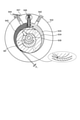
- FIG. 6 is a diagram schematically showing a loss generated in the compressor in a cross-sectional view taken along the line 2B-2B shown in FIG. 2 of the compressor provided in the refrigeration cycle application device according to the present embodiment.
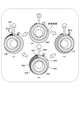
- the figure which shows typically the process of sucking, compressing, and discharging the refrigerant in the cylinder of the compressor which concerns on this embodiment.
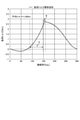
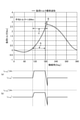
- the figure which shows the load torque in the electric motor of the compressor which concerns on this embodiment, and the timing of the loss which occurs in a compressor.
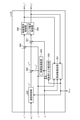
- the figure which shows the structural example of the electric motor drive device which concerns on this embodiment The figure which shows the structural example of the inverter provided in the electric motor drive device which concerns on this embodiment.
- the rectifier circuit 3 includes four diodes D1, D2, D3, and D4.
- the four diodes D1 to D4 are bridge-connected to form a diode bridge circuit.
- the rectifier circuit 3 rectifies the AC voltage supplied from the AC power supply 1 by a diode bridge circuit composed of four diodes D1 to D4.
- one end of the input terminal is connected to the AC power supply 1 via the reactor 2, and the other end of the input terminal is connected to the AC power supply 1. Further, in the rectifier circuit 3, the output terminal is connected to the smoothing capacitor 5.
- the bus voltage detection unit 10 detects the voltage between the DC bus 12a and 12b as the bus voltage Vdc .
- the bus voltage detection unit 10 includes, for example, a voltage dividing circuit that divides the voltage by a resistance connected in series.
- the bus voltage detection unit 10 converts the detected bus voltage Vdc into a voltage suitable for processing by the control device 100 using a voltage dividing circuit, for example, a voltage of 5 V or less, and uses it as a voltage detection signal which is an analog signal.
- Output to the control device 100 The voltage detection signal output from the bus voltage detection unit 10 to the control device 100 is converted from an analog signal to a digital signal by an AD (Analog to Digital) conversion unit (not shown) in the control device 100, and is internally processed by the control device 100. Used for.
- AD Analog to Digital
- FIG. 8 is a diagram showing a configuration example of a control device 100 included in the motor drive device 200 according to the present embodiment.
- the control device 100 includes an operation control unit 102 and an inverter control unit 110.
- FIG. 9 is a diagram showing a configuration example of the voltage command value calculation unit 115 included in the control device 100 according to the present embodiment.
- the voltage command value calculation unit 115 includes a frequency estimation unit 501, a speed control unit 502, a load torque estimation unit 503, a compensation value calculation unit 504, an addition unit 505, a subtraction unit 506, 507, and an excitation current control unit. 508 and a torque current control unit 509 are provided.
- the subtraction unit 506 calculates the difference (i ⁇ * ⁇ i ⁇ ) of the exciting current i ⁇ with respect to the exciting current command value i ⁇ * .
- the subtraction unit 507 calculates the difference (i ⁇ ** ⁇ i ⁇ ) of the torque current i ⁇ with respect to the second torque current command value i ⁇ ** .
- the switching elements 311 to 316 of the inverter main circuit 310 As the switching elements 311 to 316 of the inverter main circuit 310, it is assumed that an IGBT (Insulated Gate Bipolar Transistor), a MOSFET (Metal Oxide Semiconductor Device Transistor), or the like can be performed, but switching can be performed. Any element may be used as long as it is a simple element.
- the switching elements 311 to 316 are MOSFETs, the MOSFET has a parasitic diode due to its structure, so that the same effect can be obtained without connecting the rectifying elements 321 to 326 for circulation in antiparallel. Can be done.
- the compensation value calculation unit 504 accelerates the motor 7 when the load torque T load exceeds the first threshold value, and decelerates the motor 7 when the load torque T load exceeds the second threshold value.
- the torque current compensation value i ⁇ _trq * is calculated as described above.
- the compensation value calculation unit 504 calculates the first threshold value and the second threshold value based on the load torque T load estimated in the control up to the previous time.
- the compensation value calculation unit 504 may use the latest load torque T load as the load torque T load estimated in the control up to the previous time, or may use the average value of the load torque T load for a plurality of times including the latest. May be good.
Landscapes
- Engineering & Computer Science (AREA)
- Power Engineering (AREA)
- Control Of Ac Motors In General (AREA)
- Control Of Motors That Do Not Use Commutators (AREA)
Priority Applications (2)
| Application Number | Priority Date | Filing Date | Title |
|---|---|---|---|
| JP2022542554A JP7361933B2 (ja) | 2020-08-13 | 2020-08-13 | 電動機駆動装置および冷凍サイクル適用機器 |
| PCT/JP2020/030804 WO2022034674A1 (ja) | 2020-08-13 | 2020-08-13 | 電動機駆動装置および冷凍サイクル適用機器 |
Applications Claiming Priority (1)
| Application Number | Priority Date | Filing Date | Title |
|---|---|---|---|
| PCT/JP2020/030804 WO2022034674A1 (ja) | 2020-08-13 | 2020-08-13 | 電動機駆動装置および冷凍サイクル適用機器 |
Publications (1)
| Publication Number | Publication Date |
|---|---|
| WO2022034674A1 true WO2022034674A1 (ja) | 2022-02-17 |
Family
ID=80247102
Family Applications (1)
| Application Number | Title | Priority Date | Filing Date |
|---|---|---|---|
| PCT/JP2020/030804 Ceased WO2022034674A1 (ja) | 2020-08-13 | 2020-08-13 | 電動機駆動装置および冷凍サイクル適用機器 |
Country Status (2)
| Country | Link |
|---|---|
| JP (1) | JP7361933B2 (https=) |
| WO (1) | WO2022034674A1 (https=) |
Cited By (1)
| Publication number | Priority date | Publication date | Assignee | Title |
|---|---|---|---|---|
| WO2024047930A1 (ja) * | 2022-08-29 | 2024-03-07 | パナソニックIpマネジメント株式会社 | 同期機制御装置、圧縮システム、冷凍サイクル装置 |
Citations (2)
| Publication number | Priority date | Publication date | Assignee | Title |
|---|---|---|---|---|
| JP2011151880A (ja) * | 2010-01-19 | 2011-08-04 | Daikin Industries Ltd | 温度異常判断装置 |
| WO2017212794A1 (ja) * | 2016-06-08 | 2017-12-14 | 三菱電機株式会社 | 交流電動機の速度推定装置、交流電動機の駆動装置、冷媒圧縮機および冷凍サイクル装置 |
-
2020
- 2020-08-13 WO PCT/JP2020/030804 patent/WO2022034674A1/ja not_active Ceased
- 2020-08-13 JP JP2022542554A patent/JP7361933B2/ja active Active
Patent Citations (2)
| Publication number | Priority date | Publication date | Assignee | Title |
|---|---|---|---|---|
| JP2011151880A (ja) * | 2010-01-19 | 2011-08-04 | Daikin Industries Ltd | 温度異常判断装置 |
| WO2017212794A1 (ja) * | 2016-06-08 | 2017-12-14 | 三菱電機株式会社 | 交流電動機の速度推定装置、交流電動機の駆動装置、冷媒圧縮機および冷凍サイクル装置 |
Cited By (2)
| Publication number | Priority date | Publication date | Assignee | Title |
|---|---|---|---|---|
| WO2024047930A1 (ja) * | 2022-08-29 | 2024-03-07 | パナソニックIpマネジメント株式会社 | 同期機制御装置、圧縮システム、冷凍サイクル装置 |
| EP4583397A4 (en) * | 2022-08-29 | 2025-11-26 | Panasonic Ip Man Co Ltd | Synchronous machine control device, compression system and refrigeration circuit device |
Also Published As
| Publication number | Publication date |
|---|---|
| JPWO2022034674A1 (https=) | 2022-02-17 |
| JP7361933B2 (ja) | 2023-10-16 |
Similar Documents
| Publication | Publication Date | Title |
|---|---|---|
| JP6723479B1 (ja) | 電動機駆動装置、圧縮機駆動装置および冷凍サイクル装置 | |
| JP6425819B2 (ja) | 電動機駆動装置および冷凍空調装置 | |
| CN107925373B (zh) | 电力变换装置以及热泵装置 | |
| JP2019037135A (ja) | 電力変換装置および空調装置 | |
| JP6410939B2 (ja) | モータ制御装置、圧縮機、及び空気調和機 | |
| JP7361933B2 (ja) | 電動機駆動装置および冷凍サイクル適用機器 | |
| JP2018127956A (ja) | ターボ圧縮機装置および冷凍サイクル装置 | |
| JP6982532B2 (ja) | 冷凍サイクル装置 | |
| US20240405694A1 (en) | Power converting apparatus, motor drive unit, and refrigeration cycle-incorporating device | |
| WO2023073994A1 (ja) | 電動機駆動装置および冷凍サイクル適用機器 | |
| JP7166468B2 (ja) | 電動機駆動装置および冷凍サイクル適用機器 | |
| JP7050951B2 (ja) | 負荷駆動装置、冷凍サイクル装置及び空気調和機 | |
| JP7595807B2 (ja) | モータ駆動装置及び冷凍サイクル装置 | |
| CN112104283A (zh) | 开绕组马达驱动装置以及制冷循环装置 | |
| JP2020139461A (ja) | 電動圧縮機 | |
| WO2023095311A1 (ja) | 電力変換装置、電動機駆動装置及び冷凍サイクル適用機器 | |
| JP6490540B2 (ja) | 回転位置検出装置,空気調和機及び回転位置検出方法 | |
| JP7308949B2 (ja) | 電動機駆動装置及び冷凍サイクル適用機器 | |
| EP3355466B1 (en) | Motor control device, rotary compressor system and motor control method | |
| WO2023105689A1 (ja) | 電力変換装置、電動機駆動装置及び冷凍サイクル適用機器 | |
| WO2020044508A1 (ja) | モータ駆動装置、モータ制御方法および冷凍サイクル装置 | |
| US11971200B2 (en) | Heat pump apparatus with compressor heating control | |
| KR20090049854A (ko) | 공기조화기의 전동기 제어장치 | |
| JP2008271688A (ja) | モータ駆動装置およびこれを用いた冷蔵庫 |
Legal Events
| Date | Code | Title | Description |
|---|---|---|---|
| 121 | Ep: the epo has been informed by wipo that ep was designated in this application |
Ref document number: 20949536 Country of ref document: EP Kind code of ref document: A1 |
|
| ENP | Entry into the national phase |
Ref document number: 2022542554 Country of ref document: JP Kind code of ref document: A |
|
| NENP | Non-entry into the national phase |
Ref country code: DE |
|
| 122 | Ep: pct application non-entry in european phase |
Ref document number: 20949536 Country of ref document: EP Kind code of ref document: A1 |