WO2022034640A1 - 全熱交換素子および換気装置 - Google Patents
全熱交換素子および換気装置 Download PDFInfo
- Publication number
- WO2022034640A1 WO2022034640A1 PCT/JP2020/030615 JP2020030615W WO2022034640A1 WO 2022034640 A1 WO2022034640 A1 WO 2022034640A1 JP 2020030615 W JP2020030615 W JP 2020030615W WO 2022034640 A1 WO2022034640 A1 WO 2022034640A1
- Authority
- WO
- WIPO (PCT)
- Prior art keywords
- flow path
- heat exchange
- total heat
- exchange element
- air flow
- Prior art date
Links
Images


Classifications
-
- F—MECHANICAL ENGINEERING; LIGHTING; HEATING; WEAPONS; BLASTING
- F28—HEAT EXCHANGE IN GENERAL
- F28D—HEAT-EXCHANGE APPARATUS, NOT PROVIDED FOR IN ANOTHER SUBCLASS, IN WHICH THE HEAT-EXCHANGE MEDIA DO NOT COME INTO DIRECT CONTACT
- F28D21/00—Heat-exchange apparatus not covered by any of the groups F28D1/00 - F28D20/00
- F28D21/0015—Heat and mass exchangers, e.g. with permeable walls
-
- F—MECHANICAL ENGINEERING; LIGHTING; HEATING; WEAPONS; BLASTING
- F24—HEATING; RANGES; VENTILATING
- F24F—AIR-CONDITIONING; AIR-HUMIDIFICATION; VENTILATION; USE OF AIR CURRENTS FOR SCREENING
- F24F12/00—Use of energy recovery systems in air conditioning, ventilation or screening
- F24F12/001—Use of energy recovery systems in air conditioning, ventilation or screening with heat-exchange between supplied and exhausted air
- F24F12/006—Use of energy recovery systems in air conditioning, ventilation or screening with heat-exchange between supplied and exhausted air using an air-to-air heat exchanger
-
- F—MECHANICAL ENGINEERING; LIGHTING; HEATING; WEAPONS; BLASTING
- F28—HEAT EXCHANGE IN GENERAL
- F28D—HEAT-EXCHANGE APPARATUS, NOT PROVIDED FOR IN ANOTHER SUBCLASS, IN WHICH THE HEAT-EXCHANGE MEDIA DO NOT COME INTO DIRECT CONTACT
- F28D9/00—Heat-exchange apparatus having stationary plate-like or laminated conduit assemblies for both heat-exchange media, the media being in contact with different sides of a conduit wall
- F28D9/0062—Heat-exchange apparatus having stationary plate-like or laminated conduit assemblies for both heat-exchange media, the media being in contact with different sides of a conduit wall the conduits for one heat-exchange medium being formed by spaced plates with inserted elements
-
- F—MECHANICAL ENGINEERING; LIGHTING; HEATING; WEAPONS; BLASTING
- F28—HEAT EXCHANGE IN GENERAL
- F28D—HEAT-EXCHANGE APPARATUS, NOT PROVIDED FOR IN ANOTHER SUBCLASS, IN WHICH THE HEAT-EXCHANGE MEDIA DO NOT COME INTO DIRECT CONTACT
- F28D9/00—Heat-exchange apparatus having stationary plate-like or laminated conduit assemblies for both heat-exchange media, the media being in contact with different sides of a conduit wall
- F28D9/0025—Heat-exchange apparatus having stationary plate-like or laminated conduit assemblies for both heat-exchange media, the media being in contact with different sides of a conduit wall the conduits being formed by zig-zag bend plates
-
- F—MECHANICAL ENGINEERING; LIGHTING; HEATING; WEAPONS; BLASTING
- F28—HEAT EXCHANGE IN GENERAL
- F28F—DETAILS OF HEAT-EXCHANGE AND HEAT-TRANSFER APPARATUS, OF GENERAL APPLICATION
- F28F3/00—Plate-like or laminated elements; Assemblies of plate-like or laminated elements
- F28F3/02—Elements or assemblies thereof with means for increasing heat-transfer area, e.g. with fins, with recesses, with corrugations
- F28F3/025—Elements or assemblies thereof with means for increasing heat-transfer area, e.g. with fins, with recesses, with corrugations the means being corrugated, plate-like elements
-
- Y—GENERAL TAGGING OF NEW TECHNOLOGICAL DEVELOPMENTS; GENERAL TAGGING OF CROSS-SECTIONAL TECHNOLOGIES SPANNING OVER SEVERAL SECTIONS OF THE IPC; TECHNICAL SUBJECTS COVERED BY FORMER USPC CROSS-REFERENCE ART COLLECTIONS [XRACs] AND DIGESTS
- Y02—TECHNOLOGIES OR APPLICATIONS FOR MITIGATION OR ADAPTATION AGAINST CLIMATE CHANGE
- Y02B—CLIMATE CHANGE MITIGATION TECHNOLOGIES RELATED TO BUILDINGS, e.g. HOUSING, HOUSE APPLIANCES OR RELATED END-USER APPLICATIONS
- Y02B30/00—Energy efficient heating, ventilation or air conditioning [HVAC]
- Y02B30/56—Heat recovery units
Definitions
- the present disclosure relates to a total heat exchange element and a ventilation device that exchange total heat between air streams.
- the total heat exchange type ventilation fan is used for mechanical ventilation at the same time of supply and exhaust. And the total heat recovery through the total heat exchange element are performed at the same time. As a result, the air conditioning energy can be reduced during the period when heating and cooling are required, and the air quality can be kept in a comfortable state.
- Patent Document 1 discloses a total heat exchange element having a partition plate and a spacing plate for maintaining the spacing between the partition plates, and the partition plate and the spacing plate are bonded to each other with an adhesive.
- an adhesive is applied to the tip of a spacing plate having a corrugated cross section, and the partition plates are bonded and integrated to form a unit constituent member, and then the unit constituent member is formed.
- the spacing plate side is manufactured by applying an adhesive to the spacing plate side and stacking it in a plurality of layers so that the extending directions of the tips of the spacing plates are orthogonal to each other among the unit constituent members adjacent to each other in the stacking direction.
- the first layer air flow path and the second layer air flow path orthogonal to the first layer air flow path alternate in the stacking direction of the partition plate by the partition plate and the spacing plate. Is formed in. Then, latent heat and sensible heat are exchanged between the first air flowing through the first layered air flow path and the second air flowing through the second layered air flow path using the partition plate as a medium.
- the present disclosure has been made in view of the above, and obtains a total heat exchange element capable of improving the humidity exchange efficiency as compared with the conventional case while ensuring the strength for maintaining the shape of the air flow path.
- the purpose is.
- the total heat exchange element of the present disclosure has a corrugated shape in which a partition plate and a plurality of tips including concave portions and convex portions are connected by a side wall portion.
- the machined spacing member and the spacing member are laminated so that the extending directions of the plurality of tips intersect between the adjacent spacing members.
- the total heat exchange element has a plurality of flow paths surrounded by a partition plate and a side wall portion between two partition plates adjacent to each other in the stacking direction.
- the plurality of flow paths have a flow path having a shape that is line-symmetrical with respect to a straight line extending in the stacking direction and a flow path having a shape that is not line-symmetrical with respect to the straight line extending in the stacking direction.
- the length of the side wall portion constituting the flow path having a non-line symmetry shape is longer than the length of the side wall portion constituting the flow path having a line symmetry shape.
- the total heat exchange element according to the present disclosure has the effect of being able to improve the humidity exchange efficiency as compared with the conventional case while ensuring the strength for maintaining the shape of the air flow path.
- FIG. 1 A diagram showing an example of the relationship between the pressure loss in the symmetrical trapezoidal flow path and the left-right asymmetrical trapezoidal flow path and the angle between the bottom of the trapezoid and the hypotenuse.
- the figure which shows typically an example of the structure of the ventilation apparatus by Embodiment 1.
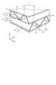
- FIG. 1 is a perspective view schematically showing an example of the configuration of the total heat exchange element according to the first embodiment.
- FIG. 2 is an enlarged perspective view of a part of the configuration of the total heat exchange element according to the first embodiment.
- the directions parallel to the two sides of the square partition plate 2 orthogonal to each other are the X direction and the Y direction, respectively, and the directions orthogonal to both the X direction and the Y direction are Z.
- the relative positional relationship in the Z direction may be expressed using "upper” or "lower”.
- the total heat exchange element 1 has a partition plate 2 and a spacing member 3 that holds the spacing between the partition plates 2.
- the partition plate 2 is a plate-shaped member having a moisture permeability which is a property of passing water vapor but not an air, and a gas shielding property which is a property of separating the supply air flow and the exhaust flow, which will be described later.
- the partition plate 2 has a square shape in one example.
- the space holding member 3 is a member in which a concave portion 31a as a valley portion and a convex portion 31b as a mountain portion are alternately and continuously processed into a corrugated shape.
- the concave portion 31a and the convex portion 31b extend in the X direction or the Y direction.
- the concave portion 31a of the space holding member 3 is adhered to the lower partition plate 2 with an adhesive, and the convex portion 31b is adhered to the upper partition plate 2 with an adhesive.
- the concave portion 31a and the convex portion 31b are referred to as a tip portion 31.
- the tip portion 31 is a portion that comes into contact with the partition plate 2 via an adhesive.
- the surface connecting the adjacent tip portions 31 in the arrangement direction of the plurality of tip portions 31, that is, the surface connecting the bottom portion of the concave portion 31a and the top portion of the convex portion 31b is referred to as a side wall portion 32. That is, the spacing member 3 has a structure in which the tip portion 31 and the tip portion 31 are connected by a side wall portion 32. In the examples of FIGS. 1 and 2, the tip portion 31 and the side wall portion 32 are planar, respectively.
- the dimensions of the spacing member 3 in the XY plane are the same as the dimensions of the partition plate 2.
- the unit constituent member 5 is a member in which the partition plate 2 is attached to and integrated with the interval holding member 3 to which the adhesive is applied to the lower surface of the concave portion 31a which is the tip portion 31.
- the lower surface of the recess 31a of the spacing member 3 is adhered to the upper surface of the partition plate 2 via an adhesive over the extending direction of the recess 31a.
- the unit constituent member 5 becomes a three-dimensional structure having a square bottom surface.
- a corrugated portion of the spacing member 3 is arranged on a pair of sides parallel to each other of the square partition plate 2, and a spacing member 3 is arranged on the other pair of sides parallel to each other.
- the side wall portion 32 of the is arranged.
- the portion of the unit constituent member 5 in which the corrugated portion is exposed to the outside and arranged is referred to as a ventilation surface 51.
- the unit constituent members 5 are laminated in the Z direction so that the ventilation surfaces 51 of the unit constituent members 5 adjacent to each other in the Z direction do not face the same direction.
- the total heat exchange element 1 has a structure in which the unit constituent member 5 rotated by 90 degrees in the XY plane is laminated in the Z direction with respect to the unit constituent member 5 directly underneath.
- an adhesive is applied to the upper surface of the convex portion 31b of the space holding member 3 of the unit constituent member 5 and adhered to the lower surface of the partition plate 2 of the unit constituent member 5 arranged on the upper side.
- a plurality of flow paths surrounded by the partition plate 2 and the side wall portion 32 are formed between the two partition plates 2 adjacent to each other in the Z direction, which is the stacking direction. That is, when paying attention to the pair of partition plates 2 adjacent to each other in the Z direction and the spacing member 3 sandwiched between the pair of partition plates 2, the tip portion 31 and the two side wall portions 32 adjacent to the tip portion 31 A flow path surrounded by the partition plate 2 facing the tip portion 31 and the partition plate 2 is formed. An air flow, which is an air flow, flows through the flow path.
- an in-device air flow path 7 a generic name for a plurality of flow paths formed between two partition plates 2 adjacent to each other in the Z direction.
- the unit constituent member 5 is laminated in the Z direction in a state of being rotated 90 degrees in the XY plane with respect to the unit constituent member 5 directly below.
- the air flow path 7x in the first element which is the air flow path 7 in the element extending in the X direction
- the air flow path 7y in the second element which is the air flow path 7 in the element extending in the Y direction.
- the partition plate 2 when it is not necessary to distinguish between the air flow path 7x in the first element and the air flow path 7y in the second element, it is referred to as the air flow path 7 in the element.
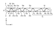
- FIG. 3 is a perspective view showing an example of the appearance of the unit constituent member in the total heat exchange element according to the first embodiment.
- FIG. 4 is a cross-sectional view schematically showing an example of the configuration of the air flow path in the first element of the total heat exchange element according to the first embodiment
- FIG. 5 is a cross-sectional view showing the first embodiment of the total heat exchange element according to the first embodiment.
- It is sectional drawing which shows typically an example of the structure of the air flow path in 2 elements. 4 and 5 show a spacing member 3 sandwiched between a pair of partition plates 2 arranged in the Z direction.
- FIG. 4 shows the ventilation surface 51 perpendicular to the X direction
- FIG. 5 shows the ventilation surface 51 perpendicular to the Y direction.
- the direction in which the tip portions 31 are arranged in the cross section perpendicular to the air flow path 7 in the element is referred to as the left-right direction.
- a symmetrical trapezoidal flow path 71 and a left-right asymmetric trapezoidal flow path 72, 73 are arranged in the left-right direction.
- the space holding member 3 is processed so as to be arranged in. More specifically, the symmetrical trapezoidal shape indicates that the trapezoidal shape is line-symmetrical with respect to a straight line parallel to the stacking direction, that is, the Z direction in the cross section perpendicular to the air flow path 7 in the element. There is.
- the left-right asymmetric trapezoidal shape indicates that the trapezoidal shape is not line-symmetrical with respect to a straight line parallel to the Z direction in a cross section perpendicular to the air flow path 7 in the element.
- the symmetrical trapezoidal flow path 71 corresponds to a flow path having a line symmetry with respect to a straight line extending in the stacking direction, and the left-right asymmetric trapezoidal flow paths 72 and 73 are laminated.
- the space holding member 3 is processed by bending a flat plate-shaped member.
- the ratio of the symmetrical trapezoidal flow path 71 to the left-right asymmetric trapezoidal flow path 72, 73 is the flow path when a predetermined number of unit constituent members 5 are laminated in the Z direction. It is determined in advance by experiment or calculation so that the strength can maintain the shape of 71, 72, 73.
- the ratio of the symmetrical trapezoidal flow path 71 and the left-right asymmetric trapezoidal flow path 72, 73 having the strength to maintain the shape of the flow paths 71, 72, 73 is symmetrical. It can change depending on the angle of the side wall portion 32 with respect to the partition plate 2 in the trapezoidal flow path 71.
- the interval holding member 3 cannot maintain the shape of the flow paths 71, 72, 73 and may be crushed.
- the ratio of the symmetrical trapezoidal shape is predetermined. It is desirable that the value is equal to or higher than the above value.
- two partition plates 2 are arranged in parallel with an interval in the Z direction with the interval holding member 3 interposed therebetween.
- the space surrounded by the two partition plates 2 is the air flow path 7x in the first element or the air flow path 7y in the second element.
- the space-holding member 3 in the cross section perpendicular to the air flow path 7x in the first element, has an equipotenuse-shaped flow path 71x and an equi-legged flow path 71x having the same hypotenuse length. Spacing member so that a hypotenuse of the same length as the hypotenuse of the left-right asymmetric trapezoidal flow path 72x, 73x having a hypotenuse longer than the hypotenuse of the equipodenuse-shaped flow path 71x is formed. 3 is processed.
- the left-right asymmetric trapezoidal flow paths 72x and 73x are arranged so that the longer hypotenuse of the left-right asymmetric trapezoidal flow paths 72x and 73x is arranged toward the isosceles trapezoidal flow path 71x.
- the flow paths 71x, 72x, 73x are formed between the space holding member 3 and the lower partition plate 2, and the flow path 71x is also formed between the space holding member 3 and the upper partition plate 2.
- 72x, 73x are inverted in the vertical direction, respectively, to form flow paths 74x, 75x, 76x.
- the air flow path 7x in the first element has different shapes of the flow paths 71x and 72x due to the space holding member 3 and the two partition plates 2 sandwiching the space holding member 3. , 73x, 74x, 75x, 76x, and the flow paths 71x, 76x, 72x, 74x, 73x, 75x are continuously provided in order.
- the air flow path 7y in the second element is the same as the air flow path 7x in the first element.
- the space holding member 3 has an equipotenuse-shaped flow path 71y having the same hypotenuse length and an isotropic trapezoidal flow. Spacing so that a hypotenuse of the same length as the hypotenuse of the road 71y and an asymmetric trapezoidal flow path 72y, 73y having a hypotenuse longer than the hypotenuse of the isobaric trapezoidal flow path 71y are formed.
- the holding member 3 is processed.
- the left-right asymmetric trapezoidal flow paths 72y and 73y are arranged so that the longer hypotenuse of the left-right asymmetric trapezoidal flow paths 72y and 73y is arranged toward the isosceles trapezoidal flow path 71y.
- the flow paths 71y, 72y, 73y are formed between the space holding member 3 and the lower partition plate 2, and the flow path 71y is also formed between the space holding member 3 and the upper partition plate 2.
- 72y, 73y are inverted in the vertical direction, respectively, to form flow paths 74y, 75y, 76y.
- the air flow path 7y in the second element has different shapes of the flow paths 71y and 72y due to the space holding member 3 and the two partition plates 2 sandwiching the space holding member 3. , 73y, 74y, 75y, 76y, and the flow paths 71y, 76y, 72y, 74y, 73y, 75y are continuously provided in order.
- the shapes of the flow paths 74x, 75x, 76x are inevitable if the shapes of the flow paths 71x, 72x, 73x are determined. Is decided. Therefore, here, the shapes of the flow paths 71x, 72x, and 73x will be described.
- the space holding member 3 is processed so that the flow path 71x has a symmetrical trapezoidal shape with the same length of the two hypotenuses, that is, an isosceles trapezoidal shape.
- the lower bottom is composed of the partition plate 2 instead of the space holding member 3.
- the upper bottom of the isosceles trapezoidal shape corresponds to the convex portion 31b of the spacing member 3, and the convex portion 31b is adhered to the upper partition plate 2 with the adhesive 4.
- the angle formed by the lower partition plate 2 and the side wall portion 32 which is the hypotenuse on the left side constituting the flow path 71x is ⁇ 1, and the side wall portion 32 which is the hypotenuse on the right side constituting the lower partition plate 2 and the flow path 71x.
- the flow path 71x has a symmetrical isosceles trapezoidal shape in which the lengths of the two hypotenuses are equal.
- the lower part of the hypotenuse on the right side constituting the flow path 71x corresponds to the recess 31a of the spacing member 3, and the recess 31a is adhered to the lower partition plate 2 with the adhesive 4.
- the concave portion 31a is adhered by the same length as the adhesive portion of the convex portion 31b.
- a flow path 72x is provided on the lower side of the space holding member 3 with the adhesive 4 which is an adhesive portion interposed therebetween.
- the hypotenuse of the flow path 72x is spaced so that the hypotenuse on the left side is longer than the hypotenuse on the left side of the flow path 71x, and the hypotenuse on the right side has a left-right asymmetric trapezoidal shape having approximately the same length as the hypotenuse of the flow path 71x. It is configured by processing the holding member 3. However, the lower bottom is composed of the partition plate 2 instead of the space holding member 3. The convex portion 31b of the space holding member 3 located on the upper bottom of the trapezoidal shape is adhered to the upper partition plate 2 with the adhesive 4.
- the flow path 72x has a left-right asymmetric trapezoidal shape in which the lengths of the two hypotenuses are different.
- the lower part of the hypotenuse on the right side constituting the flow path 72x corresponds to the recess 31a of the spacing member 3, and the recess 31a is adhered to the lower partition plate 2 with the adhesive 4.
- the concave portion 31a is adhered by the same length as the adhesive portion of the convex portion 31b.
- a flow path 73x is provided on the lower side of the space holding member 3 with the adhesive 4 which is an adhesive portion interposed therebetween.
- the flow path 73x has a left-right asymmetric trapezoidal shape in which the hypotenuse on the left side is approximately the same length as the hypotenuse on the left side of the flow path 71x, and the hypotenuse on the right side is longer than the hypotenuse on the right side of the flow path 71x. It is configured by processing the space holding member 3 so as to be. However, the lower bottom is composed of the partition plate 2 instead of the space holding member 3. The convex portion 31b of the space holding member 3 located on the upper bottom of the trapezoidal shape is adhered to the upper partition plate 2 with the adhesive 4.
- the flow path 73x has a left-right asymmetric trapezoidal shape in which the lengths of the two hypotenuses are different.
- the left-right asymmetric trapezoidal shape of the flow path 72x becomes almost the same shape as the left-right asymmetrical trapezoidal shape of the flow path 73x when inverted in the left-right direction. Further, when the flow path 71x is inverted in the vertical direction, the shape is equivalent to the flow path 74x, when the flow path 72x is inverted in the vertical direction, the shape is equivalent to the flow path 75x, and when the flow path 73x is inverted in the vertical direction, the shape is equivalent to the flow path 76x. It becomes a shape.
- the structures of the flow paths 71y, 72y, 73y, 74y, 75y, and 76y constituting the air flow path 7y in the second element are the flow paths 71x, 72x, 73x constituting the air flow path 7x in the first element.
- 74x, 75x, 76x has the same structure, so the description thereof will be omitted.
- the isosceles trapezoidal flow path 71x and the left-right asymmetrical platform are the units of repetition. Therefore, a unit in which three trapezoidal flow paths are arranged in the left-right direction is used as a repeating unit.
- the space holding member has a structure processed so that isosceles trapezoidal flow paths that are turned upside down are alternately and repeatedly arranged in the left-right direction.
- the repeating unit in the total heat exchange element 1 of the first embodiment includes left-right asymmetric trapezoidal flow paths 72x and 73x having a hypotenuse longer than the hypotenuse of the left-right symmetrical trapezoidal flow path 71x. Therefore, the length of the repeating unit in the left-right direction becomes longer as compared with the case where the three trapezoidal flow paths in the conventional total heat exchange element are repeatedly arranged. As a result, when the spacing member 3 is adhered to the partition plate 2, the number of repeating units included in the partition plate 2 is smaller in the case of the first embodiment than in the conventional case.
- the number of the bonded portions to which the partition plate 2 and the space holding member 3 are bonded by the adhesive 4 is smaller than in the conventional case.
- the moisture permeability is poor due to the presence of the adhesive 4, and the humidity exchange efficiency is low.
- the number of bonded portions is smaller than in the conventional case, so that the humidity is exchanged. Efficiency can be improved.
- the isosceles trapezoidal flow path 71x is included in a predetermined ratio or more, and the position of the isosceles trapezoidal flow path 71x is periodically arranged, the air inside the element. It is possible to form the flow path 7 and maintain the strength for maintaining the shape.
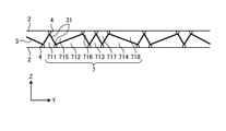
- FIG. 6 is a cross-sectional view schematically showing another example of the configuration of the air flow path of the total heat exchange element according to the first embodiment.
- the same components as those in FIG. 4 are designated by the same reference numerals, and in the example of FIG. 6, the air flow path 7 in the element has a triangular cross-sectional shape of 711,712,713,714.
- FIG. 7 is a cross-sectional view schematically showing another example of the configuration of the air flow path of the total heat exchange element according to the first embodiment.
- the same components as those in FIG. 4 are designated by the same reference numerals, and the description thereof is omitted.
- the tip portions 31 of the upper base and the lower base of FIGS. 4 and 5 are configured by a curve. Therefore, in FIG. 4, the flow paths 71x, 72x, 73x, 74x, 75x, and 76x are trapezoidal, but in FIG. 7, the corners are curved and have a rounded triangular shape. .. Also in this case, the tip portion 31 formed of a curved line is adhered to the partition plate 2 by the adhesive 4.
- Pressure drop is basically related to the wind speed through which the air passes through the flow path or the shape or size of the cross section of the flow path, that is, the equivalent diameter.
- the equivalent diameter is a representative length indicating how much the diameter of the flow path cross section is equivalent to the set of circular tubes.
- FIG. 8 is a diagram showing an example of the relationship between the pressure loss in the symmetrical trapezoidal flow path and the left-right asymmetric trapezoidal flow path and the angle formed by the lower bottom of the trapezoid and the hypotenuse.
- the symmetrical trapezoidal flow path is, for example, a flow path having the same length of two hypotenuses and having ⁇ 1 ⁇ 2, as in the flow paths 71x and 74x in FIG.
- the left-right asymmetric trapezoidal flow path has two different hypotenuse lengths, such as the flow path 72x, 73x, 75x, 76x in FIG. 4, and ⁇ 3 ⁇ ⁇ 4 or ⁇ 5 ⁇ ⁇ 6.
- the horizontal axis is the angle ⁇ [°] between the lower bottom of the flow path and the hypotenuse
- the vertical axis is the pressure loss [Pa] in each flow path.
- the pressure loss is low in the range where ⁇ is larger than 30 ° and 90 ° or less. Further, it can be seen that in the range where ⁇ is 72 ° or less, the pressure loss is lower in the asymmetric trapezoidal flow path than in the symmetrical trapezoidal flow path. That is, the pressure loss in the air flow path of the total heat exchange element 1 can be reduced by including the asymmetrical flow path in the air flow path. Further, in order to reduce the pressure loss, it is desirable that the angle ⁇ between the lower bottom of the trapezoidal flow path and the hypotenuse is larger than 30 ° and 72 ° or less. It should be noted that the same applies whether the shape of the flow path is triangular as shown in FIG.
- the air flow path 7 in the element which includes a flow path having a shape that is line-symmetrical with respect to a straight line parallel to the Z direction and a flow path having a shape that is not line-symmetrical with respect to a straight line parallel to the Z direction. Can be said.
- FIG. 9 is a diagram schematically showing an example of the configuration of the ventilation device according to the first embodiment.
- the ventilation device 100 includes the above-mentioned total heat exchange element 1.
- the ventilation device 100 shown in FIG. 9 is installed in a house or the like and is used as a heat exchange type ventilation device that exchanges heat between indoor air and outdoor air.
- the air supply flow path 131 which is the first air flow path for supplying the outdoor air into the room, and the indoor air are exhausted to the outside. It has an exhaust flow path 132, which is a second air flow path for the purpose, inside.
- the total heat exchange element 1 is arranged in the middle of the supply air flow path 131 and the exhaust flow path 132. Therefore, a part of the air supply flow path 131 includes an air flow path 7x in the first element of the total heat exchange element 1, and a part of the exhaust flow path 132 is a second element of the total heat exchange element 1.
- the inner air flow path 7y is included.
- the ventilation device 100 is provided in the air supply flow path 131 to generate an air flow from the outside to the room, and is provided in the exhaust flow path 132 to generate an air flow from the room to the outside.
- the exhaust blower 134 is provided.
- the air supply blower 133 and the exhaust blower 134 are activated.
- cold and dry outdoor air is passed through the air flow path 7x in the first element as the first air flow 120, which is the air supply
- the warm and humid indoor air is the exhaust flow. It is passed through the air flow path 7y in the second element as the second air flow 130.
- Each air flow of the supply air flow and the exhaust flow that is, two types of air flow flows across the partition plate 2. At this time, heat is transferred between each air flow through the partition plate 2, and water vapor permeates through the partition plate 2, so that heat exchange of sensible heat and latent heat is performed between the supply air flow and the exhaust flow.
- the air supply is warmed and humidified and supplied to the room, and the exhaust flow is cooled and dehumidified and discharged to the outside. Therefore, by ventilating with the ventilation device 100, it is possible to suppress changes in the indoor air temperature and humidity to ventilate the air between the outdoor and the indoor.
- the air flow path 7 in the element is a symmetrical flow path 71 having the same length of two hypotenuses, and one of the two hypotenuses is symmetrical. It is formed by left-right asymmetrical flow paths 72 and 73 that are longer than the hypotenuse of the shape flow path 71. Therefore, the symmetrical flow path 71 can secure the strength in the stacking direction, and the left-right asymmetrical flow paths 72 and 73 reduce the number of bonding portions between the partition plate 2 and the spacing member 3, resulting in total heat.
- the humidity exchange efficiency of the exchange element 1 can be improved and the total heat exchange efficiency can be improved.
- the strength of the total heat exchange element 1 becomes uniform as a whole, and the strength of the total heat exchange element 1 is ensured. can do. Further, by setting the angle ⁇ between the side wall portion 32 of the spacing member 3 and the partition plate 2 to be greater than 30 ° and 72 ° or less, in addition to the above effects, the pressure loss of the air flow path 7 in the element can be reduced. Can be done.
- the configuration shown in the above embodiment is an example, and can be combined with another known technique, or a part of the configuration may be omitted or changed without departing from the gist. It is possible.
Abstract
全熱交換素子は、仕切板(2)と、複数の尖端部の間が側壁部(32)によって接続され、波型形状に加工された間隔保持部材(3)と、が、隣接する間隔保持部材(3)間で複数の尖端部の延在方向が交差するように積層される。全熱交換素子は、積層方向に隣接する2つの仕切板(2)の間に、仕切板(2)と側壁部(32)とによって囲まれる複数の流路(71x,72x,73x,74x,75x,76x)を有する。複数の流路(71x,72x,73x,74x,75x,76x)は、積層方向に延在する直線に対して線対称な形状の流路(71x,74x)と、積層方向に延在する直線に対して線対称でない形状の流路(72x,73x,75x,76x)と、を有する。線対称でない形状の流路(72x,73x,75x,76x)を構成する側壁部(32)の長さは、線対称な形状の流路(71x,74x)を構成する側壁部(32)の長さよりも長い。
Description
本開示は、空気流同士の全熱交換を行わせる全熱交換素子および換気装置に関する。
建物の室内に人が在室している場合には、人体由来、建材由来等による空気を汚染する物質が放散される。このため換気扇等による室内外の空気の置換は人の健康および快適性を確保する上で必須であるが、冷暖房が必要な期間では、室内の空気質に加えて空調機等による温熱環境の確保も重要となる。換気による室内空気質の確保と、空調による温調または除加湿器による調湿と、によって室内の熱および湿度環境の確保を同時に行うために、全熱交換形換気扇によって、給排気同時の機械換気と、全熱交換素子を通した全熱回収と、が同時に行われる。これによって、冷暖房が必要な期間における空調エネルギを低減し、空気質を快適な状態に保つことができる。
全熱交換形換気扇の性能を決める指標のうち、室内外の空気における顕熱および潜熱を合わせた全熱の交換効率である全熱交換効率があり、この全熱交換効率を向上させることが快適性と省エネルギ性とを両立した換気空調には重要である。特許文献1には、仕切板と、仕切板の間隔を保持する間隔板と、を有し、仕切板と間隔板とが接着剤にて接着された全熱交換素子が開示されている。特許文献1に記載の全熱交換素子は、断面が波型の間隔板の尖端部に接着剤を塗布し、仕切板を貼り合わせて一体化して単位構成部材を形成した後、単位構成部材の間隔板側に接着剤を塗布し、積層方向に隣接する単位構成部材間で間隔板の尖端部の延在方向が直交するように複数層に積み重ねることによって製造される。これによって、全熱交換素子には、仕切板および間隔板によって、第1層状空気流路と、第1層状空気流路に直交する第2層状空気流路と、が仕切板の積層方向に交互に形成される。そして、第1層状空気流路を流れる第1空気と、第2層状空気流路を流れる第2空気との間で仕切板を媒体として潜熱および顕熱が交換される。
特許文献1に記載の全熱交換素子では、第1層状空気流路および第2層状空気流路の形状を維持するための強度が要求され、単位構成部材において間隔板は多数の接着部分で仕切板と接着されなければならない。しかしながら、仕切板と間隔板との接着部分には接着剤が存在し、透湿性能が低下するため、湿度交換効率が低くなってしまう。つまり、接着部分が多いほど全熱交換効率が低下してしまうという問題があった。また、仕切板と間隔板との接着部分を少なくすると、湿度交換効率は向上するが、第1層状空気流路および第2層状空気流路の形状を維持するための強度を確保することができなくなってしまう可能性がある。つまり、熱交換素子の強度を確保しつつ、仕切板と間隔板との接着部分を従来に比して少なくすることができる熱交換素子が求められている。
本開示は、上記に鑑みてなされたものであって、空気流路の形状を維持するための強度を確保しつつ従来に比して湿度交換効率を向上させることができる全熱交換素子を得ることを目的とする。
上述した課題を解決し、目的を達成するために、本開示の全熱交換素子は、仕切板と、凹部および凸部を含む複数の尖端部の間が側壁部によって接続され、波型形状に加工された間隔保持部材と、が、隣接する間隔保持部材間で複数の尖端部の延在方向が交差するように積層される。全熱交換素子は、積層方向に隣接する2つの仕切板の間に、仕切板と側壁部とによって囲まれる複数の流路を有する。複数の流路は、積層方向に延在する直線に対して線対称な形状の流路と、積層方向に延在する直線に対して線対称でない形状の流路と、を有する。線対称でない形状の流路を構成する側壁部の長さは、線対称な形状の流路を構成する側壁部の長さよりも長い。
本開示にかかる全熱交換素子は、空気流路の形状を維持するための強度を確保しつつ従来に比して湿度交換効率を向上させることができるという効果を奏する。
以下に、本開示の実施の形態にかかる全熱交換素子および換気装置を図面に基づいて詳細に説明する。
実施の形態1.
図1は、実施の形態1による全熱交換素子の構成の一例を模式的に示す斜視図である。図2は、実施の形態1による全熱交換素子の構成の一部を拡大した斜視図である。図1および図2に示されるように、正方形状の仕切板2の互いに直交する2つの辺に平行な方向をそれぞれX方向およびY方向とし、X方向およびY方向の両方に直交する方向をZ方向とする。以下では、Z方向の相対的な位置関係は、「上」または「下」を用いて表現されることがある。全熱交換素子1は、仕切板2と、仕切板2の間隔を保持する間隔保持部材3と、を有する。
図1は、実施の形態1による全熱交換素子の構成の一例を模式的に示す斜視図である。図2は、実施の形態1による全熱交換素子の構成の一部を拡大した斜視図である。図1および図2に示されるように、正方形状の仕切板2の互いに直交する2つの辺に平行な方向をそれぞれX方向およびY方向とし、X方向およびY方向の両方に直交する方向をZ方向とする。以下では、Z方向の相対的な位置関係は、「上」または「下」を用いて表現されることがある。全熱交換素子1は、仕切板2と、仕切板2の間隔を保持する間隔保持部材3と、を有する。
仕切板2は、水蒸気を通すが空気を通さない性質である透湿性と、後述する給気流と排気流とを隔絶する性質である気体遮蔽性と、を有する板状部材である。仕切板2は、一例では正方形状である。
間隔保持部材3は、谷部となる凹部31aと、山部となる凸部31bと、が交互に連続した波型状に加工された部材である。凹部31aおよび凸部31bは、X方向またはY方向に延在している。間隔保持部材3の凹部31aは、下側の仕切板2と接着剤によって接着され、凸部31bは、上側の仕切板2と接着剤によって接着される。以下では、間隔保持部材3の凹部31aおよび凸部31bを区別する必要がない場合には、凹部31aおよび凸部31bは、尖端部31と称される。尖端部31は、仕切板2と接着剤を介して接触する部分である。複数の尖端部31の配列方向において隣接する尖端部31間を結ぶ面、すなわち凹部31aの底部と凸部31bの頂部との間を結ぶ面は、側壁部32と称される。つまり、間隔保持部材3は、尖端部31と尖端部31との間が側壁部32で接続された構造を有する。図1および図2の例では、尖端部31および側壁部32は、それぞれ平面状である。XY面内における間隔保持部材3の寸法は、仕切板2の寸法と同じである。
ここで、尖端部31である凹部31aの下面に接着剤を塗布した間隔保持部材3に仕切板2を貼り合せて一体化したものを、単位構成部材5と称することにする。単位構成部材5では、間隔保持部材3の凹部31aの下面が、凹部31aの延在方向にわたって仕切板2の上面と接着剤を介して接着される。これによって、単位構成部材5は、底面が正方形状の立体的な構造体となる。単位構成部材5では、正方形状の仕切板2の互いに平行な一対の辺には、間隔保持部材3の波型状の部分が配置され、互いに平行な他の一対の辺には間隔保持部材3の側壁部32が配置される。以下では、単位構成部材5のうち、波型状の部分が外部に露出して配置される部分は、通風面51と称される。
図1および図2に示されるように、全熱交換素子1は、Z方向に隣接する単位構成部材5の通風面51が同じ方向を向かないように、単位構成部材5をZ方向に積層させた構造を有する。すなわち、全熱交換素子1は、直下の単位構成部材5に対して、XY面内において90度回転させた単位構成部材5を、Z方向に積層させた構造を有する。このとき、単位構成部材5の間隔保持部材3の凸部31bの上面に接着剤を塗布し、上側に配置する単位構成部材5の仕切板2の下面と接着させる。
これによって、積層方向であるZ方向に隣接する2つの仕切板2の間に、仕切板2と側壁部32とによって囲まれる複数の流路が形成される。つまり、Z方向に隣接する一対の仕切板2と、一対の仕切板2に挟まれる間隔保持部材3と、に注目したときに、尖端部31と、尖端部31に隣接する2つの側壁部32と、尖端部31に対向する仕切板2と、によって囲まれた流路が形成される。流路には、空気の流れである空気流が流れる。なお、この明細書では、Z方向に隣接する2つの仕切板2の間に形成される複数の流路を総称したものは、素子内空気流路7と称される。
上記したように、全熱交換素子1では、単位構成部材5が直下の単位構成部材5に対してXY面内で90度回転させた状態でZ方向に積層される。この結果、X方向に延在する素子内空気流路7である第1素子内空気流路7xと、Y方向に延在する素子内空気流路7である第2素子内空気流路7yと、が交互に積層されることになる。第1素子内空気流路7xに第1空気流120を流し、第2素子内空気流路7yに第2空気流130を流すことによって、第1空気流120と第2空気流130との間で、仕切板2を媒体として潜熱および顕熱が交換される。なお、以下では、第1素子内空気流路7xと第2素子内空気流路7yとを区別する必要がない場合には、素子内空気流路7と表記する。
次に、間隔保持部材3の形状について詳細に説明する。図3は、実施の形態1による全熱交換素子における単位構成部材の外観の一例を示す斜視図である。図4は、実施の形態1による全熱交換素子の第1素子内空気流路の構成の一例を模式的に示す断面図であり、図5は、実施の形態1による全熱交換素子の第2素子内空気流路の構成の一例を模式的に示す断面図である。図4および図5では、Z方向に配置される一対の仕切板2に挟まれた間隔保持部材3を示している。図4では、X方向に垂直な通風面51が示されており、図5では、Y方向に垂直な通風面51が示されている。なお、以下では、素子内空気流路7に垂直な断面において、尖端部31が配列する方向は左右方向と称される。
図3に示されるように、素子内空気流路7に垂直な断面において、左右対称形の台形状の流路71と、左右非対称形の台形状の流路72,73と、が、左右方向に配列されるように、間隔保持部材3が加工されている。より具体的には、左右対称形の台形状とは、素子内空気流路7に垂直な断面において、積層方向すなわちZ方向に平行な直線に対して線対称な台形状であることを示している。また、左右非対称形の台形状とは、素子内空気流路7に垂直な断面において、Z方向に平行な直線に対して線対称ではない台形状であることを示している。なお、左右対称形の台形状の流路71は、積層方向に延在する直線に対して線対称な形状の流路に対応し、左右非対称形の台形状の流路72,73は、積層方向に延在する直線に対して線対称でない形状の流路に対応する。間隔保持部材3は、一例では、平板状の部材を折り曲げることによって加工される。
左右対称形の台形状の流路71と左右非対称形の台形状の流路72,73との割合は、予め定められた数の単位構成部材5をZ方向に積層させたときに、流路71,72,73の形状を維持することができる強度となるように、予め実験または計算によって求められる。なお、流路71,72,73の形状を維持可能な強度となる左右対称形の台形状の流路71と左右非対称形の台形状の流路72,73との割合は、左右対称形の台形状の流路71における仕切板2に対する側壁部32の角度によって変化し得るものである。左右対称形の台形状の流路71の割合および左右対称形の台形状の流路71における仕切板2に対する側壁部32の角度が、予め定められた条件を満たさない場合には、間隔保持部材3が流路71,72,73の形状を維持することができず、潰れてしまう可能性がある。一例では、左右対称形の台形状の割合が少なすぎると、流路71,72,73の形状を維持することができなくなる可能性があるため、左右対称形の台形状の割合が予め定められた値以上とすることが望ましい。
図4および図5に示されるように、間隔保持部材3を挟んで2つの仕切板2がZ方向に間隔を空けて平行に配置されている。2つの仕切板2によって囲まれた空間が第1素子内空気流路7xまたは第2素子内空気流路7yである。
図4の例では、間隔保持部材3は、第1素子内空気流路7xに垂直な断面において、斜辺が等しい長さの等脚台形状の流路71xと、等脚台形状の流路71xの斜辺と等しい長さの斜辺、および等脚台形状の流路71xの斜辺よりも長い斜辺を有する左右非対称形の台形状の流路72x,73xと、が形成されるように、間隔保持部材3が加工されている。左右非対称形の台形状の流路72x,73xの長い方の斜辺が等脚台形状の流路71xの方に配置されるように、左右非対称形の台形状の流路72x,73xが配置される。
これによって、間隔保持部材3と下側の仕切板2との間に流路71x,72x,73xが形成されるとともに、間隔保持部材3と上側の仕切板2との間にも、流路71x,72x,73xの形状をそれぞれ上下方向に反転させた流路74x,75x,76xが形成される。
この結果、図4に示されるように、間隔保持部材3と、間隔保持部材3を挟む2枚の仕切板2とによって、第1素子内空気流路7xは、形状の異なる流路71x,72x,73x,74x,75x,76xで構成され、流路71x,76x,72x,74x,73x,75xが順番に連続して設けられている。
第2素子内空気流路7yも第1素子内空気流路7xと同様である。図5に示されるように、間隔保持部材3は、第2素子内空気流路7yに垂直な断面において、斜辺が等しい長さの等脚台形状の流路71yと、等脚台形状の流路71yの斜辺と等しい長さの斜辺、および等脚台形状の流路71yの斜辺よりも長い斜辺を有する左右非対称形の台形状の流路72y,73yと、が形成されるように、間隔保持部材3が加工されている。左右非対称形の台形状の流路72y,73yの長い方の斜辺が等脚台形状の流路71yの方に配置されるように、左右非対称形の台形状の流路72y,73yが配置される。
これによって、間隔保持部材3と下側の仕切板2との間に流路71y,72y,73yが形成されるとともに、間隔保持部材3と上側の仕切板2との間にも、流路71y,72y,73yの形状をそれぞれ上下方向に反転させた流路74y,75y,76yが形成される。
この結果、図5に示されるように、間隔保持部材3と、間隔保持部材3を挟む2枚の仕切板2とによって、第2素子内空気流路7yは、形状の異なる流路71y,72y,73y,74y,75y,76yで構成され、流路71y,76y,72y,74y,73y,75yが順番に連続して設けられている。
第1素子内空気流路7xを構成する流路71x,72x,73x,74x,75x,76xのうち、流路74x,75x,76xの形状は流路71x,72x,73xの形状が決まれば必然的に決まる。このため、ここでは、流路71x,72x,73xの形状について説明する。
流路71xは、2つの斜辺の長さが同じである左右対称形の台形状、すなわち等脚台形状となるように間隔保持部材3が加工される。ただし、下底は、間隔保持部材3ではなく、仕切板2によって構成される。等脚台形状の上底は、間隔保持部材3の凸部31bに対応し、凸部31bが上側の仕切板2と接着剤4で接着されている。下側の仕切板2と流路71xを構成する左側の斜辺である側壁部32との成す角度をθ1とし、下側の仕切板2と流路71xを構成する右側の斜辺である側壁部32との成す角度をθ2とすると、θ1≒θ2となっている。つまり、誤差の範囲で、θ1とθ2とは一致している。このように、流路71xは、2つの斜辺の長さが等しい左右対称形の等脚台形状である。
流路71xを構成する右側の斜辺の下部は、間隔保持部材3の凹部31aに対応し、凹部31aが下側の仕切板2と接着剤4で接着されている。一例では、凹部31aは、凸部31bの接着部分と同じ長さだけ接着されている。接着部分である接着剤4を挟んで、間隔保持部材3の下側に流路72xが設けられている。流路72xは、左側の斜辺が流路71xの左側の斜辺よりも長くなっており、右側の斜辺が流路71xの斜辺とほぼ同じ長さである左右非対称形の台形状となるように間隔保持部材3が加工されることによって構成される。ただし、下底は、間隔保持部材3ではなく、仕切板2によって構成される。台形状の上底に位置する間隔保持部材3の凸部31bが上側の仕切板2と接着剤4で接着されている。下側の仕切板2と流路72xを構成する左側の斜辺との成す角度をθ3とし、下側の仕切板2と流路72xを構成する右側の斜辺との成す角度をθ4とすると、θ3<θ1かつθ4≒θ2となっている。このように、流路72xは、2つの斜辺の長さが異なる左右非対称形の台形状である。
流路72xを構成する右側の斜辺の下部は、間隔保持部材3の凹部31aに対応し、凹部31aが下側の仕切板2と接着剤4で接着されている。一例では、凹部31aは、凸部31bの接着部分と同じ長さだけ接着されている。接着部分である接着剤4を挟んで、間隔保持部材3の下側に流路73xが設けられている。流路73xは、左側の斜辺が流路71xの左側の斜辺とほぼ同じ長さになっており、右側の斜辺が流路71xの右側の斜辺よりも長くなっている左右非対称形の台形状となるように間隔保持部材3が加工されることによって構成される。ただし、下底は、間隔保持部材3ではなく、仕切板2によって構成される。台形状の上底に位置する間隔保持部材3の凸部31bが上側の仕切板2と接着剤4で接着されている。下側の仕切板2と流路73xを構成する左側の斜辺との成す角度をθ5とし、下側の仕切板2と流路73xを構成する右側の斜辺との成す角度をθ6とすると、θ6<θ2かつθ5≒θ1となっている。このように、流路73xは、2つの斜辺の長さが異なる左右非対称形の台形状である。
流路72xの左右非対称形の台形状は、左右方向に反転すると流路73xの左右非対称形の台形状とほぼ同等形状になっている。また、流路71xを上下方向に反転すると流路74xと同等形状となり、流路72xを上下方向に反転すると流路75xと同等形状となり、流路73xを上下方向に反転すると流路76xと同等形状となる。なお、第2素子内空気流路7yを構成する各流路71y,72y,73y,74y,75y,76yの構造は、第1素子内空気流路7xを構成する各流路71x,72x,73x,74x,75x,76xの構造と同じであるので、その説明を省略する。
間隔保持部材3と下側の仕切板2との間に形成される台形状の流路に注目すると、実施の形態1の場合では、等脚台形状の流路71xと、左右非対称形の台形状の流路72x,73xと、が繰り返しの単位となる。そこで、3つの台形状の流路を左右方向に配置したものを繰り返しの単位とする。従来の全熱交換素子では、間隔保持部材は、上下を反転させた等脚台形状の流路が左右方向に交互に繰り返し配置されるように加工された構造となる。実施の形態1の全熱交換素子1における繰り返しの単位には、左右対称形の台形状の流路71xの斜辺よりも長い斜辺を有する左右非対称形の台形状の流路72x,73xが含まれるため、従来の全熱交換素子における3つの台形状の流路を繰り返して配置したときと比較して、繰り返しの単位の左右方向の長さが長くなる。この結果、仕切板2に間隔保持部材3を接着させたときに、従来に比して実施の形態1の場合の方が、仕切板2に含まれる繰り返しの単位の数が少なくなる。つまり、実施の形態1の場合の方が、仕切板2と間隔保持部材3とが接着剤4で接着される接着部分の数が従来に比して少なくなる。接着部分では、接着剤4が存在するために透湿性能が悪いため、湿度交換効率が低くなるが、実施の形態1の場合の方が、従来に比して接着部分が少ないので、湿度交換効率を向上させることができる。また、等脚台形状の流路71xを、予め定められた割合以上含ませるようにし、また等脚台形状の流路71xの位置が周期的に配置されるようにしているので、素子内空気流路7を形成し、形状を維持するための強度を維持することが可能となる。
なお、図4および図5の例では、流路71x,72x,73x,74x,75x,76x,71y,72y,73y,74y,75y,76yの形状が台形状である場合を示したが、流路の形状は、台形状に限定されるものではなく、左右対称形状と左右非対称形状とが混在していればよい。図6は、実施の形態1による全熱交換素子の空気流路の構成の他の例を模式的に示す断面図である。なお、図4と同一の構成要素には同一の符号を付して、図6の例では、素子内空気流路7は、断面形状が三角形状である流路711,712,713,714,715,716,717,718を含む。この場合、三角形状の流路711,712,713,714,715,716,717,718を構成する間隔保持部材3の尖端部31が接着剤4によって仕切板2と接着される。このうち、流路711,713,716,717は、左右対称形の二等辺三角形状であり、流路712,714,715,718は、左右非対称形の三角形状である。
図7は、実施の形態1による全熱交換素子の空気流路の構成の他の例を模式的に示す断面図である。なお、図4と同一の構成要素には、同一の符号を付してその説明を省略している。図7の例では、図4および図5の上底および下底の尖端部31を曲線によって構成したものである。このため、図4では、流路71x,72x,73x,74x,75x,76xは台形状であったが、図7では、角部が曲線で構成され、丸みを帯びた三角形状となっている。この場合にも、曲線で構成される尖端部31が接着剤4によって仕切板2と接着される。
次に、第1素子内空気流路7xおよび第2素子内空気流路7yの圧力損失について注目する。全熱交換素子1にとっては、圧力損失が低いほど、性能の優位性がある。圧力損失は基本的に空気が流路を通る風速または流路断面の形状もしくは大きさ、すなわち等価直径と関連している。ここで、等価直径は、流路断面がどのくらいの直径の円管の集合と等価であるかを示す代表長さのことである。
図8は、左右対称形の台形状の流路および左右非対称形の台形状の流路における圧力損失と台形の下底と斜辺とのなす角度との間の関係の一例を示す図である。ここでは、左右対称形の台形状の流路および左右非対称形の台形状の流路における圧力損失と、台形状の流路の斜辺が底辺となす角度θと、の関係を等価直径に換算して計算した結果を示している。左右対称形の台形状の流路は、一例では図4の流路71x,74xのように、2つの斜辺の長さが同じであり、θ1≒θ2である流路である。左右非対称形の台形状の流路は、一例では、図4の流路72x,73x,75x,76xのように、2つの斜辺の長さが異なり、θ3≠θ4またはθ5≠θ6である流路である。図8において、横軸は、流路の下底と斜辺との間の角度θ[°]であり、縦軸は、各流路における圧力損失[Pa]である。
図8に示されるように、θが30°より大きく90°以下の範囲では、圧力損失が低くなっている。さらに、θが72°以下の範囲では、左右対称形の台形状の流路よりも左右非対称形の台形状の流路の方が、圧力損失が低いことがわかる。つまり、左右非対称形の形状の流路を空気流路に含ませることによって、全熱交換素子1の空気流路における圧力損失を低減させることができる。また、圧力損失を低減させるには、台形状の流路の下底と斜辺との間の角度θが30°よりも大きく72°以下であることが望ましいことが分かる。なお、流路の形状が図6のように三角形状であっても、図7のように曲線を含む形状であっても、同様である。すなわち、Z方向に平行な直線に対して線対称な形状の流路と、Z方向に平行な直線に対して線対称でない形状の流路と、を含む素子内空気流路7について、同様のことが言える。
図9は、実施の形態1による換気装置の構成の一例を模式的に示す図である。図9において、換気装置100は、上記した全熱交換素子1を備える。図9に示す換気装置100は、住宅などに設置され、室内の空気と室外の空気との間で熱交換を行う熱交換形換気装置として用いられている。
図9に示されるように、実施の形態1による換気装置100は、室外の空気を室内に給気するための第1空気流路である給気流路131と、室内の空気を室外に排気するための第2空気流路である排気流路132と、を内部に有する。全熱交換素子1は、給気流路131および排気流路132の途中に配置される。このため、給気流路131の一部には、全熱交換素子1の第1素子内空気流路7xが含まれ、排気流路132の一部には、全熱交換素子1の第2素子内空気流路7yが含まれる。
換気装置100は、給気流路131に設けられ、室外から室内に向けた空気の流れを発生させる給気送風機133と、排気流路132に設けられ、室内から室外に向けた空気の流れを発生させる排気送風機134と、を備える。
換気装置100の運転を開始すると、給気送風機133および排気送風機134が作動する。例えば冬場を想定した場合、冷たくて乾燥した室外の空気が給気流である第1空気流120として第1素子内空気流路7xに通され、暖かくて湿気の高い室内の空気が排気流である第2空気流130として第2素子内空気流路7yに通される。給気流および排気流の各空気流、すなわち二種の空気流が仕切板2を隔てて流れる。このとき、仕切板2を介して各空気流の間で熱が伝わり、仕切板2を水蒸気が透過することで、給気流と排気流との間で顕熱および潜熱の熱交換が行われる。この結果、給気流は暖められるとともに加湿されて室内に供給され、排気流は冷やされるとともに減湿されて室外へ排出される。したがって、換気装置100で換気を行うことで、室内の気温および湿度の変化を抑えて室外と室内との空気を換気することができる。
以上のように、実施の形態1による全熱交換素子1では、素子内空気流路7が、2つの斜辺の長さが同じ左右対称形の流路71と、2つの斜辺の一方が左右対称形の流路71の斜辺よりも長い左右非対称形の流路72,73で形成されている。このため、左右対称形の流路71によって積層方向の強度を確保できるとともに、左右非対称形の流路72,73によって仕切板2と間隔保持部材3との接着部分の数が削減され、全熱交換素子1としての湿度交換効率を向上させ全熱交換効率を向上させることができる。
また、左右対称形の流路71と左右非対称形の流路72,73とを順番に繰り返し並べることで全熱交換素子1の強度が全体的に均一となり、全熱交換素子1の強度を確保することができる。さらに、間隔保持部材3の側壁部32と仕切板2との角度θを30°より大きく72°以下にすることで、上記の効果に加え、素子内空気流路7の圧力損失も低減させることができる。
以上の実施の形態に示した構成は、一例を示すものであり、別の公知の技術と組み合わせることも可能であるし、要旨を逸脱しない範囲で、構成の一部を省略、変更することも可能である。
1 全熱交換素子、2 仕切板、3 間隔保持部材、4 接着剤、5 単位構成部材、7 素子内空気流路、7x 第1素子内空気流路、7y 第2素子内空気流路、31 尖端部、31a 凹部、31b 凸部、32 側壁部、51 通風面、71,71x,71y,72,72x,72y,73,73x,73y,74x,74y,75x,75y,76x,76y,711,712,713,714,715,716,717,718 流路、100 換気装置、120 第1空気流、130 第2空気流、131 給気流路、132 排気流路、133 給気送風機、134 排気送風機。
Claims (6)
- 仕切板と、凹部および凸部を含む複数の尖端部の間が側壁部によって接続され、波型形状に加工された間隔保持部材と、が、隣接する前記間隔保持部材間で前記複数の尖端部の延在方向が交差するように積層された全熱交換素子であって、
積層方向に隣接する2つの前記仕切板の間に、前記仕切板と前記側壁部とによって囲まれる複数の流路を有し、
前記複数の流路は、前記積層方向に延在する直線に対して線対称な形状の流路と、前記積層方向に延在する直線に対して線対称でない形状の流路と、を有し、
前記線対称でない形状の流路を構成する前記側壁部の長さは、前記線対称な形状の流路を構成する前記側壁部の長さよりも長いことを特徴とする全熱交換素子。 - 前記複数の流路は、前記線対称な形状の流路と、前記線対称でない形状の流路と、を前記複数の尖端部の配列方向に沿って、規則的に繰り返し並べたことを特徴とする請求項1に記載の全熱交換素子。
- 前記側壁部が前記仕切板と交わる角度は、30°よりも大きく90°以下であることを特徴とする請求項1または2に記載の全熱交換素子。
- 前記側壁部が前記仕切板と交わる角度は、30°よりも大きく72°以下であることを特徴とする請求項1または2に記載の全熱交換素子。
- 前記複数の流路は、台形状、三角形状または角部が曲線で構成される三角形状であることを特徴とする請求項1から4のいずれか1つに記載の全熱交換素子。
- 第1空気流路に第1空気流を流す第1送風機と、
第2空気流路に第2空気流を流す第2送風機と、
前記第1空気流路および前記第2空気流路の途中に配置され、請求項1から5のいずれか1つに記載の全熱交換素子と、
を備えることを特徴とする換気装置。
Priority Applications (4)
| Application Number | Priority Date | Filing Date | Title |
|---|---|---|---|
| PCT/JP2020/030615 WO2022034640A1 (ja) | 2020-08-11 | 2020-08-11 | 全熱交換素子および換気装置 |
| US18/001,891 US20230235916A1 (en) | 2020-08-11 | 2020-08-11 | Total heat exchange element and ventilator |
| JP2022542527A JP7333875B2 (ja) | 2020-08-11 | 2020-08-11 | 全熱交換素子および換気装置 |
| CN202080104187.3A CN116209870A (zh) | 2020-08-11 | 2020-08-11 | 全热交换元件以及换气装置 |
Applications Claiming Priority (1)
| Application Number | Priority Date | Filing Date | Title |
|---|---|---|---|
| PCT/JP2020/030615 WO2022034640A1 (ja) | 2020-08-11 | 2020-08-11 | 全熱交換素子および換気装置 |
Publications (1)
| Publication Number | Publication Date |
|---|---|
| WO2022034640A1 true WO2022034640A1 (ja) | 2022-02-17 |
Family
ID=80247951
Family Applications (1)
| Application Number | Title | Priority Date | Filing Date |
|---|---|---|---|
| PCT/JP2020/030615 WO2022034640A1 (ja) | 2020-08-11 | 2020-08-11 | 全熱交換素子および換気装置 |
Country Status (4)
| Country | Link |
|---|---|
| US (1) | US20230235916A1 (ja) |
| JP (1) | JP7333875B2 (ja) |
| CN (1) | CN116209870A (ja) |
| WO (1) | WO2022034640A1 (ja) |
Cited By (1)
| Publication number | Priority date | Publication date | Assignee | Title |
|---|---|---|---|---|
| WO2024062122A1 (en) * | 2022-09-23 | 2024-03-28 | Velocys Technologies Ltd | Channel assembly |
Families Citing this family (1)
| Publication number | Priority date | Publication date | Assignee | Title |
|---|---|---|---|---|
| FR3105387B1 (fr) * | 2019-12-20 | 2021-11-26 | Liebherr Aerospace Toulouse Sas | Échangeur de chaleur à passages de fluide optimisés |
Citations (6)
| Publication number | Priority date | Publication date | Assignee | Title |
|---|---|---|---|---|
| GB693476A (en) * | 1950-10-24 | 1953-07-01 | Separator Ab | Improvements in or relating to heat exchangers |
| US6164372A (en) * | 1998-09-01 | 2000-12-26 | Ip Compact Ab | Heat exchanger |
| JP2003071237A (ja) * | 2001-09-06 | 2003-03-11 | Daikin Ind Ltd | 冷却用素子及びこれを備えた除湿素子 |
| US20060289152A1 (en) * | 2005-06-23 | 2006-12-28 | Joerg Leuschner | Heat exchange element and heat exchanger produced therewith |
| JP2012141121A (ja) * | 2010-12-16 | 2012-07-26 | Shimizu Corp | 全熱交換素子 |
| JP2019504287A (ja) * | 2015-12-18 | 2019-02-14 | コア エネルギー リカバリー ソリューションズ インコーポレイテッド | エンタルピー交換器 |
-
2020
- 2020-08-11 CN CN202080104187.3A patent/CN116209870A/zh active Pending
- 2020-08-11 JP JP2022542527A patent/JP7333875B2/ja active Active
- 2020-08-11 US US18/001,891 patent/US20230235916A1/en active Pending
- 2020-08-11 WO PCT/JP2020/030615 patent/WO2022034640A1/ja active Application Filing
Patent Citations (6)
| Publication number | Priority date | Publication date | Assignee | Title |
|---|---|---|---|---|
| GB693476A (en) * | 1950-10-24 | 1953-07-01 | Separator Ab | Improvements in or relating to heat exchangers |
| US6164372A (en) * | 1998-09-01 | 2000-12-26 | Ip Compact Ab | Heat exchanger |
| JP2003071237A (ja) * | 2001-09-06 | 2003-03-11 | Daikin Ind Ltd | 冷却用素子及びこれを備えた除湿素子 |
| US20060289152A1 (en) * | 2005-06-23 | 2006-12-28 | Joerg Leuschner | Heat exchange element and heat exchanger produced therewith |
| JP2012141121A (ja) * | 2010-12-16 | 2012-07-26 | Shimizu Corp | 全熱交換素子 |
| JP2019504287A (ja) * | 2015-12-18 | 2019-02-14 | コア エネルギー リカバリー ソリューションズ インコーポレイテッド | エンタルピー交換器 |
Cited By (1)
| Publication number | Priority date | Publication date | Assignee | Title |
|---|---|---|---|---|
| WO2024062122A1 (en) * | 2022-09-23 | 2024-03-28 | Velocys Technologies Ltd | Channel assembly |
Also Published As
| Publication number | Publication date |
|---|---|
| US20230235916A1 (en) | 2023-07-27 |
| JPWO2022034640A1 (ja) | 2022-02-17 |
| JP7333875B2 (ja) | 2023-08-25 |
| CN116209870A (zh) | 2023-06-02 |
Similar Documents
| Publication | Publication Date | Title |
|---|---|---|
| WO2022034640A1 (ja) | 全熱交換素子および換気装置 | |
| US20110209858A1 (en) | Indirect Evaporative Cooling Apparatus | |
| US8590606B2 (en) | Heat exchange element and manufacturing method thereof, heat exchanger, and heat exchange ventilator | |
| BR112014012144B1 (pt) | matriz de troca de calor | |
| JP5987854B2 (ja) | 熱交換素子及び熱交換器 | |
| JP6078668B1 (ja) | 間接気化式空調装置 | |
| JPH08313186A (ja) | 熱交換器 | |
| JP6518176B2 (ja) | 調湿システム | |
| WO2020226047A1 (ja) | 全熱交換素子 | |
| JP2003139481A (ja) | 熱交換器及び熱交換器の製造方法 | |
| KR20100059140A (ko) | 환기덕트용 전열교환기 소자 | |
| JPH09287794A (ja) | 熱交換器及び熱交換器の製造方法並びに熱交換換気装置 | |
| JP4269843B2 (ja) | 冷却吸着素子 | |
| JPS602888A (ja) | 熱交換素子 | |
| JP6833106B2 (ja) | 全熱交換素子および全熱交換器 | |
| JP3649203B2 (ja) | 調湿装置 | |
| JP6815516B2 (ja) | 全熱交換素子および熱交換換気装置 | |
| JPS6238155Y2 (ja) | ||
| JP7126617B2 (ja) | 熱交換素子および熱交換換気装置 | |
| WO2022130470A1 (ja) | 全熱交換素子および全熱交換換気装置 | |
| JP6801735B2 (ja) | 熱交換器 | |
| JP4021048B2 (ja) | 熱交換素子 | |
| JP2003144834A (ja) | 冷却吸着素子 | |
| JP2018169056A (ja) | 空調システム | |
| JP4289071B2 (ja) | 熱交換素子 |
Legal Events
| Date | Code | Title | Description |
|---|---|---|---|
| 121 | Ep: the epo has been informed by wipo that ep was designated in this application |
Ref document number: 20949502 Country of ref document: EP Kind code of ref document: A1 |
|
| ENP | Entry into the national phase |
Ref document number: 2022542527 Country of ref document: JP Kind code of ref document: A |
|
| NENP | Non-entry into the national phase |
Ref country code: DE |
|
| 122 | Ep: pct application non-entry in european phase |
Ref document number: 20949502 Country of ref document: EP Kind code of ref document: A1 |