WO2022030047A1 - 遠隔操作装置 - Google Patents
遠隔操作装置 Download PDFInfo
- Publication number
- WO2022030047A1 WO2022030047A1 PCT/JP2021/015911 JP2021015911W WO2022030047A1 WO 2022030047 A1 WO2022030047 A1 WO 2022030047A1 JP 2021015911 W JP2021015911 W JP 2021015911W WO 2022030047 A1 WO2022030047 A1 WO 2022030047A1
- Authority
- WO
- WIPO (PCT)
- Prior art keywords
- image
- actual machine
- information
- movable range
- unit
- Prior art date
Links
- 238000004364 calculation method Methods 0.000 claims description 24
- 238000006243 chemical reaction Methods 0.000 claims description 22
- 238000003384 imaging method Methods 0.000 claims description 14
- 238000003825 pressing Methods 0.000 claims description 9
- 238000012800 visualization Methods 0.000 claims description 2
- 238000010586 diagram Methods 0.000 description 105
- 238000013519 translation Methods 0.000 description 48
- 230000007246 mechanism Effects 0.000 description 27
- 239000012636 effector Substances 0.000 description 19
- 239000013598 vector Substances 0.000 description 18
- 238000012937 correction Methods 0.000 description 13
- 230000000694 effects Effects 0.000 description 10
- 230000006870 function Effects 0.000 description 8
- 238000000034 method Methods 0.000 description 6
- 230000008859 change Effects 0.000 description 3
- 230000006399 behavior Effects 0.000 description 2
- 238000012545 processing Methods 0.000 description 2
- 230000009471 action Effects 0.000 description 1
- 238000004891 communication Methods 0.000 description 1
- 238000011478 gradient descent method Methods 0.000 description 1
- 238000010801 machine learning Methods 0.000 description 1
- 238000013507 mapping Methods 0.000 description 1
- 239000003550 marker Substances 0.000 description 1
- 238000005457 optimization Methods 0.000 description 1
- 230000009466 transformation Effects 0.000 description 1
Images


Classifications
-
- B—PERFORMING OPERATIONS; TRANSPORTING
- B25—HAND TOOLS; PORTABLE POWER-DRIVEN TOOLS; MANIPULATORS
- B25J—MANIPULATORS; CHAMBERS PROVIDED WITH MANIPULATION DEVICES
- B25J9/00—Programme-controlled manipulators
- B25J9/16—Programme controls
- B25J9/1679—Programme controls characterised by the tasks executed
- B25J9/1689—Teleoperation
-
- H—ELECTRICITY
- H04—ELECTRIC COMMUNICATION TECHNIQUE
- H04N—PICTORIAL COMMUNICATION, e.g. TELEVISION
- H04N23/00—Cameras or camera modules comprising electronic image sensors; Control thereof
- H04N23/60—Control of cameras or camera modules
- H04N23/66—Remote control of cameras or camera parts, e.g. by remote control devices
-
- G—PHYSICS
- G05—CONTROLLING; REGULATING
- G05B—CONTROL OR REGULATING SYSTEMS IN GENERAL; FUNCTIONAL ELEMENTS OF SUCH SYSTEMS; MONITORING OR TESTING ARRANGEMENTS FOR SUCH SYSTEMS OR ELEMENTS
- G05B19/00—Programme-control systems
- G05B19/02—Programme-control systems electric
- G05B19/18—Numerical control [NC], i.e. automatically operating machines, in particular machine tools, e.g. in a manufacturing environment, so as to execute positioning, movement or co-ordinated operations by means of programme data in numerical form
- G05B19/409—Numerical control [NC], i.e. automatically operating machines, in particular machine tools, e.g. in a manufacturing environment, so as to execute positioning, movement or co-ordinated operations by means of programme data in numerical form characterised by using manual input [MDI] or by using control panel, e.g. controlling functions with the panel; characterised by control panel details, by setting parameters
-
- G—PHYSICS
- G06—COMPUTING; CALCULATING OR COUNTING
- G06T—IMAGE DATA PROCESSING OR GENERATION, IN GENERAL
- G06T11/00—2D [Two Dimensional] image generation
-
- G—PHYSICS
- G05—CONTROLLING; REGULATING
- G05B—CONTROL OR REGULATING SYSTEMS IN GENERAL; FUNCTIONAL ELEMENTS OF SUCH SYSTEMS; MONITORING OR TESTING ARRANGEMENTS FOR SUCH SYSTEMS OR ELEMENTS
- G05B2219/00—Program-control systems
- G05B2219/30—Nc systems
- G05B2219/35—Nc in input of data, input till input file format
- G05B2219/35438—Joystick
-
- G—PHYSICS
- G05—CONTROLLING; REGULATING
- G05B—CONTROL OR REGULATING SYSTEMS IN GENERAL; FUNCTIONAL ELEMENTS OF SUCH SYSTEMS; MONITORING OR TESTING ARRANGEMENTS FOR SUCH SYSTEMS OR ELEMENTS
- G05B2219/00—Program-control systems
- G05B2219/30—Nc systems
- G05B2219/35—Nc in input of data, input till input file format
- G05B2219/35506—Camera images overlayed with graphics, model
-
- G—PHYSICS
- G05—CONTROLLING; REGULATING
- G05B—CONTROL OR REGULATING SYSTEMS IN GENERAL; FUNCTIONAL ELEMENTS OF SUCH SYSTEMS; MONITORING OR TESTING ARRANGEMENTS FOR SUCH SYSTEMS OR ELEMENTS
- G05B2219/00—Program-control systems
- G05B2219/30—Nc systems
- G05B2219/36—Nc in input of data, input key till input tape
- G05B2219/36447—Project light on path to be followed, keep also distance constant
-
- G—PHYSICS
- G05—CONTROLLING; REGULATING
- G05B—CONTROL OR REGULATING SYSTEMS IN GENERAL; FUNCTIONAL ELEMENTS OF SUCH SYSTEMS; MONITORING OR TESTING ARRANGEMENTS FOR SUCH SYSTEMS OR ELEMENTS
- G05B2219/00—Program-control systems
- G05B2219/30—Nc systems
- G05B2219/37—Measurements
- G05B2219/37571—Camera detecting reflected light from laser
-
- G—PHYSICS
- G05—CONTROLLING; REGULATING
- G05B—CONTROL OR REGULATING SYSTEMS IN GENERAL; FUNCTIONAL ELEMENTS OF SUCH SYSTEMS; MONITORING OR TESTING ARRANGEMENTS FOR SUCH SYSTEMS OR ELEMENTS
- G05B2219/00—Program-control systems
- G05B2219/30—Nc systems
- G05B2219/39—Robotics, robotics to robotics hand
- G05B2219/39014—Match virtual world with real world
-
- G—PHYSICS
- G05—CONTROLLING; REGULATING
- G05B—CONTROL OR REGULATING SYSTEMS IN GENERAL; FUNCTIONAL ELEMENTS OF SUCH SYSTEMS; MONITORING OR TESTING ARRANGEMENTS FOR SUCH SYSTEMS OR ELEMENTS
- G05B2219/00—Program-control systems
- G05B2219/30—Nc systems
- G05B2219/39—Robotics, robotics to robotics hand
- G05B2219/39451—Augmented reality for robot programming
-
- G—PHYSICS
- G05—CONTROLLING; REGULATING
- G05B—CONTROL OR REGULATING SYSTEMS IN GENERAL; FUNCTIONAL ELEMENTS OF SUCH SYSTEMS; MONITORING OR TESTING ARRANGEMENTS FOR SUCH SYSTEMS OR ELEMENTS
- G05B2219/00—Program-control systems
- G05B2219/30—Nc systems
- G05B2219/40—Robotics, robotics mapping to robotics vision
- G05B2219/40131—Virtual reality control, programming of manipulator
-
- G—PHYSICS
- G05—CONTROLLING; REGULATING
- G05B—CONTROL OR REGULATING SYSTEMS IN GENERAL; FUNCTIONAL ELEMENTS OF SUCH SYSTEMS; MONITORING OR TESTING ARRANGEMENTS FOR SUCH SYSTEMS OR ELEMENTS
- G05B2219/00—Program-control systems
- G05B2219/30—Nc systems
- G05B2219/40—Robotics, robotics mapping to robotics vision
- G05B2219/40168—Simulated display of remote site, driven by operator interaction
-
- G—PHYSICS
- G05—CONTROLLING; REGULATING
- G05B—CONTROL OR REGULATING SYSTEMS IN GENERAL; FUNCTIONAL ELEMENTS OF SUCH SYSTEMS; MONITORING OR TESTING ARRANGEMENTS FOR SUCH SYSTEMS OR ELEMENTS
- G05B2219/00—Program-control systems
- G05B2219/30—Nc systems
- G05B2219/40—Robotics, robotics mapping to robotics vision
- G05B2219/40382—Limit allowable area where robot can be teached
-
- G—PHYSICS
- G05—CONTROLLING; REGULATING
- G05B—CONTROL OR REGULATING SYSTEMS IN GENERAL; FUNCTIONAL ELEMENTS OF SUCH SYSTEMS; MONITORING OR TESTING ARRANGEMENTS FOR SUCH SYSTEMS OR ELEMENTS
- G05B2219/00—Program-control systems
- G05B2219/30—Nc systems
- G05B2219/40—Robotics, robotics mapping to robotics vision
- G05B2219/40478—Graphic display of work area of robot, forbidden, permitted zone
-
- G—PHYSICS
- G05—CONTROLLING; REGULATING
- G05B—CONTROL OR REGULATING SYSTEMS IN GENERAL; FUNCTIONAL ELEMENTS OF SUCH SYSTEMS; MONITORING OR TESTING ARRANGEMENTS FOR SUCH SYSTEMS OR ELEMENTS
- G05B2219/00—Program-control systems
- G05B2219/30—Nc systems
- G05B2219/40—Robotics, robotics mapping to robotics vision
- G05B2219/40617—Agile eye, control position of camera, active vision, pan-tilt camera, follow object
Definitions
- This disclosure relates to a remote control device in which an operator remotely controls an actual machine.
- the behavior of the actual machine predicted by the operator differs from the behavior of the actual actual machine, so that it becomes difficult to predict the motion of the actual machine and the work efficiency deteriorates.
- Patent Document 1 discloses a user interface of a very dexterous system.
- the system sets the range of motion of the actual machine in order to facilitate the prediction of the motion of the actual machine.
- An object of the present disclosure is to provide a remote control device that improves work efficiency by setting a movable range of an actual machine and presenting the set movable range to an operator.
- the remote control device is a remote control device in which an operator remotely operates an actual machine, and is a limiting unit that sets a movable range of the actual machine based on the restriction information from the operator.
- An operation unit that generates first command information, which is input information for operating the actual machine, based on the operation information from the operator and the movable range, and the actual machine that is visualized. It is provided with an image display unit that displays a machine image and a movable information image in which the movable range corresponding to the actual machine is visualized.
- the remote control device can improve the work efficiency as compared with the conventional case by setting the movable range of the actual machine and presenting the set movable range to the operator.
- FIG. It is a block diagram which shows an example of the structure of the remote control device in Embodiment 1.
- FIG. It is a schematic diagram which shows an example of the structure including the operation part in Embodiment 1.
- FIG. It is a schematic diagram which shows an example of the operation part in Embodiment 1.
- FIG. It is a schematic diagram which shows an example of the structure including the actual machine in Embodiment 1.
- FIG. It is a schematic diagram which shows an example of the limitation part at the time of setting the movable range in the 1st mode in Embodiment 1.
- FIG. It is a schematic diagram which shows an example of the image in the image display part when the movable range is set in the 1st mode in Embodiment 1.
- FIG. 1 It is a schematic diagram which shows an example of the limitation part at the time of setting the movable range in the 2nd mode in Embodiment 1.
- FIG. 2nd mode it is a schematic diagram which shows an example of the image in the image display part when the movable range is set in the 2nd mode in Embodiment 1.
- FIG. 2nd mode it is a schematic diagram which shows an example of the limitation part at the time of setting the movable range in the 3rd mode in Embodiment 1.
- FIG. It is a schematic diagram which shows an example of the image in the image display part when the movable range is set in the 3rd mode in Embodiment 1.
- FIG. 1 It is a schematic diagram which shows an example of the image in the image display part when the movable range is set in the 4th mode in Embodiment 1.
- FIG. It is a schematic diagram which shows an example of the structure of the model generation part in the case of setting the movable range in the 5th mode in Embodiment 1.
- FIG. It is a schematic diagram which shows an example of the operation part in the case of setting the movable range in the 5th mode in Embodiment 1.
- FIG. It is a schematic diagram which shows an example of the image in the image display part when the movable range is set in the 5th mode in Embodiment 1.
- FIG. It is a schematic diagram which shows an example of another image in the image display part when the movable range is set in the 5th mode in Embodiment 1.
- FIG. It is a block diagram which shows an example of the structure of the remote control device in Embodiment 2. It is a schematic diagram which shows an example of the structure including the actual machine in Embodiment 2. It is a schematic diagram which shows an example of another configuration including the actual machine in Embodiment 2. It is a schematic diagram which shows an example of the image in the image display part in Embodiment 2. It is a schematic diagram which shows an example of another image in the image display part in Embodiment 2.
- FIG. It is a block diagram which shows an example of the structure of the remote control device in Embodiment 3.
- Embodiment 7 It is a schematic diagram which shows an example of the structure including the actual machine in Embodiment 7. It is a schematic diagram which shows an example of the image in the image display part in Embodiment 7. It is a schematic diagram which shows the relationship between the movable range and the motion locus of an end effector in Embodiment 7. It is a flowchart which shows an example of the operation of the remote control device in Embodiment 7.
- the xyz orthogonal coordinate system is defined in the direction in which the x-axis translation mechanism 31, the y-axis translation mechanism 32, and the z-axis translation mechanism 33, which will be described later, are arranged.
- the same direction as the direction in which the x-axis translation mechanism 31 is arranged is defined as the x-axis direction.
- the back side is in the + x direction, and the front side is in the ⁇ x direction.
- the same direction as the direction in which the y-axis translation mechanism 32 is arranged is defined as the y-axis direction.
- the left side is in the + y direction, and the right side is in the ⁇ y direction.
- the same direction as the direction in which the z-axis translation mechanism 33 is arranged is defined as the z-axis direction.
- the upper side is in the + z direction, and the lower side is in the ⁇ z direction.
- the depth direction is set to the x-axis direction for the operation unit 12 and the operator.
- the back side is in the + x direction, and the front side is in the ⁇ x direction.
- the left-right direction is the y-axis direction for the operation unit 12 and the operator.
- the left side is in the + y direction, and the right side is in the ⁇ y direction.
- the vertical direction is the z-axis direction for the operation unit 12 and the operator.
- the upper side is in the + z direction, and the lower side is in the ⁇ z direction.
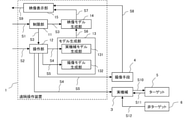
- FIG. 1 is a block diagram showing an example of the configuration of the remote control device 1 according to the first embodiment.
- the remote control device 1 is for the operator to remotely control the actual machine 3 imaged by the image pickup means 4.
- the remote control device 1 includes a restriction unit 11, an operation unit 12, a model generation unit 13, a video model generation unit 14, and a video display unit 15.
- the restriction unit 11 receives restriction information S1 from an operator (not shown).
- the limiting unit 11 generates a movable range S3 based on the limiting information S1 and gives it to the operating unit 12 and the video model generation unit 14.
- the restriction information S1 is information in which the operator sets the movable range of the actual machine 3.
- the movable range S3 is the movable range of the actual machine 3 set by the operator. That is, the limiting unit 11 sets the movable range S3 of the actual machine 3 based on the limiting information S1 from the operator.
- the operation unit 12 receives the operation information S2 from the operator and the movable range S3 from the restriction unit 11.
- the operation unit 12 generates the first command information S4 and the second command information S5 based on the operation information S2 and the movable range S3, and sends the first command information S4 to the actual machine 3 and the actual machine model generation unit 131.
- the second command information S5 is given to the image pickup means 4 and the image pickup model generation unit 132.
- the operation information S2 is an exercise command for remotely controlling the actual machine 3. This movement command is the operation itself of the control stick 121 and the button 122 in the operation unit 12, which will be described later.
- the first command information S4 is input information for operating the actual machine 3.
- the first command information S4 is input information to a driver IC, a microcomputer, or the like that operates the actual machine 3.
- the second command information S5 is input information for operating the image pickup means 4.
- the second command information S5 is a shooting ON / OFF switching command, a magnification adjustment command, and the like to the image pickup means 4.
- the model generation unit 13 receives the first command information S4 and the second command information S5 from the operation unit 12.
- the model generation unit 13 generates model information S6 based on these information and gives it to the video model generation unit 14.
- the model generation unit 13 is an actual machine model generation unit 131 that generates a model of the actual machine 3 using the first command information S4, and an image pickup model generation unit 13 that generates a model of the image pickup means 4 using the second command information S5. It has 132 and.
- the model information S6 is a combination of the model of the actual machine 3 and the model of the image pickup means 4, and is, for example, a three-dimensional model in which the actual machine 3 is virtually projected so as to be seen from a predetermined direction.
- the predetermined direction is the same as the direction in which the image pickup means 4 takes an image of the actual machine 3. That is, the model generation unit 13 outputs model information S6 in which the model of the actual machine 3 and the model of the image pickup means 4 are combined.
- the video model generation unit 14 receives the movable range S3 from the restriction unit 11 and the model information S6 from the model generation unit 13. Based on this information, the video model generation unit 14 generates a movable information video S7 in which the movable range S3 is visualized, and gives it to the video display unit 15.
- the movable information image S7 is an image of the movable range S3 corresponding to the actual machine 3. It was
- the video display unit 15 receives the movable information video S7 from the video model generation unit 14 and the actual machine video S8 from the image pickup means 4.
- the video display unit 15 generates a video S9 based on the movable information video S7 and the actual machine video S8, and presents the video S9 to the operator.
- the image display unit 15 displays the actual machine image S8 and the movable information image S7.
- the actual machine image S8 is an image obtained by photographing the actual machine 3.
- the image display unit 15 adjusts the position of the movable information image S7 so that the position of the three-dimensional model in the movable information image S7 and the position of the actual machine in the actual machine image S8 match.
- the movable information image S7 is superimposed on the actual machine image S8 at an accurate position.
- the position adjustment of the movable information image S7 may be performed by image processing using an image feature point or a marker between the movable information image S7 and the actual machine image S8. Alternatively, it may be performed by correcting the initial positions of the movable information image S7 and the actual machine image S8.
- the method of adjusting the position of the movable information image S7 is not limited to these.
- the video display unit 15 does not need to superimpose and display the actual machine video S8 and the movable information video S7, and for example, each video may be displayed on a separate screen. However, in the following, it will be described as being superimposed and displayed.
- the actual machine 3 receives the first command information S4 from the operation unit 12, the reaction force S11 from the target 5, and the reaction force S12 from the non-target 6.
- the actual machine 3 generates an acting force S10 based on the first command information S4 and gives it to the target 5.
- the target 5 is an object that the actual machine 3 applies an acting force S10 to move.
- the reaction force S11 from the target 5 is generated when the actual machine 3 moves the target 5.
- the reaction force S12 from the non-target 6 is generated when the actual machine 3 moves the target 5 and comes into contact with the non-target 6.
- the image pickup means 4 receives the second command information S5 from the operation unit 12.
- the image pickup means 4 photographs the actual machine 3 based on the second command information S5 to generate the actual machine image S8, and gives it to the image display unit 15.
- Target 5 receives the acting force S10 from the actual machine 3.
- the target 5 applies a reaction force S11 to the actual machine 3 based on the acting force S10.
- the non-target 6 gives a reaction force S12 to the actual machine 3 when the target 5 comes into contact with the non-target 6.
- the reaction force S12 also includes a force from the non-target 6 via the target 5.
- the non-target 6 is an object to which the actual machine 3 intentionally does not apply the acting force S10.
- the image pickup means 4 is always fixed at the same position and the shooting is always ON, the actual machine image S8 can be obtained even if the second command information S5 is not input to the image pickup means 4.
- the second command information S5 does not need to be input to the image pickup means 4, but is input only to the image pickup model generation unit 132. This also applies to the subsequent embodiments.
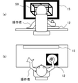
- FIG. 2 (a) and 2 (b) are schematic views showing an example of the configuration including the operation unit 12 in the first embodiment.
- FIG. 2A is a view of the operator from the back
- FIG. 2B is a view of the operator from the top.
- the operator remotely controls the actual machine 3 by using the operation unit 12 while watching the image S9 of the image display unit 15. Since the operation unit 12, the image display unit 15, and the image S9 shown in FIG. 2 are the same as the operation unit 12, the image display unit 15, and the image S9 shown in FIG. 1, the description thereof will be omitted.
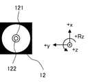
- FIG. 3 is a schematic diagram showing an example of the operation unit 12 in the first embodiment. As shown in FIG. 3, the operation unit 12 has a control stick 121 and a button 122.
- the control stick 121 is a controller that can operate in the x-axis direction, the y-axis direction, and in the xy plane.
- the control stick 121 is used to remotely control the actual machine 3. That is, the actual machine 3 moves according to the operation direction of the control stick 121. For example, when the operator operates the control stick 121 in the + x direction, the actual machine moves in the + x direction.
- the button 122 is a button for moving the actual machine 3 in the z-axis direction. For example, when the operator keeps pressing the button 122, the actual machine 3 moves in the + z direction, and when the button 122 is released, the actual machine 3 moves in the ⁇ z direction. If the button 122 is pressed in this state, the actual machine 3 is stopped.
- the operation unit 12 is not limited to the one having the control stick 121 and the button 122 as shown in FIG.
- the operator may operate with gestures, or the operator may wear and operate an auxiliary device (not shown) simulating the actual machine 3.
- the gesture is an action such as waving a hand toward a camera (not shown) arranged near the operator.
- the actual machine 3 moves according to the gesture or the operation direction of the auxiliary device. For example, when the operator operates in the + x direction using a gesture or an auxiliary device, the actual machine moves in the + x direction.
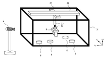
- FIG. 4 is a schematic diagram showing an example of the configuration including the actual machine 3 in the first embodiment. Since the image pickup means 4, the target 5, and the non-target 6 shown in FIG. 4 are the same as the image pickup means 4, the target 5, and the non-target 6 shown in FIG. 1, the description thereof will be omitted.
- the actual machine 3 has an x-axis translation mechanism 31, a y-axis translation mechanism 32, a z-axis translation mechanism 33, and an actual machine end 34.
- the x-axis translation mechanism 31 moves the actual machine end 34 in the x-axis direction. That is, when the operator operates the control stick 121 of the operation unit 12 in the x-axis direction, the x-axis translation mechanism 31 moves the actual machine end 34 in the x-axis direction.
- the y-axis translation mechanism 32 moves the actual machine end 34 in the y-axis direction. That is, when the operator operates the control stick 121 of the operation unit 12 in the y-axis direction, the y-axis translation mechanism 32 moves the actual machine end 34 in the y-axis direction.
- the z-axis translation mechanism 33 moves the actual machine end 34 in the z-axis direction. That is, when the operator presses the button 122 of the operation unit 12, the z-axis translation mechanism 33 moves the actual machine end 34 in the z-axis direction.
- the actual machine end 34 moves based on the operation information S2 from the operator.
- the image pickup means 4 is arranged at a position where the actual machine 3 can be seen in the field of view.
- the image pickup means 4 photographs the actual machine 3 to generate the actual machine image S8.
- the image display unit 15 displays the actual machine image S8. This is similar to a conventional remote control device.
- the image display unit 15 in the first embodiment displays an image S9 in which the actual machine image S8 and the movable information image S7, which is the image of the movable range S3 of the actual machine 3, are superimposed.
- a method of setting the movable range S3 in the limiting unit 11 will be described.
- the limiting unit 11 has five modes (hereinafter referred to as "first mode”, “second mode”, “third mode”, “fourth mode”, and “fifth mode”).
- the movable range S3 of the actual machine 3 is set by any one of the modes.
- the first mode is a mode in which the movable range S3 is set by means for forcibly limiting the operation of the operation unit 12.
- the second mode is a mode in which the movable range S3 is set by pressing the button corresponding to the direction in which the movement is possible.
- the third mode is a mode in which the movable range S3 is set by the movable pattern prepared in advance.
- the fourth mode is a mode in which the movable range S3 is set by a straight line or a curve connecting a plurality of restraint points.
- the fifth mode is a mode in which the movable range S3 is set by the light source model generation unit 133 that generates a model of the light source that emits light.
- the operation unit 12 has means for forcibly limiting the operation from the operator.
- the limiting unit 11 sets the movable range S3 by this means.
- the means for forcibly limiting is to physically limit the operable range of the operation unit 12.
- the x-axis translation plate 11a and the y-axis translation plate 11b which will be described later.
- 5 (a) and 5 (b) are schematic views showing an example of the limiting unit 11 when the movable range S3 is set in the first mode in the first embodiment.
- FIG. 5A is a schematic diagram when the limiting portion 11 is the x-axis translation plate 11a.
- FIG. 5B is a schematic diagram when the limiting portion 11 is a y-axis translation plate 11b.
- the x-axis translation plate 11a shown in FIG. 5A is attached to the operation unit 12. Thereby, the operation of the control stick 121 can be restricted in the x-axis direction.
- the y-axis translation plate 11b shown in FIG. 5B is attached to the operation unit 12. As a result, the operation of the control stick 121 can be restricted in the y-axis direction.
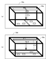
- FIG. 6A and 6 (b) are schematic views showing an example of the image S9 on the image display unit 15 when the movable range S3 is set in the first mode in the first embodiment.
- FIG. 6A is a schematic view of the image S9a when the x-axis translation plate 11a is attached to the operation unit 12.
- FIG. 6B is a schematic view of the image S9b when the y-axis translation plate 11b is attached to the operation unit 12.
- the image S9a is an image in which the actual machine image S8a and the movable information image S7a are superimposed.
- the actual machine image S8a is an image of the actual machine 3 taken by the image pickup means 4.
- the movable information video S7a is a video of the movable range S3 generated by the video model generation unit 14.
- the movable information image S7a is an image of the movable range S3 in the same direction as the x-axis direction, and is displayed on the upper side and the lower side of the actual machine image S8a.
- the image S9b is an image in which the actual machine image S8a and the movable information image S7b are superimposed.
- the movable information video S7b is a video of the movable range S3 generated by the video model generation unit 14.
- the movable information image S7b is an image of the movable range S3 in the same direction as the y-axis direction, and is displayed on the upper side and the lower side of the actual machine image S8a.
- the video model generation unit 14 identifies that the movable range S3 is in the x-axis direction. Similarly, when the y-axis translation plate 11b is attached to the operation unit 12, the video model generation unit 14 identifies that the movable range S3 is in the y-axis direction. Further, the video model generation unit 14 matches the identified information with the model information S6 from the model generation unit 13 to generate the movable information video S7a. Instead of the model information S6, it may be spatial information acquired by image processing the actual machine image S8a, that is, vector information corresponding to the x-axis direction in the actual machine image S8a. In this case, the video model generation unit 14 matches the identified information with the spatial information to generate the movable information video S7a. This is the same even when the y-axis translation plate 11b is attached to the operation unit 12.
- the movable information images S7a and S7b are displayed on the upper side and the lower side in the actual machine image S8a, respectively, but they are in the same direction as the movable range S3.
- the place where it is displayed is not limited. For example, it may be in the center of the actual machine image S8a. This also applies to the subsequent embodiments.
- the image display unit 15 may superimpose the image of the position of the actual machine end 34 on the xy plane on the images S9a and S9b.
- a projection point (not shown) of the end 34 of the actual machine on the xy plane is superimposed on the movable information images S7a and S7b.
- the x-coordinate and y-coordinate of this projection point are the x-coordinate and y-coordinate of the actual machine end 34, and correspond to the operation amount in the x-axis direction and the operation amount in the y-axis direction of the control stick 121, respectively.
- the information regarding the manipulated variable is included in the model information S6.
- the video model generation unit 14 generates an image of the projection point based on the model information S6, and the image display unit 15 superimposes the image of the projection point on the images S9a and S9b. This also applies to the subsequent embodiments. By superimposing the projection points on the images S9a and S9b, the operability of the actual machine 3 is improved.
- the limiting portion 11 in the first mode is not limited to the x-axis translation plate 11a and the y-axis translation plate 11b, and may be, for example, an oblique translation plate (not shown), or the x-axis direction and y (not shown). It may be a translation plate that can move in both axial directions.
- the gesture may be a gesture of the operator waving his hand, or the operator may wear an auxiliary device (not shown) simulating an actual machine. In the case of a gesture, after setting the movable range S3 of the actual machine 3 by the gesture, the actual machine 3 is remotely controlled by the same gesture.
- the auxiliary device itself has a structure in which the movable range S3 is limited. That is, when the operator wears the auxiliary device, the actual machine 3 is remotely controlled while the movable range S3 is limited.
- One example is a mobile suit.
- the operator When the movable range S3 is set in the first mode, the operator operates the operation unit 12 while checking the movable information video S7a or S7b in a state where the movable range S3 is limited. This makes it possible to improve work efficiency in remotely controlling the actual machine 3.
- the operation unit 12 has a button corresponding to the direction in which the movement is possible.
- the limiting unit 11 sets the movable range S3 by pressing this button.
- FIG. 7 is a schematic diagram showing an example of the limiting unit 11 when the movable range S3 is set in the second mode in the first embodiment.
- FIG. 7 is a schematic diagram when the limiting unit 11 is the x-axis limiting button 11c and the y-axis limiting button 11d.
- the x-axis limit button 11c and the y-axis limit button 11d shown in FIG. 7 are provided on the operation unit 12.
- the operation of the control stick 121 can be restricted in the x-axis direction.
- the operation of the control stick 121 can be restricted in the y-axis direction.
- the x-axis restriction button 11c and the y-axis restriction button 11d do not necessarily have to be provided in the operation unit 12, and may be provided anywhere near the operator.
- FIG. 8A and 8 (b) are schematic views showing an example of the image S9 on the image display unit 15 when the movable range S3 is set in the second mode in the first embodiment.
- FIG. 8A is a schematic diagram of the image S9a when the x-axis restriction button 11c is pressed.
- FIG. 8B is a schematic diagram of the image S9b when the y-axis restriction button 11d is pressed. Since the video S9a of FIG. 8A is the same as the video S9a of FIG. 6A and the video S9b of FIG. 8B is the same as the video S9b of FIG. 6B, the description thereof is omitted. do.
- the video model generation unit 14 identifies that the movable range S3 is in the x-axis direction. As a result, the movable information video S7a is generated. Similarly, when the y-axis restriction button 11d is pressed, the video model generation unit 14 identifies that the movable range S3 is in the y-axis direction. As a result, the movable information video S7b is generated.
- the movable range S3 becomes both the x-axis direction and the y-axis direction.
- the structure may be such that when the x-axis restriction button 11c is pressed, the x-axis direction is constrained, and when the y-axis restriction button 11d is pressed, the y-axis direction is constrained.
- FIG. 9 is a schematic diagram showing an example of the limiting unit 11 when the movable range S3 is set in the third mode in the first embodiment.
- the restriction patterns 11e to 11j are displayed on the video S9c from the video display unit 15.
- the restriction patterns 11e to 11j are exercise patterns prepared in advance. The operator selects any one of the restriction patterns 11e to 11j by using the operation unit 12 before remotely controlling the actual machine 3. For example, when the operator selects the restriction pattern 11e, the control stick 121 is used to move the cursor 11k to the restriction pattern 11e, and the button 122 is pressed. As a result, the limiting unit 11 sets the movable range S3 in the x-axis direction.
- the exerciseable pattern is not limited to the restriction patterns 11e to 11j.
- the image display unit 15 has a touch display function, and the operator may manually operate the screen to select from the restriction patterns 11e to 11j. This eliminates the need for the cursor 11k and enables simple operation.
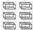
- FIG. 10A to 10 (f) are schematic views showing an example of the image S9 on the image display unit 15 when the movable range S3 is set in the third mode in the first embodiment.
- FIG. 10A is a schematic diagram of the image S9a when the restriction pattern 11e is selected.
- FIG. 10B is a schematic diagram of the image S9b when the restriction pattern 11f is selected.
- FIG. 10C is a schematic diagram of the image S9d when the restriction pattern 11g is selected.
- FIG. 10D is a schematic diagram of the image S9e when the restriction pattern 11h is selected.
- FIG. 10E is a schematic diagram of the image S9f when the restriction pattern 11i is selected.
- FIG. 10 (f) is a schematic diagram of the image S9g when the restriction pattern 11j is selected.
- the image S9d is an image in which the actual machine image S8a and the movable information image S7c are superimposed.
- the actual machine image S8a is an image of the actual machine 3 taken by the image pickup means 4.
- the movable information video S7c is a video of the movable range S3 generated by the video model generation unit 14.
- the movable information image S7c is an image of the movable range S3 in the diagonal direction.
- the image S9e is an image in which the actual machine image S8a and the movable information image S7d are superimposed.
- the actual machine image S8a is an image of the actual machine 3 taken by the image pickup means 4.
- the movable information video S7d is a video of the movable range S3 generated by the video model generation unit 14.
- the movable information image S7d is an image of the movable range S3 in the diagonal direction.
- the image S9f is an image in which the actual machine image S8a and the movable information image S7e are superimposed.
- the actual machine image S8a is an image of the actual machine 3 taken by the image pickup means 4.
- the movable information video S7e is a video of the movable range S3 generated by the video model generation unit 14.
- the movable information image S7e is an image of the movable range S3 in the same direction as the x-axis direction and the same direction as the y-axis direction.
- the image S9g is an image in which the actual machine image S8a and the movable information image S7f are superimposed.
- the actual machine image S8a is an image of the actual machine 3 taken by the image pickup means 4.
- the movable information video S7f is a video of the movable range S3 generated by the video model generation unit 14.
- the movable information image S7f is an image of two diagonally movable ranges S3.
- the video model generation unit 14 identifies that the movable range S3 is in the x-axis direction. As a result, the movable information video S7a is generated. The same applies even when the limiting portions 11f to 11j are selected.
- the limiting unit 11 sets the movable range S3 by a straight line or a curve connecting a plurality of restraint points.
- 11 (a) to 11 (d) are schematic views showing an example of the limiting unit 11 when the movable range S3 is set in the fourth mode in the first embodiment.
- the operator sets the movable range S3 using the operation unit 12 while watching the video S9h.
- the control stick 121 is used to move the cursor 11ma to an arbitrary position in the limiting portion 11m, and the button 122 is pressed to set a plurality of restraint points.
- four restraint points 11md, 11me, 11mf, and 11mg are set in order.
- press the OK button 11mb to complete the setting of the movable range S3. If the CANCEL button 11mc is pressed during the setting, the setting returns to the previous constraint point setting.
- the state returns to the state in which the constraint point 11me is set. This makes it possible to reset the constraint point.
- the straight line connecting the four restraint points 11md, 11me, 11mf, and 11mg is the movable range S3.
- the operator sets the movable range S3 using the operation unit 12 while watching the video S9i.
- the control stick 121 is used to move the cursor 11na to an arbitrary position in the limiting portion 11n, and the button 122 is pressed to set a plurality of restraint points.
- four constraint points 11nd, 11ne, 11nf, and 11ng are set in order.
- press the OK button 11nb to complete the setting of the movable range S3.
- the cursor 11na is moved while pressing the button 122.
- the movable range S3 according to the movement path is set, and it can be a straight line or an arbitrary curve.
- the operation unit 12 has a function of automatically correcting this, and the distortion can be eliminated by the correction.
- the CANCEL button 11nc is pressed during the setting, the setting returns to the previous constraint point setting. For example, if the CANCEL button 11nc is pressed after setting the constraint point 11nf, the state where the constraint point 11ne is set returns to the set state. This makes it possible to reset the constraint point.
- the curve connecting the four restraint points 11nd, 11ne, 11nf, and 11ng is the movable range S3.
- the operator sets the movable range S3 using the operation unit 12 while watching the video S9j.
- the control stick 121 is used to move the cursor 11 Wheela to an arbitrary position in the restriction portion 11 Europe, and the button 122 is pressed to set a plurality of restraint points.
- the four constraint points 11 Mrd, 11 Righte, 11 Rightf, and 11 Rightg are set in order, and the constraint points 11 Mrd are set again.
- press the OK button 11 Mrb to complete the setting of the movable range S3. If the CANCEL button 11 Cosmeticc is pressed during the setting, the setting returns to the previous constraint point setting.
- the operator sets the movable range S3 using the operation unit 12 while watching the video S9k.
- the control stick 121 is used to move the cursor 11pa to an arbitrary position in the limiting portion 11p, and the button 122 is pressed to set a plurality of restraint points.
- the four constraint points 11pd, 11pe, 11 pf, and 11 pg are set in order, and the constraint points 11 pd are set again.
- press the OK button 11pb After setting, press the OK button 11pb to complete the setting of the movable range S3.
- the cursor is moved while pressing the button 122.
- the movable range S3 according to the movement path is set, and it can be a straight line or an arbitrary curve.
- the operation unit 12 has a function of automatically correcting this, and the distortion can be eliminated by the correction.
- the CANCEL button 11pc is pressed during the setting, the setting returns to the previous constraint point setting. For example, if the CANCEL button 11pc is pressed after setting the constraint point 11 pf, the state returns to the state in which the constraint point 11 pe is set. This makes it possible to reset the constraint point.
- the curve connecting the four restraint points 11pd, 11pe, 11pf, and 11pg, or the region surrounded by the curve is the movable range S3. Whether it is a straight line or an area can be selected in advance.
- the image display unit 15 has a touch display function, and the operator may manually operate the screen to set the movable range S3. This eliminates the need for cursors 11ma, 11na, 11 Cincinnatia, and 11pa, and enables simple operation.
- FIG. 12A is a schematic diagram of an image S9m in which the movable range S3 is set by the limiting unit 11m and the movable information image S7g generated by the image model generation unit 14 is superimposed on the actual machine image S8a.
- FIG. 12B is a schematic diagram of an image S9n in which the movable range S3 is set by the limiting unit 11n and the movable information image S7h generated by the image model generation unit 14 is superimposed on the actual machine image S8a.
- FIG. 12A is a schematic diagram of an image S9m in which the movable range S3 is set by the limiting unit 11m and the movable information image S7g generated by the image model generation unit 14 is superimposed on the actual machine image S8a.
- FIG. 12B is a schematic diagram of an image S9n in which the movable range S3 is set by the limiting unit 11n and the movable information image S7h generated by the image model generation unit 14 is superimposed on the actual machine image
- FIG. 12C is a schematic diagram of an image S9 Economics in which the movable range S3 is set by the limiting unit 11 1958 and the movable information image S7i generated by the image model generation unit 14 is superimposed on the actual machine image S8a.
- FIG. 12D is a schematic diagram of an image S9p in which the movable range S3 is set by the limiting unit 11p and the movable information image S7j generated by the image model generation unit 14 is superimposed on the actual machine image S8a.
- FIG. 12 (e) is a schematic diagram of another image S9q in which the movable range S3 is set by the limiting unit 11 1958 and the movable information image S7k generated by the image model generation unit 14 is superimposed on the actual machine image S8a.
- FIG. 12 (f) is a schematic diagram of another image S9r in which the movable range S3 is set by the limiting unit 11p and the movable information image S7m generated by the image model generation unit 14 is superimposed on
- the image S9m is an image in which the actual machine image S8a and the movable information image S7g are superimposed.
- the actual machine image S8a is an image of the actual machine 3 taken by the image pickup means 4.
- the movable information image S7g is an image of the movable range S3 generated by the image model generation unit 14.
- the movable information image S7g is an image of the movable range S3 which is a straight line connecting the four restraint points.
- the video S9n is a video in which the actual machine video S8a and the movable information video S7h are superimposed.
- the actual machine image S8a is an image of the actual machine 3 taken by the image pickup means 4.
- the movable information video S7h is a video of the movable range S3 generated by the video model generation unit 14.
- the movable information image S7h is an image of the movable range S3 which is a curve connecting the four restraint points.
- the image S9ello is an image in which the actual machine image S8a and the movable information image S7i are superimposed.
- the actual machine image S8a is an image of the actual machine 3 taken by the image pickup means 4.
- the movable information video S7i is a video of the movable range S3 generated by the video model generation unit 14.
- the movable information image S7i is an image of the movable range S3 which is a straight line connecting the four restraint points.
- the video S9p is a video in which the actual machine video S8a and the movable information video S7j are superimposed.
- the actual machine image S8a is an image of the actual machine 3 taken by the image pickup means 4.
- the movable information video S7j is a video of the movable range S3 generated by the video model generation unit 14.
- the movable information image S7j is an image of the movable range S3 which is a curve connecting the four restraint points.
- the image S9q is an image in which the actual machine image S8a and the movable information image S7k are superimposed.
- the actual machine image S8a is an image of the actual machine 3 taken by the image pickup means 4.
- the movable information video S7k is a video of the movable range S3 generated by the video model generation unit 14.
- the movable information image S7k is an image of the movable range S3 which is a region surrounded by a straight line connecting four restraint points.
- the image S9r is an image in which the actual machine image S8a and the movable information image S7m are superimposed.
- the actual machine image S8a is an image of the actual machine 3 taken by the image pickup means 4.
- the movable information image S7m is an image of the movable range S3 generated by the image model generation unit 14.
- the movable information image S7m is an image of the movable range S3 which is a region surrounded by a curve connecting four restraint points.
- the video model generation unit 14 identifies that the movable range S3 is a straight line connecting the four constraint points. As a result, the movable information image S7g is generated. The same applies even when the movable range S3 is set by the limiting portions 11n to 11p.
- FIG. 13 is a block diagram showing an example of the configuration of the model generation unit 13 when the movable range S3 is set in the fifth mode in the first embodiment.
- the operation unit 12 further generates third command information S13, which is input information for operating the light source that emits light, based on the movable range S3 from the restriction unit 11.
- the model generation unit 13 further includes a light source model generation unit 133 that generates a light source model using the third command information S13, and is a model in which a model of the actual machine 3, a model of the image pickup means 4, and a light source model are combined.
- Information S6 is output.
- the model generation unit 13 has a first command information S4 from the operation unit 12 to the actual machine model generation unit 131, a second command information S5 from the operation unit 12 to the imaging model generation unit 132, and a light source model generation unit from the operation unit 12.
- Model information S6 is generated based on the third command information S13 to 133, and is given to the video model generation unit 14.
- the third command information S13 is input information for operating a light source that emits light.
- the third command information S13 is a power ON / OFF switching command to the light source and input information for rotating the light source in the xy plane.
- FIG. 14 is a schematic diagram showing an example of the operation unit 12 when the movable range S3 is set in the fifth mode in the first embodiment.
- FIG. 14 is a schematic view of the case where the control stick 121 shown in FIG. 3 can rotate in the Rz direction and has the function of the limiting unit 11. Counterclockwise is the + Rz direction, and clockwise is the -Rz direction.
- the direction vector of the control stick 121 when the button 122 is pressed is set as the movable range S3.
- the operator may set a plurality of direction vectors.
- the control stick 121 is rotated on the xy plane, and the operation of pressing the button 122 is repeated.
- a plurality of direction vectors are set as the movable range S3.
- a region surrounded by a plurality of direction vectors is set as the movable range S3. Whether to use a plurality of direction vectors or a region can be selected in advance.
- FIG. 15 is a schematic diagram showing an example of the image S9 on the image display unit 15 when the movable range S3 is set in the fifth mode in the first embodiment.
- FIG. 15 is a schematic diagram of the image S9s when the movable range S3 is set by the control stick 121.
- the video S9s is a video in which the actual machine video S8a and the movable information video S7n are superimposed.
- the actual machine image S8a is an image of the actual machine 3 taken by the image pickup means 4.
- the movable information video S7n is a video of the movable range S3 generated by the video model generation unit 14.
- the movable information image S7n includes an image of the movable range S3 represented by a direction vector and an image of model information from the light source model generation unit 133 of the model information S6.
- FIG. 16 is a schematic diagram showing an example of another video S9 on the video display unit 15 when the movable range S3 is set in the fifth mode in the first embodiment.
- FIG. 16 is a schematic diagram of the image S9t when two direction vectors are set by the control stick 121 and the area surrounded by the two direction vectors is selected as the movable range S3.
- the video S9t is a video in which the actual machine video S8a and the movable information video S7 Europe are superimposed.
- the actual machine image S8a is an image of the actual machine 3 taken by the image pickup means 4.
- the movable information video S7 Europe is a video of the movable range S3 generated by the video model generation unit 14.
- the image of the movable range S3 represented by the region surrounded by the two direction vectors and the image of the model information from the light source model generation unit 133 of the model information S6 are displayed. included.
- the movable range S3 of the actual machine 3 is set by the limiting unit 11. As a result, complicated remote control of the actual machine 3 can be avoided. Further, the movable information image S7 generated based on the movable range S3 from the limiting unit 11 and the model information S6 from the model generation unit 13 and the actual machine image S8 generated by the imaging means 4 are superimposed. The video S9 is generated by the video display unit 15. As a result, the actual machine 3 can be remotely controlled while checking the movable range S3, and the work efficiency can be improved as compared with the conventional case.
- FIG. 17 is a block diagram showing an example of the configuration of the remote control device 1 according to the second embodiment.
- the remote control device 1 includes a restriction unit 11, an operation unit 12, and a video display unit 15. Since the limiting unit 11, the actual machine 3, the target 5, and the non-target 6 shown in FIG. 17 are the same as the limiting unit 11, the actual machine 3, the target 5, and the non-target 6 shown in FIG. 1, the description thereof will be omitted. ..
- the operation unit 12 receives the operation information S2 from the operator and the movable range S3 from the restriction unit 11.
- the operation unit 12 generates the first command information S4, the second command information S5, and the fourth command information S14 based on these information, gives the first command information S4 to the actual machine 3, and gives the second command information S5. Is given to the image pickup means 4, and the fourth command information S14 is given to the movable range forming means 7.
- the fourth command information S14 will be described later.
- the image display unit 15 receives the actual machine image S8 and the movable information image S15 from the image pickup means 4.
- the video display unit 15 generates a video S9 in which these videos are superimposed and presents the video S9 to the operator.
- the movable information image S15 is an image of the movable range S3 directly captured by the image pickup means 4.
- the image pickup means 4 receives the second command information S5 from the operation unit 12.
- the image pickup means 4 gives the actual machine image S8 and the movable information image S15 to the image display unit 15 based on the second command information S5.
- the movable range forming means 7 forms the movable range S3 of the actual machine 3.
- the movable range forming means 7 receives the fourth command information S14 from the operation unit 12.
- the movable range forming means 7 is connected to the actual machine 3, but if the movable range S3 can be shown in the actual machine 3, it may not be connected to the actual machine 3.
- the movable range forming means 7 is, for example, a light source that emits light, such as a laser light source or an LED light source. In this case, the pattern of light emitted from the light source and imaged in and around the actual machine 3 becomes the movable range S3. The light pattern is captured by the image pickup means 4 and becomes an image, which is displayed on the image display unit 15.
- the light source emits light having a wavelength that can be photographed by the image pickup means 4.
- the light source is a laser having a wavelength in the infrared region.
- the fourth command information S14 is input information for operating the movable range forming means 7 that forms the movable range S3 of the actual machine 3.
- the fourth command information S14 is a power ON / OFF switching command to the movable range forming means 7 and input information for rotating the movable range forming means 7 in the xy plane.
- the operation unit 12 in the second embodiment is the same as the operation unit 12 shown in FIG. That is, the control stick 121 can also rotate in the Rz direction and has the function of the limiting unit 11.
- the method of setting the movable range S3 is the same as the setting method described with reference to FIG.
- FIG. 18 is a schematic diagram showing an example of the configuration including the actual machine 3 in the second embodiment. Since the actual machine 3, the image pickup means 4, the target 5, and the non-target 6 shown in FIG. 18 are the same as the actual machine 3, the image pickup means 4, the target 5, and the non-target 6 shown in FIG. 4, the description thereof will be omitted. ..
- the movable range forming means 7 is connected near the center of the z-axis translation mechanism 33.
- the movable range forming means 7 is a laser light source 71, and the laser beam 72 is output from the laser light source 71.
- the output direction of the laser beam 72 is set by using the control stick 121.
- the movable range forming means 7 is arranged near the center of the z-axis translation mechanism 33, but the present invention is not limited to this. For example, it may be arranged above or below the z-axis translation mechanism 33. Further, it may be arranged outside the actual machine 3.
- FIG. 19 is a schematic diagram showing an example of another configuration including the actual machine 3 in the second embodiment. Since the actual machine 3, the image pickup means 4, the target 5, and the non-target 6 shown in FIG. 19 are the same as the actual machine 3, the image pickup means 4, the target 5, and the non-target 6 shown in FIG. 4, the description thereof will be omitted. ..
- the movable range forming means 7 is connected near the center of the z-axis translation mechanism 33.
- the movable range forming means 7 is the multi-laser light source 73, and the multi-laser ray 74 is output.
- the output direction of the multi-laser ray 74 is set by using the control stick 121.
- the movable range forming means 7 is arranged near the center of the z-axis translation mechanism 33, but the present invention is not limited to this. For example, it may be arranged above or below the z-axis translation mechanism 33. Further, it may be arranged outside the actual machine 3.
- the movable range forming means 7 is the laser light source shown in FIG. 18, when the operator rotates the control stick 121 in the xy plane and presses the button 122, the direction of the control stick 121 when the button 122 is pressed.
- the vector is set as the movable range S3.
- the movable range forming means 7 is the multi-laser light source shown in FIG. 19, when the operator rotates the control stick 121 in the xy plane and presses the button 122 twice, the two direction vectors can move. It is set as the range S3. Alternatively, the area surrounded by the two direction vectors is set as the movable range S3. Whether it is a two-direction vector or a region can be selected in advance.
- FIG. 20 is a schematic diagram showing an example of the image S9 on the image display unit 15 in the second embodiment.
- FIG. 20 is a schematic diagram of the image S9u when the movable range S3 is set by the control stick 121.
- the video S9u is a video in which the actual machine video S8b and the movable information video S15a are superimposed.
- the actual machine image S8b is an image of the actual machine 3 and the movable range forming means 7 taken by the image pickup means 4.
- the movable information image S15a is an image of the movable range S3 taken by the image pickup means 4.
- the movable information image S15a is an image of the movable range S3 represented by the direction vector.
- FIG. 21 is a schematic diagram showing an example of another video S9 in the video display unit 15 in the second embodiment.
- FIG. 21 is a schematic diagram of the image S9v when two direction vectors are set by the control stick 121 and the area surrounded by the two direction vectors is selected as the movable range S3.
- the video S9v is a video in which the actual machine video S8c and the movable information video S15b are superimposed.
- the actual machine image S8c is an image of the actual machine 3 and the movable range forming means 7 taken by the image pickup means 4.
- the movable information image S15b is an image of the movable range S3 taken by the image pickup means 4.
- the movable information image S15b is an image of the movable range S3 represented by the region surrounded by the two direction vectors.
- both the actual machine image S8 and the movable information image S15 are generated by the image pickup means 4.
- the model generation unit 13 and the video model generation unit 14 of the first embodiment can be eliminated.
- FIG. 22 is a block diagram showing an example of the configuration of the remote control device 1 according to the third embodiment.
- the remote control device 1 includes a restriction unit 11, an operation unit 12, a model generation unit 13, a video model generation unit 14, and a video display unit 15.
- FIG. 22 is a block diagram showing a configuration in which a drive model generation unit 134 and a drive device 8 are added to the configuration of the first embodiment shown in FIG.
- the restriction unit 11, the image model generation unit 14, the image display unit 15, the actual machine 3, the image pickup means 4, the target 5, and the non-target 6 shown in FIG. 22 are the restriction unit 11 and the image model generation unit 14 shown in FIG. Since it is the same as the image display unit 15, the actual machine 3, the image pickup means 4, the target 5, and the non-target 6, the description thereof will be omitted.
- the operation unit 12 receives the operation information S2 from the operator and the movable range S3 from the restriction unit 11.
- the operation unit 12 generates the first command information S4, the second command information S5, and the fifth command information S16 based on these information, and the first command information S4 is sent to the actual machine 3 and the actual machine model generation unit 131.
- the second command information S5 is given to the image pickup means 4 and the image pickup model generation unit 132
- the fifth command information S16 is given to the drive device 8 and the drive model generation unit 134.
- the fifth command information S16 will be described later.
- the model generation unit 13 further has a drive model generation unit 134 that generates a model of the drive device 8 that drives the image pickup means 4 by using the fifth command information S16 generated by the operation unit 12.
- the model generation unit 13 has a first command information S4 from the operation unit 12 to the actual machine model generation unit 131, a second command information S5 from the operation unit 12 to the imaging model generation unit 132, and a drive model generation unit from the operation unit 12.
- Model information S6 is generated based on the fifth command information S16 to 134, and is given to the video model generation unit 14.
- the fifth command information S16 is input information for operating the drive device 8 that drives the image pickup means 4.
- the fifth command information S16 is control information for controlling the drive device 8.
- the drive device 8 is connected to the image pickup means 4 and receives the fifth command information S16 from the operation unit 12.
- the drive device 8 rotates based on the fifth command information S16.
- the direction of the image pickup means 4 changes, and the direction in which the actual machine 3 is photographed can be changed.
- the light source model generation unit 133 shown in FIG. 13 may be added to the model generation unit 13 of FIG. 22. ..
- the model generation unit 13 outputs model information S6 that combines the model of the actual machine 3, the model of the image pickup means 4, the model of the light source, and the model of the drive device 8.
- the model generation unit 13 in the present embodiment may have the actual machine model generation unit 131, the image pickup model generation unit 132, and the drive model generation unit 134, and does not necessarily have the light source model generation unit 133. May be good.
- the model information S6 may be a combination of the model of the actual machine 3, the model of the image pickup means 4, and the model of the drive device 8, and it is not always necessary to combine the model of the light source.
- FIG. 23 is a block diagram showing an example of another configuration of the remote control device 1 according to the third embodiment.
- the remote control device 1 includes a restriction unit 11, an operation unit 12, and a video display unit 15.
- FIG. 23 is a block diagram showing a configuration in which a drive device 8 is added to the configuration of the second embodiment shown in FIG.
- the limiting unit 11, the image display unit 15, the actual machine 3, the imaging means 4, the target 5, the non-target 6, and the movable range forming means 7 shown in FIG. 23 are the limiting unit 11 and the image display unit 15 shown in FIG. Since it is the same as the actual machine 3, the image pickup means 4, the target 5, the non-target 6, and the movable range forming means 7, the description thereof will be omitted. Further, since the drive device 8 shown in FIG. 23 is the same as the drive device 8 shown in FIG. 22, the description thereof will be omitted.
- the operation unit 12 receives the operation information S2 from the operator and the movable range S3 from the restriction unit 11.
- the operation unit 12 generates the first command information S4, the second command information S5, the fourth command information S14, and the fifth command information S16 based on these information, and gives the first command information S4 to the actual machine 3.
- the second command information S5 is given to the image pickup means 4
- the fourth command information S14 is given to the movable range forming means 7
- the fifth command information S16 is given to the drive device 8.
- the operation unit 12 in the third embodiment is the same as the operation unit 12 shown in FIG.
- the operator can remotely control the actual machine 3 while adjusting the orientation of the image pickup means 4 by switching between a mode for changing the orientation of the image pickup means 4 and a mode for remotely controlling the actual machine 3. Switching between the two is performed by means (not shown).
- the control stick 121 is operated in the x-axis direction or the y-axis direction. As a result, the direction of the image pickup means 4 is changed in the x-axis direction or the y-axis direction.
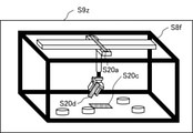
- FIG. 24 is a schematic diagram showing an example of the configuration including the actual machine 3 in the third embodiment.
- FIG. 24 is a schematic diagram when operating the actual machine 3 using the remote control device 1 shown in FIG. 22. Since the actual machine 3, the image pickup means 4, the target 5, and the non-target 6 shown in FIG. 24 are the same as the actual machine 3, the image pickup means 4, the target 5, and the non-target 6 shown in FIG. 4, the description thereof will be omitted. ..
- the drive device 8 is connected to the image pickup means 4, and changes the direction of the image pickup means 4 based on the fifth command information S16 from the operation unit 12.
- the orientation of the actual machine image S8 on the image display unit 15 is switched according to the orientation of the image pickup means 4.
- the orientation of the image pickup means 4 is changed by the drive device 8.
- the operator can operate the actual machine 3 while sequentially changing the orientation of the actual machine image S8, and can efficiently perform remote control.
- FIG. 25 is a block diagram showing an example of the configuration of the remote control device 1 according to the fourth embodiment.
- the remote control device 1 includes a restriction unit 11, an operation unit 12, a model generation unit 13, a video model generation unit 14, and a video display unit 15.
- FIG. 25 is a block diagram showing a configuration in which a manipulator model generation unit 135 and a manipulator 9 are added to the configuration of the first embodiment shown in FIG. Since the actual machine 3, the image pickup means 4, the target 5, and the non-target 6 shown in FIG. 25 are the same as the actual machine 3, the image pickup means 4, the target 5, and the non-target 6 shown in FIG. 1, the description thereof will be omitted. ..
- the restriction unit 11 receives the restriction information S1 from the operator.
- the limiting unit 11 generates a movable range S3, an openable / closable range S17, and a posture limiting range S18 based on the limited information S1, and gives them to the operation unit 12 and the video model generation unit 14.
- the openable / closable range S17 is a range in which the manipulator 9 can be opened / closed.
- the posture restriction range S18 is a posture when the manipulator 9 is restricted to a predetermined posture, in other words, an inclination when the manipulator 9 is restricted to a predetermined inclination.
- the operation unit 12 receives the operation information S2 from the operator, the movable range S3 from the limiting unit 11, the openable / closable range S17 from the limiting unit 11, and the posture limiting range S18 from the limiting unit 11.
- the operation unit 12 generates the first command information S4, the second command information S5, and the sixth command information S19 based on these information, and the first command information S4 is sent to the actual machine 3 and the actual machine model generation unit 131.
- the second command information S5 is given to the image pickup means 4 and the image pickup model generation unit 132, and the sixth command information S19 is given to the manipulator 9 and the manipulator model generation unit 135.
- the sixth command information S19 is input information for operating the manipulator 9 connected to the actual machine 3.
- the sixth command information S19 is input information to a driver IC, a microcomputer, or the like that operates the manipulator 9.
- the model generation unit 13 further has a manipulator model generation unit 135 that generates a model of the manipulator 9 using the sixth command information S19 generated by the operation unit 12.
- the model generation unit 13 has a first command information S4 from the operation unit 12 to the actual machine model generation unit 131, a second command information S5 from the operation unit 12 to the imaging model generation unit 132, and a manipulator model generation unit from the operation unit 12.
- Model information S6 is generated based on the sixth command information S19 to 135, and is given to the video model generation unit 14.
- the video model generation unit 14 receives the movable range S3 from the restriction unit, the open / closeable range S17, the posture restriction range S18, and the model information S6 from the model generation unit 13. Based on this information, the image model generation unit 14 generates a movable information image S20 which is an image of the movable range S3, the open / closeable range S17, and the posture limiting range S18, and gives the movable information image S20 to the image display unit 15.
- the video display unit 15 receives the movable information video S20 from the video model generation unit 14 and the actual machine video S8 from the image pickup means 4.
- the video display unit 15 generates a video S9 in which these videos are superimposed and presents the video S9 to the operator.
- the manipulator 9 is connected to the actual machine 3 and receives the sixth command information S19 from the operation unit 12.
- the light source model generation unit 133 shown in FIG. 13 may be added to the model generation unit 13 of FIG. 25. ..
- the drive model generation unit 134 in the third embodiment may be added to the model generation unit 13, or the image pickup means 4 may be connected to the drive device 8 and the orientation may be changed.
- the model generation unit 13 outputs model information S6 that combines the model of the actual machine 3, the model of the image pickup means 4, the model of the light source, the model of the drive device 8, and the model of the manipulator 9.
- the model generation unit 13 in the present embodiment may have an actual machine model generation unit 131, an image pickup model generation unit 132, and a manipulator model generation unit 135, and does not necessarily have a light source model generation unit 133 and a drive model generation unit 134. It is not necessary to have and. Further, the model information S6 may be a combination of the model of the actual machine 3, the model of the image pickup means 4, and the model of the manipulator 9, and it is not always necessary to combine the model of the light source and the model of the drive device 8. ..
- FIG. 26 is a block diagram showing an example of another configuration of the remote control device 1 according to the fourth embodiment.
- the remote control device 1 includes a restriction unit 11, an operation unit 12, and a video display unit 15.
- FIG. 26 is a block diagram showing a configuration in which a manipulator 9 is added to the configuration of the second embodiment shown in FIG.
- the limiting unit 11, the image display unit 15, the actual machine 3, the imaging means 4, the target 5, the non-target 6, and the movable range forming means 7 shown in FIG. 26 are the limiting unit 11 and the image display unit 15 shown in FIG. Since it is the same as the actual machine 3, the image pickup means 4, the target 5, the non-target 6, and the movable range forming means 7, the description thereof will be omitted. Further, since the manipulator 9 shown in FIG. 26 is the same as the manipulator 9 shown in FIG. 25, the description thereof will be omitted.
- the operation unit 12 receives the operation information S2 from the operator and the movable range S3 from the restriction unit 11.
- the operation unit 12 generates the first command information S4, the second command information S5, the fourth command information S14, and the sixth command information S19 based on these information, and gives the first command information S4 to the actual machine 3.
- the second command information S5 is given to the image pickup means 4
- the fourth command information S14 is given to the movable range forming means 7
- the sixth command information S19 is given to the manipulator 9.
- the limiting unit 11 As shown in FIG. 26, unlike the limiting unit 11 shown in FIG. 25, the limiting unit 11 generates only the movable range S3. That is, the open / closeable range S17 and the posture limiting range S18 of the manipulator 9 are not generated. Alternatively, as in FIG. 25, the limiting unit 11 may generate not only the movable range S3 but also the openable / closable range S17 and the posture limiting range S18 of the manipulator 9. However, a means for indicating an openable / closable range (not shown) and a means for indicating a posture restriction range (not shown) are required, and the operation unit 12 generates command information for these.
- the image pickup means 4 may be connected to the drive device 8 and its orientation may be changed.
- the operation unit 12 has the first command information S4 to the actual machine 3, the second command information S5 to the image pickup means 4, the fourth command information S14 to the movable range forming means 7, and the drive device 8.
- the fifth command information S16 to the manipulator 9 and the sixth command information S19 to the manipulator 9 are generated.
- the operation unit 12 in the fourth embodiment is the same as the operation unit 12 shown in FIG. Further, the control stick 121 has the function of the limiting unit 11.
- the manipulator 9 may be opened and closed by rotating the control stick 121 in a state of being aligned with the center position of the operation unit 12.
- FIG. 27 is a schematic diagram showing an example of the configuration including the actual machine 3 in the fourth embodiment.
- FIG. 27 is a schematic diagram when operating the actual machine 3 using the remote control device 1 shown in FIG. 25. Since the actual machine 3, the image pickup means 4, the target 5, and the non-target 6 shown in FIG. 27 are the same as the actual machine 3, the image pickup means 4, the target 5, and the non-target 6 shown in FIG. 4, the description thereof will be omitted. ..
- the manipulator 9 is rotatably connected to the end 34 of the actual machine.
- the openable / closable range S17 and the posture limiting range S18 are set by the limiting unit 11 and the control stick 121.
- FIG. 28 is a schematic diagram showing an example of the restriction unit 11 in the fourth embodiment.
- FIG. 28 is a schematic diagram when operating the actual machine 3 using the remote control device 1 shown in FIG. 25. Further, FIG. 28 is a schematic diagram in the case of setting the open / closeable range S17 of the manipulator 9 in a mode similar to the third mode in the first embodiment.
- the restriction patterns 11q and 11r are displayed on the video S9w from the video display unit 15.
- the limiting patterns 11q and 11r are openable / closable patterns of the manipulator 9 prepared in advance.
- the operator sets the movable range S3 of the actual machine 3 in an arbitrary mode, and selects either the limit pattern 11q or 11r as the open / closeable pattern of the manipulator 9.
- the control stick 121 is used to move the cursor 11s to the restriction pattern 11q, and the button 122 is pressed.
- the limiting unit 11 sets the openable / closable range S17 of the manipulator 9 in the x-axis direction.
- the openable / closable pattern is not limited to the restriction patterns 11q and 11r, and may include an oblique pattern.
- the image display unit 15 has a touch display function, and the operator may manually operate the screen to select either the restriction pattern 11q or 11r. This eliminates the need for the cursor 11s and enables simple operation.
- the open / closeable range S17 of the manipulator 9 is set in a mode similar to the third mode in the first embodiment, but the first mode, the second mode, the fourth mode, or the fourth mode is set.
- the openable / closable range S17 of the manipulator 9 may be set in a mode similar to the mode of 5.
- FIG. 29 (a) and 29 (b) are schematic views showing an example of the image S9 in the image display unit 15 in the fourth embodiment.
- FIG. 29 is a schematic diagram when operating the actual machine 3 using the remote control device 1 shown in FIG. 25.
- FIG. 29A is a schematic diagram of the image S9x when the movable range S3 of the actual machine 3 is set in the x-axis direction and the restriction pattern 11q is selected as the openable / closable range S17 of the manipulator 9.
- FIG. 29B is a schematic diagram of the image S9y when the movable range of the actual machine 3 is set in the x-axis direction and the restriction pattern 11r is selected as the openable / closable range S17 of the manipulator 9.
- the image S9x is an image in which the actual machine image S8d, the movable information image S20a, and the movable information image S20b are superimposed.
- the actual machine image S8d is an image of the actual machine 3 and the manipulator 9 taken by the image pickup means 4.
- the movable information image S20a is an image of the movable range S3 generated by the image model generation unit 14.
- the movable information video S20b is a video of the openable / closable range S17 generated by the video model generation unit 14.
- the movable information image S20a is an image of the movable range S3 in the same direction as the x-axis direction.
- the movable information image S20b is an image of the openable / closable range S17 in the same direction as the x-axis direction.
- the image S9y is an image in which the actual machine image S8e, the movable information image S20a, and the movable information image S20c are superimposed.
- the actual machine image S8e is an image of the actual machine 3 and the manipulator 9 taken by the image pickup means 4.
- the movable information image S20a is an image of the movable range S3 generated by the image model generation unit 14.
- the movable information video S20c is a video of the openable / closable range S17 generated by the video model generation unit 14.
- the movable information image S20a is an image of the movable range S3 in the same direction as the x-axis direction.
- the movable information image S20c is an image of the openable / closable range S17 in the same direction as the y-axis direction.
- the movable information image S20a is displayed on the upper side in the actual machine images S8d and S8e, and the movable information images S20b and S20c are displayed on the lower side in the actual machine images S8d and S8e, respectively.
- the movable information images S20b and S20c are displayed on the lower side in the actual machine images S8d and S8e, respectively.
- it is not limited to this.
- the operator sets the movable range S3 of the actual machine 3 in an arbitrary mode, sets the openable / closable range S17 of the manipulator 9 in an arbitrary mode, and limits the posture of the manipulator 9.
- the range S18 is set by the control stick 121.
- the operator sets the posture limiting range S18 by moving the control stick 121 in the x-axis direction or the y-axis direction.
- FIG. 30 is a schematic diagram showing an example of another video S9 in the video display unit 15 in the fourth embodiment.
- FIG. 30 is a schematic diagram when operating the actual machine 3 using the remote control device 1 shown in FIG. 25.
- the movable range S3 of the actual machine 3 is set in the x-axis direction
- the openable / closable range S17 of the manipulator 9 is set in the y-axis direction
- the posture limiting range S18 of the manipulator 9 is in the diagonal direction of the y-axis.
- It is a schematic diagram of the image S9z when it is set to.
- the image S9z is an image in which the actual machine image S8f, the movable information image S20a, the movable information image S20c, and the movable information image S20d are superimposed.
- the actual machine image S8f is an image of the actual machine 3 and the manipulator 9 taken by the image pickup means 4.
- the movable information image S20a is an image of the movable range S3 generated by the image model generation unit 14.
- the movable information video S20c is a video of the openable / closable range S17 generated by the video model generation unit 14.
- the movable information video S20d is a video of the posture limiting range S18 generated by the video model generation unit 14. In the case of FIG.
- the movable information image S20a is an image of the movable range S3 in the same direction as the x-axis direction. Further, the movable information image S20c is an image of the openable / closable range S17 in the same direction as the y-axis direction. Further, the movable information image S20d is an image of the posture limiting range S18 in the diagonal direction.
- the movable information image S20a is displayed on the upper side in the actual machine image S8f
- the movable information image S20c is displayed on the lower side in the actual machine image S8f
- the movable information image S20d is near the center in the actual machine image S8f. It is displayed in, but it is not limited to this.
- the image model generation unit 14 generates a movable information image S20 which is an image of the open / closeable range S17 of the manipulator 9 and the posture limiting range S18, and the movable information image S20 and the actual machine image S8 are superimposed.
- S9 is displayed on the video display unit 15.
- FIG. 31 is a block diagram showing an example of the configuration of the remote control device 1 according to the fifth embodiment.
- the remote control device 1 includes a restriction unit 11, an operation unit 12, a model generation unit 13, a video model generation unit 14, and a video display unit 15.
- FIG. 31 is a block diagram showing a configuration in which four image pickup means 41 to 44 are added to the configuration of the first embodiment shown in FIG.
- the limiting unit 11, the model generation unit 13, the video model generation unit 14, the video display unit 15, the actual machine 3, the target 5, and the non-target 6 shown in FIG. 31 are the restriction unit 11, the model generation unit 13, and the model generation unit 13 shown in FIG. Since it is the same as the video model generation unit 14, the video display unit 15, the actual machine 3, the target 5, and the non-target 6, the description thereof will be omitted.
- the operation unit 12 receives the operation information S2 from the operator and the movable range S3 from the restriction unit 11.
- the operation unit 12 generates the first command information S4, the second command information S5, and the second command information S51 to S54 based on these information, and the first command information S4 is the actual machine 3 and the actual machine model generation unit. It is given to 131, the second command information S5 is given to the image pickup model generation unit 132, and the second command information S51 to S54 is given to the image pickup means 41 to 44, respectively.
- the second command information S51 to S54 are a shooting ON / OFF switching command, a magnification adjustment command, and the like to the image pickup means 41 to 44, respectively.
- the operation unit 12 generates the second command information S51 to S54 so that any one of the image pickup means 41 to 44 is turned on for shooting and the other is turned off for shooting. This makes it possible to select an imaging means corresponding to the direction in which the photograph is desired.
- the operation unit 12 may generate the second command information S51 to S54 so that the plurality of image pickup means among the image pickup means 41 to 44 are turned on for shooting. As a result, a three-dimensional image obtained by combining a plurality of images is generated, and the same operation feeling as when directly operating the actual machine 3 can be obtained. That is, the operation unit 12 generates command information to the image pickup means 41 to 44 so that at least one of the plurality of image pickup means 41 to 44 is effective.
- the second command information S5 is the same as the command information corresponding to the image pickup means in which the shooting ON is set among the second command information S51 to S54.
- a plurality of second command information S5s are generated, and a plurality of image pickup model generation units 132 are also provided.
- the image pickup means 41 to 44 receive the second command information S51 to S54 from the operation unit 12, respectively.
- the image pickup means 41 to 44 generate the actual machine image S8 based on these information and give it to the image display unit 15. Specifically, among the image pickup means 41 to 44, the actual machine image S8 photographed by the image pickup means to which the command of photographing ON is transmitted by the operation unit 12 is input to the image display unit 15.
- the number of imaging means is four, but the number may be any number as long as it is two or more.
- the light source model generation unit 133 shown in FIG. 13 may be added to the model generation unit 13 of FIG. 31. ..
- the drive model generation unit 134 in the third embodiment may be added to the model generation unit 13, or the image pickup means 4 may be connected to the drive device 8 and the orientation may be changed.
- the manipulator model generation unit 135 in the fourth embodiment may be added to the model generation unit 13, or the manipulator 9 may be connected to the actual machine 3.
- the model generation unit 13 outputs model information S6 that combines the model of the actual machine 3, the model of the image pickup means 4, the model of the light source, the model of the drive device 8, and the model of the manipulator 9.
- the model generation unit 13 in the present embodiment may have an actual machine model generation unit 131 and an image pickup model generation unit 132, and does not necessarily have a light source model generation unit 133, a drive model generation unit 134, and a manipulator model generation unit 135. It is not necessary to have and. Further, the model information S6 may be a combination of the model of the actual machine 3 and the model of the image pickup means 4, and it is not always necessary to combine the model of the light source, the model of the drive device 8, and the model of the manipulator 9. ..
- FIG. 32 is a block diagram showing an example of another configuration of the remote control device 1 according to the fifth embodiment.
- the remote control device 1 includes a restriction unit 11, an operation unit 12, and a video display unit 15.
- FIG. 32 is a block diagram showing a configuration in which four image pickup means 41 to 44 are added to the configuration of the second embodiment shown in FIG.
- the limiting unit 11, the image display unit 15, the actual machine 3, the target 5, the non-target 6, and the movable range forming means 7 shown in FIG. 32 are the limiting unit 11, the image display unit 15, the actual machine 3, and the movable range forming means 7 shown in FIG. Since it is the same as the target 5, the non-target 6, and the movable range forming means 7, the description thereof will be omitted. Further, since the image pickup means 41 to 44 shown in FIG. 32 are the same as the image pickup means 41 to 44 shown in FIG. 31, the description thereof will be omitted.
- the operation unit 12 receives the operation information S2 from the operator and the movable range S3 from the restriction unit 11.
- the operation unit 12 generates the first command information S4, the second command information S51 to S54, and the fourth command information S14 based on these information, gives the first command information S4 to the actual machine 3, and gives the second command.
- Information S51 to 54 are given to the imaging means 41 to 44, respectively, and fourth command information S14 is given to the movable range forming means 7.
- the second command information S51 to S54 is the same as the second command information S51 to S54 shown in FIG.
- the image pickup means 41 to 44 may be connected to the drive device 8 to change the orientation, or the actual machine 3 may be connected to the manipulator 9.
- the operation unit 12 includes the first command information S4 to the actual machine 3, the second command information S51 to S54 to the image pickup means 41 to 44, and the fourth command information S14 to the movable range forming means 7.
- the fifth command information S16 to the drive device 8 and the sixth command information S19 to the manipulator 9 are generated.
- the configuration including the operation unit 12 in the fifth embodiment is the same as the configuration shown in FIG. 2, the description thereof will be omitted. Further, since the operation unit 12 in the fifth embodiment is the same as the operation unit 12 shown in FIG. 3, the description thereof will be omitted.
- FIG. 33 is a schematic diagram showing an example of the configuration including the actual machine 3 in the fifth embodiment.
- FIG. 33 is a schematic diagram when operating the actual machine 3 using the remote control device 1 shown in FIG. 31. Since the actual machine 3, the target 5, and the non-target 6 shown in FIG. 33 are the same as the actual machine 3, the image pickup means 4, the target 5, and the non-target 6 shown in FIG. 4, the description thereof will be omitted.
- the image pickup means 41 to 44 are all arranged at positions where the actual machine 3 can be seen.
- Drive devices 81 to 84 may be connected to each of the image pickup means 41 to 44.
- FIG. 34 is a flowchart showing an example of the operation of the remote control device 1 in the fifth embodiment. The flowchart of FIG. 34 is also applied to the remote control device 1 according to the first to fourth embodiments.
- the restriction unit 11 sets the movable range S3 of the actual machine 3 based on the restriction information S1 from the operator (step ST1). ..
- the operation unit 12 generates first command information S4, which is input information for operating the actual machine 3, based on the operation information S2 from the operator and the movable range S3 of the actual machine 3 (step ST2). ).
- the image display unit 15 displays the actual machine image S8 from the image pickup means 4 and the movable information image S7 from the image model generation unit 14 (step ST3). Alternatively, the image display unit 15 displays the actual machine image S8 and the movable information image S15 from the image pickup means 4.
- the movable information image S7 is an image of the movable range S3 from the limiting unit 11. Further, the movable information image S15 is an image of the movable range S3 acquired by photographing the movable range forming means 7.
- a means (not shown) instructs the operator to start remote control (step ST4).
- the operator remotely controls the actual machine 3 while checking the actual machine image S8 and the movable information image S7 displayed by the image display unit 15, or the actual machine image S8 and the movable information image S15.
- a means (not shown) stops the remote control device 1 when receiving an instruction from the operator to end the remote control.
- the actual machine 3 is photographed with any one of the plurality of imaging means effective.
- the operator can operate the actual machine 3 while sequentially selecting the orientation of the actual machine image S8, and can efficiently perform remote control.
- the actual machine 3 is photographed with the plurality of imaging means effective, and a three-dimensional image in which the plurality of images are combined is generated.
- the same operation feeling as when the actual machine 3 is directly operated can be obtained.
- FIG. 35 is a block diagram showing an example of the configuration of the remote control device 1 according to the sixth embodiment.
- the remote control device 1 includes a restriction unit 11, an operation unit 12, a model generation unit 13, a video model generation unit 14a, and a video display unit 15a.
- FIG. 35 is different from FIG. 1 in that the video model generation unit 14a outputs not only the movable information video S7 but also the actual machine video S81.
- FIG. 35 is different from FIG. 1 in that the image display unit 15a inputs the actual machine image S81 from the image model generation unit 14a instead of inputting the actual machine image S8 from the image pickup means 4.
- the limiting unit 11, the operating unit 12, the model generating unit 13, the actual machine 3, the target 5, and the non-target 6 shown in FIG. 35 are the limiting unit 11, the operating unit 12, the model generating unit 13, and the actual machine 3 shown in FIG. , Target 5, and non-target 6, so the description thereof will be omitted.
- the video model generation unit 14a receives the movable range S3 from the restriction unit 11 and the model information S6 from the model generation unit 13. Based on this information, the image model generation unit 14a generates a movable information image S7 in which the movable range S3 is visualized and an actual machine image S81, and gives the image display unit 15a.
- the actual machine image S81 is, for example, a visualization of a three-dimensional model of the actual machine 3.
- the video display unit 15a receives the movable information video S7 and the actual machine video S81 from the video model generation unit 14.
- the video display unit 15a generates a video S9 based on the movable information video S7 and the actual machine video S81, and presents the video S9 to the operator.
- the image display unit 15a displays the actual machine image S81 in which the three-dimensional model of the actual machine 3 is visualized, instead of the actual machine image S8 which is imaged by photographing the actual machine 3.
- the image display unit 15a has a movable information in which the actual machine image S81 in which the actual machine 3 is visualized and the movable range S3 corresponding to the actual machine 3 are visualized.
- the image S7 is displayed.
- the remote control device 1 may input an image from the image pickup means 4 in order to grasp the positional relationship between the actual machine 3 and the target 5. good.
- the image display unit 15a photographing the actual machine 3 and displaying the imaged image
- the three-dimensional model of the actual machine 3 displays the imaged image, thereby eliminating the need for the image pickup means 4. be able to.
- the image pickup means 4 can be made inexpensive with a small resolution. This is because the actual machine image S81 displayed by the image display unit 15a is a three-dimensional model of the actual machine 3 and does not depend on the resolution of the image pickup means 4.
- FIG. 36 is a flowchart showing an example of the operation of the remote control device 1 in the sixth embodiment.
- the restriction unit 11 sets the movable range S3 of the actual machine 3 based on the restriction information S1 from the operator (step ST1). ..
- the operation unit 12 generates first command information S4, which is input information for operating the actual machine 3, based on the operation information S2 from the operator and the movable range S3 of the actual machine 3 (step ST2). ).
- the video display unit 15a displays the actual machine video S81 and the movable information video S7 from the video model generation unit 14a (step ST5).
- a means instructs the operator to start remote control (step ST4).
- the operator remotely controls the actual machine 3 while checking the actual machine image S8 and the movable information image S7 displayed by the image display unit 15a.
- the image of the three-dimensional model of the actual machine 3 is displayed.
- the image pickup means 4 can be eliminated. Further, even if the image pickup means 4 is required, it can be inexpensive with a small resolution.
- FIG. 37 is a block diagram showing an example of the configuration of the remote control device 1 according to the seventh embodiment.
- the remote control device 1 includes a restriction unit 11s, an operation unit 12a, a model generation unit 13, a video model generation unit 14, and a video display unit 15.
- FIG. 37 is different from FIG. 1 in that the limiting unit 11s is provided instead of the limiting unit 11 and the operating unit 12a is provided instead of the operating unit 12.
- the model generation unit 13, the image model generation unit 14, the image display unit 15, the actual machine 3, the image pickup means 4, the target 5, and the non-target 6 shown in FIG. 37 are the model generation unit 13 and the image model generation unit shown in FIG. Since it is the same as 14, the image display unit 15, the actual machine 3, the image pickup means 4, the target 5, and the non-target 6, the description thereof will be omitted.
- the restriction unit 11s receives the restriction information S1 from the operator.
- the limiting unit 11s generates a movable range S3 based on the limiting information S1 and gives it to the coordinate system conversion unit 123 and the video model generation unit 14 in the operation unit 12a.
- the limiting unit 11s sets the movable range S3 in an arbitrary spatial coordinate system including the xyz orthogonal coordinate system in which the actual machine 3 is installed. Therefore, the limiting unit 11s does not physically set the movable range S3 by using, for example, the x-axis translation plate 11a and the y-axis translation plate 11b shown in FIG. 5, but sets the movable range S3 by software processing. Set.
- the software processing is to set a plurality of points in the coordinate system in which the movable range S3 is to be set, and set the straight line, the curve, the plane, or the curved surface including these points as the movable range S3.
- the operation unit 12a includes a coordinate system conversion unit 123, an inverse kinematics calculation unit 124, and a second command information generation unit 125.
- the coordinate system conversion unit 123 receives the movable range S3 from the restriction unit 11s.
- the coordinate system conversion unit 123 converts the spatial coordinate system in which the movable range S3 is set into the xyz orthogonal coordinate system in which the actual machine 3 is installed. This corresponds to a mapping from the spatial coordinate system in which the movable range S3 is set to the xyz orthogonal coordinate system.
- the inverse kinematics calculation unit 124 receives the operation information S2 from the operator and the exerciseable range S3 from the restriction unit 11s.
- the inverse kinematics calculation unit 124 reverses motion with respect to a plurality of points constituting the movable range S3 in the xyz Cartesian coordinate system converted by the coordinate system conversion unit 123 based on the operation information S2 and the movable range S3.
- the academic calculation is performed, and the first command information S41 after the inverse kinematics calculation is given to the actual machine 3 and the actual machine model generation unit 131.
- the second command information generation unit 125 receives the operation information S2 from the operator.
- the second command information generation unit 125 generates the second command information S5 based on the operation information S2 and gives it to the image pickup means 4 and the image pickup model generation unit 132. Since the second command information S5 is the same as the second command information S5 in the first embodiment, the description thereof will be omitted.
- the actual machine 3 moves within the movable range S3 set by the limiting unit 11s, but may not be physically able to move. Therefore, the remote control device 1 may be provided with a first correction unit (not shown) between the operation unit 12a and the actual machine 3 and between the operation unit 12a and the actual machine model generation unit 131.
- the first correction unit receives the first command information S41 from the inverse kinematics calculation unit 124 and corrects the first command information S41.
- the first correction unit gives the corrected first command information to the actual machine 3 and the actual machine model generation unit 131.
- the first correction unit corrects the first command information S41 so as to be within the movable range.
- a second correction unit (not shown) is provided between the restriction unit 11s and the operation unit 12a, and between the restriction unit 11s and the video model generation unit 14. May be provided.
- the second correction unit corrects the movable range S3 from the limiting unit 11s, and gives the corrected movable range to the coordinate system conversion unit 123 and the video model generation unit 14.
- the second correction unit converts the spatial coordinate system in which the movable range S3 is set into the xyz Cartesian coordinate system, and performs inverse kinematics calculation on a plurality of points constituting the movable range S3. ..
- the second correction unit corrects the kinematic range calculated by the inverse kinematics, and sets the corrected kinematic range as the corrected kinematic range, and sets the operation unit 12a and the video model generation unit 14.
- the corrected range of the inverse kinematics calculated may be output as the first command information S41 to the actual machine 3 and the actual machine model generation unit 131, and in this case, the kinematics calculation is unnecessary. Become. However, when the video display unit 15 displays the corrected kinetic range, the kinematics calculation is performed.
- FIG. 38 is a schematic diagram showing an example of the configuration including the actual machine 3 in the seventh embodiment. Since the image pickup means 4 shown in FIG. 38 is the same as the image pickup means 4 shown in FIG. 4, the description thereof will be omitted.
- the actual machine 3 is a 2-link manipulator.
- the two-link manipulator is a robot arm that determines the position of the end effector 35 by rotating two actuators 36 by the first command information S41 from the inverse kinematics calculation unit 124.
- the movable range S3 is set with respect to the end effector 35.
- FIG. 37 only the first command information S41 is input to the actual machine 3 and the actual machine model generation unit 131, but when the actual machine 3 is a two-link manipulator, there are two different actuators 36.
- the first command information S41 is input.
- the inverse kinematics calculation unit 124 uses a conversion formula for converting the position of the end effector 35 into the angles of the two actuators 36, thereby causing the inverse kinematics. Perform academic calculations. Therefore, the first command information S41 corresponds to the angle of the actuator 36.
- the conversion formula becomes complicated.
- the inverse kinematics calculation unit 124 simplifies the conversion formula by linearizing the angle of the actuator 36 with respect to the position of the end effector 35, and optimizes the coefficient to be multiplied by the variable such as the position of the end effector 35. It may be obtained by an algorithm. Alternatively, the coefficient may be obtained by machine learning. The optimization algorithm is, for example, a gradient descent method.
- the kinematic calculation performed by the second correction unit uses a conversion formula for converting the angle of the actuator 36 to the position of the end effector 35. be.
- the actual machine 3 is not limited to the 2-link manipulator.
- FIG. 39 (a) and 39 (b) are schematic views showing an example of the image S9 in the image display unit 15 in the seventh embodiment.
- FIG. 39A is a schematic diagram of the image S91a on the image display unit 15 when the straight line is set as the movable range S3.
- FIG. 39B is a schematic diagram of the image S91b on the image display unit 15 when the plane is set as the movable range S3.
- the image S91a is an image in which the actual machine image S8g and the movable information image S7p are superimposed.
- the actual machine image S8g is an image of the actual machine 3 taken by the image pickup means 4.
- the movable information video S7p is a video of the movable range S3 generated by the video model generation unit 14.
- the image S91b is an image in which the actual machine image S8h and the movable information image S7q are superimposed.
- the actual machine image S8h is an image of the actual machine 3 taken by the image pickup means 4.
- the movable information video S7q is a video of the movable range S3 generated by the video model generation unit 14.
- the first problem is that a divergence occurs between the movable range S3 set by the limiting unit 11s and the motion locus of the end effector 35.
- 40 (a) and 40 (b) are schematic views showing the relationship between the movable range S3 and the motion locus of the end effector 35 in the seventh embodiment.
- FIG. 40A shows the motion locus T1 of the end effector 35 when the movable range S3a is set by the plurality of points C1.
- FIG. 40B shows the motion locus T2 of the end effector 35 when the movable range S3b is set by the plurality of points C2.
- the interval between the points C1 becomes large, so that a gap occurs between the movable range S3a and the motion locus T1.
- the first command information S41 is command information to the actuator 36, and this locus is a rotation locus.
- the locus of the movable range S3 is not limited to the rotation locus, and any locus can be taken.
- the actual machine 3 is composed of the x-axis translation mechanism 31, the y-axis translation mechanism 32, and the z-axis translation mechanism 33, the number of points to be set per unit time is small. Even in this case, there is no discrepancy between the movable range S3 and the movement locus. This is because, for example, when the movable range S3 is set to the x-axis, the locus of the first command information S4 becomes the x-axis, which coincides with the locus of the movable range S3, and both have a linear relationship.
- the second problem is that the first command information S41 becomes discontinuous when switching between a free movement in which the movable range S3 is not set and a restraint movement in which the movable range S3 is set.
- free motion the real machine 3 moves in the xyz Cartesian coordinate system.
- the constrained motion the movable range S3 is once converted into the spatial coordinate system in which the movable range S3 is set, and then converted into the xyz orthogonal coordinate system.
- the first command information S41 becomes discontinuous.
- the actuator 36 is required to change the command value suddenly, so that the actuator 36 may be damaged.
- the end effector 35 may be moved to a position where the change in the command value for the actuator 36 is suppressed within the first predetermined range, and then the free motion is switched to the restraint motion.
- the first predetermined range is, for example, a range in which the current flowing through the actuator 36 is equal to or less than a predetermined value.
- the first predetermined range is a range that does not collide with the surrounding environment (equipment, people, etc.).
- points such that the distance from the coordinate point of the end effector 35 immediately before the switch is within the second predetermined range are selected from a plurality of points, and are selected immediately after the switch.
- the second predetermined range may be the same as or different from the first predetermined range.
- the plurality of points are a plurality of points constituting the movable range S3.
- the movable range S3 may be set so that the spatial coordinate system in which the movable range S3 is set becomes the xyz orthogonal coordinate system. As a result, the transformation of the coordinate system does not occur. Further, instead of remotely controlling the actual machine 3 with two motion patterns of free motion and restraint motion, remote control may be performed only with the restraint motion.
- FIG. 41 is a flowchart showing an example of the operation of the remote control device 1 according to the seventh embodiment.
- the restriction unit 11s sets the movable range S3 of the actual machine 3 based on the restriction information S1 from the operator (step ST6). ..
- the limiting unit 11s sets the movable range S3 by software processing.
- the coordinate system conversion unit 123 converts the spatial coordinate system in which the movable range S3 is set into the xyz orthogonal coordinate system (step ST7).
- the inverse kinematics calculation unit 124 performs inverse kinematics calculation on a plurality of points constituting the movable range S3 in the xyz orthogonal coordinate system converted by the coordinate system conversion unit 123, and the first after the inverse kinematics calculation.
- the command information S41 is given to the actual machine 3 and the actual machine model generation unit 131 (step ST8).
- the image display unit 15 displays the actual machine image S8 from the image pickup means 4 and the movable information image S7 from the image model generation unit 14 (step ST3).
- a means (not shown) instructs the operator to start remote control (step ST4).
- the operator remotely controls the actual machine 3 while checking the actual machine image S8 and the movable information image S7 displayed by the image display unit 15.
- a means (not shown) stops the remote control device 1 when receiving an instruction from the operator to end the remote control.
- the movable range S3 can be set in any spatial coordinate system.
- the movable range S3 of the actual machine 3 is set in the x-axis direction, the y-axis direction, or an arbitrary direction on the xy plane, but is arbitrary in the z-axis direction and the yz plane. It may be set in a direction or in any direction on the xz plane. Further, the movable range S3 may be set on an arbitrary plane.
- the head-mounted display may be used as the video display units 15 and 15a, and the operator may wear the head-mounted display and remotely control the actual machine 3 while checking the video S9. ..
- the actual machine end 34, the manipulator 9 or the end effector 35 may be presented to the operator by means (not shown) that the actual machine end 34, the manipulator 9 or the end effector 35 has come into contact with the target 5.
- a tactile sensor is attached to the end 34 of the actual machine, the manipulator 9, or the end effector 35. After confirming the contact with the target 5, it is not always necessary to operate the actual machine while confirming the actual machine images S8 and S81, so that a period for turning off the shooting by the imaging means 4 can be provided. As a result, the memory capacity of the image pickup means 4 can be reduced, and the load of communication between the remote control device 1 and the image pickup means 4 can be reduced.
Abstract
Description
図1は、実施の形態1における遠隔操作装置1の構成の一例を示すブロック図である。遠隔操作装置1は、撮像手段4によって撮影される実機械3を操作者が遠隔操作するものである。
図17は、実施の形態2における遠隔操作装置1の構成の一例を示すブロック図である。
図22は、実施の形態3における遠隔操作装置1の構成の一例を示すブロック図である。
図25は、実施の形態4における遠隔操作装置1の構成の一例を示すブロック図である。
図31は、実施の形態5における遠隔操作装置1の構成の一例を示すブロック図である。
図35は、実施の形態6における遠隔操作装置1の構成の一例を示すブロック図である。
図37は、実施の形態7における遠隔操作装置1の構成の一例を示すブロック図である。
Claims (18)
- 実機械を操作者が遠隔操作する遠隔操作装置であって、
前記操作者からの制限情報に基づいて、前記実機械の運動可能範囲を設定する制限部と、
前記操作者からの操作情報と、前記運動可能範囲とに基づいて、前記実機械を操作するための入力情報である第1指令情報を生成する操作部と、
前記実機械が映像化された実機械映像と、前記実機械に対応した前記運動可能範囲が映像化された可動情報映像とを表示する映像表示部と、
を備える遠隔操作装置。 - 前記実機械映像は、撮像手段によって撮影される前記実機械が映像化されたものである請求項1に記載の遠隔操作装置。
- 前記第1指令情報を用いて前記実機械のモデルを生成する実機械モデル生成部と、前記撮像手段を操作するための入力情報である第2指令情報を用いて前記撮像手段のモデルを生成する撮像モデル生成部とを有し、前記実機械のモデルと前記撮像手段のモデルとを組み合わせたモデル情報を出力するモデル生成部と、
前記制限部からの前記運動可能範囲と、前記モデル生成部からの前記モデル情報とに基づいて、前記運動可能範囲を映像化して前記可動情報映像を生成する映像モデル生成部と、
を更に備え、
前記映像表示部は、前記実機械映像と、前記映像モデル生成部からの前記可動情報映像とを表示する請求項2に記載の遠隔操作装置。 - 前記操作部は、前記操作者からの操作を強制的に限定する手段を有し、
前記制限部は、前記限定する手段によって前記運動可能範囲を設定する請求項3に記載の遠隔操作装置。 - 前記操作部は、運動可能とする方向に対応するボタンを有し、
前記制限部は、前記ボタンを押すことで前記運動可能範囲を設定する請求項3に記載の遠隔操作装置。 - 前記制限部は、予め用意された運動可能パターンによって前記運動可能範囲を設定する請求項3に記載の遠隔操作装置。
- 前記制限部は、複数の拘束点を結ぶ直線あるいは曲線によって前記運動可能範囲を設定する請求項3に記載の遠隔操作装置。
- 前記操作部は、前記制限部からの前記運動可能範囲に基づいて、光を放出する光源を操作するための入力情報である第3指令情報を更に生成し、
前記モデル生成部は、前記第3指令情報を用いて前記光源のモデルを生成する光源モデル生成部を更に有し、前記光源のモデルを更に組み合わせた前記モデル情報を出力する請求項3に記載の遠隔操作装置。 - 前記操作部は、前記制限部からの前記運動可能範囲に基づいて、前記実機械の前記運動可能範囲を形成する運動可能範囲形成手段を操作するための入力情報である第4指令情報を更に生成し、
前記映像表示部は、前記実機械映像と、前記運動可能範囲形成手段によって形成された前記運動可能範囲を撮影して映像化された前記可動情報映像とを表示する請求項2に記載の遠隔操作装置。 - 前記運動可能範囲形成手段は、光を放出する光源である請求項9に記載の遠隔操作装置。
- 前記操作部は、前記操作者からの前記操作情報に基づいて、前記撮像手段を駆動する駆動装置を操作するための入力情報である第5指令情報を更に生成する請求項2~10のいずれか1項に記載の遠隔操作装置。
- 前記操作部は、前記操作者からの前記操作情報に基づいて、前記撮像手段を駆動する駆動装置を操作するための入力情報である第5指令情報を更に生成し、
前記モデル生成部は、前記第5指令情報を用いて前記駆動装置のモデルを生成する駆動モデル生成部を更に有し、前記駆動装置のモデルを更に組み合わせた前記モデル情報を出力する請求項3~8のいずれか1項に記載の遠隔操作装置。 - 前記操作部は、前記操作者からの前記操作情報に基づいて、前記実機械に接続されるマニピュレータを操作するための入力情報である第6指令情報を更に生成する請求項2~11のいずれか1項に記載の遠隔操作装置。
- 前記操作部は、前記操作者からの前記操作情報に基づいて、前記実機械に接続されるマニピュレータを操作するための入力情報である第6指令情報を更に生成し、
前記モデル生成部は、前記第6指令情報を用いて前記マニピュレータのモデルを生成するマニピュレータモデル生成部を更に有し、前記マニピュレータのモデルを更に組み合わせた前記モデル情報を出力する請求項3、4、5、6、7、8または12のいずれか1項に記載の遠隔操作装置。 - 前記制限部は、前記操作者からの制限情報に基づいて、前記マニピュレータの開閉可能範囲を設定する請求項13または14に記載の遠隔操作装置。
- 前記制限部は、前記操作者からの制限情報に基づいて、前記マニピュレータの姿勢制限範囲を設定する請求項13~15のいずれか1項に記載の遠隔操作装置。
- 前記操作部は、前記運動可能範囲が設定された空間座標系を前記実機械が設置される座標系に変換する座標系変換部と、
変換された前記座標系において、前記運動可能範囲を構成する複数の点に対し逆運動学計算を行い、計算結果を前記第1指令情報として出力する逆運動学計算部と、
を更に備える請求項3、4、5、6、7、8または12のいずれか1項に記載の遠隔操作装置。 - 前記操作部は、複数の前記撮像手段のうちの少なくとも1つの前記撮像手段を有効とするよう、前記撮像手段への指令情報を生成する請求項2~17のいずれか1項に記載の遠隔操作装置。
Priority Applications (5)
| Application Number | Priority Date | Filing Date | Title |
|---|---|---|---|
| US18/019,101 US20230292000A1 (en) | 2020-08-03 | 2021-04-19 | Remote control device |
| CN202180058187.9A CN116056843A (zh) | 2020-08-03 | 2021-04-19 | 远程操作装置 |
| JP2021559199A JP7397879B2 (ja) | 2020-08-03 | 2021-04-19 | 遠隔操作装置 |
| EP21853723.1A EP4190513A4 (en) | 2020-08-03 | 2021-04-19 | REMOTE CONTROL DEVICE |
| JP2022126408A JP2022172112A (ja) | 2020-08-03 | 2022-08-08 | 遠隔操作装置 |
Applications Claiming Priority (2)
| Application Number | Priority Date | Filing Date | Title |
|---|---|---|---|
| JP2020-131900 | 2020-08-03 | ||
| JP2020131900 | 2020-08-03 |
Publications (1)
| Publication Number | Publication Date |
|---|---|
| WO2022030047A1 true WO2022030047A1 (ja) | 2022-02-10 |
Family
ID=80117226
Family Applications (1)
| Application Number | Title | Priority Date | Filing Date |
|---|---|---|---|
| PCT/JP2021/015911 WO2022030047A1 (ja) | 2020-08-03 | 2021-04-19 | 遠隔操作装置 |
Country Status (5)
| Country | Link |
|---|---|
| US (1) | US20230292000A1 (ja) |
| EP (1) | EP4190513A4 (ja) |
| JP (2) | JP7397879B2 (ja) |
| CN (1) | CN116056843A (ja) |
| WO (1) | WO2022030047A1 (ja) |
Citations (8)
| Publication number | Priority date | Publication date | Assignee | Title |
|---|---|---|---|---|
| JP2006113858A (ja) * | 2004-10-15 | 2006-04-27 | Mitsubishi Heavy Ind Ltd | 移動体の遠隔操作支援方法及びシステム |
| JP2012236244A (ja) * | 2011-05-10 | 2012-12-06 | Sony Corp | ロボット装置、ロボット装置の制御方法、並びにロボット装置制御用プログラム |
| JP2014180723A (ja) * | 2013-03-19 | 2014-09-29 | Yaskawa Electric Corp | ロボットシステム及び被加工物の製造方法 |
| JP2017013206A (ja) * | 2015-07-03 | 2017-01-19 | 株式会社デンソーウェーブ | ロボットシステム |
| JP2018202514A (ja) * | 2017-05-31 | 2018-12-27 | ファナック株式会社 | ロボットの教示のための情報を表示するロボットシステム |
| WO2019012812A1 (ja) * | 2017-07-12 | 2019-01-17 | ソニー株式会社 | 制御装置及び制御方法、並びにマスタ-スレーブ・システム |
| WO2019092792A1 (ja) * | 2017-11-07 | 2019-05-16 | 三菱電機株式会社 | 表示制御装置、表示制御方法および表示制御プログラム |
| JP2020075354A (ja) * | 2018-11-01 | 2020-05-21 | キヤノン株式会社 | 外部入力装置、ロボットシステム、ロボットシステムの制御方法、制御プログラム、及び記録媒体 |
Family Cites Families (13)
| Publication number | Priority date | Publication date | Assignee | Title |
|---|---|---|---|---|
| JPS6044293A (ja) * | 1983-08-18 | 1985-03-09 | 株式会社日立製作所 | 産業用ロボットの制御装置 |
| JP2004223128A (ja) | 2003-01-27 | 2004-08-12 | Hitachi Ltd | 医療行為支援装置および方法 |
| DE10305384A1 (de) | 2003-02-11 | 2004-08-26 | Kuka Roboter Gmbh | Verfahren und Vorrichtung zur Visualisierung rechnergestützter Informationen |
| US9789608B2 (en) * | 2006-06-29 | 2017-10-17 | Intuitive Surgical Operations, Inc. | Synthetic representation of a surgical robot |
| JP5974668B2 (ja) * | 2012-06-25 | 2016-08-23 | 国立大学法人 筑波大学 | マニピュレーションシステム |
| DE102013108115A1 (de) | 2013-07-30 | 2015-02-05 | gomtec GmbH | Verfahren und Vorrichtung zum Festlegen eines Arbeitsbereichs eines Roboters |
| DE102013110847B3 (de) | 2013-10-01 | 2015-01-22 | gomtec GmbH | Steuervorrichtung und Verfahren zum Steuern eines Robotersystems mittels Gestensteuerung |
| JP6787623B2 (ja) * | 2015-02-24 | 2020-11-18 | エスアールアイ インターナショナルSRI International | 非常に器用なシステムのユーザインタフェース |
| JP2018008347A (ja) * | 2016-07-13 | 2018-01-18 | 東芝機械株式会社 | ロボットシステムおよび動作領域表示方法 |
| JP7259284B2 (ja) * | 2017-11-28 | 2023-04-18 | 株式会社デンソーウェーブ | 教示装置、教示方法 |
| JP2020013548A (ja) * | 2018-07-06 | 2020-01-23 | キヤノン株式会社 | 画像処理装置、画像処理方法、システム、物品の製造方法 |
| JP7250489B2 (ja) * | 2018-11-26 | 2023-04-03 | キヤノン株式会社 | 画像処理装置およびその制御方法、プログラム |
| JP2021065971A (ja) * | 2019-10-23 | 2021-04-30 | ファナック株式会社 | ロボット教示システム、画像生成方法、及びプログラム |
-
2021
- 2021-04-19 CN CN202180058187.9A patent/CN116056843A/zh active Pending
- 2021-04-19 JP JP2021559199A patent/JP7397879B2/ja active Active
- 2021-04-19 US US18/019,101 patent/US20230292000A1/en active Pending
- 2021-04-19 WO PCT/JP2021/015911 patent/WO2022030047A1/ja active Application Filing
- 2021-04-19 EP EP21853723.1A patent/EP4190513A4/en active Pending
-
2022
- 2022-08-08 JP JP2022126408A patent/JP2022172112A/ja active Pending
Patent Citations (8)
| Publication number | Priority date | Publication date | Assignee | Title |
|---|---|---|---|---|
| JP2006113858A (ja) * | 2004-10-15 | 2006-04-27 | Mitsubishi Heavy Ind Ltd | 移動体の遠隔操作支援方法及びシステム |
| JP2012236244A (ja) * | 2011-05-10 | 2012-12-06 | Sony Corp | ロボット装置、ロボット装置の制御方法、並びにロボット装置制御用プログラム |
| JP2014180723A (ja) * | 2013-03-19 | 2014-09-29 | Yaskawa Electric Corp | ロボットシステム及び被加工物の製造方法 |
| JP2017013206A (ja) * | 2015-07-03 | 2017-01-19 | 株式会社デンソーウェーブ | ロボットシステム |
| JP2018202514A (ja) * | 2017-05-31 | 2018-12-27 | ファナック株式会社 | ロボットの教示のための情報を表示するロボットシステム |
| WO2019012812A1 (ja) * | 2017-07-12 | 2019-01-17 | ソニー株式会社 | 制御装置及び制御方法、並びにマスタ-スレーブ・システム |
| WO2019092792A1 (ja) * | 2017-11-07 | 2019-05-16 | 三菱電機株式会社 | 表示制御装置、表示制御方法および表示制御プログラム |
| JP2020075354A (ja) * | 2018-11-01 | 2020-05-21 | キヤノン株式会社 | 外部入力装置、ロボットシステム、ロボットシステムの制御方法、制御プログラム、及び記録媒体 |
Non-Patent Citations (1)
| Title |
|---|
| See also references of EP4190513A4 |
Also Published As
| Publication number | Publication date |
|---|---|
| JP7397879B2 (ja) | 2023-12-13 |
| JPWO2022030047A1 (ja) | 2022-02-10 |
| US20230292000A1 (en) | 2023-09-14 |
| EP4190513A1 (en) | 2023-06-07 |
| JP2022172112A (ja) | 2022-11-15 |
| CN116056843A (zh) | 2023-05-02 |
| EP4190513A4 (en) | 2024-01-24 |
Similar Documents
| Publication | Publication Date | Title |
|---|---|---|
| JP6843051B2 (ja) | 遠隔操作ロボットシステム | |
| US8918214B2 (en) | Telematic interface with directional translation | |
| KR101832346B1 (ko) | 사용자 상호 장치 및 방법 | |
| JP6361213B2 (ja) | ロボット制御装置、ロボット、ロボットシステム、教示方法、及びプログラム | |
| US10022195B2 (en) | User interface for a robot | |
| WO2016148072A1 (ja) | 没入型仮想空間でオブジェクト操作を制御するためのコンピュータ・プログラムおよびコンピュータ・システム | |
| JP5974668B2 (ja) | マニピュレーションシステム | |
| US20160058514A1 (en) | Master-slave system | |
| JP2008099279A (ja) | カメラ制御システム | |
| JP5800610B2 (ja) | 医療用マスタスレーブマニピュレータ | |
| KR20170016436A (ko) | 작업 로봇의 교시 데이터 생성 장치 및 교시 데이터 생성 방법 | |
| JP2011101915A (ja) | ロボットシステム | |
| JP2018144228A (ja) | ロボット制御装置、ロボット、ロボットシステム、教示方法、及びプログラム | |
| CN111991084A (zh) | 手术机器人及其虚拟成像控制方法、虚拟成像控制装置 | |
| WO2022030047A1 (ja) | 遠隔操作装置 | |
| JP5217845B2 (ja) | ロボット操作装置及びロボット操作システム | |
| JP2003181785A (ja) | 遠隔操作装置 | |
| JP2000042960A (ja) | マニピュレータの遠隔操作装置 | |
| JP2782428B2 (ja) | 仮想物体操作装置 | |
| JPH0430981A (ja) | 遠隔操縦型ロボットのテレビカメラ制御装置 | |
| CN113612928B (zh) | 遥操作系统、遥操作方法及芯片 | |
| Yang et al. | A web-based 3d virtual robot remote control system | |
| Plopski et al. | Invisiblerobot: Facilitating robot manipulation through diminished reality | |
| JP7218872B2 (ja) | アニメーション制作システム | |
| WO2024089890A1 (ja) | 遠隔操作システムおよび遠隔操作方法 |
Legal Events
| Date | Code | Title | Description |
|---|---|---|---|
| ENP | Entry into the national phase |
Ref document number: 2021559199 Country of ref document: JP Kind code of ref document: A |
|
| 121 | Ep: the epo has been informed by wipo that ep was designated in this application |
Ref document number: 21853723 Country of ref document: EP Kind code of ref document: A1 |
|
| WWE | Wipo information: entry into national phase |
Ref document number: 2021853723 Country of ref document: EP |
|
| NENP | Non-entry into the national phase |
Ref country code: DE |
|
| ENP | Entry into the national phase |
Ref document number: 2021853723 Country of ref document: EP Effective date: 20230303 |