WO2022024872A1 - ヘルム装置 - Google Patents
ヘルム装置 Download PDFInfo
- Publication number
- WO2022024872A1 WO2022024872A1 PCT/JP2021/027123 JP2021027123W WO2022024872A1 WO 2022024872 A1 WO2022024872 A1 WO 2022024872A1 JP 2021027123 W JP2021027123 W JP 2021027123W WO 2022024872 A1 WO2022024872 A1 WO 2022024872A1
- Authority
- WO
- WIPO (PCT)
- Prior art keywords
- housing
- tilt
- steering shaft
- base
- shaft
- Prior art date
- Legal status (The legal status is an assumption and is not a legal conclusion. Google has not performed a legal analysis and makes no representation as to the accuracy of the status listed.)
- Ceased
Links
Images


Classifications
-
- B—PERFORMING OPERATIONS; TRANSPORTING
- B63—SHIPS OR OTHER WATERBORNE VESSELS; RELATED EQUIPMENT
- B63H—MARINE PROPULSION OR STEERING
- B63H20/00—Outboard propulsion units, e.g. outboard motors or Z-drives; Arrangements thereof on vessels
- B63H20/08—Means enabling movement of the position of the propulsion element, e.g. for trim, tilt or steering; Control of trim or tilt
- B63H20/10—Means enabling trim or tilt, or lifting of the propulsion element when an obstruction is hit; Control of trim or tilt
-
- B—PERFORMING OPERATIONS; TRANSPORTING
- B63—SHIPS OR OTHER WATERBORNE VESSELS; RELATED EQUIPMENT
- B63H—MARINE PROPULSION OR STEERING
- B63H25/00—Steering; Slowing-down otherwise than by use of propulsive elements; Dynamic anchoring, i.e. positioning vessels by means of main or auxiliary propulsive elements
- B63H25/02—Initiating means for steering, for slowing down, otherwise than by use of propulsive elements, or for dynamic anchoring
-
- B—PERFORMING OPERATIONS; TRANSPORTING
- B63—SHIPS OR OTHER WATERBORNE VESSELS; RELATED EQUIPMENT
- B63H—MARINE PROPULSION OR STEERING
- B63H20/00—Outboard propulsion units, e.g. outboard motors or Z-drives; Arrangements thereof on vessels
- B63H20/08—Means enabling movement of the position of the propulsion element, e.g. for trim, tilt or steering; Control of trim or tilt
- B63H20/12—Means enabling steering
-
- B—PERFORMING OPERATIONS; TRANSPORTING
- B63—SHIPS OR OTHER WATERBORNE VESSELS; RELATED EQUIPMENT
- B63H—MARINE PROPULSION OR STEERING
- B63H25/00—Steering; Slowing-down otherwise than by use of propulsive elements; Dynamic anchoring, i.e. positioning vessels by means of main or auxiliary propulsive elements
- B63H25/02—Initiating means for steering, for slowing down, otherwise than by use of propulsive elements, or for dynamic anchoring
- B63H2025/022—Steering wheels; Posts for steering wheels
Definitions
- the present invention relates to a helm device used for steering a ship.
- a steering device for changing the steering angle of an outboard motor
- a steering device that transmits the rotation of the steering shaft connected to the steering wheel (helm) to the actuator of the outboard motor by a hydraulic pipe or a push-pull cable
- an electric steering device that detects the rotation of the steering shaft by a sensor and drives the actuator of the outboard motor based on the electric signal output by the sensor.
- the steering shaft is tilted at a predetermined tilt angle with respect to the horizontal direction.
- the tilt angle of the helm device including the steering shaft can be adjusted.
- the steering device disclosed in Patent Document 1 is known.
- one of the objects of the present invention is to provide a helm device in which the tilt angle of the steering shaft can be adjusted and which is excellent in functionality and operability.
- the helm device is parallel to a steering shaft extending in the first direction, a housing accommodating a part of the steering shaft, a tilt base attached to a hull, and a second direction intersecting the first direction.
- a lock mechanism for fixing the angle of the steering shaft with respect to the tilt base.
- Each of the pair of tilt mechanisms is a bracket having a shaft member protruding from a side portion of the housing intersecting the tilt shaft and a hole provided in the tilt base into which the shaft member is rotatably inserted. And a bush arranged between the outer peripheral surface of the shaft member and the inner peripheral surface of the hole portion.
- the tilt base has an opening, the housing is passed through the opening, the bracket projects from the tilt base toward the tip of the steering shaft, and the tilt shaft tilts in the first direction. It may be located between the base and the tip of the steering shaft.
- Each of the pair of tilt mechanisms may further include a first urging member that urges the housing in a predetermined rotation direction about the tilt axis.
- the first urging member extends from the coil portion through which the shaft member is passed, an arm on the fixed point side extended from the coil portion and supported by the tilt base, and the coil portion. It may have an arm on the action point side supported by the housing.
- the locking mechanism may include a plurality of slots arranged in the circumferential direction about the tilt axis on the outer surface of the housing, and a lever having a latch that can be inserted into the plurality of slots.
- the rotation of the housing by the pair of tilt mechanisms may be stopped by inserting the latch into any of the plurality of slots.
- the locking mechanism urges a pin that rotatably connects the lever to the tilt base about an axis parallel to the tilt axis and the lever so that the latch is pressed against the plurality of slots.
- a second urging member may be further provided.
- the second urging member includes a coil portion through which the pin is passed, an arm on the fixed point side extending from the coil portion and supported by the tilt base, and a lever extending from the coil portion. It may have an arm on the side of the point of action supported by.
- Each of the pair of tilt mechanisms is provided on the housing around the shaft member, and is provided on the bracket, the first restraint portion and the second restraint portion arranged in the circumferential direction about the tilt shaft.
- a third restraint portion and a fourth restraint portion arranged concentrically with the first restraint portion and the second restraint portion may be further provided.
- the lock mechanism may further include a fifth restraint portion and a sixth restraint portion located at both ends of the plurality of slots in the circumferential direction about the tilt axis. Further, in a state where the latch is retracted from the plurality of slots, the tilt of the steering shaft reaches the first limit angle by rotating the housing in the first rotation direction about the tilt axis. In this case, in a state where the fifth restraint portion and the latch are in contact with each other to stop further rotation of the housing in the first rotation direction and the latch is retracted from the plurality of slots, the first rotation is performed. When the inclination of the steering shaft reaches the second limit angle by rotating the housing in the second rotation direction opposite to the moving direction, the sixth restraint portion and the latch come into contact with each other and the housing is said. Further rotation in the second rotation direction may be stopped.
- the end of the steering shaft located inside the housing may overlap the shaft member in a direction parallel to the tilt axis.
- the helm device may further include an electromagnetic brake that is housed in the housing and imparts resistance to the steering shaft.
- the housing may have a tip portion on which the steering shaft extends and a rear end portion located on the opposite side of the tip portion in the first direction. Further, in the first direction, the shaft member may be located closer to the rear end portion than the electromagnetic brake.
- the helm device further includes a first circuit board on which a sensor for detecting rotation of the steering shaft is mounted, and a second circuit board on which a power supply circuit for supplying electric power to the first circuit board is mounted. You may. Further, in the second direction, the first circuit board may overlap with the shaft member, and in the first direction, the second circuit board may be located between the first circuit board and the rear end portion. ..
- the housing has a housing base having a first end portion in the first direction, a second end portion on the opposite side of the first end portion, and the shaft member of the pair of tilt mechanisms, and the housing base.
- a housing top connected to the first end portion of the housing top and provided with an opening for passing the steering shaft, and a cover connected to the second end portion of the housing base may be provided.
- the housing base and the housing top form a first chamber for accommodating a part of the steering shaft and the electromagnetic brake
- the housing base and the cover are the first circuit board and the second circuit board.
- a second chamber accommodating a circuit board may be formed, and the second chamber may overlap with the shaft member in the second direction.
- a helm device having an adjustable tilt angle of the steering shaft and excellent functionality and operability.
- FIG. 1 is a schematic side view of a ship equipped with a steering device according to an embodiment.
- FIG. 2 is a schematic plan view of the ship shown in FIG.
- FIG. 3 is a schematic perspective view of the helm device according to the embodiment.
- FIG. 4 is a schematic perspective view of the helm device in a state where the tilt mechanism shown in FIG. 3 is disassembled.
- FIG. 5 is a schematic partial cross-sectional view of the helm device along the VV line in FIG.
- FIG. 6 is a schematic cross-sectional view of the helm device along the VI-VI line in FIG.
- FIG. 7 is a schematic cross-sectional view of the helm device shown in FIG. 6 in a state where the housing is disassembled.
- FIG. 8 is a schematic side view of the helm device shown in FIG.
- FIG. 9 is a schematic side view of the helm device according to the modified example.
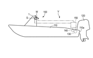
- FIG. 1 is a schematic side view of a ship V equipped with a steering device according to the present embodiment.
- FIG. 2 is a schematic plan view of the ship V shown in FIG.
- the ship V includes a steering device 100, a hull 110, and an outboard motor 120.
- the steering device 100 includes a helm device 1 having a sensor S for detecting the steering wheel W and the amount of rotation (steering angle) of the steering wheel W, an electric actuator 130 for changing the steering angle of the outboard motor 120, and an outboard motor. It includes a rudder angle sensor 140 that detects the rudder angle of 120, and a control unit 150.
- the control unit 150 is electrically connected to the helm device 1, the actuator 130, and the steering angle sensor 140.
- the outboard motor 120 includes a screw that gives a propulsive force to the ship V, and is attached to, for example, the rear wall 110a of the hull 110.
- the control unit 150 drives the actuator 130 so that the target steering angle set based on the information obtained from the sensor S and the actual steering angle of the outboard motor 120 detected by the steering angle sensor 140 match. ..
- FIG. 3 is a schematic perspective view of the helm device 1.
- the helm device 1 includes a steering shaft 2, a housing 3, a tilt base 4, a pair of tilt mechanisms 5R and 5L, and a lock mechanism 6.
- the steering shaft 2 has a long shape along the first direction X, and has a mounting portion 20 to which the steering wheel W is mounted in the vicinity of the tip portion 2a. A part of the steering shaft 2 is housed in the housing 3.
- the steering shaft 2 is rotatable about a shaft axis SX parallel to the first direction X.
- the housing 3 has a tip portion 3a in the first direction X and a rear end portion 3b on the opposite side thereof.
- the steering shaft 2 extends from the tip portion 3a.
- the housing 3 is composed of a housing base 30, a housing top 31 including a front end portion 3a, and a cover 32 including a rear end portion 3b.
- the housing base 30 and the housing top 31 are made of a metal material
- the cover 32 is made of a resin material.
- the housing base 30 has, for example, a cylindrical shape, and has a first end portion 30a in the first direction X and a second end portion 30b on the opposite side of the first end portion 30a.
- the housing top 31 is connected to the first end portion 30a by a plurality of connecting members 33, for example, bolts.
- the cover 32 is connected to the second end 30b by a plurality of connecting members, for example bolts.
- the housing top 31 has an opening 31a in the tip portion 3a for passing the steering shaft 2.
- the gap between the inner wall of the opening 31a and the steering shaft 2 is closed by the lid material 31b.
- the tilt base 4 has a first side surface 4a in the first direction X, a second side surface 4b opposite to the first side surface 4a, and an opening 4c extending from the first side surface 4a to the second side surface 4b.
- the housing 3 is passed through the opening 4c. Most of the housing 3 is located closer to the tip portion 2a of the steering shaft 2 than the first side surface 4a.
- the tilt base 4 is fixed to the mounting position by an appropriate means such as fastening with bolts in a state where the second side surface 4b is in contact with the mounting position of the helm device 1 on the hull 110, for example.
- the tilt mechanisms 5R and 5L support the housing 3 so that the housing 3 can rotate with respect to the tilt base 4 around a tilt axis TX parallel to the second direction Y that intersects the first direction X. ..
- the first direction X and the second direction Y are orthogonal to each other.
- FIG. 4 is a schematic perspective view of the helm device 1 in a state where the tilt mechanism 5R is disassembled.
- the tilt mechanism 5R includes a shaft member 50, a bracket 51, a bush 52, and a first urging member 53.
- the shaft member 50 is provided on the side portion of the housing 3 (the side portion of the housing base 30) that intersects the tilt shaft TX.
- the shaft member 50 has a cylindrical first portion 50a centered on the tilt axis TX and a circular second portion 50b centered on the tilt shaft TX.
- the diameter of the outer peripheral surface of the second portion 50b is larger than the diameter of the outer peripheral surface of the first portion 50a.
- the second portion 50b is located between the first portion 50a and the housing base 30.
- the first portion 50a and the second portion 50b are integrally formed with the housing base 30.
- the first portion 50a and the second portion 50b may be connected to the housing base 30 by appropriate means such as screwing.
- the bracket 51 has a mounting surface 51a on the tilt base 4 side and a circular hole portion 51b centered on the tilt shaft TX.
- the hole 51b is an opening that penetrates the bracket 51 in the second direction Y, but the hole 51b may be a bottomed depression.
- the inner diameter of the hole 51b is larger than the outer diameter of the first portion 50a of the shaft member 50.
- the tilt base 4 has a pedestal portion 41 on the first side surface 4a side.
- the pedestal portion 41 is provided with a pair of mounting holes 41a penetrating to the second side surface 4b.
- a female screw 51c is provided on the mounting surface 51a of the bracket 51 at a position facing the mounting holes 41a.
- the bracket 51 is connected to the tilt base 4 by bringing the mounting surface 51a into contact with the pedestal portion 41 and screwing bolts into the female threads 51c through the respective mounting holes 41a.
- the bush 52 has a cylindrical first portion 52a centered on the tilt axis TX and a cylindrical second portion 52b centered on the tilt axis TX.
- the inner diameter of the first portion 52a is larger than the outer diameter of the first portion 50a of the shaft member 50, and the outer diameter of the first portion 52a is smaller than the inner diameter of the hole portion 51b of the bracket 51.
- the outer diameter of the second portion 52b is larger than the inner diameter of the hole portion 51b.
- a first restraint portion 54a and a second restraint portion 54b protruding in the second direction Y are provided on the outer surface of the housing base 30.
- the first restraint portion 54a and the second restraint portion 54b are arranged in the circumferential direction about the tilt axis TX.
- a gap is provided between the first restraint portion 54a and the second restraint portion 54b and the second portion 50b of the shaft member 50.
- a third restraint portion 54c and a fourth restraint portion 54d projecting in the second direction Y are provided on the surface of the bracket 51 facing the housing base 30.
- the third restraint portion 54c and the fourth restraint portion 54d are arranged concentrically with the first restraint portion 54a and the second restraint portion 54b.
- the first urging member 53 is, for example, a torsion spring, and has a coil portion 53a in which a wire rod is spirally wound, and a pair of arms 53b, 53c extending from the coil portion 53a.
- a shaft member 50 is passed through the coil portion 53a.
- the coil portion 53a is located between the second portion 50b and the restraining portions 54a and 54b.
- the arm 53b is held by a holding portion 42 provided on the tilt base 4.
- the arm 53c is in contact with the lower surface (the surface on the shaft member 50 side) of the first restraining portion 54a.
- the portion of the arm 53b held by the holding portion 42 corresponds to a fixed point of the first urging member 53.
- the portion of the arm 53c that comes into contact with the first restraining portion 54a corresponds to the point of action of the first urging member 53.
- the first portion 50a of the shaft member 50 is inserted into the bush 52, and the first portion 52a of the bush 52 is inserted into the hole portion 51b of the bracket 51.
- the first portion 52a of the bush 52 is interposed between the first portion 50a of the shaft member 50 and the inner wall of the hole portion 51b.
- the second portion 52b of the bush 52 is interposed between the second portion 50b of the shaft member 50 and the peripheral edge portion of the hole portion 51b of the bracket 51.
- the tilt mechanism 5L has the same structure as the tilt mechanism 5R. As a result, the housing 3 is supported by the tilt mechanisms 5R and 5L, and is rotatable with respect to the tilt base 4 about the tilt axis TX.
- each bracket 51 projects from the tilt base 4 toward the tip portion 2a of the steering shaft 2.
- the tilt shaft TX is located between the tilt base 4 and the tip portion 2a of the steering shaft 2.
- the center of gravity of the main body of the helm device 1 including the steering shaft 2 and the housing 3 supported by the tilt mechanisms 5R and 5L is located closer to the tip portion 2a of the steering shaft 2 than the tilt shaft TX. Therefore, in a state where the housing 3 is released by the lock mechanism 6 described later, the housing 3 can rotate so that the shaft shaft SX faces downward in FIGS. 3 and 4.
- the first urging member 53 plays a role of suppressing such rotation. That is, the first urging member 53 urges the housing 3 so that the shaft shaft SX faces upward in FIGS. 3 and 4.
- FIG. 5 is a schematic partial cross-sectional view of the helm device 1 along the VV line in FIG.
- the configuration of the lock mechanism 6 will be described with reference to FIGS. 3 and 5.
- the lock mechanism 6 includes an arc portion 60 provided at the lower part of the housing 3, a lever 61, a pin 62, and a second urging member 63.
- the arc portion 60 is integrally formed with, for example, the housing base 30, and has an arc-shaped outer peripheral surface centered on the tilt axis TX.
- a plurality of slots 64 are provided on the outer peripheral surface.
- the slots 64 extend in parallel with the tilt axis TX and are arranged at regular intervals in the circumferential direction about the tilt axis TX.
- the arc portion 60 has five slots 64, but the number of slots 64 may be four or less, or six or more.
- the tilt base 4 has a pair of holding portions 65R and 65L for holding the lever 61.
- the holding portion 65R is shown in FIG. 3, and the holding portion 65L is shown in FIG.
- the shapes of the holding portions 65R and 65L are the same, and both of them protrude from the first side surface 4a at the lower part of the tilt base 4.
- the lever 61 is made of metal, for example, and is located between the holding portions 65R and 65L.
- the pin 62 is parallel to the tilt shaft TX and is passed through the holes provided in the holding portions 65R and 65L and the lever 61, respectively.
- the lever 61 is rotatably connected to the tilt base 4 about an axis parallel to the tilt axis TX.
- the lever 61 has an operating portion 61a extending downward from the vicinity of the pin 62 and an acting portion 61b extending downward from the vicinity of the pin 62 toward the arc portion 60.
- the operation unit 61a and the action unit 61b are substantially L-shaped.
- the operation unit 61a is a part for the user to manually operate (push).
- a latch 61c that can be inserted into and removed from the slot 64 is provided at the tip of the working portion 61b.
- the operation unit 61a may be covered with a cover made of, for example, resin or rubber. Such a cover may be detachable from the operation unit 61a.
- the second urging member 63 is, for example, a torsion spring, and is an arm 63b connecting a pair of coil portions 63Ra, 63La in which a wire rod is spirally wound and the coil portions 63Ra, 63La extending from the coil portions 63Ra, 63La. And an arm 63c extending from each of the coil portions 63Ra and 63La.
- the coil portion 63Ra is shown in FIG. 3, and the coil portion 63La is shown in FIG.
- a pin 62 is passed through the coil portions 63Ra and 63La.
- the arm 63b is supported by a support portion 43 provided on the tilt base 4.
- the arm 63c extending from each of the coil portions 63Ra and 63La is in contact with the back surface of the operation portion 61a.
- the portion of the arm 63b supported by the support portion 43 corresponds to a fixed point of the second urging member 63.
- the portion of each arm 63c that comes into contact with the back surface of the operating portion 61a corresponds to the point of action of the second urging member 63.
- the second urging member 63 always urges the lever 61 so that the latch 61c is pressed against the arc portion 60. As a result, when the operation unit 61a is not pressed, the state in which the latch 61c is inserted into the slot 64 is maintained as shown in FIG. At this time, the rotation of the housing 3 by the tilt mechanisms 5R and 5L is prevented.
- the lever 61 rotates around the pin 62 and the latch 61c is slotted 64. Get out of.
- the housing 3 can rotate about the tilt axis TX.
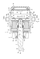
- FIG. 6 is a schematic cross-sectional view of the helm device 1 along the VI-VI line in FIG.
- FIG. 7 is a schematic cross-sectional view of the helm device 1 shown in FIG. 6 in a state where the housing 3 is disassembled.
- the first end portion 30a of the housing base 30 is inserted inside the housing top 31. Further, a part of the cover 32 is inserted inside the second end portion 30b of the housing base 30.
- the housing base 30 has a partition portion 34 inside.
- the inside of the housing 3 is divided into the first chamber C1 and the second chamber C2 by the partition portion 34.
- the first chamber C1 is a space formed by the housing base 30 and the housing top 31.
- the second chamber C2 is a space formed by the housing base 30 and the cover 32.
- the partition portion 34 has an opening 34a.
- the steering shaft 2 is passed through the opening 31a of the housing top 31 and the opening 34a of the partition portion 34.
- a magnet 21 is provided on the rear end portion 2b of the steering shaft 2 located inside the housing 3.
- the rear end portion 2b and the magnet 21 are covered with a cover 22.
- the cover 22 is connected to the partition portion 34 by a plurality of connecting members 23, for example, screws.
- the steering shaft 2 is rotatably supported by a bearing member 24 provided in the opening 31a and a bearing member 25 provided in the opening 34a.
- the steering shaft 2 is urged by the elastic member 26 in a direction protruding from the housing 3 (left in FIGS. 6 and 7). Since the elastic member 26 bends when it receives a load in the direction along the axis of the steering shaft 2, it also has a function of absorbing vibration in that direction.
- the electromagnetic brake 7 includes a rotating member 70, an electromagnet 71, an armature 72, and a disk group 73.
- the rotating member 70 is fixed to the steering shaft 2 and rotates together with the steering shaft 2.
- the electromagnet 71 is fixed inside the housing base 30 around the steering shaft 2.
- the armature 72 is arranged around the steering shaft 2 inside the housing top 31.
- the armature 72 is movable in the first direction X with respect to the steering shaft 2.
- the electromagnet 71 and the armature 72 face each other in the first direction X.
- the disc group 73 includes a plurality of rotating side discs and a plurality of fixed side discs.
- a tooth portion is formed on the inner peripheral portion of the rotating disc, and the tooth portion is fitted with a spline formed on the outer peripheral surface of the rotating member 70.
- the rotating side disc is movably held in the first direction X by the rotating member 70, and is rotated together with the rotating member 70.
- a tooth portion is formed on the outer peripheral portion of the fixed-side disk, and the tooth portion is fitted with a spline provided on the yoke of the electromagnet 71.
- the fixed-side disc is held by the yoke so as to be movable in the first direction X and non-rotatable with respect to the housing top 31.
- the rotating side disc and the fixed side disc are alternately arranged along the first direction X between the electromagnet 71 and the armature 72.
- the electromagnet 71 includes the above yoke and coil.
- the armature 72 is attracted to the yoke by the magnetic force generated when electric power is supplied to the coil, and the disk group 73 is pushed. At this time, in the disc group 73, the rotating side disc and the fixed side disc are pressed against each other, and the frictional force when rotating the steering shaft 2 increases.
- the resistance force (steering force) when operating the steering shaft 2 and the steering wheel W can be adjusted.
- the resistance force is set by the control unit 150 according to the wishes of the ship operator and the ship maneuvering situation. If it is desired to increase the resistance, the electric power supplied to the coil of the electromagnet 71 may be increased, and if it is desired to decrease the resistance, the electric power may be decreased.
- the control unit 150 may have a function of locking the steering shaft 2 so that the steering wheel W does not rotate any more when the steering wheel W rotates from the neutral position to the maximum steering angle. That is, when the steering wheel W is rotated to the starboard side or the steering side to the maximum steering wheel rotation speed, the electric power supplied by the control unit 150 to the electromagnet 71 is maximized. As a result, the magnetic force of the electromagnet 71 is maximized, and the rotating side disk and the fixed side disk in the disk group 73 are locked to each other.
- a flat plate-shaped first circuit board 81 and a second circuit board 82 orthogonal to the first direction X are arranged.
- the first circuit board 81 is fixed to a plurality of boss portions 35 provided in the partition portion 34 by, for example, a connecting member 36 which is a screw.
- the second circuit board 82 is fixed to a plurality of boss portions 37 provided on the cover 32 by, for example, a connecting member 38 which is a screw.
- the first circuit board 81 and the second circuit board 82 face each other with a gap in the first direction X.
- the above-mentioned sensor S is mounted on the first circuit board 81.
- the sensor S detects the rotation of the steering shaft 2 based on the magnetism generated by the magnet 21.
- the second circuit board 82 is mounted with a power supply circuit 83 that supplies electric power to the electrical elements of the helm device 1 such as the first circuit board 81, the electromagnetic brake 7, and the sensor S.
- the electromagnetic brake 7 and the power supply circuit 83, and the first circuit board 81 and the second circuit board 82 are connected by wiring (not shown). Further, wiring (not shown) for connection with a device such as a control unit 150 or a battery arranged outside the housing 3 is connected to the first circuit board 81 and the second circuit board 82.
- circuit boards 81 and 82 By arranging the two circuit boards 81 and 82 in the housing 3 in this way, it is possible to secure a wide space for mounting various ICs and electronic components including the sensor S and the power supply circuit 83. Moreover, if these circuit boards 81 and 82 are arranged in the first direction X, the width of the circuit boards 81, 82, the second chamber C2, the housing 3 and the like in the second direction Y can be reduced.
- the tilt axis TX is arranged at a position closer to the rear end portion 3b than the front end portion 3a of the housing 3 in the second direction Y.
- the rear end portion 2b of the steering shaft 2 located inside the housing 3 overlaps with each shaft member 50.
- the second chamber C2 and the first circuit board 81 also overlap with each shaft member 50 in the second direction Y.
- the tilt axis TX passes between the first circuit board 81 and the partition portion 34.
- the sensor S and the magnet 21 are generally located on the tilt axis TX.
- the first chamber C1 is located on the tip 3a side of the housing 3 with respect to the tilt shaft TX.
- each shaft member 50 is located closer to the rear end portion 3b of the housing 3 than the electromagnetic brake 7.
- the second circuit board 82 does not overlap with each shaft member 50 in the second direction Y, and is located on the rear end portion 3b side of the first circuit board 81.
- helm device 1 having an adjustable tilt angle of the steering shaft 2 and excellent functionality and operability.
- specific actions and effects of the helm device 1 will be illustrated.
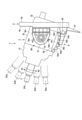
- FIG. 8 is a schematic side view of the helm device 1.
- the five slots 64 provided in the lock mechanism 6 are referred to as slots 64a, 64b, 64c, 64d, 64e as shown in FIG.
- the latch 61c is inserted in the central slot 64c.
- the tilt mechanisms 5R and 5L are used to move the steering shaft 2 and the housing 3 around the tilt shaft TX. It can be rotated in one rotation direction R1 and the opposite second rotation direction R2. Further, by inserting the latch 61c into any of the slots 64a, 64b, 64c, 64d, 64e, the rotation by the tilt mechanism 5R, 5L can be locked.
- the shaft shaft SX when the latch 61c is inserted into the slots 64a, 64b, 64c, 64d, 64e, respectively, is referred to as a shaft shaft SXa, SXb, SXc, SXd, SXe.
- the shaft shaft SXc is defined as the reference position of the steering shaft 2. Further, the angle formed by the shaft shafts SXa, SXb, SXd, and SXe with respect to the shaft shaft SXc is defined as a tilt angle.
- the tilt angle corresponds to the tilt of the steering shaft 2.
- the tilt angle of the shaft shaft SXa corresponds to the first limit angle that can be set in the first rotation direction R1
- the tilt angle of the shaft shaft SXe corresponds to the second limit angle that can be set in the second rotation direction R2.
- the tilt angle of the shaft shaft SXa is + 24 °
- the tilt angle of the shaft shaft SXb is + 12 °
- the tilt angle of the shaft shaft SXd is -12 °
- the tilt angle of the shaft shaft SXe is -24 °.
- the tilt angles of the shaft axes SXa, SXb, SXd, and SXe are not limited to this example. Further, the tilt angle does not necessarily have to be adjustable at an equal angle (12 ° in the above example).
- the tilt angle is set to the slot 64a by rotating the housing 3 in the first rotation direction R1.
- the first restraint portion 54a and the third restraint portion 54c come into contact with each other. As a result, further rotation of the housing 3 in the first rotation direction R1 is stopped.
- the rotation of the housing 3 is stopped at the positions corresponding to the slots 64a and 64e, so that the operator can easily know the limit of the tilt angle adjustment. Further, since the housing 3 is not rotated beyond the first limit angle or the second limit angle, it is possible to prevent the tilt base 4 or the hull from colliding with the housing 3.
- the first restraining portion 54a not only has a role of restraining further rotation of the housing 3 in the first rotation direction R1 at the first limit angle, but also has a role of receiving the arm 53c of the first urging member 53. As a result, the number of components of the helm device 1 can be reduced, and the assembly of the helm device 1 is facilitated.
- the center of gravity of the helm device 1 is larger than that of the tilt axis TX as described above. It is located on the tip 3a side. Even in this case, the first urging member 53 described above prevents the steering shaft 2 from tilting downward due to the weight of the housing 3 or the like in a state where the housing 3 is released from being fixed by the lock mechanism 6. ..
- the tilt axis TX is located between the tilt base 4 and the tip portion 2a of the steering shaft 2 in the first direction X. Further, the tilt axis TX is located closer to the rear end portion 3b than the front end portion 3a of the housing 3 in the first direction X. As a result, the amount of protrusion of the housing 3 to the rear of the tilt base 4 is reduced, and the degree of freedom in the structure of the hull to which the tilt base 4 is fixed is increased. In addition to the above, various suitable effects can be obtained from the present embodiment.
- the present embodiment does not limit the scope of the present invention to the configuration disclosed in the embodiment.
- the present invention can be implemented by modifying the configuration disclosed in the present embodiment into various embodiments.
- FIG. 9 is a schematic side view of the helm device 1 according to the modified example.
- the locking mechanism 6 includes a fifth restraint portion 66a and a sixth restraint portion 66b.
- the helm device 1 may further include the above-mentioned restraint portions 54a, 54b, 54c, 54d in addition to the fifth restraint portion 66a and the sixth restraint portion 66b.
- the fifth restraint portion 66a and the sixth restraint portion 66b are located at both ends of the slots 64a, 64b, 64c, 64d, 64e in the circumferential direction about the tilt axis TX, respectively.
- the fifth restraint portion 66a and the sixth restraint portion 66b project downward sufficiently longer than the portion of the arc portion 60 between the slots 64a, 64b, 64c, 64d, 64e.
- the fifth restraint portion 66a and the sixth restraint portion 66b rotate the housing 3 about the tilt axis TX even when the lever 61 is pushed and the latch 61c is separated from the arc portion 60 as much as possible. It has a length that makes contact with the latch 61c.
- the tilt angle is set to the slot 64a by rotating the housing 3 in the first rotation direction R1.
- the corresponding + 24 ° (first limit angle) is reached, the fifth restraint portion 66a and the latch 61c come into contact with each other. As a result, further rotation of the housing 3 in the first rotation direction R1 is stopped.
- the fifth restraint portion 66a and the sixth restraint portion 66b can also suppress the rotation of the housing 3 beyond the first limit angle and the second limit angle.
- Electromagnetic brake 30 ... Housing base, 31 ... Housing top, 32 ... Cover, 50 ... Shaft member, 51 ... Bracket, 52 ... Bush, 53 ... First urging member, 54a ... First restraint, 54b ... Second restraint, 54c ... Third restraint, 54d ... Fourth restraint, 60 ... Arc portion, 61 ... Lever, 61c ... Latch, 62 ... Pin, 63 ... Second urging member, 64 ... Slot, 81 ... First circuit board, 82 ... Second circuit board, 100 ... Steering device, W ... Steering wheel , S ... sensor, TX ... tilt axis, SX ... shaft axis, X ... first direction, Y ... second direction.
Landscapes
- Chemical & Material Sciences (AREA)
- Engineering & Computer Science (AREA)
- Combustion & Propulsion (AREA)
- Mechanical Engineering (AREA)
- Ocean & Marine Engineering (AREA)
- Steering Controls (AREA)
Priority Applications (2)
| Application Number | Priority Date | Filing Date | Title |
|---|---|---|---|
| EP21850257.3A EP4190684B1 (en) | 2020-07-30 | 2021-07-20 | Helm device |
| US18/160,676 US11794870B2 (en) | 2020-07-30 | 2023-01-27 | Helm device |
Applications Claiming Priority (2)
| Application Number | Priority Date | Filing Date | Title |
|---|---|---|---|
| JP2020129045A JP7203327B2 (ja) | 2020-07-30 | 2020-07-30 | ヘルム装置 |
| JP2020-129045 | 2020-07-30 |
Related Child Applications (1)
| Application Number | Title | Priority Date | Filing Date |
|---|---|---|---|
| US18/160,676 Continuation US11794870B2 (en) | 2020-07-30 | 2023-01-27 | Helm device |
Publications (1)
| Publication Number | Publication Date |
|---|---|
| WO2022024872A1 true WO2022024872A1 (ja) | 2022-02-03 |
Family
ID=80035609
Family Applications (1)
| Application Number | Title | Priority Date | Filing Date |
|---|---|---|---|
| PCT/JP2021/027123 Ceased WO2022024872A1 (ja) | 2020-07-30 | 2021-07-20 | ヘルム装置 |
Country Status (4)
| Country | Link |
|---|---|
| US (1) | US11794870B2 (https=) |
| EP (1) | EP4190684B1 (https=) |
| JP (1) | JP7203327B2 (https=) |
| WO (1) | WO2022024872A1 (https=) |
Families Citing this family (1)
| Publication number | Priority date | Publication date | Assignee | Title |
|---|---|---|---|---|
| WO2025050293A1 (zh) * | 2023-09-05 | 2025-03-13 | 广东逸动科技有限公司 | 电动转向装置及其控制方法、推进器和水域可移动设备 |
Citations (9)
| Publication number | Priority date | Publication date | Assignee | Title |
|---|---|---|---|---|
| JPH10236393A (ja) * | 1996-11-29 | 1998-09-08 | Yamaha Motor Co Ltd | 小型船艇のステアリング装置 |
| JPH11222197A (ja) * | 1998-02-05 | 1999-08-17 | Marooru Kk | 手動油圧操舵装置 |
| JP2000043794A (ja) * | 1998-07-29 | 2000-02-15 | Maroole Kk | 手動油圧操舵装置 |
| JP2005104281A (ja) * | 2003-09-30 | 2005-04-21 | Marol Ltd | 手動油圧操舵装置のチルト機構 |
| JP2006069464A (ja) * | 2004-09-06 | 2006-03-16 | Kawasaki Heavy Ind Ltd | 小型滑走艇の操縦装置 |
| JP2007320549A (ja) * | 2006-06-01 | 2007-12-13 | Teleflex Canada Inc | チルトステアリング機構 |
| JP2014054961A (ja) * | 2012-09-13 | 2014-03-27 | Nhk Spring Co Ltd | 船舶のヘルム装置 |
| JP2016147627A (ja) * | 2015-02-13 | 2016-08-18 | 本田技研工業株式会社 | チルトステアリング装置 |
| US10011340B2 (en) | 2016-02-19 | 2018-07-03 | Ultraflex S.P.A. | Streering device for marine vessels |
Family Cites Families (3)
| Publication number | Priority date | Publication date | Assignee | Title |
|---|---|---|---|---|
| US2826090A (en) * | 1955-01-27 | 1958-03-11 | Supreme Foundry Inc | Boat steering controls |
| NO172225C (no) * | 1991-03-07 | 1993-06-23 | Steering Control As | Anordning ved styresystem |
| CA2438981C (en) * | 2003-08-29 | 2010-01-12 | Teleflex Canada Incorporated | Steer by wire helm |
-
2020
- 2020-07-30 JP JP2020129045A patent/JP7203327B2/ja active Active
-
2021
- 2021-07-20 WO PCT/JP2021/027123 patent/WO2022024872A1/ja not_active Ceased
- 2021-07-20 EP EP21850257.3A patent/EP4190684B1/en active Active
-
2023
- 2023-01-27 US US18/160,676 patent/US11794870B2/en active Active
Patent Citations (9)
| Publication number | Priority date | Publication date | Assignee | Title |
|---|---|---|---|---|
| JPH10236393A (ja) * | 1996-11-29 | 1998-09-08 | Yamaha Motor Co Ltd | 小型船艇のステアリング装置 |
| JPH11222197A (ja) * | 1998-02-05 | 1999-08-17 | Marooru Kk | 手動油圧操舵装置 |
| JP2000043794A (ja) * | 1998-07-29 | 2000-02-15 | Maroole Kk | 手動油圧操舵装置 |
| JP2005104281A (ja) * | 2003-09-30 | 2005-04-21 | Marol Ltd | 手動油圧操舵装置のチルト機構 |
| JP2006069464A (ja) * | 2004-09-06 | 2006-03-16 | Kawasaki Heavy Ind Ltd | 小型滑走艇の操縦装置 |
| JP2007320549A (ja) * | 2006-06-01 | 2007-12-13 | Teleflex Canada Inc | チルトステアリング機構 |
| JP2014054961A (ja) * | 2012-09-13 | 2014-03-27 | Nhk Spring Co Ltd | 船舶のヘルム装置 |
| JP2016147627A (ja) * | 2015-02-13 | 2016-08-18 | 本田技研工業株式会社 | チルトステアリング装置 |
| US10011340B2 (en) | 2016-02-19 | 2018-07-03 | Ultraflex S.P.A. | Streering device for marine vessels |
Non-Patent Citations (1)
| Title |
|---|
| See also references of EP4190684A4 |
Also Published As
| Publication number | Publication date |
|---|---|
| EP4190684A1 (en) | 2023-06-07 |
| US20230166822A1 (en) | 2023-06-01 |
| JP2022025881A (ja) | 2022-02-10 |
| US11794870B2 (en) | 2023-10-24 |
| EP4190684B1 (en) | 2026-01-21 |
| EP4190684A4 (en) | 2024-03-20 |
| JP7203327B2 (ja) | 2023-01-13 |
Similar Documents
| Publication | Publication Date | Title |
|---|---|---|
| US6429849B1 (en) | Haptic feedback joystick | |
| US8281728B2 (en) | Steering apparatus for outboard motor | |
| EP3000718B1 (en) | Electrical propulsion device | |
| US9389634B2 (en) | Helm device for boat | |
| US7242390B2 (en) | Electric switch | |
| JP2020090219A (ja) | 反力発生装置、及び操舵装置 | |
| US20010035689A1 (en) | Actuation device with actuator and brake | |
| JP2018062254A (ja) | シフト装置 | |
| JP7444122B2 (ja) | ステアリングハンドル | |
| WO2022024872A1 (ja) | ヘルム装置 | |
| JP4678254B2 (ja) | ステアバイワイヤシステム | |
| JP4248390B2 (ja) | ステアリング操作装置 | |
| KR101601544B1 (ko) | 자동차의 미러 액추에이터 | |
| JP3423446B2 (ja) | 駆動装置および飛翔体の操舵装置 | |
| JP6807258B2 (ja) | 操作装置 | |
| JP7854882B2 (ja) | シフト装置 | |
| JP2021038672A (ja) | スロットルグリップ装置 | |
| BR112012017156B1 (pt) | dispositivo para controlar um aparelho integrado | |
| JP2004108301A (ja) | 最高車速制限装置 | |
| JP2026018650A (ja) | 船外機の操作装置 | |
| WO2023090047A1 (ja) | 機関制御装置 | |
| JP2021051865A (ja) | 操作装置 | |
| JP2021172267A (ja) | ステアリングコラム装置 | |
| JPH01227503A (ja) | 反射鏡アンテナ装置 |
Legal Events
| Date | Code | Title | Description |
|---|---|---|---|
| 121 | Ep: the epo has been informed by wipo that ep was designated in this application |
Ref document number: 21850257 Country of ref document: EP Kind code of ref document: A1 |
|
| NENP | Non-entry into the national phase |
Ref country code: DE |
|
| ENP | Entry into the national phase |
Ref document number: 2021850257 Country of ref document: EP Effective date: 20230228 |
|
| WWG | Wipo information: grant in national office |
Ref document number: 2021850257 Country of ref document: EP |