WO2022024872A1 - Helm device - Google Patents
Helm device Download PDFInfo
- Publication number
- WO2022024872A1 WO2022024872A1 PCT/JP2021/027123 JP2021027123W WO2022024872A1 WO 2022024872 A1 WO2022024872 A1 WO 2022024872A1 JP 2021027123 W JP2021027123 W JP 2021027123W WO 2022024872 A1 WO2022024872 A1 WO 2022024872A1
- Authority
- WO
- WIPO (PCT)
- Prior art keywords
- housing
- tilt
- steering shaft
- base
- shaft
- Prior art date
Links
- 241000380131 Ammophila arenaria Species 0.000 title claims abstract description 51
- 230000007246 mechanism Effects 0.000 claims abstract description 50
- 230000002093 peripheral effect Effects 0.000 claims description 12
- 238000005192 partition Methods 0.000 description 7
- 230000000452 restraining effect Effects 0.000 description 5
- NJPPVKZQTLUDBO-UHFFFAOYSA-N novaluron Chemical compound C1=C(Cl)C(OC(F)(F)C(OC(F)(F)F)F)=CC=C1NC(=O)NC(=O)C1=C(F)C=CC=C1F NJPPVKZQTLUDBO-UHFFFAOYSA-N 0.000 description 3
- 230000000694 effects Effects 0.000 description 2
- 230000005484 gravity Effects 0.000 description 2
- 239000000463 material Substances 0.000 description 2
- 239000011347 resin Substances 0.000 description 2
- 229920005989 resin Polymers 0.000 description 2
- 230000003247 decreasing effect Effects 0.000 description 1
- 230000005389 magnetism Effects 0.000 description 1
- 239000002184 metal Substances 0.000 description 1
- 239000007769 metal material Substances 0.000 description 1
- 230000007935 neutral effect Effects 0.000 description 1
- 230000000149 penetrating effect Effects 0.000 description 1
- 230000001141 propulsive effect Effects 0.000 description 1
Images


Classifications
-
- B—PERFORMING OPERATIONS; TRANSPORTING
- B63—SHIPS OR OTHER WATERBORNE VESSELS; RELATED EQUIPMENT
- B63H—MARINE PROPULSION OR STEERING
- B63H20/00—Outboard propulsion units, e.g. outboard motors or Z-drives; Arrangements thereof on vessels
- B63H20/08—Means enabling movement of the position of the propulsion element, e.g. for trim, tilt or steering; Control of trim or tilt
- B63H20/10—Means enabling trim or tilt, or lifting of the propulsion element when an obstruction is hit; Control of trim or tilt
-
- B—PERFORMING OPERATIONS; TRANSPORTING
- B63—SHIPS OR OTHER WATERBORNE VESSELS; RELATED EQUIPMENT
- B63H—MARINE PROPULSION OR STEERING
- B63H25/00—Steering; Slowing-down otherwise than by use of propulsive elements; Dynamic anchoring, i.e. positioning vessels by means of main or auxiliary propulsive elements
- B63H25/02—Initiating means for steering, for slowing down, otherwise than by use of propulsive elements, or for dynamic anchoring
-
- B—PERFORMING OPERATIONS; TRANSPORTING
- B63—SHIPS OR OTHER WATERBORNE VESSELS; RELATED EQUIPMENT
- B63H—MARINE PROPULSION OR STEERING
- B63H20/00—Outboard propulsion units, e.g. outboard motors or Z-drives; Arrangements thereof on vessels
- B63H20/08—Means enabling movement of the position of the propulsion element, e.g. for trim, tilt or steering; Control of trim or tilt
- B63H20/12—Means enabling steering
-
- B—PERFORMING OPERATIONS; TRANSPORTING
- B63—SHIPS OR OTHER WATERBORNE VESSELS; RELATED EQUIPMENT
- B63H—MARINE PROPULSION OR STEERING
- B63H25/00—Steering; Slowing-down otherwise than by use of propulsive elements; Dynamic anchoring, i.e. positioning vessels by means of main or auxiliary propulsive elements
- B63H25/02—Initiating means for steering, for slowing down, otherwise than by use of propulsive elements, or for dynamic anchoring
- B63H2025/022—Steering wheels; Posts for steering wheels
Definitions
- the present invention relates to a helm device used for steering a ship.
- a steering device for changing the steering angle of an outboard motor
- a steering device that transmits the rotation of the steering shaft connected to the steering wheel (helm) to the actuator of the outboard motor by a hydraulic pipe or a push-pull cable
- an electric steering device that detects the rotation of the steering shaft by a sensor and drives the actuator of the outboard motor based on the electric signal output by the sensor.
- the steering shaft is tilted at a predetermined tilt angle with respect to the horizontal direction.
- the tilt angle of the helm device including the steering shaft can be adjusted.
- the steering device disclosed in Patent Document 1 is known.
- one of the objects of the present invention is to provide a helm device in which the tilt angle of the steering shaft can be adjusted and which is excellent in functionality and operability.
- the helm device is parallel to a steering shaft extending in the first direction, a housing accommodating a part of the steering shaft, a tilt base attached to a hull, and a second direction intersecting the first direction.
- a lock mechanism for fixing the angle of the steering shaft with respect to the tilt base.
- Each of the pair of tilt mechanisms is a bracket having a shaft member protruding from a side portion of the housing intersecting the tilt shaft and a hole provided in the tilt base into which the shaft member is rotatably inserted. And a bush arranged between the outer peripheral surface of the shaft member and the inner peripheral surface of the hole portion.
- the tilt base has an opening, the housing is passed through the opening, the bracket projects from the tilt base toward the tip of the steering shaft, and the tilt shaft tilts in the first direction. It may be located between the base and the tip of the steering shaft.
- Each of the pair of tilt mechanisms may further include a first urging member that urges the housing in a predetermined rotation direction about the tilt axis.
- the first urging member extends from the coil portion through which the shaft member is passed, an arm on the fixed point side extended from the coil portion and supported by the tilt base, and the coil portion. It may have an arm on the action point side supported by the housing.
- the locking mechanism may include a plurality of slots arranged in the circumferential direction about the tilt axis on the outer surface of the housing, and a lever having a latch that can be inserted into the plurality of slots.
- the rotation of the housing by the pair of tilt mechanisms may be stopped by inserting the latch into any of the plurality of slots.
- the locking mechanism urges a pin that rotatably connects the lever to the tilt base about an axis parallel to the tilt axis and the lever so that the latch is pressed against the plurality of slots.
- a second urging member may be further provided.
- the second urging member includes a coil portion through which the pin is passed, an arm on the fixed point side extending from the coil portion and supported by the tilt base, and a lever extending from the coil portion. It may have an arm on the side of the point of action supported by.
- Each of the pair of tilt mechanisms is provided on the housing around the shaft member, and is provided on the bracket, the first restraint portion and the second restraint portion arranged in the circumferential direction about the tilt shaft.
- a third restraint portion and a fourth restraint portion arranged concentrically with the first restraint portion and the second restraint portion may be further provided.
- the lock mechanism may further include a fifth restraint portion and a sixth restraint portion located at both ends of the plurality of slots in the circumferential direction about the tilt axis. Further, in a state where the latch is retracted from the plurality of slots, the tilt of the steering shaft reaches the first limit angle by rotating the housing in the first rotation direction about the tilt axis. In this case, in a state where the fifth restraint portion and the latch are in contact with each other to stop further rotation of the housing in the first rotation direction and the latch is retracted from the plurality of slots, the first rotation is performed. When the inclination of the steering shaft reaches the second limit angle by rotating the housing in the second rotation direction opposite to the moving direction, the sixth restraint portion and the latch come into contact with each other and the housing is said. Further rotation in the second rotation direction may be stopped.
- the end of the steering shaft located inside the housing may overlap the shaft member in a direction parallel to the tilt axis.
- the helm device may further include an electromagnetic brake that is housed in the housing and imparts resistance to the steering shaft.
- the housing may have a tip portion on which the steering shaft extends and a rear end portion located on the opposite side of the tip portion in the first direction. Further, in the first direction, the shaft member may be located closer to the rear end portion than the electromagnetic brake.
- the helm device further includes a first circuit board on which a sensor for detecting rotation of the steering shaft is mounted, and a second circuit board on which a power supply circuit for supplying electric power to the first circuit board is mounted. You may. Further, in the second direction, the first circuit board may overlap with the shaft member, and in the first direction, the second circuit board may be located between the first circuit board and the rear end portion. ..
- the housing has a housing base having a first end portion in the first direction, a second end portion on the opposite side of the first end portion, and the shaft member of the pair of tilt mechanisms, and the housing base.
- a housing top connected to the first end portion of the housing top and provided with an opening for passing the steering shaft, and a cover connected to the second end portion of the housing base may be provided.
- the housing base and the housing top form a first chamber for accommodating a part of the steering shaft and the electromagnetic brake
- the housing base and the cover are the first circuit board and the second circuit board.
- a second chamber accommodating a circuit board may be formed, and the second chamber may overlap with the shaft member in the second direction.
- a helm device having an adjustable tilt angle of the steering shaft and excellent functionality and operability.
- FIG. 1 is a schematic side view of a ship equipped with a steering device according to an embodiment.
- FIG. 2 is a schematic plan view of the ship shown in FIG.
- FIG. 3 is a schematic perspective view of the helm device according to the embodiment.
- FIG. 4 is a schematic perspective view of the helm device in a state where the tilt mechanism shown in FIG. 3 is disassembled.
- FIG. 5 is a schematic partial cross-sectional view of the helm device along the VV line in FIG.
- FIG. 6 is a schematic cross-sectional view of the helm device along the VI-VI line in FIG.
- FIG. 7 is a schematic cross-sectional view of the helm device shown in FIG. 6 in a state where the housing is disassembled.
- FIG. 8 is a schematic side view of the helm device shown in FIG.
- FIG. 9 is a schematic side view of the helm device according to the modified example.
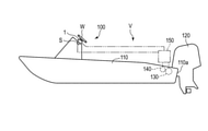
- FIG. 1 is a schematic side view of a ship V equipped with a steering device according to the present embodiment.
- FIG. 2 is a schematic plan view of the ship V shown in FIG.
- the ship V includes a steering device 100, a hull 110, and an outboard motor 120.
- the steering device 100 includes a helm device 1 having a sensor S for detecting the steering wheel W and the amount of rotation (steering angle) of the steering wheel W, an electric actuator 130 for changing the steering angle of the outboard motor 120, and an outboard motor. It includes a rudder angle sensor 140 that detects the rudder angle of 120, and a control unit 150.
- the control unit 150 is electrically connected to the helm device 1, the actuator 130, and the steering angle sensor 140.
- the outboard motor 120 includes a screw that gives a propulsive force to the ship V, and is attached to, for example, the rear wall 110a of the hull 110.
- the control unit 150 drives the actuator 130 so that the target steering angle set based on the information obtained from the sensor S and the actual steering angle of the outboard motor 120 detected by the steering angle sensor 140 match. ..
- FIG. 3 is a schematic perspective view of the helm device 1.
- the helm device 1 includes a steering shaft 2, a housing 3, a tilt base 4, a pair of tilt mechanisms 5R and 5L, and a lock mechanism 6.
- the steering shaft 2 has a long shape along the first direction X, and has a mounting portion 20 to which the steering wheel W is mounted in the vicinity of the tip portion 2a. A part of the steering shaft 2 is housed in the housing 3.
- the steering shaft 2 is rotatable about a shaft axis SX parallel to the first direction X.
- the housing 3 has a tip portion 3a in the first direction X and a rear end portion 3b on the opposite side thereof.
- the steering shaft 2 extends from the tip portion 3a.
- the housing 3 is composed of a housing base 30, a housing top 31 including a front end portion 3a, and a cover 32 including a rear end portion 3b.
- the housing base 30 and the housing top 31 are made of a metal material
- the cover 32 is made of a resin material.
- the housing base 30 has, for example, a cylindrical shape, and has a first end portion 30a in the first direction X and a second end portion 30b on the opposite side of the first end portion 30a.
- the housing top 31 is connected to the first end portion 30a by a plurality of connecting members 33, for example, bolts.
- the cover 32 is connected to the second end 30b by a plurality of connecting members, for example bolts.
- the housing top 31 has an opening 31a in the tip portion 3a for passing the steering shaft 2.
- the gap between the inner wall of the opening 31a and the steering shaft 2 is closed by the lid material 31b.
- the tilt base 4 has a first side surface 4a in the first direction X, a second side surface 4b opposite to the first side surface 4a, and an opening 4c extending from the first side surface 4a to the second side surface 4b.
- the housing 3 is passed through the opening 4c. Most of the housing 3 is located closer to the tip portion 2a of the steering shaft 2 than the first side surface 4a.
- the tilt base 4 is fixed to the mounting position by an appropriate means such as fastening with bolts in a state where the second side surface 4b is in contact with the mounting position of the helm device 1 on the hull 110, for example.
- the tilt mechanisms 5R and 5L support the housing 3 so that the housing 3 can rotate with respect to the tilt base 4 around a tilt axis TX parallel to the second direction Y that intersects the first direction X. ..
- the first direction X and the second direction Y are orthogonal to each other.
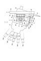
- FIG. 4 is a schematic perspective view of the helm device 1 in a state where the tilt mechanism 5R is disassembled.
- the tilt mechanism 5R includes a shaft member 50, a bracket 51, a bush 52, and a first urging member 53.
- the shaft member 50 is provided on the side portion of the housing 3 (the side portion of the housing base 30) that intersects the tilt shaft TX.
- the shaft member 50 has a cylindrical first portion 50a centered on the tilt axis TX and a circular second portion 50b centered on the tilt shaft TX.
- the diameter of the outer peripheral surface of the second portion 50b is larger than the diameter of the outer peripheral surface of the first portion 50a.
- the second portion 50b is located between the first portion 50a and the housing base 30.
- the first portion 50a and the second portion 50b are integrally formed with the housing base 30.
- the first portion 50a and the second portion 50b may be connected to the housing base 30 by appropriate means such as screwing.
- the bracket 51 has a mounting surface 51a on the tilt base 4 side and a circular hole portion 51b centered on the tilt shaft TX.
- the hole 51b is an opening that penetrates the bracket 51 in the second direction Y, but the hole 51b may be a bottomed depression.
- the inner diameter of the hole 51b is larger than the outer diameter of the first portion 50a of the shaft member 50.
- the tilt base 4 has a pedestal portion 41 on the first side surface 4a side.
- the pedestal portion 41 is provided with a pair of mounting holes 41a penetrating to the second side surface 4b.
- a female screw 51c is provided on the mounting surface 51a of the bracket 51 at a position facing the mounting holes 41a.
- the bracket 51 is connected to the tilt base 4 by bringing the mounting surface 51a into contact with the pedestal portion 41 and screwing bolts into the female threads 51c through the respective mounting holes 41a.
- the bush 52 has a cylindrical first portion 52a centered on the tilt axis TX and a cylindrical second portion 52b centered on the tilt axis TX.
- the inner diameter of the first portion 52a is larger than the outer diameter of the first portion 50a of the shaft member 50, and the outer diameter of the first portion 52a is smaller than the inner diameter of the hole portion 51b of the bracket 51.
- the outer diameter of the second portion 52b is larger than the inner diameter of the hole portion 51b.
- a first restraint portion 54a and a second restraint portion 54b protruding in the second direction Y are provided on the outer surface of the housing base 30.
- the first restraint portion 54a and the second restraint portion 54b are arranged in the circumferential direction about the tilt axis TX.
- a gap is provided between the first restraint portion 54a and the second restraint portion 54b and the second portion 50b of the shaft member 50.
- a third restraint portion 54c and a fourth restraint portion 54d projecting in the second direction Y are provided on the surface of the bracket 51 facing the housing base 30.
- the third restraint portion 54c and the fourth restraint portion 54d are arranged concentrically with the first restraint portion 54a and the second restraint portion 54b.
- the first urging member 53 is, for example, a torsion spring, and has a coil portion 53a in which a wire rod is spirally wound, and a pair of arms 53b, 53c extending from the coil portion 53a.
- a shaft member 50 is passed through the coil portion 53a.
- the coil portion 53a is located between the second portion 50b and the restraining portions 54a and 54b.
- the arm 53b is held by a holding portion 42 provided on the tilt base 4.
- the arm 53c is in contact with the lower surface (the surface on the shaft member 50 side) of the first restraining portion 54a.
- the portion of the arm 53b held by the holding portion 42 corresponds to a fixed point of the first urging member 53.
- the portion of the arm 53c that comes into contact with the first restraining portion 54a corresponds to the point of action of the first urging member 53.
- the first portion 50a of the shaft member 50 is inserted into the bush 52, and the first portion 52a of the bush 52 is inserted into the hole portion 51b of the bracket 51.
- the first portion 52a of the bush 52 is interposed between the first portion 50a of the shaft member 50 and the inner wall of the hole portion 51b.
- the second portion 52b of the bush 52 is interposed between the second portion 50b of the shaft member 50 and the peripheral edge portion of the hole portion 51b of the bracket 51.
- the tilt mechanism 5L has the same structure as the tilt mechanism 5R. As a result, the housing 3 is supported by the tilt mechanisms 5R and 5L, and is rotatable with respect to the tilt base 4 about the tilt axis TX.
- each bracket 51 projects from the tilt base 4 toward the tip portion 2a of the steering shaft 2.
- the tilt shaft TX is located between the tilt base 4 and the tip portion 2a of the steering shaft 2.
- the center of gravity of the main body of the helm device 1 including the steering shaft 2 and the housing 3 supported by the tilt mechanisms 5R and 5L is located closer to the tip portion 2a of the steering shaft 2 than the tilt shaft TX. Therefore, in a state where the housing 3 is released by the lock mechanism 6 described later, the housing 3 can rotate so that the shaft shaft SX faces downward in FIGS. 3 and 4.
- the first urging member 53 plays a role of suppressing such rotation. That is, the first urging member 53 urges the housing 3 so that the shaft shaft SX faces upward in FIGS. 3 and 4.
- FIG. 5 is a schematic partial cross-sectional view of the helm device 1 along the VV line in FIG.
- the configuration of the lock mechanism 6 will be described with reference to FIGS. 3 and 5.
- the lock mechanism 6 includes an arc portion 60 provided at the lower part of the housing 3, a lever 61, a pin 62, and a second urging member 63.
- the arc portion 60 is integrally formed with, for example, the housing base 30, and has an arc-shaped outer peripheral surface centered on the tilt axis TX.
- a plurality of slots 64 are provided on the outer peripheral surface.
- the slots 64 extend in parallel with the tilt axis TX and are arranged at regular intervals in the circumferential direction about the tilt axis TX.
- the arc portion 60 has five slots 64, but the number of slots 64 may be four or less, or six or more.
- the tilt base 4 has a pair of holding portions 65R and 65L for holding the lever 61.
- the holding portion 65R is shown in FIG. 3, and the holding portion 65L is shown in FIG.
- the shapes of the holding portions 65R and 65L are the same, and both of them protrude from the first side surface 4a at the lower part of the tilt base 4.
- the lever 61 is made of metal, for example, and is located between the holding portions 65R and 65L.
- the pin 62 is parallel to the tilt shaft TX and is passed through the holes provided in the holding portions 65R and 65L and the lever 61, respectively.
- the lever 61 is rotatably connected to the tilt base 4 about an axis parallel to the tilt axis TX.
- the lever 61 has an operating portion 61a extending downward from the vicinity of the pin 62 and an acting portion 61b extending downward from the vicinity of the pin 62 toward the arc portion 60.
- the operation unit 61a and the action unit 61b are substantially L-shaped.
- the operation unit 61a is a part for the user to manually operate (push).
- a latch 61c that can be inserted into and removed from the slot 64 is provided at the tip of the working portion 61b.
- the operation unit 61a may be covered with a cover made of, for example, resin or rubber. Such a cover may be detachable from the operation unit 61a.
- the second urging member 63 is, for example, a torsion spring, and is an arm 63b connecting a pair of coil portions 63Ra, 63La in which a wire rod is spirally wound and the coil portions 63Ra, 63La extending from the coil portions 63Ra, 63La. And an arm 63c extending from each of the coil portions 63Ra and 63La.
- the coil portion 63Ra is shown in FIG. 3, and the coil portion 63La is shown in FIG.
- a pin 62 is passed through the coil portions 63Ra and 63La.
- the arm 63b is supported by a support portion 43 provided on the tilt base 4.
- the arm 63c extending from each of the coil portions 63Ra and 63La is in contact with the back surface of the operation portion 61a.
- the portion of the arm 63b supported by the support portion 43 corresponds to a fixed point of the second urging member 63.
- the portion of each arm 63c that comes into contact with the back surface of the operating portion 61a corresponds to the point of action of the second urging member 63.
- the second urging member 63 always urges the lever 61 so that the latch 61c is pressed against the arc portion 60. As a result, when the operation unit 61a is not pressed, the state in which the latch 61c is inserted into the slot 64 is maintained as shown in FIG. At this time, the rotation of the housing 3 by the tilt mechanisms 5R and 5L is prevented.
- the lever 61 rotates around the pin 62 and the latch 61c is slotted 64. Get out of.
- the housing 3 can rotate about the tilt axis TX.
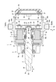
- FIG. 6 is a schematic cross-sectional view of the helm device 1 along the VI-VI line in FIG.
- FIG. 7 is a schematic cross-sectional view of the helm device 1 shown in FIG. 6 in a state where the housing 3 is disassembled.
- the first end portion 30a of the housing base 30 is inserted inside the housing top 31. Further, a part of the cover 32 is inserted inside the second end portion 30b of the housing base 30.
- the housing base 30 has a partition portion 34 inside.
- the inside of the housing 3 is divided into the first chamber C1 and the second chamber C2 by the partition portion 34.
- the first chamber C1 is a space formed by the housing base 30 and the housing top 31.
- the second chamber C2 is a space formed by the housing base 30 and the cover 32.
- the partition portion 34 has an opening 34a.
- the steering shaft 2 is passed through the opening 31a of the housing top 31 and the opening 34a of the partition portion 34.
- a magnet 21 is provided on the rear end portion 2b of the steering shaft 2 located inside the housing 3.
- the rear end portion 2b and the magnet 21 are covered with a cover 22.
- the cover 22 is connected to the partition portion 34 by a plurality of connecting members 23, for example, screws.
- the steering shaft 2 is rotatably supported by a bearing member 24 provided in the opening 31a and a bearing member 25 provided in the opening 34a.
- the steering shaft 2 is urged by the elastic member 26 in a direction protruding from the housing 3 (left in FIGS. 6 and 7). Since the elastic member 26 bends when it receives a load in the direction along the axis of the steering shaft 2, it also has a function of absorbing vibration in that direction.
- the electromagnetic brake 7 includes a rotating member 70, an electromagnet 71, an armature 72, and a disk group 73.
- the rotating member 70 is fixed to the steering shaft 2 and rotates together with the steering shaft 2.
- the electromagnet 71 is fixed inside the housing base 30 around the steering shaft 2.
- the armature 72 is arranged around the steering shaft 2 inside the housing top 31.
- the armature 72 is movable in the first direction X with respect to the steering shaft 2.
- the electromagnet 71 and the armature 72 face each other in the first direction X.
- the disc group 73 includes a plurality of rotating side discs and a plurality of fixed side discs.
- a tooth portion is formed on the inner peripheral portion of the rotating disc, and the tooth portion is fitted with a spline formed on the outer peripheral surface of the rotating member 70.
- the rotating side disc is movably held in the first direction X by the rotating member 70, and is rotated together with the rotating member 70.
- a tooth portion is formed on the outer peripheral portion of the fixed-side disk, and the tooth portion is fitted with a spline provided on the yoke of the electromagnet 71.
- the fixed-side disc is held by the yoke so as to be movable in the first direction X and non-rotatable with respect to the housing top 31.
- the rotating side disc and the fixed side disc are alternately arranged along the first direction X between the electromagnet 71 and the armature 72.
- the electromagnet 71 includes the above yoke and coil.
- the armature 72 is attracted to the yoke by the magnetic force generated when electric power is supplied to the coil, and the disk group 73 is pushed. At this time, in the disc group 73, the rotating side disc and the fixed side disc are pressed against each other, and the frictional force when rotating the steering shaft 2 increases.
- the resistance force (steering force) when operating the steering shaft 2 and the steering wheel W can be adjusted.
- the resistance force is set by the control unit 150 according to the wishes of the ship operator and the ship maneuvering situation. If it is desired to increase the resistance, the electric power supplied to the coil of the electromagnet 71 may be increased, and if it is desired to decrease the resistance, the electric power may be decreased.
- the control unit 150 may have a function of locking the steering shaft 2 so that the steering wheel W does not rotate any more when the steering wheel W rotates from the neutral position to the maximum steering angle. That is, when the steering wheel W is rotated to the starboard side or the steering side to the maximum steering wheel rotation speed, the electric power supplied by the control unit 150 to the electromagnet 71 is maximized. As a result, the magnetic force of the electromagnet 71 is maximized, and the rotating side disk and the fixed side disk in the disk group 73 are locked to each other.
- a flat plate-shaped first circuit board 81 and a second circuit board 82 orthogonal to the first direction X are arranged.
- the first circuit board 81 is fixed to a plurality of boss portions 35 provided in the partition portion 34 by, for example, a connecting member 36 which is a screw.
- the second circuit board 82 is fixed to a plurality of boss portions 37 provided on the cover 32 by, for example, a connecting member 38 which is a screw.
- the first circuit board 81 and the second circuit board 82 face each other with a gap in the first direction X.
- the above-mentioned sensor S is mounted on the first circuit board 81.
- the sensor S detects the rotation of the steering shaft 2 based on the magnetism generated by the magnet 21.
- the second circuit board 82 is mounted with a power supply circuit 83 that supplies electric power to the electrical elements of the helm device 1 such as the first circuit board 81, the electromagnetic brake 7, and the sensor S.
- the electromagnetic brake 7 and the power supply circuit 83, and the first circuit board 81 and the second circuit board 82 are connected by wiring (not shown). Further, wiring (not shown) for connection with a device such as a control unit 150 or a battery arranged outside the housing 3 is connected to the first circuit board 81 and the second circuit board 82.
- circuit boards 81 and 82 By arranging the two circuit boards 81 and 82 in the housing 3 in this way, it is possible to secure a wide space for mounting various ICs and electronic components including the sensor S and the power supply circuit 83. Moreover, if these circuit boards 81 and 82 are arranged in the first direction X, the width of the circuit boards 81, 82, the second chamber C2, the housing 3 and the like in the second direction Y can be reduced.
- the tilt axis TX is arranged at a position closer to the rear end portion 3b than the front end portion 3a of the housing 3 in the second direction Y.
- the rear end portion 2b of the steering shaft 2 located inside the housing 3 overlaps with each shaft member 50.
- the second chamber C2 and the first circuit board 81 also overlap with each shaft member 50 in the second direction Y.
- the tilt axis TX passes between the first circuit board 81 and the partition portion 34.
- the sensor S and the magnet 21 are generally located on the tilt axis TX.
- the first chamber C1 is located on the tip 3a side of the housing 3 with respect to the tilt shaft TX.
- each shaft member 50 is located closer to the rear end portion 3b of the housing 3 than the electromagnetic brake 7.
- the second circuit board 82 does not overlap with each shaft member 50 in the second direction Y, and is located on the rear end portion 3b side of the first circuit board 81.
- helm device 1 having an adjustable tilt angle of the steering shaft 2 and excellent functionality and operability.
- specific actions and effects of the helm device 1 will be illustrated.
- FIG. 8 is a schematic side view of the helm device 1.
- the five slots 64 provided in the lock mechanism 6 are referred to as slots 64a, 64b, 64c, 64d, 64e as shown in FIG.
- the latch 61c is inserted in the central slot 64c.
- the tilt mechanisms 5R and 5L are used to move the steering shaft 2 and the housing 3 around the tilt shaft TX. It can be rotated in one rotation direction R1 and the opposite second rotation direction R2. Further, by inserting the latch 61c into any of the slots 64a, 64b, 64c, 64d, 64e, the rotation by the tilt mechanism 5R, 5L can be locked.
- the shaft shaft SX when the latch 61c is inserted into the slots 64a, 64b, 64c, 64d, 64e, respectively, is referred to as a shaft shaft SXa, SXb, SXc, SXd, SXe.
- the shaft shaft SXc is defined as the reference position of the steering shaft 2. Further, the angle formed by the shaft shafts SXa, SXb, SXd, and SXe with respect to the shaft shaft SXc is defined as a tilt angle.
- the tilt angle corresponds to the tilt of the steering shaft 2.
- the tilt angle of the shaft shaft SXa corresponds to the first limit angle that can be set in the first rotation direction R1
- the tilt angle of the shaft shaft SXe corresponds to the second limit angle that can be set in the second rotation direction R2.
- the tilt angle of the shaft shaft SXa is + 24 °
- the tilt angle of the shaft shaft SXb is + 12 °
- the tilt angle of the shaft shaft SXd is -12 °
- the tilt angle of the shaft shaft SXe is -24 °.
- the tilt angles of the shaft axes SXa, SXb, SXd, and SXe are not limited to this example. Further, the tilt angle does not necessarily have to be adjustable at an equal angle (12 ° in the above example).
- the tilt angle is set to the slot 64a by rotating the housing 3 in the first rotation direction R1.
- the first restraint portion 54a and the third restraint portion 54c come into contact with each other. As a result, further rotation of the housing 3 in the first rotation direction R1 is stopped.
- the rotation of the housing 3 is stopped at the positions corresponding to the slots 64a and 64e, so that the operator can easily know the limit of the tilt angle adjustment. Further, since the housing 3 is not rotated beyond the first limit angle or the second limit angle, it is possible to prevent the tilt base 4 or the hull from colliding with the housing 3.
- the first restraining portion 54a not only has a role of restraining further rotation of the housing 3 in the first rotation direction R1 at the first limit angle, but also has a role of receiving the arm 53c of the first urging member 53. As a result, the number of components of the helm device 1 can be reduced, and the assembly of the helm device 1 is facilitated.
- the center of gravity of the helm device 1 is larger than that of the tilt axis TX as described above. It is located on the tip 3a side. Even in this case, the first urging member 53 described above prevents the steering shaft 2 from tilting downward due to the weight of the housing 3 or the like in a state where the housing 3 is released from being fixed by the lock mechanism 6. ..
- the tilt axis TX is located between the tilt base 4 and the tip portion 2a of the steering shaft 2 in the first direction X. Further, the tilt axis TX is located closer to the rear end portion 3b than the front end portion 3a of the housing 3 in the first direction X. As a result, the amount of protrusion of the housing 3 to the rear of the tilt base 4 is reduced, and the degree of freedom in the structure of the hull to which the tilt base 4 is fixed is increased. In addition to the above, various suitable effects can be obtained from the present embodiment.
- the present embodiment does not limit the scope of the present invention to the configuration disclosed in the embodiment.
- the present invention can be implemented by modifying the configuration disclosed in the present embodiment into various embodiments.
- FIG. 9 is a schematic side view of the helm device 1 according to the modified example.
- the locking mechanism 6 includes a fifth restraint portion 66a and a sixth restraint portion 66b.
- the helm device 1 may further include the above-mentioned restraint portions 54a, 54b, 54c, 54d in addition to the fifth restraint portion 66a and the sixth restraint portion 66b.
- the fifth restraint portion 66a and the sixth restraint portion 66b are located at both ends of the slots 64a, 64b, 64c, 64d, 64e in the circumferential direction about the tilt axis TX, respectively.
- the fifth restraint portion 66a and the sixth restraint portion 66b project downward sufficiently longer than the portion of the arc portion 60 between the slots 64a, 64b, 64c, 64d, 64e.
- the fifth restraint portion 66a and the sixth restraint portion 66b rotate the housing 3 about the tilt axis TX even when the lever 61 is pushed and the latch 61c is separated from the arc portion 60 as much as possible. It has a length that makes contact with the latch 61c.
- the tilt angle is set to the slot 64a by rotating the housing 3 in the first rotation direction R1.
- the corresponding + 24 ° (first limit angle) is reached, the fifth restraint portion 66a and the latch 61c come into contact with each other. As a result, further rotation of the housing 3 in the first rotation direction R1 is stopped.
- the fifth restraint portion 66a and the sixth restraint portion 66b can also suppress the rotation of the housing 3 beyond the first limit angle and the second limit angle.
- Electromagnetic brake 30 ... Housing base, 31 ... Housing top, 32 ... Cover, 50 ... Shaft member, 51 ... Bracket, 52 ... Bush, 53 ... First urging member, 54a ... First restraint, 54b ... Second restraint, 54c ... Third restraint, 54d ... Fourth restraint, 60 ... Arc portion, 61 ... Lever, 61c ... Latch, 62 ... Pin, 63 ... Second urging member, 64 ... Slot, 81 ... First circuit board, 82 ... Second circuit board, 100 ... Steering device, W ... Steering wheel , S ... sensor, TX ... tilt axis, SX ... shaft axis, X ... first direction, Y ... second direction.
Abstract
A helm device according to an embodiment of the present invention includes: a steering shaft extending in a first direction; a housing accommodating a portion of the steering shaft; a tilt base attached to a hull; a pair of tilt mechanisms that support the housing such that the housing can be pivoted about a tilt axis, which is parallel to a second direction, with respect to the tilt base; and a lock mechanism that fixes the angle of the steering shaft with respect to the tilt base by restricting the pivoting of the housing with the tilt mechanisms. Each of the tilt mechanisms includes: a shaft member projecting from a side of the housing intersecting the tilt axis; a bracket provided on the tilt base and having a hole into which the shaft member is rotatably inserted; and a bushing disposed between the outer circumferential surface of the shaft member and the inner circumferential surface of the hole.
Description
本発明は、船舶の操舵に使用されるヘルム装置に関する。
The present invention relates to a helm device used for steering a ship.
従来、船外機の舵角を変えるための操舵装置として、舵輪(ヘルム)に連結されたステアリングシャフトの回動を油圧配管やプッシュプルケーブルにより船外機のアクチュエータに伝えるものが知られている。また、ステアリングシャフトの回動をセンサにより検出し、当該センサが出力する電気信号に基づいて船外機のアクチュエータを駆動する電動式の操舵装置も存在する。
Conventionally, as a steering device for changing the steering angle of an outboard motor, a steering device that transmits the rotation of the steering shaft connected to the steering wheel (helm) to the actuator of the outboard motor by a hydraulic pipe or a push-pull cable is known. .. There is also an electric steering device that detects the rotation of the steering shaft by a sensor and drives the actuator of the outboard motor based on the electric signal output by the sensor.
一般に、ステアリングシャフトは水平方向に対して所定のチルト角で傾けられている。操船者に応じた快適な操作性を実現するためには、ステアリングシャフトを含むヘルム装置のチルト角を調整できることが好ましい。例えば、このような調整を可能とする先行技術としては、特許文献1に開示された操舵装置が知られている。
Generally, the steering shaft is tilted at a predetermined tilt angle with respect to the horizontal direction. In order to realize comfortable operability according to the operator, it is preferable that the tilt angle of the helm device including the steering shaft can be adjusted. For example, as a prior art that enables such adjustment, the steering device disclosed in Patent Document 1 is known.
上記特許文献1に記載の構造を含め、ステアリングシャフトのチルト角を調整可能な従来のヘルム装置に関しては、機能性や操作性の面で種々の改善の余地がある。そこで、本発明は、ステアリングシャフトのチルト角を調整可能であるとともに、機能性や操作性に優れたヘルム装置を提供することを目的の一つとする。
There is room for various improvements in terms of functionality and operability of conventional helm devices that can adjust the tilt angle of the steering shaft, including the structure described in Patent Document 1. Therefore, one of the objects of the present invention is to provide a helm device in which the tilt angle of the steering shaft can be adjusted and which is excellent in functionality and operability.
一実施形態に係るヘルム装置は、第1方向に延びるステアリングシャフトと、前記ステアリングシャフトの一部を収容するハウジングと、船体に取り付けられるチルトベースと、前記第1方向と交差する第2方向と平行なチルト軸を中心として前記ハウジングが前記チルトベースに対し回動可能となるように前記ハウジングを支持する一対のチルト機構と、前記一対のチルト機構による前記ハウジングの回動を制止することにより、前記チルトベースに対する前記ステアリングシャフトの角度を固定するロック機構と、を備えている。前記一対のチルト機構の各々は、前記チルト軸と交差する前記ハウジングの側部から突出する軸部材と、前記チルトベースに設けられ、前記軸部材が回動可能に挿入された孔部を有するブラケットと、前記軸部材の外周面と前記孔部の内周面との間に配置されるブッシュと、を備えている。
The helm device according to one embodiment is parallel to a steering shaft extending in the first direction, a housing accommodating a part of the steering shaft, a tilt base attached to a hull, and a second direction intersecting the first direction. By stopping the rotation of the housing by the pair of tilt mechanisms and the pair of tilt mechanisms that support the housing so that the housing can rotate with respect to the tilt base about the tilt axis. It is provided with a lock mechanism for fixing the angle of the steering shaft with respect to the tilt base. Each of the pair of tilt mechanisms is a bracket having a shaft member protruding from a side portion of the housing intersecting the tilt shaft and a hole provided in the tilt base into which the shaft member is rotatably inserted. And a bush arranged between the outer peripheral surface of the shaft member and the inner peripheral surface of the hole portion.
前記チルトベースは、開口を有し、前記ハウジングは、前記開口に通され、前記ブラケットは、前記チルトベースから前記ステアリングシャフトの先端部側に突出し、前記チルト軸は、前記第1方向において前記チルトベースと前記ステアリングシャフトの前記先端部との間に位置していてもよい。
The tilt base has an opening, the housing is passed through the opening, the bracket projects from the tilt base toward the tip of the steering shaft, and the tilt shaft tilts in the first direction. It may be located between the base and the tip of the steering shaft.
前記一対のチルト機構の各々は、前記チルト軸を中心とした所定の回動方向に前記ハウジングを付勢する第1付勢部材をさらに備えてもよい。この場合において、前記第1付勢部材は、前記軸部材が通されたコイル部と、前記コイル部から延出し前記チルトベースに支持された固定点側のアームと、前記コイル部から延出し前記ハウジングに支持された作用点側のアームと、を有してもよい。
Each of the pair of tilt mechanisms may further include a first urging member that urges the housing in a predetermined rotation direction about the tilt axis. In this case, the first urging member extends from the coil portion through which the shaft member is passed, an arm on the fixed point side extended from the coil portion and supported by the tilt base, and the coil portion. It may have an arm on the action point side supported by the housing.
前記ロック機構は、前記ハウジングの外面において前記チルト軸を中心とした円周方向に並ぶ複数のスロットと、前記複数のスロットに挿入可能なラッチを有するレバーと、を備えてもよい。この場合において、前記複数のスロットのいずれかに前記ラッチを挿入することにより前記一対のチルト機構による前記ハウジングの回動が制止されてもよい。
The locking mechanism may include a plurality of slots arranged in the circumferential direction about the tilt axis on the outer surface of the housing, and a lever having a latch that can be inserted into the plurality of slots. In this case, the rotation of the housing by the pair of tilt mechanisms may be stopped by inserting the latch into any of the plurality of slots.
前記ロック機構は、前記レバーを前記チルトベースに対して前記チルト軸と平行な軸を中心として回動可能に連結するピンと、前記ラッチが前記複数のスロットに押し当てられるように前記レバーを付勢する第2付勢部材と、をさらに備えてもよい。この場合において、前記第2付勢部材は、前記ピンが通されたコイル部と、前記コイル部から延出し前記チルトベースによって支持された固定点側のアームと、前記コイル部から延出し前記レバーによって支持された作用点側のアームと、を有してもよい。
The locking mechanism urges a pin that rotatably connects the lever to the tilt base about an axis parallel to the tilt axis and the lever so that the latch is pressed against the plurality of slots. A second urging member may be further provided. In this case, the second urging member includes a coil portion through which the pin is passed, an arm on the fixed point side extending from the coil portion and supported by the tilt base, and a lever extending from the coil portion. It may have an arm on the side of the point of action supported by.
前記一対のチルト機構の各々は、前記軸部材の周囲において前記ハウジングに設けられ、前記チルト軸を中心とした円周方向に並ぶ第1制止部および第2制止部と、前記ブラケットに設けられ、前記第1制止部および前記第2制止部と同心円上に並ぶ第3制止部および第4制止部と、をさらに備えてもよい。さらに、前記チルト軸を中心とした第1回動方向に前記ハウジングを回動させることにより前記ステアリングシャフトの傾きが第1限界角度に達した場合、前記第1制止部と前記第3制止部が接触して前記ハウジングの前記第1回動方向へのさらなる回動が制止され、前記第1回動方向と反対の第2回動方向に前記ハウジングを回動させることにより前記ステアリングシャフトの傾きが第2限界角度に達した場合、前記第2制止部と前記第4制止部が接触して前記ハウジングの前記第2回動方向へのさらなる回動が制止されてもよい。
Each of the pair of tilt mechanisms is provided on the housing around the shaft member, and is provided on the bracket, the first restraint portion and the second restraint portion arranged in the circumferential direction about the tilt shaft. A third restraint portion and a fourth restraint portion arranged concentrically with the first restraint portion and the second restraint portion may be further provided. Further, when the inclination of the steering shaft reaches the first limit angle by rotating the housing in the first rotation direction about the tilt axis, the first restraint portion and the third restraint portion are subjected to. Upon contact, further rotation of the housing in the first rotation direction is stopped, and the housing is rotated in the second rotation direction opposite to the first rotation direction, so that the steering shaft is tilted. When the second limit angle is reached, the second restraint portion and the fourth restraint portion may come into contact with each other to restrain further rotation of the housing in the second rotation direction.
前記ロック機構は、前記チルト軸を中心とした円周方向において前記複数のスロットの両端に位置する第5制止部および第6制止部をさらに備えてもよい。さらに、前記複数のスロットから前記ラッチを退避させた状態において、前記チルト軸を中心とした第1回動方向に前記ハウジングを回動させることにより前記ステアリングシャフトの傾きが第1限界角度に達した場合、前記第5制止部と前記ラッチが接触して前記ハウジングの前記第1回動方向へのさらなる回動が制止され、前記複数のスロットから前記ラッチを退避させた状態において、前記第1回動方向と反対の第2回動方向に前記ハウジングを回動させることにより前記ステアリングシャフトの傾きが第2限界角度に達した場合、前記第6制止部と前記ラッチが接触して前記ハウジングの前記第2回動方向へのさらなる回動が制止されてもよい。
The lock mechanism may further include a fifth restraint portion and a sixth restraint portion located at both ends of the plurality of slots in the circumferential direction about the tilt axis. Further, in a state where the latch is retracted from the plurality of slots, the tilt of the steering shaft reaches the first limit angle by rotating the housing in the first rotation direction about the tilt axis. In this case, in a state where the fifth restraint portion and the latch are in contact with each other to stop further rotation of the housing in the first rotation direction and the latch is retracted from the plurality of slots, the first rotation is performed. When the inclination of the steering shaft reaches the second limit angle by rotating the housing in the second rotation direction opposite to the moving direction, the sixth restraint portion and the latch come into contact with each other and the housing is said. Further rotation in the second rotation direction may be stopped.
前記チルト軸と平行な方向において、前記ハウジングの内部に位置する前記ステアリングシャフトの端部が前記軸部材と重なってもよい。
The end of the steering shaft located inside the housing may overlap the shaft member in a direction parallel to the tilt axis.
前記ヘルム装置は、前記ハウジングに収容され、前記ステアリングシャフトに対して抵抗力を与える電磁ブレーキをさらに備えてもよい。
The helm device may further include an electromagnetic brake that is housed in the housing and imparts resistance to the steering shaft.
前記ハウジングは、前記ステアリングシャフトが延出する先端部と、前記第1方向において前記先端部の反対側に位置する後端部と、を有してもよい。さらに、前記第1方向において、前記軸部材は、前記電磁ブレーキよりも前記後端部側に位置してもよい。
The housing may have a tip portion on which the steering shaft extends and a rear end portion located on the opposite side of the tip portion in the first direction. Further, in the first direction, the shaft member may be located closer to the rear end portion than the electromagnetic brake.
前記ヘルム装置は、前記ステアリングシャフトの回動を検出するセンサが実装された第1回路基板と、前記第1回路基板に電力を供給する電源回路が実装された第2回路基板と、をさらに備えてもよい。さらに、前記第2方向において、前記第1回路基板が前記軸部材と重なり、前記第1方向において、前記第2回路基板が前記第1回路基板と前記後端部の間に位置してもよい。
The helm device further includes a first circuit board on which a sensor for detecting rotation of the steering shaft is mounted, and a second circuit board on which a power supply circuit for supplying electric power to the first circuit board is mounted. You may. Further, in the second direction, the first circuit board may overlap with the shaft member, and in the first direction, the second circuit board may be located between the first circuit board and the rear end portion. ..
前記ハウジングは、前記第1方向における第1端部と、前記第1端部の反対側の第2端部と、前記一対のチルト機構の前記軸部材と、を有するハウジングベースと、前記ハウジングベースの前記第1端部に連結され、前記ステアリングシャフトを通す開口が設けられたハウジングトップと、前記ハウジングベースの前記第2端部に連結されたカバーと、を備えてもよい。この場合において、前記ハウジングベースと前記ハウジングトップは、前記ステアリングシャフトの一部および前記電磁ブレーキを収容する第1チャンバを形成し、前記ハウジングベースと前記カバーは、前記第1回路基板および前記第2回路基板を収容する第2チャンバを形成し、前記第2方向において、前記第2チャンバが前記軸部材と重なってもよい。
The housing has a housing base having a first end portion in the first direction, a second end portion on the opposite side of the first end portion, and the shaft member of the pair of tilt mechanisms, and the housing base. A housing top connected to the first end portion of the housing top and provided with an opening for passing the steering shaft, and a cover connected to the second end portion of the housing base may be provided. In this case, the housing base and the housing top form a first chamber for accommodating a part of the steering shaft and the electromagnetic brake, and the housing base and the cover are the first circuit board and the second circuit board. A second chamber accommodating a circuit board may be formed, and the second chamber may overlap with the shaft member in the second direction.
本発明によれば、ステアリングシャフトのチルト角を調整可能であるとともに、機能性や操作性に優れたヘルム装置を提供することができる。
According to the present invention, it is possible to provide a helm device having an adjustable tilt angle of the steering shaft and excellent functionality and operability.
本発明の一実施形態につき、図面を参照しながら説明する。
図1は、本実施形態に係る操舵装置を搭載した船舶Vの概略的な側面図である。図2は、図1に示す船舶Vの概略的な平面図である。船舶Vは、操舵装置100と、船体110と、船外機120とを備えている。 An embodiment of the present invention will be described with reference to the drawings.
FIG. 1 is a schematic side view of a ship V equipped with a steering device according to the present embodiment. FIG. 2 is a schematic plan view of the ship V shown in FIG. The ship V includes asteering device 100, a hull 110, and an outboard motor 120.
図1は、本実施形態に係る操舵装置を搭載した船舶Vの概略的な側面図である。図2は、図1に示す船舶Vの概略的な平面図である。船舶Vは、操舵装置100と、船体110と、船外機120とを備えている。 An embodiment of the present invention will be described with reference to the drawings.
FIG. 1 is a schematic side view of a ship V equipped with a steering device according to the present embodiment. FIG. 2 is a schematic plan view of the ship V shown in FIG. The ship V includes a
操舵装置100は、舵輪Wおよび舵輪Wの回動量(舵角)を検出するためのセンサSを有するヘルム装置1と、船外機120の舵角を変える電動式のアクチュエータ130と、船外機120の舵角を検出する舵角センサ140と、制御部150とを備えている。制御部150は、ヘルム装置1、アクチュエータ130および舵角センサ140と電気的に接続されている。船外機120は、船舶Vに推進力を与えるスクリューを備え、例えば船体110の後部壁110aに取り付けられている。
The steering device 100 includes a helm device 1 having a sensor S for detecting the steering wheel W and the amount of rotation (steering angle) of the steering wheel W, an electric actuator 130 for changing the steering angle of the outboard motor 120, and an outboard motor. It includes a rudder angle sensor 140 that detects the rudder angle of 120, and a control unit 150. The control unit 150 is electrically connected to the helm device 1, the actuator 130, and the steering angle sensor 140. The outboard motor 120 includes a screw that gives a propulsive force to the ship V, and is attached to, for example, the rear wall 110a of the hull 110.
舵輪Wを回動させると、舵輪Wの回動量がヘルム装置1のセンサSによって検出され、舵角の方向と舵角量に関する電気信号が制御部150に送られる。制御部150は、センサSから得られた情報に基づき設定される目標舵角と、舵角センサ140によって検出される船外機120の実際の舵角とが一致するようにアクチュエータ130を駆動する。
When the steering wheel W is rotated, the rotation amount of the steering wheel W is detected by the sensor S of the helm device 1, and an electric signal regarding the direction of the steering angle and the steering angle amount is sent to the control unit 150. The control unit 150 drives the actuator 130 so that the target steering angle set based on the information obtained from the sensor S and the actual steering angle of the outboard motor 120 detected by the steering angle sensor 140 match. ..
図3は、ヘルム装置1の概略的な斜視図である。ヘルム装置1は、ステアリングシャフト2と、ハウジング3と、チルトベース4と、一対のチルト機構5R,5Lと、ロック機構6とを備えている。
FIG. 3 is a schematic perspective view of the helm device 1. The helm device 1 includes a steering shaft 2, a housing 3, a tilt base 4, a pair of tilt mechanisms 5R and 5L, and a lock mechanism 6.
ステアリングシャフト2は、第1方向Xに沿う長尺な形状であり、舵輪Wが取り付けられる取付部20を先端部2aの近傍に有している。ステアリングシャフト2の一部は、ハウジング3に収容されている。ステアリングシャフト2は、第1方向Xと平行なシャフト軸SXを中心に回動可能である。
The steering shaft 2 has a long shape along the first direction X, and has a mounting portion 20 to which the steering wheel W is mounted in the vicinity of the tip portion 2a. A part of the steering shaft 2 is housed in the housing 3. The steering shaft 2 is rotatable about a shaft axis SX parallel to the first direction X.
ハウジング3は、第1方向Xにおける先端部3aと、その反対側の後端部3bとを有している。ステアリングシャフト2は、先端部3aから延出している。本実施形態においては、ハウジングベース30と、先端部3aを含むハウジングトップ31と、後端部3bを含むカバー32とでハウジング3が構成されている。例えばハウジングベース30とハウジングトップ31は金属材料で形成され、カバー32は樹脂材料で形成されている。
The housing 3 has a tip portion 3a in the first direction X and a rear end portion 3b on the opposite side thereof. The steering shaft 2 extends from the tip portion 3a. In the present embodiment, the housing 3 is composed of a housing base 30, a housing top 31 including a front end portion 3a, and a cover 32 including a rear end portion 3b. For example, the housing base 30 and the housing top 31 are made of a metal material, and the cover 32 is made of a resin material.
ハウジングベース30は、例えば円筒形状であり、第1方向Xにおける第1端部30aと、第1端部30aの反対側の第2端部30bとを有している。ハウジングトップ31は、例えばボルトである複数の連結部材33によって第1端部30aに連結されている。同様に、カバー32は、例えばボルトである複数の連結部材によって第2端部30bに連結されている。
The housing base 30 has, for example, a cylindrical shape, and has a first end portion 30a in the first direction X and a second end portion 30b on the opposite side of the first end portion 30a. The housing top 31 is connected to the first end portion 30a by a plurality of connecting members 33, for example, bolts. Similarly, the cover 32 is connected to the second end 30b by a plurality of connecting members, for example bolts.
ハウジングトップ31は、先端部3aにステアリングシャフト2を通すための開口31aを有している。開口31aの内壁とステアリングシャフト2の隙間は、蓋材31bによって塞がれている。
The housing top 31 has an opening 31a in the tip portion 3a for passing the steering shaft 2. The gap between the inner wall of the opening 31a and the steering shaft 2 is closed by the lid material 31b.
チルトベース4は、第1方向Xにおける第1側面4aと、第1側面4aの反対側の第2側面4bと、第1側面4aから第2側面4bに至る開口4cとを有している。図3の例においては、ハウジング3が開口4cに通されている。ハウジング3の大部分は、第1側面4aよりもステアリングシャフト2の先端部2a側に位置している。チルトベース4は、例えば船体110におけるヘルム装置1の取り付け位置に第2側面4bを接触させた状態で、ボルトによる締結などの適宜の手段により当該取り付け位置に固定される。
The tilt base 4 has a first side surface 4a in the first direction X, a second side surface 4b opposite to the first side surface 4a, and an opening 4c extending from the first side surface 4a to the second side surface 4b. In the example of FIG. 3, the housing 3 is passed through the opening 4c. Most of the housing 3 is located closer to the tip portion 2a of the steering shaft 2 than the first side surface 4a. The tilt base 4 is fixed to the mounting position by an appropriate means such as fastening with bolts in a state where the second side surface 4b is in contact with the mounting position of the helm device 1 on the hull 110, for example.
チルト機構5R,5Lは、第1方向Xと交差する第2方向Yと平行なチルト軸TXを中心として、ハウジング3がチルトベース4に対し回動可能となるようにハウジング3を支持している。本実施形態においては、第1方向Xと第2方向Yが直交している。
The tilt mechanisms 5R and 5L support the housing 3 so that the housing 3 can rotate with respect to the tilt base 4 around a tilt axis TX parallel to the second direction Y that intersects the first direction X. .. In this embodiment, the first direction X and the second direction Y are orthogonal to each other.
図4は、チルト機構5Rを分解した状態のヘルム装置1の概略的な斜視図である。チルト機構5Rは、軸部材50と、ブラケット51と、ブッシュ52と、第1付勢部材53とを備えている。
FIG. 4 is a schematic perspective view of the helm device 1 in a state where the tilt mechanism 5R is disassembled. The tilt mechanism 5R includes a shaft member 50, a bracket 51, a bush 52, and a first urging member 53.
軸部材50は、チルト軸TXと交差するハウジング3の側部(ハウジングベース30の側部)に設けられている。図4の例において、軸部材50は、チルト軸TXを中心とした円筒状の第1部分50aと、チルト軸TXを中心とした円形の第2部分50bとを有している。第2部分50bの外周面の直径は、第1部分50aの外周面の直径よりも大きい。第2部分50bは、第1部分50aとハウジングベース30の間に位置している。本実施形態において、第1部分50aおよび第2部分50bは、ハウジングベース30と一体的に形成されている。ただし、第1部分50aおよび第2部分50bは、ハウジングベース30に対してねじ止めなどの適宜の手段で連結されてもよい。
The shaft member 50 is provided on the side portion of the housing 3 (the side portion of the housing base 30) that intersects the tilt shaft TX. In the example of FIG. 4, the shaft member 50 has a cylindrical first portion 50a centered on the tilt axis TX and a circular second portion 50b centered on the tilt shaft TX. The diameter of the outer peripheral surface of the second portion 50b is larger than the diameter of the outer peripheral surface of the first portion 50a. The second portion 50b is located between the first portion 50a and the housing base 30. In this embodiment, the first portion 50a and the second portion 50b are integrally formed with the housing base 30. However, the first portion 50a and the second portion 50b may be connected to the housing base 30 by appropriate means such as screwing.
ブラケット51は、チルトベース4側の取付面51aと、チルト軸TXを中心とした円形の孔部51bとを有している。図4の例においては、孔部51bがブラケット51を第2方向Yに貫通する開口であるが、孔部51bは有底の窪みであってもよい。孔部51bの内径は、軸部材50の第1部分50aの外径よりも大きい。
The bracket 51 has a mounting surface 51a on the tilt base 4 side and a circular hole portion 51b centered on the tilt shaft TX. In the example of FIG. 4, the hole 51b is an opening that penetrates the bracket 51 in the second direction Y, but the hole 51b may be a bottomed depression. The inner diameter of the hole 51b is larger than the outer diameter of the first portion 50a of the shaft member 50.
チルトベース4は、第1側面4a側に台座部41を有している。台座部41には、第2側面4bまで貫通する一対の取付孔41aが設けられている。ブラケット51の取付面51aには、これら取付孔41aと向かい合う位置に雌ねじ51cが設けられている。取付面51aを台座部41に接触させ、各取付孔41aを通じて雌ねじ51cにそれぞれボルトをねじ込むことにより、ブラケット51がチルトベース4に連結される。
The tilt base 4 has a pedestal portion 41 on the first side surface 4a side. The pedestal portion 41 is provided with a pair of mounting holes 41a penetrating to the second side surface 4b. A female screw 51c is provided on the mounting surface 51a of the bracket 51 at a position facing the mounting holes 41a. The bracket 51 is connected to the tilt base 4 by bringing the mounting surface 51a into contact with the pedestal portion 41 and screwing bolts into the female threads 51c through the respective mounting holes 41a.
ブッシュ52は、チルト軸TXを中心とした円筒状の第1部分52aと、同じくチルト軸TXを中心とした円筒状の第2部分52bとを有している。第1部分52aの内径は軸部材50の第1部分50aの外径よりも大きく、第1部分52aの外径はブラケット51の孔部51bの内径よりも小さい。第2部分52bの外径は、孔部51bの内径よりも大きい。
The bush 52 has a cylindrical first portion 52a centered on the tilt axis TX and a cylindrical second portion 52b centered on the tilt axis TX. The inner diameter of the first portion 52a is larger than the outer diameter of the first portion 50a of the shaft member 50, and the outer diameter of the first portion 52a is smaller than the inner diameter of the hole portion 51b of the bracket 51. The outer diameter of the second portion 52b is larger than the inner diameter of the hole portion 51b.
軸部材50の周囲において、ハウジングベース30の外面には、第2方向Yに突出した第1制止部54aおよび第2制止部54bが設けられている。第1制止部54aおよび第2制止部54bは、チルト軸TXを中心とした円周方向に並んでいる。第1制止部54aおよび第2制止部54bと、軸部材50の第2部分50bとの間には、隙間が設けられている。
Around the shaft member 50, a first restraint portion 54a and a second restraint portion 54b protruding in the second direction Y are provided on the outer surface of the housing base 30. The first restraint portion 54a and the second restraint portion 54b are arranged in the circumferential direction about the tilt axis TX. A gap is provided between the first restraint portion 54a and the second restraint portion 54b and the second portion 50b of the shaft member 50.
ブラケット51のハウジングベース30と対向する面には、第2方向Yに突出した第3制止部54cおよび第4制止部54dが設けられている。チルト機構5Rを組み立てた状態においては、第3制止部54cおよび第4制止部54dが第1制止部54aおよび第2制止部54bと同心円上に並ぶ。
A third restraint portion 54c and a fourth restraint portion 54d projecting in the second direction Y are provided on the surface of the bracket 51 facing the housing base 30. In the state where the tilt mechanism 5R is assembled, the third restraint portion 54c and the fourth restraint portion 54d are arranged concentrically with the first restraint portion 54a and the second restraint portion 54b.
第1付勢部材53は、例えばねじりばねであり、線材が螺旋状に巻かれたコイル部53aと、コイル部53aから延出する一対のアーム53b,53cとを有している。コイル部53aには、軸部材50が通されている。コイル部53aは、第2部分50bと制止部54a,54bとの間に位置している。
The first urging member 53 is, for example, a torsion spring, and has a coil portion 53a in which a wire rod is spirally wound, and a pair of arms 53b, 53c extending from the coil portion 53a. A shaft member 50 is passed through the coil portion 53a. The coil portion 53a is located between the second portion 50b and the restraining portions 54a and 54b.
アーム53bは、チルトベース4に設けられた保持部42によって保持されている。アーム53cは、第1制止部54aの下面(軸部材50側の面)に接触している。アーム53bのうち保持部42によって保持された部分は、第1付勢部材53の固定点に相当する。アーム53cのうち第1制止部54aに接触する部分は、第1付勢部材53の作用点に相当する。
The arm 53b is held by a holding portion 42 provided on the tilt base 4. The arm 53c is in contact with the lower surface (the surface on the shaft member 50 side) of the first restraining portion 54a. The portion of the arm 53b held by the holding portion 42 corresponds to a fixed point of the first urging member 53. The portion of the arm 53c that comes into contact with the first restraining portion 54a corresponds to the point of action of the first urging member 53.
図3に示すようにチルト機構5Rを組み立てた状態においては、軸部材50の第1部分50aがブッシュ52に挿入され、ブッシュ52の第1部分52aがブラケット51の孔部51bに挿入される。このとき、チルト軸TXを中心とした半径方向において、ブッシュ52の第1部分52aが軸部材50の第1部分50aと孔部51bの内壁との間に介在する。さらに、第2方向Yにおいて、ブッシュ52の第2部分52bが軸部材50の第2部分50bとブラケット51の孔部51bの周縁部との間に介在する。
As shown in FIG. 3, in the state where the tilt mechanism 5R is assembled, the first portion 50a of the shaft member 50 is inserted into the bush 52, and the first portion 52a of the bush 52 is inserted into the hole portion 51b of the bracket 51. At this time, in the radial direction about the tilt axis TX, the first portion 52a of the bush 52 is interposed between the first portion 50a of the shaft member 50 and the inner wall of the hole portion 51b. Further, in the second direction Y, the second portion 52b of the bush 52 is interposed between the second portion 50b of the shaft member 50 and the peripheral edge portion of the hole portion 51b of the bracket 51.
チルト機構5Lは、チルト機構5Rと同様の構造を有している。これにより、ハウジング3は、チルト機構5R,5Lによって支持されるとともに、チルト軸TXを中心としてチルトベース4に対し回動可能となる。
The tilt mechanism 5L has the same structure as the tilt mechanism 5R. As a result, the housing 3 is supported by the tilt mechanisms 5R and 5L, and is rotatable with respect to the tilt base 4 about the tilt axis TX.
チルト機構5R,5Lが図3に示すように組み立てられた状態においては、各ブラケット51がチルトベース4からステアリングシャフト2の先端部2a側に突出している。第1方向Xにおいて、チルト軸TXは、チルトベース4とステアリングシャフト2の先端部2aとの間に位置している。
In the state where the tilt mechanisms 5R and 5L are assembled as shown in FIG. 3, each bracket 51 projects from the tilt base 4 toward the tip portion 2a of the steering shaft 2. In the first direction X, the tilt shaft TX is located between the tilt base 4 and the tip portion 2a of the steering shaft 2.
チルト機構5R,5Lによって支持された、ステアリングシャフト2およびハウジング3を含むヘルム装置1の本体の重心は、チルト軸TXよりもステアリングシャフト2の先端部2a側に位置している。そのため、後述のロック機構6によるハウジング3の固定が解除された状態においては、シャフト軸SXが図3および図4中の下方を向くようにハウジング3が回動し得る。第1付勢部材53は、このような回動を抑制する役割を担う。すなわち、第1付勢部材53は、シャフト軸SXが図3および図4中の上方を向くようにハウジング3を付勢する。
The center of gravity of the main body of the helm device 1 including the steering shaft 2 and the housing 3 supported by the tilt mechanisms 5R and 5L is located closer to the tip portion 2a of the steering shaft 2 than the tilt shaft TX. Therefore, in a state where the housing 3 is released by the lock mechanism 6 described later, the housing 3 can rotate so that the shaft shaft SX faces downward in FIGS. 3 and 4. The first urging member 53 plays a role of suppressing such rotation. That is, the first urging member 53 urges the housing 3 so that the shaft shaft SX faces upward in FIGS. 3 and 4.
図5は、図3におけるV-V線に沿うヘルム装置1の概略的な部分断面図である。以下、図3および図5を参照してロック機構6の構成について説明する。
FIG. 5 is a schematic partial cross-sectional view of the helm device 1 along the VV line in FIG. Hereinafter, the configuration of the lock mechanism 6 will be described with reference to FIGS. 3 and 5.
図3に示すように、ロック機構6は、ハウジング3の下部に設けられた円弧部60と、レバー61と、ピン62と、第2付勢部材63とを備えている。
As shown in FIG. 3, the lock mechanism 6 includes an arc portion 60 provided at the lower part of the housing 3, a lever 61, a pin 62, and a second urging member 63.
円弧部60は、例えばハウジングベース30と一体的に形成されており、チルト軸TXを中心とした円弧状の外周面を有している。この外周面には、複数のスロット64(溝)が設けられている。スロット64は、チルト軸TXと平行に延びるとともに、チルト軸TXを中心とした円周方向に一定の間隔を空けて並んでいる。図3の例においては円弧部60が5つのスロット64を有しているが、スロット64の数は4つ以下であってもよいし、6つ以上であってもよい。
The arc portion 60 is integrally formed with, for example, the housing base 30, and has an arc-shaped outer peripheral surface centered on the tilt axis TX. A plurality of slots 64 (grooves) are provided on the outer peripheral surface. The slots 64 extend in parallel with the tilt axis TX and are arranged at regular intervals in the circumferential direction about the tilt axis TX. In the example of FIG. 3, the arc portion 60 has five slots 64, but the number of slots 64 may be four or less, or six or more.
チルトベース4は、レバー61を保持するための一対の保持部65R,65Lを有している。保持部65Rは図3に示され、保持部65Lは図5に示されている。これら保持部65R,65Lの形状は同様であり、いずれもチルトベース4の下部における第1側面4aから突出している。
The tilt base 4 has a pair of holding portions 65R and 65L for holding the lever 61. The holding portion 65R is shown in FIG. 3, and the holding portion 65L is shown in FIG. The shapes of the holding portions 65R and 65L are the same, and both of them protrude from the first side surface 4a at the lower part of the tilt base 4.
レバー61は、例えば金属製であり、保持部65R,65Lの間に位置している。ピン62は、チルト軸TXと平行であり、保持部65R,65Lおよびレバー61に設けられた孔にそれぞれ通されている。これにより、レバー61は、チルト軸TXと平行な軸を中心としてチルトベース4に対し回動可能に連結される。
The lever 61 is made of metal, for example, and is located between the holding portions 65R and 65L. The pin 62 is parallel to the tilt shaft TX and is passed through the holes provided in the holding portions 65R and 65L and the lever 61, respectively. As a result, the lever 61 is rotatably connected to the tilt base 4 about an axis parallel to the tilt axis TX.
図5に示すように、レバー61は、ピン62の近傍から下方に延びる操作部61aと、ピン62の近傍から円弧部60に向けて延びる作用部61bとを有している。操作部61aと作用部61bは、略L字型を成している。操作部61aは、ユーザが手で操作する(押す)ための部分である。作用部61bの先端には、スロット64に対して挿脱可能なラッチ61cが設けられている。操作部61aは、例えば樹脂やゴムで形成されたカバーによって覆われてもよい。このようなカバーは、操作部61aに対して着脱自在であってもよい。
As shown in FIG. 5, the lever 61 has an operating portion 61a extending downward from the vicinity of the pin 62 and an acting portion 61b extending downward from the vicinity of the pin 62 toward the arc portion 60. The operation unit 61a and the action unit 61b are substantially L-shaped. The operation unit 61a is a part for the user to manually operate (push). A latch 61c that can be inserted into and removed from the slot 64 is provided at the tip of the working portion 61b. The operation unit 61a may be covered with a cover made of, for example, resin or rubber. Such a cover may be detachable from the operation unit 61a.
第2付勢部材63は、例えばねじりばねであり、線材が螺旋状に巻かれた一対のコイル部63Ra,63Laと、コイル部63Ra,63Laから延出しこれらコイル部63Ra,63Laを接続するアーム63bと、コイル部63Ra,63Laのそれぞれから延出するアーム63cとを有している。コイル部63Raは図3に示され、コイル部63Laは図5に示されている。コイル部63Ra,63Laには、ピン62が通されている。
The second urging member 63 is, for example, a torsion spring, and is an arm 63b connecting a pair of coil portions 63Ra, 63La in which a wire rod is spirally wound and the coil portions 63Ra, 63La extending from the coil portions 63Ra, 63La. And an arm 63c extending from each of the coil portions 63Ra and 63La. The coil portion 63Ra is shown in FIG. 3, and the coil portion 63La is shown in FIG. A pin 62 is passed through the coil portions 63Ra and 63La.
アーム63bは、チルトベース4に設けられた支持部43によって支持されている。コイル部63Ra,63Laのそれぞれから延出するアーム63cは、操作部61aの裏面に接触している。アーム63bのうち支持部43によって支持された部分は、第2付勢部材63の固定点に相当する。各アーム63cのうち操作部61aの裏面に接触する部分は、第2付勢部材63の作用点に相当する。
The arm 63b is supported by a support portion 43 provided on the tilt base 4. The arm 63c extending from each of the coil portions 63Ra and 63La is in contact with the back surface of the operation portion 61a. The portion of the arm 63b supported by the support portion 43 corresponds to a fixed point of the second urging member 63. The portion of each arm 63c that comes into contact with the back surface of the operating portion 61a corresponds to the point of action of the second urging member 63.
第2付勢部材63は、ラッチ61cが円弧部60に押し当てられるようにレバー61を常に付勢する。これにより、操作部61aが押されていないときには、図5に示すようにラッチ61cがスロット64に挿入された状態が維持される。このとき、チルト機構5R,5Lによるハウジング3の回動が防がれる。
The second urging member 63 always urges the lever 61 so that the latch 61c is pressed against the arc portion 60. As a result, when the operation unit 61a is not pressed, the state in which the latch 61c is inserted into the slot 64 is maintained as shown in FIG. At this time, the rotation of the housing 3 by the tilt mechanisms 5R and 5L is prevented.
例えば図5に示す状態で操作部61aが第2付勢部材63の付勢力に抗して図中右方に押されると、ピン62を中心にレバー61が回動してラッチ61cがスロット64から抜け出る。このとき、ハウジング3はチルト軸TXを中心に回動可能となる。
For example, when the operation unit 61a is pushed to the right in the figure against the urging force of the second urging member 63 in the state shown in FIG. 5, the lever 61 rotates around the pin 62 and the latch 61c is slotted 64. Get out of. At this time, the housing 3 can rotate about the tilt axis TX.
図6は、図3におけるVI-VI線に沿うヘルム装置1の概略的な断面図である。図7は、図6に示すヘルム装置1において、ハウジング3を分解した状態の概略的な断面図である。
FIG. 6 is a schematic cross-sectional view of the helm device 1 along the VI-VI line in FIG. FIG. 7 is a schematic cross-sectional view of the helm device 1 shown in FIG. 6 in a state where the housing 3 is disassembled.
図6に示すように、ハウジングベース30の第1端部30aは、ハウジングトップ31の内側に挿入されている。また、ハウジングベース30の第2端部30bの内側にカバー32の一部が挿入されている。
As shown in FIG. 6, the first end portion 30a of the housing base 30 is inserted inside the housing top 31. Further, a part of the cover 32 is inserted inside the second end portion 30b of the housing base 30.
ハウジングベース30は、仕切部34を内部に有している。この仕切部34により、ハウジング3の内部が第1チャンバC1および第2チャンバC2に分けられている。第1チャンバC1は、ハウジングベース30とハウジングトップ31により形成される空間である。第2チャンバC2は、ハウジングベース30とカバー32により形成される空間である。
The housing base 30 has a partition portion 34 inside. The inside of the housing 3 is divided into the first chamber C1 and the second chamber C2 by the partition portion 34. The first chamber C1 is a space formed by the housing base 30 and the housing top 31. The second chamber C2 is a space formed by the housing base 30 and the cover 32.
仕切部34は、開口34aを有している。ステアリングシャフト2は、ハウジングトップ31の開口31aおよび仕切部34の開口34aに通されている。ハウジング3の内部に位置するステアリングシャフト2の後端部2bには、磁石21が設けられている。後端部2bおよび磁石21は、カバー22で覆われている。カバー22は、例えばねじである複数の連結部材23によって仕切部34に連結されている。
The partition portion 34 has an opening 34a. The steering shaft 2 is passed through the opening 31a of the housing top 31 and the opening 34a of the partition portion 34. A magnet 21 is provided on the rear end portion 2b of the steering shaft 2 located inside the housing 3. The rear end portion 2b and the magnet 21 are covered with a cover 22. The cover 22 is connected to the partition portion 34 by a plurality of connecting members 23, for example, screws.
ステアリングシャフト2は、開口31aに設けられた軸受部材24および開口34aに設けられた軸受部材25によって回動可能に支持されている。第1チャンバC1には、例えば皿ばねである弾性部材26が配置されている。ステアリングシャフト2は、この弾性部材26によってハウジング3から突き出る方向(図6および図7における左方)に付勢されている。弾性部材26は、ステアリングシャフト2の軸線に沿う方向の荷重を受けたときに撓むため、当該方向への振動を吸収する機能も兼ねている。
The steering shaft 2 is rotatably supported by a bearing member 24 provided in the opening 31a and a bearing member 25 provided in the opening 34a. An elastic member 26, which is a disc spring, for example, is arranged in the first chamber C1. The steering shaft 2 is urged by the elastic member 26 in a direction protruding from the housing 3 (left in FIGS. 6 and 7). Since the elastic member 26 bends when it receives a load in the direction along the axis of the steering shaft 2, it also has a function of absorbing vibration in that direction.
例えば、第1チャンバC1にはオイルが収容されるとともに、電磁ブレーキ7が配置されている。電磁ブレーキ7は、回動部材70と、電磁石71と、アーマチュア72と、ディスク群73とを備えている。
For example, oil is stored in the first chamber C1 and an electromagnetic brake 7 is arranged. The electromagnetic brake 7 includes a rotating member 70, an electromagnet 71, an armature 72, and a disk group 73.
回動部材70は、ステアリングシャフト2に固定されており、ステアリングシャフト2とともに回動する。電磁石71は、ステアリングシャフト2の周囲において、ハウジングベース30の内部に固定されている。アーマチュア72は、ハウジングトップ31の内部において、ステアリングシャフト2の周囲に配置されている。アーマチュア72は、ステアリングシャフト2に対し第1方向Xに移動可能である。電磁石71とアーマチュア72は、第1方向Xにおいて対向している。
The rotating member 70 is fixed to the steering shaft 2 and rotates together with the steering shaft 2. The electromagnet 71 is fixed inside the housing base 30 around the steering shaft 2. The armature 72 is arranged around the steering shaft 2 inside the housing top 31. The armature 72 is movable in the first direction X with respect to the steering shaft 2. The electromagnet 71 and the armature 72 face each other in the first direction X.
ディスク群73は、複数の回動側ディスクと、複数の固定側ディスクとを含む。回動側ディスクの内周部には歯部が形成され、当該歯部が回動部材70の外周面に形成されたスプラインと嵌合している。これにより、回動側ディスクは、回動部材70によって第1方向Xに移動可能に保持されるとともに、回動部材70とともに回動する。固定側ディスクの外周部には歯部が形成され、当該歯部が電磁石71のヨークに設けられたスプラインと嵌合している。これにより、固定側ディスクは、第1方向Xに移動可能かつハウジングトップ31に対し回動不可能となるようにヨークによって保持される。回動側ディスクと固定側ディスクは、電磁石71とアーマチュア72の間において、第1方向Xに沿って交互に並んでいる。
The disc group 73 includes a plurality of rotating side discs and a plurality of fixed side discs. A tooth portion is formed on the inner peripheral portion of the rotating disc, and the tooth portion is fitted with a spline formed on the outer peripheral surface of the rotating member 70. As a result, the rotating side disc is movably held in the first direction X by the rotating member 70, and is rotated together with the rotating member 70. A tooth portion is formed on the outer peripheral portion of the fixed-side disk, and the tooth portion is fitted with a spline provided on the yoke of the electromagnet 71. As a result, the fixed-side disc is held by the yoke so as to be movable in the first direction X and non-rotatable with respect to the housing top 31. The rotating side disc and the fixed side disc are alternately arranged along the first direction X between the electromagnet 71 and the armature 72.
電磁石71は、上記ヨークおよびコイルを含む。このコイルに電力が供給された際に生じる磁力によってアーマチュア72がヨークに引き寄せられ、ディスク群73が押される。このとき、ディスク群73においては回動側ディスクと固定側ディスクが互いに押し付けられ、ステアリングシャフト2を回動させる際の摩擦力が増大する。
The electromagnet 71 includes the above yoke and coil. The armature 72 is attracted to the yoke by the magnetic force generated when electric power is supplied to the coil, and the disk group 73 is pushed. At this time, in the disc group 73, the rotating side disc and the fixed side disc are pressed against each other, and the frictional force when rotating the steering shaft 2 increases.
このような電磁ブレーキ7により、ステアリングシャフト2および舵輪Wを操作する際の抵抗力(操舵力)を調整することができる。例えば抵抗力は、操船者の希望や操船状況に応じて制御部150により設定される。抵抗力を大きくしたい場合には電磁石71のコイルに供給する電力を高め、抵抗力を小さくしたい場合には当該電力を下げればよい。
With such an electromagnetic brake 7, the resistance force (steering force) when operating the steering shaft 2 and the steering wheel W can be adjusted. For example, the resistance force is set by the control unit 150 according to the wishes of the ship operator and the ship maneuvering situation. If it is desired to increase the resistance, the electric power supplied to the coil of the electromagnet 71 may be increased, and if it is desired to decrease the resistance, the electric power may be decreased.
制御部150は、舵輪Wが中立位置から最大舵角まで回動したときに、舵輪Wがそれ以上回動しないように、ステアリングシャフト2をロックする機能を有してもよい。すなわち、舵輪Wを面舵側あるいは取り舵側に最大の舵輪回転数まで回動させると、制御部150が電磁石71に供給する電力を最大化する。これにより、電磁石71の磁力が最大化され、ディスク群73における回動側ディスクと固定側ディスクが互いにロックされる。
The control unit 150 may have a function of locking the steering shaft 2 so that the steering wheel W does not rotate any more when the steering wheel W rotates from the neutral position to the maximum steering angle. That is, when the steering wheel W is rotated to the starboard side or the steering side to the maximum steering wheel rotation speed, the electric power supplied by the control unit 150 to the electromagnet 71 is maximized. As a result, the magnetic force of the electromagnet 71 is maximized, and the rotating side disk and the fixed side disk in the disk group 73 are locked to each other.
第2チャンバC2には、第1方向Xと直交する平板状の第1回路基板81および第2回路基板82が配置されている。第1回路基板81は、仕切部34に設けられた複数のボス部35に対して、例えばねじである連結部材36により固定されている。第2回路基板82は、カバー32に設けられた複数のボス部37に対して、例えばねじである連結部材38により固定されている。
In the second chamber C2, a flat plate-shaped first circuit board 81 and a second circuit board 82 orthogonal to the first direction X are arranged. The first circuit board 81 is fixed to a plurality of boss portions 35 provided in the partition portion 34 by, for example, a connecting member 36 which is a screw. The second circuit board 82 is fixed to a plurality of boss portions 37 provided on the cover 32 by, for example, a connecting member 38 which is a screw.
第1回路基板81と第2回路基板82は、第1方向Xにおいて間隔を空けて対向している。第1回路基板81には、上述のセンサSが実装されている。センサSは、磁石21が発する磁気に基づきステアリングシャフト2の回動を検出する。
The first circuit board 81 and the second circuit board 82 face each other with a gap in the first direction X. The above-mentioned sensor S is mounted on the first circuit board 81. The sensor S detects the rotation of the steering shaft 2 based on the magnetism generated by the magnet 21.
第2回路基板82には、第1回路基板81、電磁ブレーキ7およびセンサS等のヘルム装置1が備える電気的要素に電力を供給する電源回路83が実装されている。電磁ブレーキ7と電源回路83や、第1回路基板81と第2回路基板82は、図示せぬ配線によって接続されている。また、第1回路基板81や第2回路基板82には、ハウジング3の外部に配置された制御部150やバッテリ等の機器との接続用の図示せぬ配線が接続されている。
The second circuit board 82 is mounted with a power supply circuit 83 that supplies electric power to the electrical elements of the helm device 1 such as the first circuit board 81, the electromagnetic brake 7, and the sensor S. The electromagnetic brake 7 and the power supply circuit 83, and the first circuit board 81 and the second circuit board 82 are connected by wiring (not shown). Further, wiring (not shown) for connection with a device such as a control unit 150 or a battery arranged outside the housing 3 is connected to the first circuit board 81 and the second circuit board 82.
このように2つの回路基板81,82をハウジング3内に配置することにより、センサSや電源回路83を含む各種のICや電子部品を実装するためのスペースを広く確保できる。しかも、これら回路基板81,82が第1方向Xに並んでいれば、回路基板81,82、第2チャンバC2およびハウジング3等の第2方向Yにおける幅を小さくすることができる。
By arranging the two circuit boards 81 and 82 in the housing 3 in this way, it is possible to secure a wide space for mounting various ICs and electronic components including the sensor S and the power supply circuit 83. Moreover, if these circuit boards 81 and 82 are arranged in the first direction X, the width of the circuit boards 81, 82, the second chamber C2, the housing 3 and the like in the second direction Y can be reduced.
図6および図7の例では、第2方向Yにおいて、チルト軸TXがハウジング3の先端部3aよりも後端部3bに近い位置に配置されている。第2方向Yにおいて、ハウジング3の内部に位置するステアリングシャフト2の後端部2bが各軸部材50と重なっている。また、第2チャンバC2や第1回路基板81も第2方向Yにおいて各軸部材50と重なっている。チルト軸TXは、第1回路基板81と仕切部34の間を通っている。センサSおよび磁石21は、概ねチルト軸TX上に位置している。第1チャンバC1は、チルト軸TXよりもハウジング3の先端部3a側に位置している。
In the examples of FIGS. 6 and 7, the tilt axis TX is arranged at a position closer to the rear end portion 3b than the front end portion 3a of the housing 3 in the second direction Y. In the second direction Y, the rear end portion 2b of the steering shaft 2 located inside the housing 3 overlaps with each shaft member 50. Further, the second chamber C2 and the first circuit board 81 also overlap with each shaft member 50 in the second direction Y. The tilt axis TX passes between the first circuit board 81 and the partition portion 34. The sensor S and the magnet 21 are generally located on the tilt axis TX. The first chamber C1 is located on the tip 3a side of the housing 3 with respect to the tilt shaft TX.
第1方向Xにおいて、各軸部材50は、電磁ブレーキ7よりもハウジング3の後端部3b側に位置している。第2回路基板82は、第2方向Yにおいて各軸部材50と重なっておらず、第1回路基板81よりも後端部3b側に位置している。
In the first direction X, each shaft member 50 is located closer to the rear end portion 3b of the housing 3 than the electromagnetic brake 7. The second circuit board 82 does not overlap with each shaft member 50 in the second direction Y, and is located on the rear end portion 3b side of the first circuit board 81.
概して、本実施形態によれば、ステアリングシャフト2のチルト角を調整可能であるとともに、機能性や操作性に優れたヘルム装置1を提供することができる。以下、ヘルム装置1の具体的な作用および効果を例示する。
Generally, according to the present embodiment, it is possible to provide a helm device 1 having an adjustable tilt angle of the steering shaft 2 and excellent functionality and operability. Hereinafter, specific actions and effects of the helm device 1 will be illustrated.
図8は、ヘルム装置1の概略的な側面図である。以下、ロック機構6が備える5つのスロット64を、図8に示すようにスロット64a,64b,64c,64d,64eと呼ぶ。
FIG. 8 is a schematic side view of the helm device 1. Hereinafter, the five slots 64 provided in the lock mechanism 6 are referred to as slots 64a, 64b, 64c, 64d, 64e as shown in FIG.
図8の例においては、中央のスロット64cにラッチ61cが挿入されている。レバー61を操作してラッチ61cとスロット64a,64b,64c,64d,64eとの係合を解除した状態においては、チルト機構5R,5Lによりチルト軸TXを中心にステアリングシャフト2およびハウジング3を第1回動方向R1およびその反対の第2回動方向R2に回動させることができる。さらに、いずれかのスロット64a,64b,64c,64d,64eにラッチ61cを挿入することで、チルト機構5R,5Lによる回動をロックすることができる。以下、スロット64a,64b,64c,64d,64eにそれぞれラッチ61cが挿入されたときのシャフト軸SXを、シャフト軸SXa,SXb,SXc,SXd,SXeと呼ぶ。
In the example of FIG. 8, the latch 61c is inserted in the central slot 64c. When the lever 61 is operated to disengage the latch 61c from the slots 64a, 64b, 64c, 64d, 64e, the tilt mechanisms 5R and 5L are used to move the steering shaft 2 and the housing 3 around the tilt shaft TX. It can be rotated in one rotation direction R1 and the opposite second rotation direction R2. Further, by inserting the latch 61c into any of the slots 64a, 64b, 64c, 64d, 64e, the rotation by the tilt mechanism 5R, 5L can be locked. Hereinafter, the shaft shaft SX when the latch 61c is inserted into the slots 64a, 64b, 64c, 64d, 64e, respectively, is referred to as a shaft shaft SXa, SXb, SXc, SXd, SXe.
シャフト軸SXcをステアリングシャフト2の基準位置と定義する。さらに、シャフト軸SXa,SXb,SXd,SXeがシャフト軸SXcに対して成す角度をチルト角と定義する。チルト角は、ステアリングシャフト2の傾きに相当する。シャフト軸SXaのチルト角は第1回動方向R1において設定し得る第1限界角度に相当し、シャフト軸SXeのチルト角は第2回動方向R2において設定し得る第2限界角度に相当する。
The shaft shaft SXc is defined as the reference position of the steering shaft 2. Further, the angle formed by the shaft shafts SXa, SXb, SXd, and SXe with respect to the shaft shaft SXc is defined as a tilt angle. The tilt angle corresponds to the tilt of the steering shaft 2. The tilt angle of the shaft shaft SXa corresponds to the first limit angle that can be set in the first rotation direction R1, and the tilt angle of the shaft shaft SXe corresponds to the second limit angle that can be set in the second rotation direction R2.
一例として、シャフト軸SXaのチルト角は+24°であり、シャフト軸SXbのチルト角は+12°であり、シャフト軸SXdのチルト角は-12°であり、シャフト軸SXeのチルト角は-24°である。ただし、各シャフト軸SXa,SXb,SXd,SXeのチルト角はこの例に限られない。また、チルト角は必ずしも等角度(上記例では12°)で調整可能である必要はない。
As an example, the tilt angle of the shaft shaft SXa is + 24 °, the tilt angle of the shaft shaft SXb is + 12 °, the tilt angle of the shaft shaft SXd is -12 °, and the tilt angle of the shaft shaft SXe is -24 °. Is. However, the tilt angles of the shaft axes SXa, SXb, SXd, and SXe are not limited to this example. Further, the tilt angle does not necessarily have to be adjustable at an equal angle (12 ° in the above example).
レバー61を操作してラッチ61cとスロット64a,64b,64c,64d,64eとの係合を解除した状態において、第1回動方向R1にハウジング3を回動させることによりチルト角がスロット64aに対応する+24°(第1限界角度)に達した場合、第1制止部54aと第3制止部54cが接触する。これにより、ハウジング3の第1回動方向R1へのさらなる回動が制止される。
In a state where the lever 61 is operated to disengage the latch 61c from the slots 64a, 64b, 64c, 64d, 64e, the tilt angle is set to the slot 64a by rotating the housing 3 in the first rotation direction R1. When the corresponding + 24 ° (first limit angle) is reached, the first restraint portion 54a and the third restraint portion 54c come into contact with each other. As a result, further rotation of the housing 3 in the first rotation direction R1 is stopped.
また、第2回動方向R2にハウジング3を回動させることによりチルト角がスロット64eに対応する-24°(第2限界角度)に達した場合、第2制止部54bと第4制止部54dが接触する。これにより、ハウジング3の第2回動方向R2へのさらなる回動が制止される。なお、少なくともチルト角が第1限界角度から第2限界角度の範囲にある状態においては、ハウジング3がチルトベース4に接触しない。
Further, when the tilt angle reaches -24 ° (second limit angle) corresponding to the slot 64e by rotating the housing 3 in the second rotation direction R2, the second restraint portion 54b and the fourth restraint portion 54d Contact. As a result, further rotation of the housing 3 in the second rotation direction R2 is stopped. The housing 3 does not come into contact with the tilt base 4 at least when the tilt angle is in the range of the first limit angle to the second limit angle.
このように、スロット64a,64eに対応する位置でハウジング3の回動が制止されることにより、操船者はチルト角調整の限界を容易に知ることができる。また、第1限界角度または第2限界角度を超えてハウジング3が回動されることがないので、チルトベース4や船体とハウジング3との衝突を防ぐことができる。
In this way, the rotation of the housing 3 is stopped at the positions corresponding to the slots 64a and 64e, so that the operator can easily know the limit of the tilt angle adjustment. Further, since the housing 3 is not rotated beyond the first limit angle or the second limit angle, it is possible to prevent the tilt base 4 or the hull from colliding with the housing 3.
第1制止部54aは、第1限界角度においてハウジング3の第1回動方向R1へのさらなる回動を制止する役割だけでなく、第1付勢部材53のアーム53cを受ける役割も担う。これにより、ヘルム装置1の構成要素を減らすことができ、ヘルム装置1の組み立ても容易化される。
The first restraining portion 54a not only has a role of restraining further rotation of the housing 3 in the first rotation direction R1 at the first limit angle, but also has a role of receiving the arm 53c of the first urging member 53. As a result, the number of components of the helm device 1 can be reduced, and the assembly of the helm device 1 is facilitated.
図6に示す構造のヘルム装置1においては、チルト軸TXよりもハウジング3の先端部3a側に多くの部材が配置されているため、上述のようにヘルム装置1の重心はチルト軸TXよりも先端部3a側に位置する。この場合であっても、上述の第1付勢部材53により、ロック機構6によるハウジング3の固定が解除された状態においてハウジング3等の自重によりステアリングシャフト2が下方へ傾斜することが防がれる。
In the helm device 1 having the structure shown in FIG. 6, since many members are arranged on the tip portion 3a side of the housing 3 with respect to the tilt axis TX, the center of gravity of the helm device 1 is larger than that of the tilt axis TX as described above. It is located on the tip 3a side. Even in this case, the first urging member 53 described above prevents the steering shaft 2 from tilting downward due to the weight of the housing 3 or the like in a state where the housing 3 is released from being fixed by the lock mechanism 6. ..
チルト軸TXは、第1方向Xにおいてチルトベース4とステアリングシャフト2の先端部2aとの間に位置している。さらに、チルト軸TXは、第1方向Xにおいてハウジング3の先端部3aよりも後端部3bに近い位置にある。これらにより、チルトベース4よりも後方へのハウジング3の突出量が低減され、チルトベース4が固定される船体の構造の自由度が高まる。
以上の他にも、本実施形態からは種々の好適な効果を得ることができる。 The tilt axis TX is located between the tilt base 4 and thetip portion 2a of the steering shaft 2 in the first direction X. Further, the tilt axis TX is located closer to the rear end portion 3b than the front end portion 3a of the housing 3 in the first direction X. As a result, the amount of protrusion of the housing 3 to the rear of the tilt base 4 is reduced, and the degree of freedom in the structure of the hull to which the tilt base 4 is fixed is increased.
In addition to the above, various suitable effects can be obtained from the present embodiment.
以上の他にも、本実施形態からは種々の好適な効果を得ることができる。 The tilt axis TX is located between the tilt base 4 and the
In addition to the above, various suitable effects can be obtained from the present embodiment.
本実施形態は、本発明の範囲を当該実施形態にて開示した構成に限定するものではない。本発明は、本実施形態にて開示した構成を種々の態様に変形して実施することができる。
The present embodiment does not limit the scope of the present invention to the configuration disclosed in the embodiment. The present invention can be implemented by modifying the configuration disclosed in the present embodiment into various embodiments.
例えば、第1限界角度および第2限界角度にてハウジング3の回動を制止するための手段(制止構造)は、制止部54a,54b,54c,54dに限られない。
図9は、変形例に係るヘルム装置1の概略的な側面図である。この図の例においては、ロック機構6が第5制止部66aおよび第6制止部66bを備えている。ヘルム装置1は、これら第5制止部66aおよび第6制止部66bに加え、上述の制止部54a,54b,54c,54dをさらに備えてもよい。 For example, the means (stopping structure) for stopping the rotation of the housing 3 at the first limit angle and the second limit angle is not limited to the stopping portions 54a, 54b, 54c, 54d.
FIG. 9 is a schematic side view of the helm device 1 according to the modified example. In the example of this figure, the locking mechanism 6 includes afifth restraint portion 66a and a sixth restraint portion 66b. The helm device 1 may further include the above-mentioned restraint portions 54a, 54b, 54c, 54d in addition to the fifth restraint portion 66a and the sixth restraint portion 66b.
図9は、変形例に係るヘルム装置1の概略的な側面図である。この図の例においては、ロック機構6が第5制止部66aおよび第6制止部66bを備えている。ヘルム装置1は、これら第5制止部66aおよび第6制止部66bに加え、上述の制止部54a,54b,54c,54dをさらに備えてもよい。 For example, the means (stopping structure) for stopping the rotation of the housing 3 at the first limit angle and the second limit angle is not limited to the stopping
FIG. 9 is a schematic side view of the helm device 1 according to the modified example. In the example of this figure, the locking mechanism 6 includes a
第5制止部66aおよび第6制止部66bは、チルト軸TXを中心とした円周方向において、スロット64a,64b,64c,64d,64eの両端にそれぞれ位置している。第5制止部66aおよび第6制止部66bは、円弧部60のうちスロット64a,64b,64c,64d,64eの間の部分よりも下方に十分長く突出している。一例として、第5制止部66aおよび第6制止部66bは、レバー61を押してラッチ61cを円弧部60から最大限に離した状態でも、チルト軸TXを中心にハウジング3を回動させた際にラッチ61cと接触する長さを有している。
The fifth restraint portion 66a and the sixth restraint portion 66b are located at both ends of the slots 64a, 64b, 64c, 64d, 64e in the circumferential direction about the tilt axis TX, respectively. The fifth restraint portion 66a and the sixth restraint portion 66b project downward sufficiently longer than the portion of the arc portion 60 between the slots 64a, 64b, 64c, 64d, 64e. As an example, when the fifth restraint portion 66a and the sixth restraint portion 66b rotate the housing 3 about the tilt axis TX even when the lever 61 is pushed and the latch 61c is separated from the arc portion 60 as much as possible. It has a length that makes contact with the latch 61c.
レバー61を操作してラッチ61cとスロット64a,64b,64c,64d,64eとの係合を解除した状態において、第1回動方向R1にハウジング3を回動させることによりチルト角がスロット64aに対応する+24°(第1限界角度)に達した場合、第5制止部66aとラッチ61cが接触する。これにより、ハウジング3の第1回動方向R1へのさらなる回動が制止される。
In a state where the lever 61 is operated to disengage the latch 61c from the slots 64a, 64b, 64c, 64d, 64e, the tilt angle is set to the slot 64a by rotating the housing 3 in the first rotation direction R1. When the corresponding + 24 ° (first limit angle) is reached, the fifth restraint portion 66a and the latch 61c come into contact with each other. As a result, further rotation of the housing 3 in the first rotation direction R1 is stopped.
また、第2回動方向R2にハウジング3を回動させることによりチルト角がスロット64eに対応する-24°(第2限界角度)に達した場合、第6制止部66bとラッチ61cが接触する。これにより、ハウジング3の第2回動方向R2へのさらなる回動が制止される。
Further, when the tilt angle reaches -24 ° (second limit angle) corresponding to the slot 64e by rotating the housing 3 in the second rotation direction R2, the sixth restraint portion 66b and the latch 61c come into contact with each other. .. As a result, further rotation of the housing 3 in the second rotation direction R2 is stopped.
このような第5制止部66aおよび第6制止部66bによっても、第1限界角度および第2限界角度を超えたハウジング3の回動を抑制できる。
The fifth restraint portion 66a and the sixth restraint portion 66b can also suppress the rotation of the housing 3 beyond the first limit angle and the second limit angle.
1…ヘルム装置、2…ステアリングシャフト、3…ハウジング、4…チルトベース、5R,5L…チルト機構、6…ロック機構、7…電磁ブレーキ、30…ハウジングベース、31…ハウジングトップ、32…カバー、50…軸部材、51…ブラケット、52…ブッシュ、53…第1付勢部材、54a…第1制止部、54b…第2制止部、54c…第3制止部、54d…第4制止部、60…円弧部、61…レバー、61c…ラッチ、62…ピン、63…第2付勢部材、64…スロット、81…第1回路基板、82…第2回路基板、100…操舵装置、W…舵輪、S…センサ、TX…チルト軸、SX…シャフト軸、X…第1方向、Y…第2方向。
1 ... Helm device, 2 ... Steering shaft, 3 ... Housing, 4 ... Tilt base, 5R, 5L ... Tilt mechanism, 6 ... Lock mechanism, 7 ... Electromagnetic brake, 30 ... Housing base, 31 ... Housing top, 32 ... Cover, 50 ... Shaft member, 51 ... Bracket, 52 ... Bush, 53 ... First urging member, 54a ... First restraint, 54b ... Second restraint, 54c ... Third restraint, 54d ... Fourth restraint, 60 ... Arc portion, 61 ... Lever, 61c ... Latch, 62 ... Pin, 63 ... Second urging member, 64 ... Slot, 81 ... First circuit board, 82 ... Second circuit board, 100 ... Steering device, W ... Steering wheel , S ... sensor, TX ... tilt axis, SX ... shaft axis, X ... first direction, Y ... second direction.
Claims (11)
- 第1方向に延びるステアリングシャフトと、
前記ステアリングシャフトの一部を収容するハウジングと、
船体に取り付けられるチルトベースと、
前記第1方向と交差する第2方向と平行なチルト軸を中心として前記ハウジングが前記チルトベースに対し回動可能となるように前記ハウジングを支持する一対のチルト機構と、
前記一対のチルト機構による前記ハウジングの回動を制止することにより、前記チルトベースに対する前記ステアリングシャフトの角度を固定するロック機構と、を備え、
前記一対のチルト機構の各々は、
前記チルト軸と交差する前記ハウジングの側部から突出する軸部材と、
前記チルトベースに設けられ、前記軸部材が回動可能に挿入された孔部を有するブラケットと、
前記軸部材の外周面と前記孔部の内周面との間に配置されるブッシュと、
を備える船舶のヘルム装置。 The steering shaft extending in the first direction and
A housing that houses a part of the steering shaft,
A tilt base attached to the hull and
A pair of tilt mechanisms that support the housing so that the housing can rotate with respect to the tilt base about a tilt axis parallel to the second direction that intersects the first direction.
A lock mechanism for fixing the angle of the steering shaft with respect to the tilt base by stopping the rotation of the housing by the pair of tilt mechanisms is provided.
Each of the pair of tilt mechanisms
A shaft member protruding from the side of the housing that intersects the tilt shaft,
A bracket provided on the tilt base and having a hole into which the shaft member is rotatably inserted,
A bush arranged between the outer peripheral surface of the shaft member and the inner peripheral surface of the hole,
A ship helm device equipped with. - 前記チルトベースは、開口を有し、
前記ハウジングは、前記開口に通され、
前記ブラケットは、前記チルトベースから前記ステアリングシャフトの先端部側に突出し、
前記チルト軸は、前記第1方向において前記チルトベースと前記ステアリングシャフトの前記先端部との間に位置している、
請求項1に記載のヘルム装置。 The tilt base has an opening and
The housing is passed through the opening
The bracket projects from the tilt base toward the tip of the steering shaft, and
The tilt axis is located between the tilt base and the tip of the steering shaft in the first direction.
The helm device according to claim 1. - 前記一対のチルト機構の各々は、前記チルト軸を中心とした所定の回動方向に前記ハウジングを付勢する第1付勢部材をさらに備え、
前記第1付勢部材は、前記軸部材が通されたコイル部と、前記コイル部から延出し前記チルトベースに支持された固定点側のアームと、前記コイル部から延出し前記ハウジングに支持された作用点側のアームと、を有する、
請求項1に記載のヘルム装置。 Each of the pair of tilt mechanisms further comprises a first urging member that urges the housing in a predetermined direction of rotation about the tilt axis.
The first urging member is supported by a coil portion through which the shaft member is passed, an arm on a fixed point side extending from the coil portion and supported by the tilt base, and extending from the coil portion and supported by the housing. With an arm on the side of the working point,
The helm device according to claim 1. - 前記ロック機構は、
前記ハウジングの外面において前記チルト軸を中心とした円周方向に並ぶ複数のスロットと、
前記複数のスロットに挿入可能なラッチを有するレバーと、
を備え、
前記複数のスロットのいずれかに前記ラッチを挿入することにより前記一対のチルト機構による前記ハウジングの回動が制止される、
請求項1に記載のヘルム装置。 The lock mechanism is
A plurality of slots arranged in the circumferential direction around the tilt axis on the outer surface of the housing, and
A lever having a latch that can be inserted into the plurality of slots,
Equipped with
By inserting the latch into any of the plurality of slots, the rotation of the housing by the pair of tilt mechanisms is stopped.
The helm device according to claim 1. - 前記ロック機構は、
前記レバーを前記チルトベースに対して前記チルト軸と平行な軸を中心として回動可能に連結するピンと、
前記ラッチが前記複数のスロットに押し当てられるように前記レバーを付勢する第2付勢部材と、
をさらに備え、
前記第2付勢部材は、前記ピンが通されたコイル部と、前記コイル部から延出し前記チルトベースによって支持された固定点側のアームと、前記コイル部から延出し前記レバーによって支持された作用点側のアームと、を有する、
請求項4に記載のヘルム装置。 The lock mechanism is
A pin that rotatably connects the lever to the tilt base about an axis parallel to the tilt axis.
A second urging member that urges the lever so that the latch is pressed against the plurality of slots.
Further prepare
The second urging member was supported by the coil portion through which the pin was passed, the arm on the fixed point side extending from the coil portion and supported by the tilt base, and the lever extending from the coil portion. With an arm on the point of action side,
The helm device according to claim 4. - 前記一対のチルト機構の各々は、
前記軸部材の周囲において前記ハウジングに設けられ、前記チルト軸を中心とした円周方向に並ぶ第1制止部および第2制止部と、
前記ブラケットに設けられ、前記第1制止部および前記第2制止部と同心円上に並ぶ第3制止部および第4制止部と、
をさらに備え、
前記チルト軸を中心とした第1回動方向に前記ハウジングを回動させることにより前記ステアリングシャフトの傾きが第1限界角度に達した場合、前記第1制止部と前記第3制止部が接触して前記ハウジングの前記第1回動方向へのさらなる回動が制止され、
前記第1回動方向と反対の第2回動方向に前記ハウジングを回動させることにより前記ステアリングシャフトの傾きが第2限界角度に達した場合、前記第2制止部と前記第4制止部が接触して前記ハウジングの前記第2回動方向へのさらなる回動が制止される、
請求項1に記載のヘルム装置。 Each of the pair of tilt mechanisms
A first restraint portion and a second restraint portion provided on the housing around the shaft member and arranged in the circumferential direction around the tilt axis, and a second restraint portion.
A third restraint portion and a fourth restraint portion provided on the bracket and arranged concentrically with the first restraint portion and the second restraint portion,
Further prepare
When the tilt of the steering shaft reaches the first limit angle by rotating the housing in the first rotation direction about the tilt axis, the first restraint portion and the third restraint portion come into contact with each other. Further rotation of the housing in the first rotation direction is stopped.
When the inclination of the steering shaft reaches the second limit angle by rotating the housing in the second rotation direction opposite to the first rotation direction, the second restraint portion and the fourth restraint portion are subjected to. Upon contact, further rotation of the housing in the second rotation direction is stopped.
The helm device according to claim 1. - 前記ロック機構は、前記チルト軸を中心とした円周方向において前記複数のスロットの両端に位置する第5制止部および第6制止部をさらに備え、
前記複数のスロットから前記ラッチを退避させた状態において、前記チルト軸を中心とした第1回動方向に前記ハウジングを回動させることにより前記ステアリングシャフトの傾きが第1限界角度に達した場合、前記第5制止部と前記ラッチが接触して前記ハウジングの前記第1回動方向へのさらなる回動が制止され、
前記複数のスロットから前記ラッチを退避させた状態において、前記第1回動方向と反対の第2回動方向に前記ハウジングを回動させることにより前記ステアリングシャフトの傾きが第2限界角度に達した場合、前記第6制止部と前記ラッチが接触して前記ハウジングの前記第2回動方向へのさらなる回動が制止される、
請求項4に記載のヘルム装置。 The lock mechanism further includes a fifth restraint portion and a sixth restraint portion located at both ends of the plurality of slots in the circumferential direction about the tilt axis.
When the tilt of the steering shaft reaches the first limit angle by rotating the housing in the first rotation direction about the tilt axis in a state where the latch is retracted from the plurality of slots. The fifth restraint portion and the latch come into contact with each other to stop further rotation of the housing in the first rotation direction.
In a state where the latch is retracted from the plurality of slots, the inclination of the steering shaft reaches the second limit angle by rotating the housing in the second rotation direction opposite to the first rotation direction. In this case, the sixth restraint portion and the latch come into contact with each other to stop further rotation of the housing in the second rotation direction.
The helm device according to claim 4. - 前記チルト軸と平行な方向において、前記ハウジングの内部に位置する前記ステアリングシャフトの端部が前記軸部材と重なっている、
請求項1に記載のヘルム装置。 An end of the steering shaft located inside the housing overlaps the shaft member in a direction parallel to the tilt axis.
The helm device according to claim 1. - 前記ハウジングに収容され、前記ステアリングシャフトに対して抵抗力を与える電磁ブレーキをさらに備え、
前記ハウジングは、前記ステアリングシャフトが延出する先端部と、前記第1方向において前記先端部の反対側に位置する後端部と、を有し、
前記第1方向において、前記軸部材は、前記電磁ブレーキよりも前記後端部側に位置している、
請求項1に記載のヘルム装置。 Further equipped with an electromagnetic brake housed in the housing and imparting resistance to the steering shaft.
The housing has a tip on which the steering shaft extends and a rear end located on the opposite side of the tip in the first direction.
In the first direction, the shaft member is located on the rear end side of the electromagnetic brake.
The helm device according to claim 1. - 前記ステアリングシャフトの回動を検出するセンサが実装された第1回路基板と、
前記第1回路基板に電力を供給する電源回路が実装された第2回路基板と、をさらに備え、
前記第2方向において、前記第1回路基板が前記軸部材と重なり、
前記第1方向において、前記第2回路基板が前記第1回路基板と前記後端部の間に位置している、
請求項9に記載のヘルム装置。 A first circuit board on which a sensor for detecting the rotation of the steering shaft is mounted, and
A second circuit board on which a power supply circuit for supplying electric power is mounted on the first circuit board is further provided.
In the second direction, the first circuit board overlaps with the shaft member,
In the first direction, the second circuit board is located between the first circuit board and the rear end portion.
The helm device according to claim 9. - 前記ハウジングは、
前記第1方向における第1端部と、前記第1端部の反対側の第2端部と、前記一対のチルト機構の前記軸部材と、を有するハウジングベースと、
前記ハウジングベースの前記第1端部に連結され、前記ステアリングシャフトを通す開口が設けられたハウジングトップと、
前記ハウジングベースの前記第2端部に連結されたカバーと、
を備え、
前記ハウジングベースと前記ハウジングトップは、前記ステアリングシャフトの一部および前記電磁ブレーキを収容する第1チャンバを形成し、
前記ハウジングベースと前記カバーは、前記第1回路基板および前記第2回路基板を収容する第2チャンバを形成し、
前記第2方向において、前記第2チャンバが前記軸部材と重なっている、
請求項10に記載のヘルム装置。 The housing is
A housing base having a first end portion in the first direction, a second end portion on the opposite side of the first end portion, and the shaft member of the pair of tilt mechanisms.
A housing top that is connected to the first end of the housing base and is provided with an opening through which the steering shaft passes.
With a cover connected to the second end of the housing base,
Equipped with
The housing base and the housing top form a first chamber that houses a portion of the steering shaft and the electromagnetic brake.
The housing base and the cover form a second chamber that houses the first circuit board and the second circuit board.
In the second direction, the second chamber overlaps the shaft member.
The helm device according to claim 10.
Priority Applications (2)
| Application Number | Priority Date | Filing Date | Title |
|---|---|---|---|
| EP21850257.3A EP4190684A4 (en) | 2020-07-30 | 2021-07-20 | Helm device |
| US18/160,676 US11794870B2 (en) | 2020-07-30 | 2023-01-27 | Helm device |
Applications Claiming Priority (2)
| Application Number | Priority Date | Filing Date | Title |
|---|---|---|---|
| JP2020129045A JP7203327B2 (en) | 2020-07-30 | 2020-07-30 | helm device |
| JP2020-129045 | 2020-07-30 |
Related Child Applications (1)
| Application Number | Title | Priority Date | Filing Date |
|---|---|---|---|
| US18/160,676 Continuation US11794870B2 (en) | 2020-07-30 | 2023-01-27 | Helm device |
Publications (1)
| Publication Number | Publication Date |
|---|---|
| WO2022024872A1 true WO2022024872A1 (en) | 2022-02-03 |
Family
ID=80035609
Family Applications (1)
| Application Number | Title | Priority Date | Filing Date |
|---|---|---|---|
| PCT/JP2021/027123 WO2022024872A1 (en) | 2020-07-30 | 2021-07-20 | Helm device |
Country Status (4)
| Country | Link |
|---|---|
| US (1) | US11794870B2 (en) |
| EP (1) | EP4190684A4 (en) |
| JP (1) | JP7203327B2 (en) |
| WO (1) | WO2022024872A1 (en) |
Citations (9)
| Publication number | Priority date | Publication date | Assignee | Title |
|---|---|---|---|---|
| JPH10236393A (en) * | 1996-11-29 | 1998-09-08 | Yamaha Motor Co Ltd | Steering device of small boat |
| JPH11222197A (en) * | 1998-02-05 | 1999-08-17 | Marooru Kk | Manual hydraulic steering device |
| JP2000043794A (en) * | 1998-07-29 | 2000-02-15 | Maroole Kk | Manual hydraulic steering apparatus |
| JP2005104281A (en) * | 2003-09-30 | 2005-04-21 | Marol Ltd | Tilting mechanism for manual hydraulic steering device |
| JP2006069464A (en) * | 2004-09-06 | 2006-03-16 | Kawasaki Heavy Ind Ltd | Navigating device of small-sized planing boat |
| JP2007320549A (en) * | 2006-06-01 | 2007-12-13 | Teleflex Canada Inc | Tilt steering mechanism |
| JP2014054961A (en) * | 2012-09-13 | 2014-03-27 | Nhk Spring Co Ltd | Helm device of ship |
| JP2016147627A (en) * | 2015-02-13 | 2016-08-18 | 本田技研工業株式会社 | Tilt steering device |
| US10011340B2 (en) | 2016-02-19 | 2018-07-03 | Ultraflex S.P.A. | Streering device for marine vessels |
Family Cites Families (3)
| Publication number | Priority date | Publication date | Assignee | Title |
|---|---|---|---|---|
| US2826090A (en) * | 1955-01-27 | 1958-03-11 | Supreme Foundry Inc | Boat steering controls |
| NO172225C (en) * | 1991-03-07 | 1993-06-23 | Steering Control As | DEVICE BY CONTROL SYSTEM |
| CA2438981C (en) * | 2003-08-29 | 2010-01-12 | Teleflex Canada Incorporated | Steer by wire helm |
-
2020
- 2020-07-30 JP JP2020129045A patent/JP7203327B2/en active Active
-
2021
- 2021-07-20 WO PCT/JP2021/027123 patent/WO2022024872A1/en unknown
- 2021-07-20 EP EP21850257.3A patent/EP4190684A4/en active Pending
-
2023
- 2023-01-27 US US18/160,676 patent/US11794870B2/en active Active
Patent Citations (9)
| Publication number | Priority date | Publication date | Assignee | Title |
|---|---|---|---|---|
| JPH10236393A (en) * | 1996-11-29 | 1998-09-08 | Yamaha Motor Co Ltd | Steering device of small boat |
| JPH11222197A (en) * | 1998-02-05 | 1999-08-17 | Marooru Kk | Manual hydraulic steering device |
| JP2000043794A (en) * | 1998-07-29 | 2000-02-15 | Maroole Kk | Manual hydraulic steering apparatus |
| JP2005104281A (en) * | 2003-09-30 | 2005-04-21 | Marol Ltd | Tilting mechanism for manual hydraulic steering device |
| JP2006069464A (en) * | 2004-09-06 | 2006-03-16 | Kawasaki Heavy Ind Ltd | Navigating device of small-sized planing boat |
| JP2007320549A (en) * | 2006-06-01 | 2007-12-13 | Teleflex Canada Inc | Tilt steering mechanism |
| JP2014054961A (en) * | 2012-09-13 | 2014-03-27 | Nhk Spring Co Ltd | Helm device of ship |
| JP2016147627A (en) * | 2015-02-13 | 2016-08-18 | 本田技研工業株式会社 | Tilt steering device |
| US10011340B2 (en) | 2016-02-19 | 2018-07-03 | Ultraflex S.P.A. | Streering device for marine vessels |
Non-Patent Citations (1)
| Title |
|---|
| See also references of EP4190684A4 |
Also Published As
| Publication number | Publication date |
|---|---|
| US11794870B2 (en) | 2023-10-24 |
| JP7203327B2 (en) | 2023-01-13 |
| EP4190684A4 (en) | 2024-03-20 |
| JP2022025881A (en) | 2022-02-10 |
| US20230166822A1 (en) | 2023-06-01 |
| EP4190684A1 (en) | 2023-06-07 |
Similar Documents
| Publication | Publication Date | Title |
|---|---|---|
| JP4165734B2 (en) | Haptic feedback joystick | |
| US8281728B2 (en) | Steering apparatus for outboard motor | |
| US7242390B2 (en) | Electric switch | |
| US9389634B2 (en) | Helm device for boat | |
| EP3000718B1 (en) | Electrical propulsion device | |
| US6420806B2 (en) | Actuation device with actuator and brake | |
| US20080115611A1 (en) | Fully floating, self-aligning, self-adjusting gimbal assembly for an active human-machine interface | |
| WO2018070340A1 (en) | Shift device | |
| WO2022024872A1 (en) | Helm device | |
| EP2607227B1 (en) | Steering device for outboard engine | |
| KR101601544B1 (en) | Mirror actuator of vehicle | |
| JPH08126774A (en) | Driving device and steering device of flying object | |
| WO2023090047A1 (en) | Engine control device | |
| WO2021111666A1 (en) | Remote control device | |
| JP2004108301A (en) | Maximum vehicle speed limiting device | |
| JP6807258B2 (en) | Operating device | |
| BR112012017156B1 (en) | device to control an integrated device | |
| JP2021051865A (en) | Operation device | |
| JP2022154640A (en) | steering handle | |
| EP0742146B1 (en) | Mechanism for mounting and actuating a momentum wheel with high vibration isolation | |
| JP2021038672A (en) | Throttle grip device | |
| JP2012099036A (en) | Right and left interlocking operation device | |
| JPH01227503A (en) | Reflector antenna system |
Legal Events
| Date | Code | Title | Description |
|---|---|---|---|
| 121 | Ep: the epo has been informed by wipo that ep was designated in this application |
Ref document number: 21850257 Country of ref document: EP Kind code of ref document: A1 |
|
| NENP | Non-entry into the national phase |
Ref country code: DE |
|
| ENP | Entry into the national phase |
Ref document number: 2021850257 Country of ref document: EP Effective date: 20230228 |