WO2022024834A1 - 繊維強化成形品の製造方法 - Google Patents
繊維強化成形品の製造方法 Download PDFInfo
- Publication number
- WO2022024834A1 WO2022024834A1 PCT/JP2021/026942 JP2021026942W WO2022024834A1 WO 2022024834 A1 WO2022024834 A1 WO 2022024834A1 JP 2021026942 W JP2021026942 W JP 2021026942W WO 2022024834 A1 WO2022024834 A1 WO 2022024834A1
- Authority
- WO
- WIPO (PCT)
- Prior art keywords
- fiber
- cross
- sectional shape
- squeezer
- mold
- Prior art date
- Legal status (The legal status is an assumption and is not a legal conclusion. Google has not performed a legal analysis and makes no representation as to the accuracy of the status listed.)
- Ceased
Links
Images



Classifications
-
- B—PERFORMING OPERATIONS; TRANSPORTING
- B29—WORKING OF PLASTICS; WORKING OF SUBSTANCES IN A PLASTIC STATE IN GENERAL
- B29C—SHAPING OR JOINING OF PLASTICS; SHAPING OF MATERIAL IN A PLASTIC STATE, NOT OTHERWISE PROVIDED FOR; AFTER-TREATMENT OF THE SHAPED PRODUCTS, e.g. REPAIRING
- B29C70/00—Shaping composites, i.e. plastics material comprising reinforcements, fillers or preformed parts, e.g. inserts
- B29C70/04—Shaping composites, i.e. plastics material comprising reinforcements, fillers or preformed parts, e.g. inserts comprising reinforcements only, e.g. self-reinforcing plastics
- B29C70/28—Shaping operations therefor
- B29C70/40—Shaping or impregnating by compression not applied
- B29C70/50—Shaping or impregnating by compression not applied for producing articles of indefinite length, e.g. prepregs, sheet moulding compounds [SMC] or cross moulding compounds [XMC]
- B29C70/52—Pultrusion, i.e. forming and compressing by continuously pulling through a die
- B29C70/521—Pultrusion, i.e. forming and compressing by continuously pulling through a die and impregnating the reinforcement before the die
-
- C—CHEMISTRY; METALLURGY
- C08—ORGANIC MACROMOLECULAR COMPOUNDS; THEIR PREPARATION OR CHEMICAL WORKING-UP; COMPOSITIONS BASED THEREON
- C08J—WORKING-UP; GENERAL PROCESSES OF COMPOUNDING; AFTER-TREATMENT NOT COVERED BY SUBCLASSES C08B, C08C, C08F, C08G or C08H
- C08J5/00—Manufacture of articles or shaped materials containing macromolecular substances
- C08J5/04—Reinforcing macromolecular compounds with loose or coherent fibrous material
-
- B—PERFORMING OPERATIONS; TRANSPORTING
- B29—WORKING OF PLASTICS; WORKING OF SUBSTANCES IN A PLASTIC STATE IN GENERAL
- B29C—SHAPING OR JOINING OF PLASTICS; SHAPING OF MATERIAL IN A PLASTIC STATE, NOT OTHERWISE PROVIDED FOR; AFTER-TREATMENT OF THE SHAPED PRODUCTS, e.g. REPAIRING
- B29C70/00—Shaping composites, i.e. plastics material comprising reinforcements, fillers or preformed parts, e.g. inserts
- B29C70/04—Shaping composites, i.e. plastics material comprising reinforcements, fillers or preformed parts, e.g. inserts comprising reinforcements only, e.g. self-reinforcing plastics
- B29C70/28—Shaping operations therefor
- B29C70/40—Shaping or impregnating by compression not applied
- B29C70/50—Shaping or impregnating by compression not applied for producing articles of indefinite length, e.g. prepregs, sheet moulding compounds [SMC] or cross moulding compounds [XMC]
- B29C70/52—Pultrusion, i.e. forming and compressing by continuously pulling through a die
- B29C70/525—Component parts, details or accessories; Auxiliary operations
- B29C70/528—Heating or cooling
Definitions
- the present invention relates to a method for manufacturing a fiber-reinforced molded product by pultrusion molding.
- Fiber reinforced plastics which consist of reinforced fibers such as carbon fiber and glass fiber and thermosetting resins such as epoxy resin and phenol resin, are lightweight but have excellent mechanical properties such as strength and rigidity, as well as heat resistance and corrosion resistance. Therefore, it has been applied to many fields such as aviation / space, automobiles, railroad vehicles, ships, civil engineering and construction, and sporting goods. In particular, in applications where high performance is required, fiber reinforced plastics using continuous reinforcing fibers are used. As the reinforcing fiber, carbon fiber having excellent specific strength and specific elastic modulus is often used, and as the matrix resin, a thermosetting resin, particularly an epoxy resin having excellent adhesiveness to carbon fiber is often used.
- a prepreg method As a method for producing a fiber reinforced resin, a prepreg method, a hand lay-up method, a filament winding method, a pultrusion method, an RTM (Resin Transfer Molding) method, or the like is appropriately selected and applied.
- a prepreg method As a method for producing a fiber reinforced resin, a prepreg method, a hand lay-up method, a filament winding method, a pultrusion method, an RTM (Resin Transfer Molding) method, or the like is appropriately selected and applied.
- a reinforcing fiber bundle in which thousands to tens of thousands of filaments are arranged in one direction is passed through a resin bath containing a liquid matrix resin to impregnate the reinforcing fiber bundle with the matrix resin. Then, in the pultrusion method, the reinforcing fiber bundle impregnated with the matrix resin is continuously drawn and cured by a pulling machine through a squeeze die and a heating die. In order to carry out pultrusion with high productivity, it is important to carry out this process continuously and constantly.
- thermosetting matrix resin when the fiber base material impregnated with the thermosetting matrix resin in the reinforced fiber bundle is cured while being continuously drawn out in the drawing mold, that is, the thermosetting matrix resin is cured from the liquid state.
- the thermosetting matrix resin may be cured and shrunk to form a so-called scale resin residue in which a part of the thermosetting matrix resin adheres and remains on the inner surface of the pultrusion mold.
- the pulling force may increase.
- the pultrusion is stopped in the middle and the pultrusion is moved again, the scale is discharged, but the characteristics of the stopped part of the fiber base material change from those of other parts, and continuous molding is performed. Sometimes it became difficult.
- the drawing process has been improved, the curing conditions in the mold have been improved, and the thermosetting resin composition has been improved.
- Patent Document 1 a reinforcing fiber made of a continuous fiber bundle is impregnated with an uncured heat-curable resin in a resin impregnated tank 3 to obtain an uncured resin-impregnated reinforcing fiber, and the uncured resin-impregnated reinforcing fiber is used for drawing molding. It is a manufacturing apparatus for a pultruded product 10 that is shaped into a predetermined shape while passing through the mold 6 and is continuously drawn out by being cured, and the resin impregnated tank 3 is reinforced with respect to the pultruded mold 6.
- the introduction guide is provided so as to be closely arranged on the fiber introduction side and immediately before the resin impregnation tank 3 to focus the continuously reinforced fibers into a shape substantially the same as the shape of the mold, and the resin is impregnated. Since the tank and the mold are placed in close contact with each other, cavities that would occur when the tank is pulled up from the conventional resin impregnated tank do not occur in the molded product, and the pressure applied to the resin is normal, so the resin Since the supply can be continuously performed, therefore, the drawing-molded product can be continuously molded, and the reinforcing fiber can be molded with the pulling force of a manufacturing apparatus for immersing the reinforcing fiber in the resin impregnation tank, so that the pulling force can be obtained. It is disclosed as an effect that it does not increase the amount of plastic.
- Patent Document 3 is a pultrusion molding method for molding a fiber-reinforced resin by inserting it into a heated die space for pultrusion and applying tension to the base material to pull it out, wherein the base material is formed in the mold space.
- the area of the cross section of the mold space perpendicular to the molding direction should be larger than the area of the corresponding cross section in the mold space on the inlet side of the base material from the portion where the reaction rate of the thermosetting resin in the resin is 50 to 80%. Therefore, it is disclosed that a pultruded product having excellent dimensional accuracy and high appearance quality can be manufactured with high productivity at a higher molding speed.
- Patent Document 4 is a method for producing a pultruded material in which reinforcing fibers are impregnated with a thermosetting resin, in which a fiber opening step of opening a bundle of the reinforcing fibers and the reinforcing fiber opened in the fiber opening step are described.
- Thermosetting by incorporating a fiber closing step of narrowing at least one of the width direction length and the thickness direction length while applying tension along the extending direction of the reinforcing fiber to close the fiber bundle. It is disclosed that the homogeneity of the sex resin can be improved.
- thermosetting resin composition is dropped from the reinforcing fiber bundle by taking out the resin-impregnated fiber base material impregnated with the thermosetting resin composition into the air, and the thermosetting resin composition is generated at that time.
- the purpose is to prevent voids. Therefore, in this configuration, the curing shrinkage that occurs when the thermosetting resin composition cures from the liquid state to the solid state while being continuously drawn occurs during the passage of the mold, and the thermosetting resin It was difficult to suppress the generation of scale in which the composition adhered and remained on the inner surface of the mold.
- Patent Document 2 is a method of manufacturing a thermoplastic resin composite material, and aims to prevent fluffing of the composite material and yarn breakage of the reinforcing fiber bundle. Therefore, the purpose has not been to manufacture a fiber-reinforced molded product obtained by heat-curing a resin-impregnated fiber base material impregnated with a thermosetting resin composition and drawing-molding it into a predetermined shape.
- the method of Patent Document 3 aims to produce a pultruded product having excellent dimensional accuracy and high appearance quality at a higher molding speed and with high productivity.
- the reaction rate of the thermosetting resin in the substrate in the mold space is 50 or more due to the curing shrinkage that occurs when the thermosetting matrix resin cures from the liquid state to the solid state while being continuously drawn. It also occurred in the part where it became 80%. Therefore, it is difficult to suppress the generation of scale in which a part of the fiber-reinforced resin composition adheres and remains on the inner surface of the mold, and it is difficult to prevent the pulling force from increasing in the manufacturing process.
- Patent Document 4 aims to improve the homogeneity of the thermosetting resin. However, it is difficult to suppress the generation of scale in which a part of the fiber-reinforced resin composition adheres and remains on the inner surface of the mold, and it is difficult to prevent the pulling force from increasing in the manufacturing process.
- the subject of the present invention is to suppress the generation of scale and (resin residue) adhering to and remaining on the inner surface of the pultrusion mold in the manufacturing process of the fiber-reinforced molded product in the pultrusion in view of the problems of the prior art. It is an object of the present invention to provide a method for producing a fiber-reinforced molded product, which can avoid an increase in pulling force in the manufacturing process and can be continuously drawn and molded at high speed.
- the method for producing a fiber-reinforced molded product of the present invention has the following configurations. That is, In the resin impregnation tank, the reinforcing fiber bundle to which the heat-curable resin composition is adhered is rubbed with a squeezer while applying tension, so that the reinforcing fiber bundle is impregnated with the heat-curable resin composition and the resin-impregnated fiber bundle.
- the fiber-reinforced molded product obtained by squeezing the excess heat-curable resin composition, then heat-curing the heat-curable resin composition while passing it through a mold, and drawing and molding it into a predetermined shape.
- the cross-sectional shape of the mold inlet of the insertion hole through which the resin-impregnated fiber bundle provided in the mold is inserted.
- the cross-sectional shape of the fiber-reinforced molded product is similar, the squeezer is composed of a fiber inlet portion and a fiber squeezing portion, and the cross-sectional shape of the fiber squeezing portion is similar to or similar to the die inlet cross-sectional shape of the die.
- the squeezer is composed of a fiber inlet portion having a tapered tapered surface and a fiber squeezing portion connected to the fiber inlet portion, and has a cross-sectional shape on the inlet side of the fiber squeezing portion.
- S 1 and S 2 satisfy the following equation (2), and the above.
- the inclination angle of the tapered surface of the fiber inlet portion with respect to the central axis of the fiber inlet portion is ⁇ , it is preferable to satisfy the following equation (3).
- thermosetting resin contained in the resin-impregnated fiber bundle is used in each of the squeezers. It is preferable that the fiber is narrowed down by the fiber drawing portion.
- a shape similar to the cross-sectional shape of the mold inlet is used as a contour line, and at least a part thereof is constant outside the contour line. It is preferable to further arrange a squeezer having a cross-sectional shape of the fiber drawing portion, which is a combination of surface shapes drawn at points separated by a distance of.
- the cross-sectional area of the cross-sectional area of the fiber squeezed portion in any squeezer is on the downstream side of the arbitrary squeezer. It is preferable to have a cross-sectional area equal to or larger than the cross-sectional area of the cross-sectional shape of the fiber squeezed portion of the arranged squeezer.
- thermosetting resin composition it is possible to suppress the occurrence of curing shrinkage that occurs when the thermosetting resin composition is cured from a liquid state to a solid state, and at the same time, the generation of so-called scale that adheres and remains on the inner surface of the pultrusion die is generated. It can be suppressed and continuous high-speed pultrusion can be realized.
- FIG. 1 It is a schematic diagram of the pultrusion molding machine used in the manufacturing method of the molded article which concerns on this invention. It is sectional drawing which showed the process of scale generation from the gelation state of the thermosetting resin composition in the conventional drawing die.
- a surface cut in the tangential direction with respect to the drawing direction is defined as a side sectional view, it is a squeezer side sectional view and a mold inlet side sectional view in which a plurality of sheets are arranged used in the method for manufacturing a molded product according to the present invention.
- the side cross-sectional shape view of any one of the plurality of squeezers arranged in the method for manufacturing the molded product according to the present invention is defined as the side cross-sectional shape
- the side cross-sectional shape view of any one of the plurality of squeezers arranged in the method for manufacturing the molded product according to the present invention Is. It is a schematic cross-sectional view which shows the cross-sectional shape of the die entrance part and the cross-sectional shape of the fiber drawing part of each squeezer.
- FIG. 5 is a schematic cross-sectional view showing a cross-sectional shape of a fiber squeezed portion of a squeezer different from that of FIG.
- the reinforcing fiber bundle to which the heat-curable resin composition is attached is impregnated with the heat-curable resin composition in the resin impregnation tank by rubbing the squeezer while applying tension.
- the method for manufacturing a reinforced molded product when the surface cut in the normal direction with respect to the drawing direction is defined as the cross-sectional shape, the die of the insertion hole through which the resin-impregnated fiber bundle provided in the die is inserted.
- the cross-sectional shape of the inlet and the cross-sectional shape of the fiber-reinforced molded product are similar, the squeezer is composed of a fiber inlet portion and a fiber squeezing portion, and the cross-sectional shape of the fiber squeezing portion is the mold inlet cross-sectional shape of the die.
- the cross-sectional area of the cross-sectional shape of the squeezer on the fiber squeezing portion side is similar to that of When S 2 (mm 2 ) is set and the cross-sectional area of the mold inlet cross-sectional shape of the mold is S D (mm 2 ), S 2 and S D satisfy the following equation (1), and the squeezer is It is a method for manufacturing a fiber-reinforced molded product, characterized in that a plurality of sheets are arranged at intervals along the passage of the reinforcing fiber bundle between the resin impregnating device and the mold. 0.8 ⁇ S 2 / S D ⁇ 3 ... (1) FIG.
- FIG. 1 shows a schematic view of a manufacturing apparatus used in the method for manufacturing a fiber-reinforced molded product according to the present invention.
- the reinforcing fiber bundle 2 is pulled out from the creel 3, the reinforcing fiber bundle 2 is introduced into the resin impregnation tank 4 via a guide roll, and the thermosetting resin composition is attached.
- the material is rubbed with a squeezer 5 to impregnate the reinforcing fiber bundle 2 with the thermosetting resin composition, and a part of the excess thermosetting resin composition is removed.
- the resin excessively impregnated in the reinforcing fiber bundle 2 flows back from the squeezer 5 and drips from the squeezer entrance to be removed.
- the resin-impregnated fiber base material 7 having a desired cross-sectional shape can be obtained, and the drawing die 6 which is the next step can be obtained. It can be entered in a well-balanced manner.
- the resin-impregnated fiber base material 7 impregnated with the thermosetting resin composition is heated while passing through the drawing mold 6, and after the thermosetting resin composition is cured, it is introduced into the aftercure furnace 9. , Further heat-cured in the furnace. After that, the fiber-reinforced molded product is drawn out from the aftercure furnace 9 by the drive of the puller 10, and then wound up by the winder 8.
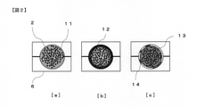
- FIG. 2 shows a cross-sectional view of the resin-impregnated fiber base material 7 of the drawing die 6 when cut in the normal direction with respect to the drawing direction.
- the resin-impregnated fiber base material 7 is introduced from the mold inlet of the pultrusion mold 6, and when it is conveyed in the pultrusion mold 6 heated to a constant temperature at a constant pultrusion speed, it is delivered from the pultrusion mold 6. Partial gelation begins with heating.
- FIG. 2A shows a gelled state of the thermosetting resin composition of the resin-impregnated fiber base material 7 at the initial stage of gelation.
- FIG. 2 [b] shows a stage in the latter half of gelation, and shows a state in which the thermosetting resin composition on the surface layer of the resin-impregnated fiber base material 7 is in a cured state.
- the resin-impregnated fiber base material 7 cannot hold the thermosetting resin composition, and a part of the resin component is likely to be left in the mold. ..
- the curable resin composition left behind is cured, and does not peel off from the inner surface of the pultrusion mold and remains adhered to it.
- FIG. 2 [c] when the matrix resin progresses to the inside of the resin-impregnated fiber base material 7 and the thermosetting resin composition is cured to the state 13 in which the curing shrinkage occurs, the curing is left behind.
- a so-called scale 14 resin residue is deposited, which causes scratch marks on the surface layer of the molded product and increases the pulling force during the manufacturing process, which causes thread breakage.
- a plurality of squeezers 5 are arranged between the resin impregnation tank and the mold inlet, and the squeezers 5a to 5d are respectively arranged.
- the number of squeezers 5 to be used is determined by the shape of the molded product and the number of filaments constituting the fiber bundle, but it is preferably 2 or more, and more preferably 3 or more.
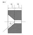
- FIG. 4 shows a side sectional view of any one of the squeezers 5 in which a plurality of squeezers 5 are arranged, when a surface cut in the tangential direction with respect to the drawing direction is used as a side sectional view.
- the squeezer 5 is composed of a fiber inlet portion 15 and a fiber squeezing portion 16, and the cross-sectional shape of the fiber squeezing portion 16 is similar to the die inlet cross-sectional shape of the mold, or from the contour line of the mold inlet cross-sectional shape of the mold. It is important to have a surface shape that is drawn at points separated by a certain distance.
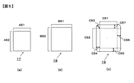
- FIG. 5 (b) shows an example of the cross-sectional shape 18 of the fiber drawing portion having a shape similar to the cross-sectional shape 17 of the mold inlet portion with respect to the cross-sectional shape 17 of the mold inlet portion shown in FIG. 5 (a).
- FIG. 5C shows an example of the cross-sectional shape 19 of the fiber drawing portion drawn at a point separated from the contour line of the cross-sectional shape 17 of the die inlet portion by a certain distance.
- FIG. 5 (c) A straight line portion separated from the contour line of 17 by a certain distance C54 to C57) The lengths of C51 and C52 are the same, and the adjacent straight line portions are connected by an arc having the same length C53 as C54 to C57. It is a thing.
- the shape obtained in FIG. 5 (c) is a shape drawn at a point separated from the contour line of the cross-sectional shape 17 of the mold inlet portion shown in FIG. 5 (a) by a certain distance.
- the squeezer 5 has a fiber inlet portion 15 having a tapered tapered surface and a fiber squeezing portion 16 connected to the fiber inlet portion 15.
- the inclination angle ⁇ is preferably 30 ° or more and 75 ° or less.
- the tapered tapered surface provided at the fiber inlet portion 15 does not cause excess resin to stay around the fiber drawing portion 16, and the excess resin is squeezed out without excess or deficiency. Can be done.
- the inlet cross-sectional shape of the fiber squeezing portion 16 and the outlet cross-sectional shape of the fiber squeezing portion 16 are the same, and the cross-sectional area S 1 (mm 2 ) on the fiber supply side of the fiber inlet portion 15 and the cross-sectional area S of the fiber squeezing portion 16 It is preferable that the ratio S 1 / S 2 to 2 (mm 2 ) is 1.2 times or more and 100 times or less. If the inlet cross-sectional shape of the fiber squeezing portion 16 and the outlet cross-sectional shape of the fiber squeezing portion 16 are the same, the excess resin can be squeezed with a small pulling force. When the above S 1 / S 2 is in the above preferable range, the excess resin contained in the resin-impregnated fiber bundle is easily discharged from the squeezer, while the squeezer size becomes appropriate, the production is easy, and the production cost can be suppressed.
- the thickness of the molded product is 0.1 times or more and 50 times or less. It is preferable to add a roundness (curved surface). By providing the roundness, the resin-impregnated fiber base material is aligned and the excess resin is discharged, so that unnecessary scratching is reduced when the fiber bundle is compressed, and it can be expected that fluffing is suppressed.
- a shape similar to the cross-sectional shape of the mold entrance is used as a contour line, and a surface shape drawn at least a part outside the contour line at a certain distance is combined. It is also preferable to use a squeezer having a cross-sectional shape of the fiber drawing portion.
- FIG. 6 shows an example of the cross-sectional shape of the squeezer.
- the cross-sectional shape 21 of the resin drawing portion of the squeezer shown in FIG. 6 (b) is the cross-sectional shape 20 of the mold inlet portion of FIG. 6 (a).
- a circular arc whose radius is a straight line portion B61 or B62 separated from the contour line by a certain distance B64 to B67 and an adjacent straight line portion B61 or B62 having the same length as B64 to B67. It is connected by.
- FIG. 6A is A61 / A62, and the contour line in FIG. 6B is separated from the contour line by a certain distance B64 to B67.
- the ratio of the lengths of the straight portions B61 / B62 is equal. With such a shape, excess resin is less likely to stay in the corners, and the continuous passage of the resin-impregnated fiber base material can be improved.
- the contour line is a shape similar to the cross-sectional shape 20 of the mold inlet portion of FIG. 6 (a).
- the remaining side of the contour line (lower side in FIG. 6C) is formed by extending the end portion and connecting it to a straight line portion separated from the contour line by a certain distance C64 to C66 to form a fiber drawing portion of the squeezer.
- the cross-sectional shape can be 22.
- the squeezers arranged at intervals are a squeezer having a fiber drawing portion similar to the mold entrance cross-sectional shape of the mold and a certain distance outward from the contour line of the mold entrance cross-sectional shape of the mold.
- a squeezer having the fiber squeezed portion having a surface shape drawn at points separated from each other, or a shape similar to the cross-sectional shape of the die entrance is used as the contour line, and the contour line is separated from at least a part of the contour line by a certain distance. It is also preferable to arrange a squeezer having a cross-sectional shape of the fiber drawing portion in which the surface shapes drawn by the dots are combined.
- the cross-sectional area of the cross-sectional shape of the fiber squeezing portion 16 in any squeezer is the cross-sectional area of the fiber squeezing portion 16 of the squeezer arranged on the downstream side of the arbitrary squeezer. It is preferable that the cross-sectional area is equal to or larger than the cross-sectional area of.
- the cross-sectional shape of the fiber squeezed portion 16 of the squeezers arranged in a plurality of sheets shall be 0.8 times or more and 3 times or less the cross-sectional area of the inlet cross-sectional shape of the die. If it is less than 0.8 times, the impregnation of the resin into the fiber bundle is insufficient, and if it is larger than 3 times, it becomes difficult to remove the excess resin invaded in the fiber bundle excessively.
- the arithmetic average roughness (Ra) of the surface of the fiber drawing portion 16 is preferably 0.05 or more and 2.00 or less.
- the arithmetic average roughness (Ra) referred to here indicates the arithmetic average roughness of the cross-sectional curve in JIS B 0601-2003, and is measured by the measuring method using the stylus type surface roughness measuring machine in JIS B 0633-2001. Will be done.
- the fiber volume fraction (Vf) of the reinforcing fiber bundle is preferably 50% or more and 80% or less.
- the thermosetting resin composition impregnated in the resin-impregnated fiber base material may be discharged more than necessary by the squeezer as a surplus resin.
- the amount of the thermosetting resin impregnated in the reinforcing fiber bundle 2 becomes appropriate, the reinforcing fiber bundle 2 is less likely to be directly scratched by the squeezer, and it is possible to effectively prevent an increase in pulling force and the occurrence of fluffing. ..
- thermosetting resin composition used in the present invention is preferably a resin composition containing at least the following components [A] to [D].
- the "epoxy resin” refers to a compound having two or more epoxy groups in one molecule.
- the resin composition used in the present invention contains at least one selected from inorganic carbon, silicon, magnesium, calcium and aluminum as the component [C], and uses a filler composed of a component having a Mohs hardness of 3 or less. Is preferable. In this case, since the filler penetrates between the carbon fibers of the resin-impregnated fiber base material 7, the effect of suppressing curing shrinkage can be obtained when the resin composition is cured. Further, when the Mohs hardness is 3 or less, it is soft, so that the influence on the mold is small and the damage to the mold can be reduced. Examples of the filler having a Mohs hardness of 3 or less include calcium carbonate, aluminum hydroxide, talc, carbon black and the like.
- a curing catalyst (component [E]) may be used for the epoxy resin composition.
- the component [E] is not particularly limited as long as it promotes the chemical reaction between the epoxy resin and the curing agent.
- glass fiber, aramid fiber, polyethylene fiber, silicon carbide fiber and carbon fiber are preferably used.
- the present invention can be applied to the molding of fiber-reinforced molded products having various shapes as long as the molded products have the same cross-sectional shape.
- a cylindrical rod-shaped molded product, a C-shaped cross section, a T-shaped cross section, and an I-shaped product examples thereof include various cross-sectional shape molded products having a cross section, an L-shaped cross section, a rod-shaped molded product having a polygonal cross section, a sheet-shaped thin molded product, a thick molded product having a rectangular cross section, and the like, and they are hollow. Is also good.
- the thickness of the molded product in the case of a hollow product, the thickness from the outermost surface to the hollow portion
- the thickness of the molded product is within 20 mm, and in particular, a columnar rod-shaped molding having a diameter of 1.0 to 10.0 mm. It is preferably a product, and the sudden curing shrinkage due to heat storage inside the molded product is suppressed and the dimensions are often stable, which is good from the viewpoint of dimensional stability.
- Ingredient [A] As an epoxy resin, bisphenol phenol F type epoxy "EPICLON” (registered trademark) 830 (manufactured by DIC Corporation)
- Ingredient [B] Methylnadic acid anhydride "Kayahard” (registered trademark) MCD (manufactured by Nippon Kayaku Co., Ltd.) as a curing agent
- Ingredient [C] As a filler, talc "micron white” (registered trademark) # 5000S (average particle size 4.75 ⁇ m, Mohs hardness 1, manufactured by Hayashi Kasei Co., Ltd.)
- Ingredient [D] Oleic acid ester "Chemlies” (registered trademark) IC-35 (manufactured by ChemTrend) as an internal mold release agent.
- T700SC-24K carbon fiber, manufactured by Toray Industries, Inc.
- the prepared resin composition is put into a resin impregnation tank 4 at 25 ° C., and the carbon fiber which is the reinforcing fiber bundle 2 is passed through the resin impregnation tank 4 containing the resin composition to impregnate the resin, and then the squeezer 5 is used.
- the reinforcing fiber bundle 2 was impregnated with the thermosetting resin composition and a part of the excess thermosetting resin composition was removed, and then the resin-impregnated fiber base material 7 was introduced into the mold inlet. At the time of this introduction, the thermosetting resin composition was in a liquid state.
- the resin-impregnated fiber base material 7 discharged from the mold outlet was introduced into an aftercure furnace 9 and further heat-cured in the furnace to form a pultruded product.
- Table 1 shows the molding conditions. Unless otherwise specified, a mold having a cavity having a perfect circular cross section with a diameter of 2.0 mm and having a hard chrome plating treatment on the surface was used. As the squeezer, a squeezer having a cavity having a perfect circular cross section having the diameter shown in Table 1 was used, and 1 to 4 sheets were arranged between the resin impregnation tank outlet and the mold inlet at intervals of 5 cm depending on the conditions. ..
- pultrusion was performed at a mold temperature Tp of 190 ° C., a mold passage length of 0.6 m, and a molding speed of 0.75 m / min.
- pultrusion was performed at a mold temperature Tp of 195 ° C., a mold passage length of 0.6 m, and a molding speed of 1.0 m / min.
- the molding distance of the molded product was measured using a total length meter. The measurement was started immediately after the molded product was derived from the mold, and the measured molding length was recorded when a defect in the product was confirmed or when a stop due to thread breakage occurred, and the maximum length was 5,000 m.
- Example 1 Using the above resin composition, molding was carried out using the apparatus shown in FIG. 1 using the molding conditions and squeezer conditions shown in Table 1. The molded product from the mold did not deform, and no thread breakage or stoppage was confirmed even at a molding distance of 5,000 m.
- Example 2 Using the above resin composition, molding was carried out using the apparatus shown in FIG. 1 using the molding conditions and squeezer conditions shown in Table 1. The molded product from the mold did not deform, and no thread breakage or stoppage was confirmed even at a molding distance of 5,000 m.
- Example 3 Using the above resin composition, molding was carried out using the apparatus shown in FIG. 1 using the molding conditions and squeezer conditions shown in Table 1. The molded product from the mold did not deform, and no thread breakage or stoppage was confirmed even at a molding distance of 5,000 m.
- Example 4 Using the above resin composition, molding was carried out using the apparatus shown in FIG. 1 using the molding conditions and squeezer conditions shown in Table 1. The molded product from the mold did not deform, and no thread breakage or stoppage was confirmed even at a molding distance of 5,000 m.
Landscapes
- Chemical & Material Sciences (AREA)
- Engineering & Computer Science (AREA)
- Composite Materials (AREA)
- Mechanical Engineering (AREA)
- Manufacturing & Machinery (AREA)
- Materials Engineering (AREA)
- Health & Medical Sciences (AREA)
- Chemical Kinetics & Catalysis (AREA)
- Medicinal Chemistry (AREA)
- Polymers & Plastics (AREA)
- Organic Chemistry (AREA)
- Moulding By Coating Moulds (AREA)
Priority Applications (3)
| Application Number | Priority Date | Filing Date | Title |
|---|---|---|---|
| US18/014,912 US20230249420A1 (en) | 2020-07-27 | 2021-07-19 | Method of producing fiber-reinforced molded article |
| CN202180039866.1A CN115698146B (zh) | 2020-07-27 | 2021-07-19 | 纤维增强成型品的制造方法 |
| JP2021542360A JPWO2022024834A1 (https=) | 2020-07-27 | 2021-07-19 |
Applications Claiming Priority (2)
| Application Number | Priority Date | Filing Date | Title |
|---|---|---|---|
| JP2020-126150 | 2020-07-27 | ||
| JP2020126150 | 2020-07-27 |
Publications (1)
| Publication Number | Publication Date |
|---|---|
| WO2022024834A1 true WO2022024834A1 (ja) | 2022-02-03 |
Family
ID=80036437
Family Applications (1)
| Application Number | Title | Priority Date | Filing Date |
|---|---|---|---|
| PCT/JP2021/026942 Ceased WO2022024834A1 (ja) | 2020-07-27 | 2021-07-19 | 繊維強化成形品の製造方法 |
Country Status (4)
| Country | Link |
|---|---|
| US (1) | US20230249420A1 (https=) |
| JP (1) | JPWO2022024834A1 (https=) |
| CN (1) | CN115698146B (https=) |
| WO (1) | WO2022024834A1 (https=) |
Families Citing this family (1)
| Publication number | Priority date | Publication date | Assignee | Title |
|---|---|---|---|---|
| CN116141708B (zh) * | 2023-03-21 | 2024-08-16 | 哈尔滨工业大学 | 混杂连续纤维增强热塑性复材筋的制造设备及制备方法 |
Citations (3)
| Publication number | Priority date | Publication date | Assignee | Title |
|---|---|---|---|---|
| JP2002160303A (ja) * | 2000-11-24 | 2002-06-04 | Mitsubishi Rayon Co Ltd | 一方向繊維強化プラスチックと、その引抜成形方法及び引抜成形用ダイス |
| JP2009173026A (ja) * | 2007-12-27 | 2009-08-06 | Toray Ind Inc | 棒状ハイブリッド部材の製造方法 |
| WO2019151174A1 (ja) * | 2018-01-31 | 2019-08-08 | 東レ株式会社 | 繊維強化成形品およびその製造方法 |
Family Cites Families (1)
| Publication number | Priority date | Publication date | Assignee | Title |
|---|---|---|---|---|
| EP2589475B1 (en) * | 2010-06-30 | 2020-06-17 | Toray Industries, Inc. | Process and apparatus for producing sheet-shaped prepreg |
-
2021
- 2021-07-19 WO PCT/JP2021/026942 patent/WO2022024834A1/ja not_active Ceased
- 2021-07-19 US US18/014,912 patent/US20230249420A1/en not_active Abandoned
- 2021-07-19 CN CN202180039866.1A patent/CN115698146B/zh active Active
- 2021-07-19 JP JP2021542360A patent/JPWO2022024834A1/ja active Pending
Patent Citations (3)
| Publication number | Priority date | Publication date | Assignee | Title |
|---|---|---|---|---|
| JP2002160303A (ja) * | 2000-11-24 | 2002-06-04 | Mitsubishi Rayon Co Ltd | 一方向繊維強化プラスチックと、その引抜成形方法及び引抜成形用ダイス |
| JP2009173026A (ja) * | 2007-12-27 | 2009-08-06 | Toray Ind Inc | 棒状ハイブリッド部材の製造方法 |
| WO2019151174A1 (ja) * | 2018-01-31 | 2019-08-08 | 東レ株式会社 | 繊維強化成形品およびその製造方法 |
Also Published As
| Publication number | Publication date |
|---|---|
| CN115698146A (zh) | 2023-02-03 |
| JPWO2022024834A1 (https=) | 2022-02-03 |
| CN115698146B (zh) | 2024-03-08 |
| US20230249420A1 (en) | 2023-08-10 |
Similar Documents
| Publication | Publication Date | Title |
|---|---|---|
| JP5572947B2 (ja) | 成形材料、および、繊維強化プラスチック、ならびに、これらの製造方法 | |
| JP7205464B2 (ja) | 繊維強化成形品およびその製造方法 | |
| US20200254654A1 (en) | Coated fiber-reinforced resin molded article and manufacturing method of the same | |
| JP5292972B2 (ja) | 繊維強化プラスチックの製造方法 | |
| WO1997031052A1 (en) | Epoxy resin composition for fiber-reinforced composite material, yarn prepreg, and process and apparatus for preparing the same | |
| US12570809B2 (en) | Unidirectional prepreg, fiber-reinforced thermoplastic resin sheet, manufacturing methods of unidirectional prepreg and fiber-reinforced thermoplastic resin sheet, and molded body | |
| JP2010023359A (ja) | 積層体の製造方法 | |
| JP6895682B2 (ja) | 一方向プリプレグ、繊維強化熱可塑性樹脂シート、一方向プリプレグおよび繊維強化熱可塑性樹脂シートの製造方法、ならびに、成形体 | |
| KR20190126810A (ko) | 프리프레그의 제조 방법 및 섬유 강화 복합 재료의 제조 방법 | |
| WO2022075265A1 (ja) | 繊維補強樹脂引抜成形体及びその製造方法 | |
| EP3275921A1 (en) | Impregnated prepreg comprising reinforcing fibers | |
| WO2022024834A1 (ja) | 繊維強化成形品の製造方法 | |
| CN108883587A (zh) | 碳纤维片状模塑料的制造方法和设备 | |
| CN116096543A (zh) | 片状模塑料和成形品的制造方法 | |
| JP2010253733A (ja) | 引抜成形品の製造方法 | |
| JP6094792B2 (ja) | プリプレグの製造方法 | |
| JP6836763B2 (ja) | 繊維強化熱可塑性樹脂シート、繊維強化熱可塑性樹脂シートの成形体、及び繊維強化熱可塑性樹脂シートの製造方法 | |
| JP7054499B2 (ja) | 繊維強化熱可塑性樹脂シートの製造方法 | |
| JP6798199B2 (ja) | 繊維強化プラスチック成形物 | |
| JPH10156982A (ja) | 繊維強化複合成形体およびその製造方法 | |
| JP2000254978A (ja) | Frp細線条体の製造方法 | |
| JP6900742B2 (ja) | トウプリプレグの製造方法および繊維強化複合材料の製造方法 | |
| JP7119539B2 (ja) | 炭素繊維強化樹脂成形品の製造方法 | |
| JP2004162055A (ja) | プリプレグの製造方法および製造装置 | |
| TW205053B (https=) |
Legal Events
| Date | Code | Title | Description |
|---|---|---|---|
| ENP | Entry into the national phase |
Ref document number: 2021542360 Country of ref document: JP Kind code of ref document: A |
|
| 121 | Ep: the epo has been informed by wipo that ep was designated in this application |
Ref document number: 21851375 Country of ref document: EP Kind code of ref document: A1 |
|
| NENP | Non-entry into the national phase |
Ref country code: DE |
|
| 122 | Ep: pct application non-entry in european phase |
Ref document number: 21851375 Country of ref document: EP Kind code of ref document: A1 |