WO2022024829A1 - 卓上照明装置 - Google Patents
卓上照明装置 Download PDFInfo
- Publication number
- WO2022024829A1 WO2022024829A1 PCT/JP2021/026903 JP2021026903W WO2022024829A1 WO 2022024829 A1 WO2022024829 A1 WO 2022024829A1 JP 2021026903 W JP2021026903 W JP 2021026903W WO 2022024829 A1 WO2022024829 A1 WO 2022024829A1
- Authority
- WO
- WIPO (PCT)
- Prior art keywords
- light
- main surface
- light guide
- guide plate
- lighting device
- Prior art date
- Legal status (The legal status is an assumption and is not a legal conclusion. Google has not performed a legal analysis and makes no representation as to the accuracy of the status listed.)
- Ceased
Links
Images









Classifications
-
- F—MECHANICAL ENGINEERING; LIGHTING; HEATING; WEAPONS; BLASTING
- F21—LIGHTING
- F21S—NON-PORTABLE LIGHTING DEVICES; SYSTEMS THEREOF; VEHICLE LIGHTING DEVICES SPECIALLY ADAPTED FOR VEHICLE EXTERIORS
- F21S6/00—Lighting devices intended to be free-standing
- F21S6/002—Table lamps, e.g. for ambient lighting
- F21S6/003—Table lamps, e.g. for ambient lighting for task lighting, e.g. for reading or desk work, e.g. angle poise lamps
-
- F—MECHANICAL ENGINEERING; LIGHTING; HEATING; WEAPONS; BLASTING
- F21—LIGHTING
- F21V—FUNCTIONAL FEATURES OR DETAILS OF LIGHTING DEVICES OR SYSTEMS THEREOF; STRUCTURAL COMBINATIONS OF LIGHTING DEVICES WITH OTHER ARTICLES, NOT OTHERWISE PROVIDED FOR
- F21V33/00—Structural combinations of lighting devices with other articles, not otherwise provided for
- F21V33/0004—Personal or domestic articles
- F21V33/0012—Furniture
-
- F—MECHANICAL ENGINEERING; LIGHTING; HEATING; WEAPONS; BLASTING
- F21—LIGHTING
- F21S—NON-PORTABLE LIGHTING DEVICES; SYSTEMS THEREOF; VEHICLE LIGHTING DEVICES SPECIALLY ADAPTED FOR VEHICLE EXTERIORS
- F21S6/00—Lighting devices intended to be free-standing
-
- G—PHYSICS
- G02—OPTICS
- G02B—OPTICAL ELEMENTS, SYSTEMS OR APPARATUS
- G02B6/00—Light guides; Structural details of arrangements comprising light guides and other optical elements, e.g. couplings
- G02B6/0001—Light guides; Structural details of arrangements comprising light guides and other optical elements, e.g. couplings specially adapted for lighting devices or systems
- G02B6/0011—Light guides; Structural details of arrangements comprising light guides and other optical elements, e.g. couplings specially adapted for lighting devices or systems the light guides being planar or of plate-like form
- G02B6/0081—Mechanical or electrical aspects of the light guide and light source in the lighting device peculiar to the adaptation to planar light guides, e.g. concerning packaging
- G02B6/0085—Means for removing heat created by the light source from the package
-
- G—PHYSICS
- G02—OPTICS
- G02B—OPTICAL ELEMENTS, SYSTEMS OR APPARATUS
- G02B6/00—Light guides; Structural details of arrangements comprising light guides and other optical elements, e.g. couplings
- G02B6/0001—Light guides; Structural details of arrangements comprising light guides and other optical elements, e.g. couplings specially adapted for lighting devices or systems
- G02B6/0011—Light guides; Structural details of arrangements comprising light guides and other optical elements, e.g. couplings specially adapted for lighting devices or systems the light guides being planar or of plate-like form
- G02B6/0081—Mechanical or electrical aspects of the light guide and light source in the lighting device peculiar to the adaptation to planar light guides, e.g. concerning packaging
- G02B6/0086—Positioning aspects
- G02B6/009—Positioning aspects of the light source in the package
-
- G—PHYSICS
- G02—OPTICS
- G02B—OPTICAL ELEMENTS, SYSTEMS OR APPARATUS
- G02B6/00—Light guides; Structural details of arrangements comprising light guides and other optical elements, e.g. couplings
- G02B6/0001—Light guides; Structural details of arrangements comprising light guides and other optical elements, e.g. couplings specially adapted for lighting devices or systems
- G02B6/0011—Light guides; Structural details of arrangements comprising light guides and other optical elements, e.g. couplings specially adapted for lighting devices or systems the light guides being planar or of plate-like form
- G02B6/0081—Mechanical or electrical aspects of the light guide and light source in the lighting device peculiar to the adaptation to planar light guides, e.g. concerning packaging
- G02B6/0086—Positioning aspects
- G02B6/0091—Positioning aspects of the light source relative to the light guide
-
- F—MECHANICAL ENGINEERING; LIGHTING; HEATING; WEAPONS; BLASTING
- F21—LIGHTING
- F21V—FUNCTIONAL FEATURES OR DETAILS OF LIGHTING DEVICES OR SYSTEMS THEREOF; STRUCTURAL COMBINATIONS OF LIGHTING DEVICES WITH OTHER ARTICLES, NOT OTHERWISE PROVIDED FOR
- F21V2200/00—Use of light guides, e.g. fibre optic devices, in lighting devices or systems
-
- F—MECHANICAL ENGINEERING; LIGHTING; HEATING; WEAPONS; BLASTING
- F21—LIGHTING
- F21Y—INDEXING SCHEME ASSOCIATED WITH SUBCLASSES F21K, F21L, F21S and F21V, RELATING TO THE FORM OR THE KIND OF THE LIGHT SOURCES OR OF THE COLOUR OF THE LIGHT EMITTED
- F21Y2103/00—Elongate light sources, e.g. fluorescent tubes
- F21Y2103/10—Elongate light sources, e.g. fluorescent tubes comprising a linear array of point-like light-generating elements
-
- F—MECHANICAL ENGINEERING; LIGHTING; HEATING; WEAPONS; BLASTING
- F21—LIGHTING
- F21Y—INDEXING SCHEME ASSOCIATED WITH SUBCLASSES F21K, F21L, F21S and F21V, RELATING TO THE FORM OR THE KIND OF THE LIGHT SOURCES OR OF THE COLOUR OF THE LIGHT EMITTED
- F21Y2115/00—Light-generating elements of semiconductor light sources
- F21Y2115/10—Light-emitting diodes [LED]
- F21Y2115/15—Organic light-emitting diodes [OLED]
-
- F—MECHANICAL ENGINEERING; LIGHTING; HEATING; WEAPONS; BLASTING
- F21—LIGHTING
- F21Y—INDEXING SCHEME ASSOCIATED WITH SUBCLASSES F21K, F21L, F21S and F21V, RELATING TO THE FORM OR THE KIND OF THE LIGHT SOURCES OR OF THE COLOUR OF THE LIGHT EMITTED
- F21Y2115/00—Light-generating elements of semiconductor light sources
- F21Y2115/20—Electroluminescent [EL] light sources
-
- G—PHYSICS
- G02—OPTICS
- G02B—OPTICAL ELEMENTS, SYSTEMS OR APPARATUS
- G02B6/00—Light guides; Structural details of arrangements comprising light guides and other optical elements, e.g. couplings
- G02B6/0001—Light guides; Structural details of arrangements comprising light guides and other optical elements, e.g. couplings specially adapted for lighting devices or systems
- G02B6/0011—Light guides; Structural details of arrangements comprising light guides and other optical elements, e.g. couplings specially adapted for lighting devices or systems the light guides being planar or of plate-like form
- G02B6/0033—Means for improving the coupling-out of light from the light guide
-
- G—PHYSICS
- G02—OPTICS
- G02B—OPTICAL ELEMENTS, SYSTEMS OR APPARATUS
- G02B6/00—Light guides; Structural details of arrangements comprising light guides and other optical elements, e.g. couplings
- G02B6/0001—Light guides; Structural details of arrangements comprising light guides and other optical elements, e.g. couplings specially adapted for lighting devices or systems
- G02B6/0011—Light guides; Structural details of arrangements comprising light guides and other optical elements, e.g. couplings specially adapted for lighting devices or systems the light guides being planar or of plate-like form
- G02B6/0033—Means for improving the coupling-out of light from the light guide
- G02B6/005—Means for improving the coupling-out of light from the light guide provided by one optical element, or plurality thereof, placed on the light output side of the light guide
Definitions
- the present invention relates to a desktop lighting device.
- LEDs light emitting diodes
- LED lighting since the luminous flux obtained from one LED is small, it is common to collect and use a plurality of LEDs. In such LED lighting, a phenomenon called “multiple shadows" in which shadows are generated by the number of light sources occurs, which causes flicker.
- a directional lighting device that changes light from an LED into planar or linear light emission with directivity has been proposed (see, for example, Patent Document 1).
- an LED light source is arranged with one side or two opposite sides of a light guide body made of a transparent member as an incident side.
- the lighting unit is located above the desk and the light emitting surface faces downward.
- the presence of the luminaire may cause the user to feel oppressive.
- the illumination light can be directly visually recognized, there is a risk that flicker may be felt and the concentration may be reduced.
- An object of the present invention is to provide a tabletop lighting device in which a feeling of oppression and flicker of light are reduced.
- a tabletop lighting device including a light source and a light guide plate including a light guide plate and a light guide portion for guiding light emitted from the light source.
- the light guide plate has a light incident surface for incident light from the light source, a first main surface for emitting light incident from the light incident surface, and a second main surface facing the first main surface.
- the first main surface is arranged substantially perpendicular to the installation surface of the tabletop lighting device.
- the axis passing through the center of the first main surface and perpendicular to the installation surface is defined as the vertical axis, and the direction parallel to the installation surface in the plane including the vertical axis and perpendicular to the installation surface.
- the angle at which the maximum strength is obtained is ⁇ 90 ° or more and less than 0 °.
- a light guide plate including a light guide plate and having transparency to visible light is used.
- the first main surface which is the light emitting surface of the light guide plate, is arranged perpendicular to the installation surface of the tabletop lighting device.
- the user can see through the back of the light guide unit, and the feeling of blockage and oppression is reduced.
- By giving a predetermined orientation to the distribution of the light emitted from the light emitting surface it is possible to prevent the irradiation light from being directly seen by the user and reduce flicker.
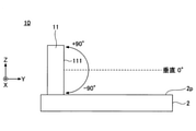
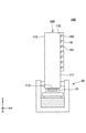
- FIG. 1 is an external view of the tabletop lighting device 10 of the embodiment.
- the tabletop lighting device 10 is placed on a desk, a table, or the like (hereinafter, collectively referred to as "desk 2").
- the surface on which the desktop lighting device 10 is placed is referred to as "installation surface 2p".
- the plane parallel to the installation surface 2p is the XY plane, and the direction orthogonal to the XY plane is the Z direction.
- the height direction of the tabletop lighting device 1 is the Z direction, and the width direction is the X direction.
- the light emission direction is the Y direction.
- the desktop lighting device 10 includes a light guide plate 11 and has a light guide unit 300 that guides light from a light source.
- the light source is omitted in FIG. 1, the light source may be housed inside a groove or slot formed in the installation surface 2p, or may be located on the installation surface 2p together with the light guide plate 11. A configuration example of the light source will be described later.
- the light guide plate 11 is a solid that is transparent to visible light, and is made of glass, plastic, or the like.
- glass material quartz glass, non-alkali glass, borosilicate glass and the like can be used.
- plastic material an acrylic resin (for example, polymethylmethacrylate (PMMA)), a polycarbonate (PC) resin, a cycloolefin (COP) resin, or the like can be used.
- PMMA polymethylmethacrylate
- PC polycarbonate
- COP cycloolefin
- the visible light transmittance of the light guide plate 11 is 60% or more, 65% or more, 70% or more, 75% or more, 80% or more, 85% or more, or 90% or more.
- the visible light transmittance is specified as an average value of the transmittance at each wavelength when measured at a measurement wavelength of 380 nm or more and 780 nm or less using a spectrophotometer.
- the light guide plate 11 has a first main surface 111 that emits light.
- the first main surface 111 is substantially perpendicular to the installation surface 2p.
- the term "almost vertical" means that an error of about ⁇ 5 ° with respect to the vertical may be included.
- the light emitted from the first main surface 111 has a light distribution distributed downward from the direction horizontal to the installation surface 2p. As long as this light cloth is satisfied, the first main surface 111 may include an error of about ⁇ 5 ° from the vertical.
- the axis that passes through the center C of the first main surface 111 and is perpendicular to the installation surface 2p is defined as the vertical axis or the V axis.
- the direction parallel to the installation surface 2p is defined as 0 ° perpendicular.
- An upward angle above 0 ° in the YY plane is defined as a positive angle, and a downward angle is defined as a negative angle.
- the angle at which the maximum intensity is in the light distribution of the emitted light from the center of the first main surface 111 is in the range of ⁇ 90 ° or more (for example, over ⁇ 90 °) and less than 0 °. Is set to.
- the upper limit is -0.1 °, -1 °, -5 °, -10 °, -10 °, -20 °, -30 °, -40 °, -50 °, -60 °, -70 °. , -80 °, -85 °, -88 °, -89 °
- the lower limit is -90 °, -89 °, -88 °, -85 °, -80 °, -70 °, -60. °, -50 °, -40 °, -30 °, -20 °, -10 °, -5 °, -1 °, and the lower limit value does not exceed the upper limit value.
- the light distribution of the emitted light can be measured using a viewing angle measuring device (for example, the luminance viewing angle measuring device EZContrast XL88 manufactured by ELDIM).
- the axis passing through the center C and horizontal to the installation surface 2p is defined as the horizontal axis or the H axis.
- the angle from the center C of the first main surface 111 toward the Y direction is horizontal 0 °.
- the clockwise angle is a positive angle
- the counterclockwise angle is a counterclockwise angle from 0 ° horizontally. The angle should be negative.
- the horizontal distribution of light emitted from the first principal plane 111 is in the range of ⁇ 90 ° to + 90 °, for example, above ⁇ 90 ° and within + 90 °.
- the lower limit is -90 °, -89 °, -88 °, -85 °, -80 °, -70 °, -60 °, -50 °, -40 °, -30 °, -20 °,- It is 10 °, and its upper limit is + 90 °, + 89 °, + 88 °, + 85 °, + 80 °, + 70 °, + 60 °, + 50 °, + 40 °, + 30 °, + 20 °, + 10 °.
- the tabletop lighting device 10 may have a substantially uniform light distribution in the horizontal direction.
- FIG. 2 is a diagram defining the vertical angle of the tabletop lighting device 10
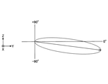
- FIG. 3 is a diagram showing the light distribution characteristics in the YY plane.
- the coordinate systems of FIGS. 2 and 3 are the same as those of FIG. In FIG. 2, the YZ plane perpendicular to the installation plane 2p, and generally the angle range that can be taken in the vertical direction is ⁇ 90 ° to + 90 °.
- the first main surface 111 of the tabletop lighting device 10 of the embodiment is configured such that the angle at which the maximum intensity is obtained in the light distribution of the emitted light is in the range of ⁇ 90 ° or more and less than 0 °. ing.
- the work of the installation surface 2p By setting the angle that becomes the maximum intensity in the light distribution of the emitted light from the center of the emitting surface (that is, the angle formed by the arrow in FIG. 3) in the range of ⁇ 90 ° or more and less than 0 °, the work of the installation surface 2p It illuminates the area with sufficient illumination and prevents the emitted light from directly entering the user's eyes. This prevents the user from feeling flicker and suppresses a decrease in work efficiency.
- FIG. 4 is a diagram defining the horizontal angle of the tabletop lighting device 10
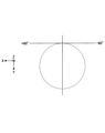
- FIG. 5 is a diagram showing the light distribution characteristics in the XY plane.
- the coordinate systems of FIGS. 4 and 5 are the same as those of FIG. In FIG. 4, in the XY plane horizontal to the installation surface 2p, the angle range that can be taken in the horizontal direction is ⁇ 90 ° to + 90 °.
- the first main surface 111 of the tabletop lighting device 10 has a light distribution of emitted light within a range of ⁇ 90 ° to + 90 ° in the horizontal direction.
- the work area of the installation surface 2p can be illuminated almost uniformly, and the work efficiency of the user can be improved.
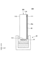
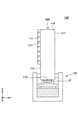
- FIG. 6 is a diagram showing a configuration example of the light source unit 30 of the desktop lighting device 10.
- the tabletop lighting device 10 includes a light source unit 30 and a light guide unit 300 that includes a light guide plate 11 and guides light emitted from the light source unit 30.
- the light guide plate 11 has a light incident surface 113 that incidents light from the light source unit 30, a first main surface 111 that emits light incident from the light incident surface 113 to the outside, and a second surface facing the first main surface 111. It has a main surface 112.
- the first main surface 111 is configured to emit light in a range of ⁇ 90 ° or more and less than 0 ° in the vertical direction. It is more preferable that the first main surface 111 has a configuration in which light is emitted in the range of ⁇ 90 ° to + 90 ° in the horizontal direction.
- the light incident surface 113 is located at the lower end of the light guide plate 11 in the Z direction, and the light source unit 30 is arranged below the light guide plate 11.
- the arrangement of the light source unit 30 is not limited to this example, and may be provided at the side end portion of the light guide plate 11.
- the light source unit 30 has, for example, a light emitting element 31 housed in the housing 35 as a light source.
- the light emitting element 31 may be mounted on the substrate 32 and fixed to the heat radiating portion 33 with the heat conductive double-sided tape 34.
- an organic electroluminescence (EL) light emitter or an inorganic EL light emitter capable of surface emission, or a linear light source such as a fluorescent lamp or a cold cathode fluorescent lamp may be used.
- the light guide plate 11 is held in the housing 35 by the holding member 36 so that the first main surface 111 is substantially perpendicular to the installation surface of the tabletop lighting device 10.
- the light source unit 30 may be housed inside a groove or a slot formed in the desk 2 together with the housing 35, or may be placed on the surface of the desk 2 together with the housing 35.
- the light guide unit 300 has a low refractive index layer having a refractive index lower than that of the light guide plate 11 on at least one of the first main surface 111 and the second main surface 112 of the light guide plate 11.
- the low refractive index layer is a layer having a low refractive index with respect to the refractive index of the light guide plate 11.
- the refractive index n 1 of the light guide plate 11 is around 1.49.
- the refractive index n 2 of the low refractive index layer is preferably 1.30 or less, and more preferably 1.20 or less.
- the low refractive index layer is not particularly limited, but for example, a low refractive index layer having voids disclosed in International Publication No. 2019/146628 can be used. This content is incorporated herein by reference.
- the visible light transmittance of the light guide plate 11 and the light guide unit 300 having a low refractive index layer is 60% or more, 65% or more, 70% or more, 75% or more, 80% or more, 85% or more, or 90% or more. ..
- the visible light transmittance is specified as an average value of the transmittance at each wavelength when measured at a measurement wavelength of 380 nm or more and 780 nm or less using a spectrophotometer.
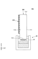
- the desktop lighting device 10A has a light source unit 30 and a light guide unit 300 including a light guide plate 11A.
- the light source unit 30 has a light emitting element 31 that emits light to the light guide plate 11A.
- Other configurations of the light source unit 30 are arbitrary, and for example, the configuration of FIG. 6 can be adopted.
- the light guide plate 11A has a light incident surface 113 facing the light emitting element 31, a first main surface 111, and a second main surface 112, and the low refractive index layer 26 is provided on the first main surface 111.
- the low refractive index layer 26 may be covered with the cover layer 28a.
- the light incident on the light guide plate 11A from the light incident surface 113 propagates in the light guide plate 11A in the Z direction while being totally reflected between the first main surface 111 provided with the low refractive index layer 26 and the second main surface 112. do.
- the light that does not satisfy the total reflection conditions has an angle that becomes the maximum intensity in the light distribution of the emitted light from the center of the first main surface 111. It is emitted from the first main surface 111 so as to be in the range of ⁇ 90 ° or more and less than 0 ° on the YY surface. In the horizontal direction (XY plane), the light distribution of the emitted light may have a distribution in the range of ⁇ 90 ° to + 90 °.
- the low refractive index layer 26 By providing the low refractive index layer 26 on the first main surface 111, it is possible to suppress light loss due to dirt and scratches on the light emitting surface.
- the desktop lighting device 10B has a light source unit 30 and a light guide unit 300 including a light guide plate 11B.
- the light source unit 30 has a light emitting element 31 that emits light to the light guide plate 11B.
- Other configurations of the light source unit 30 are arbitrary, and for example, the configuration of FIG. 6 can be adopted.
- the light guide plate 11B has a light incident surface 113 facing the light emitting element 31, a first main surface 111, and a second main surface 112, and the low refractive index layer 27 is provided on the second main surface 112.
- the low refractive index layer 26 may be covered with the cover layer 28b.
- the light incident on the light guide plate 11B from the light incident surface 113 is totally reflected between the first main surface 111 and the interface of the second main surface 112 provided with the low refractive index layer 27, and Z the light guide plate 11B. Propagate in the direction.
- the light that does not satisfy the total reflection condition has an angle of -90 at which the maximum intensity in the light distribution of the emitted light from the center of the first main surface 111 is -90. It is emitted from the first main surface 111 so as to be in the range of ° or more and less than 0 °.
- the light distribution of the emitted light may have a distribution in the range of ⁇ 90 ° to + 90 °.
- the desktop lighting device 10C has a light source unit 30 and a light guide unit 300 including a light guide plate 11C.
- the light source unit 30 has a light emitting element 31 that outputs light incident on the light guide plate 11C.
- Other configurations of the light source unit 30 are arbitrary, and for example, the same configuration as in FIG. 6 can be adopted.
- the light guide plate 11C has a light incident surface 113 facing the light emitting element 31, a first main surface 111, and a second main surface 112.
- the low refractive index layer 26 is provided on the first main surface 111, and the low refractive index layer 27 is provided on the second main surface 112.
- the low refractive index layers 26 and 27 may be covered with the cover layers 28a and 28b, respectively.
- the light incident on the light guide plate 11C from the light incident surface 113 is totally reflected between the first main surface 111 provided with the low refractive index layer 26 and the second main surface 112 provided with the low refractive index layer 27. While propagating in the Z direction, the light guide plate 11C is propagated.
- the light that does not satisfy the total reflection conditions has an angle that becomes the maximum intensity in the light distribution of the emitted light from the center of the first main surface 111. It is emitted so as to be in the range of ⁇ 90 ° or more and less than 0 ° on the YZ plane. In the horizontal direction (XY plane), the light distribution of the emitted light may have a distribution in the range of ⁇ 90 ° to + 90 °.
- FIG. 8 is a diagram illustrating the significance of providing the low refractive index layers 26 and 27.
- the low refractive index layer 26 or 27 on at least one of the first main surface 111 and the second main surface 112, it is possible to prevent the light propagating inside the light guide plate 11 from being lost due to scattering or the like. As a result, the emission efficiency from the first main surface 111 can be maintained high.
- FIG. 9 is a schematic view of the tabletop lighting device 10D.
- the tabletop lighting device 10D has a light source unit 30 and a light guide unit 300 including a light guide plate 11D.
- the light source unit 30 has a configuration described with reference to FIG. 6, for example.
- the light guide plate 11D has one or more light cavities 151 inside, and a light extraction portion 15 is formed on the first main surface 111.
- the optical cavity 151 is a void filled with a material having a refractive index lower than that of the light guide plate 11. If the inside of the void is air, it becomes an air cavity. In addition to air, a gas, liquid, or solid material having a refractive index lower than that of the light guide plate 11 may be filled.
- the optical cavity 151 the light incident on the interface of the optical cavity 151 from the light guide plate 11D is totally reflected in the direction of the first main surface 111, and the maximum intensity in the light distribution of the emitted light from the center of the first main surface 111 is reached.
- the angle is designed to be in the range of ⁇ 90 ° or more and less than 0 ° on the YZ plane.
- the visible light transmittance of the light guide unit 300 having the light guide plate 11D and the light extraction unit 15 is 60% or more, 65% or more, 70% or more, 75% or more, 80% or more, 85% or more, or 90% or more. ..
- the visible light transmittance is specified as an average value of the transmittance at each wavelength when measured at a measurement wavelength of 380 nm or more and 780 nm or less using a spectrophotometer.
- the light guide plate 11D is provided with a plurality of optical cavities 151 regularly or randomly along the plane of the first main surface 111.
- the size of the optical cavity 151 can be appropriately selected within a range that can be installed inside the light guide plate 11E.
- the light guide plate containing the optical cavity is not particularly limited, and is, for example, International Publication No. 2011/124765, International Publication No. 2011/127187, International Publication No. 2019/087118, International Publication No. 2019/182091.
- the disclosed light guide plate can be used. These contents are incorporated herein by reference.
- the light guide plate 11D including the optical cavity 151 inside is manufactured, for example, by laminating a light guide layer having a desired cavity pattern formed on its surface and a flat light guide layer having no cavity pattern.
- the light guide layers are bonded to each other by lamination such as an adhesive-free microwave surface treatment, crimping with an adhesive (including a pressure-sensitive adhesive), or the like.
- an adhesive including a pressure-sensitive adhesive
- an adhesive it is preferable to use an adhesive having a refractive index substantially equal to that of the light guide layer.
- the formation of the cavity pattern on the light guide layer is carried out by laser patterning, direct laser imaging, laser drill, maskless laser irradiation, electron beam irradiation, or the like.
- individual characteristics may be imparted to the portion to be the optical cavity 151 by printing, inkjet printing, screen printing, or the like.
- Micro / nano-dispensing, dosing, direct writing, discrete laser sintering, micro-electric discharge machining (EDM), micromachining, micromolding, imprinting, embossing and the like may be used.
- the light guide plate 11D allows the light incident from the light incident surface 113 to be emitted from the first main surface 111 with the above-mentioned light distribution distribution while being propagated in the Z direction by total reflection.
- FIG. 10 is a schematic diagram of the desktop lighting device 10E.
- the tabletop lighting device 10E has a light source unit 30 and a light guide unit 300 including a light guide plate 11E.
- the light guide plate 11E is provided with a light extraction layer 16 that functions as a light extraction unit on the first main surface 111.
- One or more light cavities 161 are formed in the light extraction layer 16.
- the light extraction layer 16 having the optical cavity 161 may be formed by laminating a flat light guide layer having no cavity pattern and a light guide layer having a cavity pattern formed on the surface thereof, similarly to the light guide plate 11D of FIG. ..
- the light guide layer on which the cavity pattern is formed may be directly attached to the first main surface 111.
- the refractive index of the light extraction layer 16 and the refractive index of the light guide plate 11E are the same or close to each other.
- the light guide plate 11E is made of polymethylmethacrylate (PMMA)
- the light extraction layer 16 is made of a material having the same or similar refractive index as PMMA.
- the light incident on the light extraction layer 16 from the light guide plate 11E is totally reflected at the interface of the optical cavity 161 and emitted from the outermost surface 162 of the light extraction layer 16.
- the light incident from the light guide plate 11E is totally reflected in the direction of the outermost surface 162 of the light extraction layer 16, and the maximum intensity in the light distribution of the emitted light from the center of the first main surface 111 is reached.
- the angle is designed to be emitted in an angle range of ⁇ 90 ° or more and less than 0 ° in the YZ plane.
- the light guide plate 11E allows the light incident from the light incident surface 113 to be emitted from the light extraction layer 16 with the above-mentioned light distribution distribution while being propagated in the Z direction by total reflection.
- FIG. 11 is a schematic diagram of the desktop lighting device 10F.
- the tabletop lighting device 10F has a light source unit 30 and a light guide unit 300 including a light guide plate 11F.
- the light guide plate 11F is provided with a light extraction layer 17 that functions as a light extraction unit on the second main surface 112.
- One or more light cavities 171 are formed in the light extraction layer 17.
- the light extraction layer 17 having the optical cavity 171 has a flat light guide layer without a cavity pattern and a guide having a cavity pattern formed on the surface thereof, similarly to the light guide plate 11D in FIG. 9 and the light extraction layer 16 in FIG. It can be formed by laminating with a light layer. Alternatively, the light guide layer on which the cavity pattern is formed may be directly attached to the second main surface 112.
- the refractive index of the light extraction layer 17 and the refractive index of the light guide plate 11F are the same or close to each other.
- the light guide plate 11F is made of polymethylmethacrylate (PMMA)
- the light extraction layer 17 is made of a material having the same or similar refractive index as PMMA.
- the angle at which the maximum intensity is in the light distribution of the emitted light from the center of the first main surface 111 is ⁇ 90 ° or more and less than 0 ° in the YY plane.
- the light guide plate 11F guides the light incident from the light incident surface 113 in the direction of the first main surface 111 from the light extraction layer 17 while propagating the light incident from the light incident surface 113 in the Z direction by total reflection, and described above from the first main surface 111. It can emit light with a predetermined light distribution.
- FIG. 12 is a schematic diagram of the desktop lighting device 10G.
- the tabletop lighting device 10G has a light guide unit 300 including a light guide plate 11G.
- the light guide plate 11G is provided with a prism portion 251 as a light extraction portion on the first main surface 111.
- a prism sheet may be attached to the first main surface 111. In this case, it is desirable that the prism sheet and the light guide plate 11G have the same or close refractive indexes.
- the size of the prism portion 251 and the number of slopes are appropriately selected within the range in which the prism portion 251 can be arranged on the first main surface 111.
- the light incident on the prism portion 251 from the light guide plate 11G is refracted by the prism portion 251 and emitted from the light guide plate 11G.
- the angle and pitch of the inclined surface of the prism portion 251 are such that the angle at which the maximum intensity in the light distribution of the emitted light from the center of the first main surface 111 is ⁇ 90 ° or more in the YZ plane is 0 or more. Designed to be less than °.
- FIG. 13 is a schematic diagram of the desktop lighting device 10H.
- the tabletop lighting device 10H has a light guide unit 300 including a light guide plate 11H.
- the light guide plate 11H is provided with a prism portion 252 as a light extraction portion on the second main surface 112.
- a prism sheet may be attached to the second main surface 112. In this case, it is desirable that the prism sheet and the light guide plate 11H have the same or close refractive indexes.
- the size of the prism portion 252, the number of slopes, and the like are appropriately selected within the range in which the prism portion 252 can be arranged on the second main surface 112.
- the light incident on the prism portion 252 from the light guide plate 11H is refracted in the direction of the first main surface 111 by the prism portion 252 and emitted from the first main surface 111.
- the angle and pitch of the inclined surface of the prism portion 252 are such that the angle at which the maximum intensity in the light distribution of the emitted light from the center of the first main surface 111 is ⁇ 90 ° or more in the YZ plane is 0 or more. Designed to be less than °.
- FIG. 12 or FIG. 13 also illuminates the work area with sufficient illuminance, prevents the emitted light rays from directly entering the user's eyes, and suppresses flicker.
- FIG. 14 is a schematic diagram of the tabletop lighting device 10I.
- the tabletop lighting device 10I has a light guide unit 300 including a light guide plate 11I.
- the light guide plate 11I is provided with an uneven portion 253 as a light extraction portion on the first main surface 111.
- the uneven portion 253 has a plurality of convex portions or concave portions having a width (or diameter) of about 1 to 5 ⁇ m and a height.
- the uneven portion 253 is designed so that the angle at which the maximum intensity is obtained in the light distribution of the emitted light from the center of the first main surface 111 is ⁇ 90 ° or more and less than 0 ° in the YZ plane.
- an optical film having concave portions and convex portions that satisfy the above conditions may be used.
- FIG. 15 is a schematic diagram of the tabletop lighting device 10J.
- the tabletop lighting device 10J has a light guide unit 300 including a light guide plate 11J.
- the light guide plate 11J is provided with an uneven portion 254 as a light extraction portion on the second main surface 112.
- the uneven portion 254 has a plurality of convex portions or concave portions having a width (or diameter) of about 1 to 5 ⁇ m and a height.
- the uneven portion 254 deflects the light incident on the uneven portion 254 from the light guide plate 11J toward the first main surface 111 and emits the light from the first main surface 111.
- the uneven portion 254 is designed so that the angle at which the maximum intensity is in the light distribution of the emitted light from the center of the first main surface 111 is ⁇ 90 ° or more and less than 0 ° in the YZ plane.
- an optical film having concave portions and convex portions that satisfy the above conditions may be used.
- FIG. 14 or FIG. 15 also illuminates the work area with sufficient illuminance, prevents the emitted light rays from directly entering the user's eyes, and suppresses flicker.
- 16 and 17 are views showing a usage mode of the tabletop lighting device 10.
- the light incident surface 113 of the light guide plate 11 is arranged parallel to the installation surface 2p of the tabletop lighting device 10, and the light source unit 30 is arranged so as to face the light incident surface 113.
- the light source unit 30 is arranged so as to face the light incident surface 113.
- a plurality of light emitting elements 31 are arranged in the X direction. The light output from each light emitting element 31 is incident on the light incident surface 113 at the lower end of the light guide plate 11, and while propagating in the Z direction through the light guide plate 11, the first main surface 111 has a light distribution distributed as shown in FIG. Is output from.
- the light incident surface 113 of the light guide plate 11 is arranged perpendicular to the installation surface 2p of the tabletop lighting device 10, and the light source unit 30 is located along the light incident surface 113 of the light guide plate 11 from the installation surface 2p. It is extended in the Z direction.
- the light source unit 30 a plurality of light emitting elements 31 are arranged in the Z direction.
- the side end surface of the light guide plate 11 facing the light emitting element 31 of the light source unit 30 is the light incident surface 113.
- each light emitting element 31 is incident on the light incident surface 113 at the side end of the light guide plate 11, and while propagating in the X direction through the light guide plate 11, the first main light distribution is shown in FIG. It is output from the surface 111.
- the light guide plate 11 Since the light guide plate 11 is transparent to visible light, the user can see behind the light guide plate 11 in both the usage mode of FIG. 16 and the usage mode of FIG. 17, and an open lighting space is provided.
- FIG. 18 is a schematic diagram illustrating the effect of the desktop lighting device 10.
- the illumination light is emitted in a range of ⁇ 90 ° or more and less than 0 ° in the vertical direction.
- the emitted light illuminates the user's work surface and hand with uniform brightness. The user can visually recognize the work surface and also see behind the tabletop lighting device 10 through the tabletop lighting device 10.
- the light emitted from the tabletop lighting device 10 is rarely visually recognized. Therefore, the feeling of flicker is reduced and the work efficiency is maintained.
- the present invention has been described above based on a specific configuration example, the present invention is not limited to the above-mentioned configuration example.
- the configuration in which the low refractive index layer of FIGS. 7A to 7C is provided and the light extraction configuration of FIGS. 9 to 15 may be arbitrarily combined.
- the arrangement direction of the light emitting elements 31 of the light source unit 30 may be horizontal or vertical. In either case, the transparent light guide plate emits light in a direction that is difficult for the user to directly see, thereby realizing an open lighting space with reduced oppressive feeling and light flicker.
Landscapes
- Physics & Mathematics (AREA)
- Engineering & Computer Science (AREA)
- General Engineering & Computer Science (AREA)
- General Physics & Mathematics (AREA)
- Optics & Photonics (AREA)
- Health & Medical Sciences (AREA)
- Public Health (AREA)
- Planar Illumination Modules (AREA)
Priority Applications (5)
| Application Number | Priority Date | Filing Date | Title |
|---|---|---|---|
| KR1020237001987A KR20230044187A (ko) | 2020-07-28 | 2021-07-19 | 탁상 조명 장치 |
| US18/017,503 US11940120B2 (en) | 2020-07-28 | 2021-07-19 | Desktop illumination device |
| CN202180059492.XA CN116157618B (zh) | 2020-07-28 | 2021-07-19 | 桌面照明装置 |
| JP2022540196A JP7625606B2 (ja) | 2020-07-28 | 2021-07-19 | 卓上照明装置 |
| EP21849448.2A EP4191125A4 (en) | 2020-07-28 | 2021-07-19 | TABLE TOP LIGHTING DEVICE |
Applications Claiming Priority (2)
| Application Number | Priority Date | Filing Date | Title |
|---|---|---|---|
| JP2020127348 | 2020-07-28 | ||
| JP2020-127348 | 2020-07-28 |
Publications (1)
| Publication Number | Publication Date |
|---|---|
| WO2022024829A1 true WO2022024829A1 (ja) | 2022-02-03 |
Family
ID=80036426
Family Applications (1)
| Application Number | Title | Priority Date | Filing Date |
|---|---|---|---|
| PCT/JP2021/026903 Ceased WO2022024829A1 (ja) | 2020-07-28 | 2021-07-19 | 卓上照明装置 |
Country Status (7)
| Country | Link |
|---|---|
| US (1) | US11940120B2 (https=) |
| EP (1) | EP4191125A4 (https=) |
| JP (1) | JP7625606B2 (https=) |
| KR (1) | KR20230044187A (https=) |
| CN (1) | CN116157618B (https=) |
| TW (1) | TWI887456B (https=) |
| WO (1) | WO2022024829A1 (https=) |
Families Citing this family (1)
| Publication number | Priority date | Publication date | Assignee | Title |
|---|---|---|---|---|
| US20230296217A1 (en) * | 2020-07-28 | 2023-09-21 | Nitto Denko Corporation | Surface illumination device, space including surface illumination device, and illumination method |
Citations (14)
| Publication number | Priority date | Publication date | Assignee | Title |
|---|---|---|---|---|
| JPH08248421A (ja) * | 1995-03-07 | 1996-09-27 | Sony Corp | 導光部材 |
| JP2003202568A (ja) * | 2001-10-24 | 2003-07-18 | Sharp Corp | 導光体およびその製造方法、面状光源装置、表示装置 |
| JP2009110783A (ja) | 2007-10-30 | 2009-05-21 | Colcoat Kk | 指向性照明装置 |
| JP2011028868A (ja) * | 2009-07-21 | 2011-02-10 | Inax Corp | キッチンの照明装置 |
| WO2011124765A1 (en) | 2010-04-06 | 2011-10-13 | Kari Rinko | Laminate structure with embedded cavities and related method of manufacture |
| WO2011127187A1 (en) | 2010-04-06 | 2011-10-13 | Modilis Holding Llc | Internal cavity optics |
| JP2012156082A (ja) * | 2011-01-28 | 2012-08-16 | Furukawa Electric Co Ltd:The | バックライトパネル、導光板、反射板、および接着シート |
| US20120268966A1 (en) * | 2011-04-20 | 2012-10-25 | Rambus Inc. | Lighting assembly |
| JP2013200993A (ja) * | 2012-03-23 | 2013-10-03 | Konica Minolta Inc | 導光板、照明装置及び照明スタンド |
| JP2018500719A (ja) * | 2014-10-21 | 2018-01-11 | サン−ゴバン アドフォル | 統合型照明を有するパネル |
| WO2019087118A1 (en) | 2017-11-01 | 2019-05-09 | Nitto Denko Corporation | Light distribution structure and element, related method and uses |
| WO2019146628A1 (ja) | 2018-01-26 | 2019-08-01 | 日東電工株式会社 | Led照明器具用フィルム、led照明器具 |
| WO2019182098A1 (ja) * | 2018-03-22 | 2019-09-26 | 日東電工株式会社 | 光学デバイス |
| JP2020127348A (ja) | 2019-02-06 | 2020-08-20 | Njコンポーネント株式会社 | ステーター、モーター、およびステーターの製造方法 |
Family Cites Families (15)
| Publication number | Priority date | Publication date | Assignee | Title |
|---|---|---|---|---|
| JP4960327B2 (ja) * | 2002-08-02 | 2012-06-27 | 三菱レイヨン株式会社 | 光偏向素子及び光源装置 |
| JP4239700B2 (ja) * | 2003-06-17 | 2009-03-18 | オムロン株式会社 | 面光源装置及び当該面光源装置を用いた機器 |
| JP4547276B2 (ja) * | 2005-01-24 | 2010-09-22 | シチズン電子株式会社 | 面状光源 |
| TWM272939U (en) * | 2005-04-12 | 2005-08-11 | Keeper Technology Co Ltd | Illuminator with light-guiding structure |
| KR100638874B1 (ko) * | 2005-07-06 | 2006-10-27 | 삼성전기주식회사 | Led 광원이 도광판에 삽입된 백라이트 장치의광원-도광판 구조 및 이를 포함하는 백라이트 장치 |
| JP2009265960A (ja) * | 2008-04-25 | 2009-11-12 | Panasonic Corp | 信号機 |
| CN101598285A (zh) * | 2009-03-02 | 2009-12-09 | 广东明家科技股份有限公司 | 二极管折射式天顶灯 |
| CN201420958Y (zh) * | 2009-04-07 | 2010-03-10 | 辅祥实业股份有限公司 | 夜间阅读照明光板 |
| CN201425205Y (zh) * | 2009-05-21 | 2010-03-17 | 潘文莘 | 能够产生均匀条状光源的发光二极管照明装置及照明模块 |
| TWI416049B (zh) * | 2010-09-10 | 2013-11-21 | Young Lighting Technology Corp | 光源裝置及光源裝置的使用方法 |
| CN102997106A (zh) * | 2011-09-09 | 2013-03-27 | 柯尼卡美能达先进多层薄膜株式会社 | 照明装置以及照明台灯 |
| JP2015146294A (ja) * | 2014-02-04 | 2015-08-13 | ソニー株式会社 | 照明装置および表示装置 |
| EP3735552B1 (en) * | 2018-01-02 | 2021-11-10 | Signify Holding B.V. | Table lamp |
| KR102746689B1 (ko) * | 2018-05-21 | 2024-12-26 | 닛토덴코 가부시키가이샤 | 개량된 배광 소자 |
| CH715534A1 (de) * | 2018-11-12 | 2020-05-15 | Regent Beleuchtungskoerper Ag | Optik und Tischleuchte. |
-
2021
- 2021-07-19 EP EP21849448.2A patent/EP4191125A4/en active Pending
- 2021-07-19 WO PCT/JP2021/026903 patent/WO2022024829A1/ja not_active Ceased
- 2021-07-19 KR KR1020237001987A patent/KR20230044187A/ko active Pending
- 2021-07-19 US US18/017,503 patent/US11940120B2/en active Active
- 2021-07-19 JP JP2022540196A patent/JP7625606B2/ja active Active
- 2021-07-19 CN CN202180059492.XA patent/CN116157618B/zh active Active
- 2021-07-23 TW TW110127133A patent/TWI887456B/zh active
Patent Citations (15)
| Publication number | Priority date | Publication date | Assignee | Title |
|---|---|---|---|---|
| JPH08248421A (ja) * | 1995-03-07 | 1996-09-27 | Sony Corp | 導光部材 |
| JP2003202568A (ja) * | 2001-10-24 | 2003-07-18 | Sharp Corp | 導光体およびその製造方法、面状光源装置、表示装置 |
| JP2009110783A (ja) | 2007-10-30 | 2009-05-21 | Colcoat Kk | 指向性照明装置 |
| JP2011028868A (ja) * | 2009-07-21 | 2011-02-10 | Inax Corp | キッチンの照明装置 |
| WO2011124765A1 (en) | 2010-04-06 | 2011-10-13 | Kari Rinko | Laminate structure with embedded cavities and related method of manufacture |
| WO2011127187A1 (en) | 2010-04-06 | 2011-10-13 | Modilis Holding Llc | Internal cavity optics |
| JP2012156082A (ja) * | 2011-01-28 | 2012-08-16 | Furukawa Electric Co Ltd:The | バックライトパネル、導光板、反射板、および接着シート |
| US20120268966A1 (en) * | 2011-04-20 | 2012-10-25 | Rambus Inc. | Lighting assembly |
| JP2013200993A (ja) * | 2012-03-23 | 2013-10-03 | Konica Minolta Inc | 導光板、照明装置及び照明スタンド |
| JP2018500719A (ja) * | 2014-10-21 | 2018-01-11 | サン−ゴバン アドフォル | 統合型照明を有するパネル |
| WO2019087118A1 (en) | 2017-11-01 | 2019-05-09 | Nitto Denko Corporation | Light distribution structure and element, related method and uses |
| WO2019146628A1 (ja) | 2018-01-26 | 2019-08-01 | 日東電工株式会社 | Led照明器具用フィルム、led照明器具 |
| WO2019182098A1 (ja) * | 2018-03-22 | 2019-09-26 | 日東電工株式会社 | 光学デバイス |
| WO2019182091A1 (ja) | 2018-03-22 | 2019-09-26 | 日東電工株式会社 | 光学デバイス |
| JP2020127348A (ja) | 2019-02-06 | 2020-08-20 | Njコンポーネント株式会社 | ステーター、モーター、およびステーターの製造方法 |
Non-Patent Citations (1)
| Title |
|---|
| See also references of EP4191125A4 |
Also Published As
| Publication number | Publication date |
|---|---|
| US20230280005A1 (en) | 2023-09-07 |
| TWI887456B (zh) | 2025-06-21 |
| TW202204816A (zh) | 2022-02-01 |
| JPWO2022024829A1 (https=) | 2022-02-03 |
| KR20230044187A (ko) | 2023-04-03 |
| EP4191125A1 (en) | 2023-06-07 |
| EP4191125A4 (en) | 2024-08-14 |
| US11940120B2 (en) | 2024-03-26 |
| CN116157618A (zh) | 2023-05-23 |
| JP7625606B2 (ja) | 2025-02-03 |
| CN116157618B (zh) | 2026-01-02 |
Similar Documents
| Publication | Publication Date | Title |
|---|---|---|
| JP6223746B2 (ja) | 片面発光タイプの透明な導光板、およびこの導光板を用いた面発光装置 | |
| JP2007127871A (ja) | 立体表示装置 | |
| TW201413770A (zh) | 導光模組及電子裝置 | |
| JP5089960B2 (ja) | 面光源装置とこれを備えたバックライトユニット、及びこのバックライトユニットを備えた液晶表示装置 | |
| CN102466158A (zh) | 面照明装置 | |
| JP4485026B2 (ja) | 導光ユニット | |
| JP7625606B2 (ja) | 卓上照明装置 | |
| JP7666822B2 (ja) | 面照明装置、面照明装置を含む空間、及び照明方法 | |
| US20100066941A1 (en) | Hybrid lighting panel and lcd system | |
| JPH1172787A (ja) | 照明装置、液晶表示装置及び電子機器 | |
| JP5442533B2 (ja) | 発光体 | |
| CN103375705B (zh) | 光源模组 | |
| JP3023026B2 (ja) | 面照明装置 | |
| JP7613674B2 (ja) | 照明装置 | |
| JP5389717B2 (ja) | フロントライト装置および液晶表示装置 | |
| JP2012134022A (ja) | バックライト | |
| KR20050035582A (ko) | 가로방향과 세로방향의 프리즘이 일체로 형성된 도광판 | |
| CN100395615C (zh) | 导光板及采用该导光板的背光模组 | |
| JP2002040970A (ja) | 面光源装置 | |
| WO2025089159A1 (ja) | 導光フィルム、及び照明装置 | |
| JP2000215720A (ja) | 透視観察用照明装置 | |
| KR200339531Y1 (ko) | 가로방향과 세로방향의 프리즘이 일체로 형성된 도광판 | |
| TWI332100B (en) | Light guide plate and backlight system using same | |
| JP2004102125A (ja) | 反射型液晶表示装置 | |
| JPH0772333A (ja) | 表示灯 |
Legal Events
| Date | Code | Title | Description |
|---|---|---|---|
| 121 | Ep: the epo has been informed by wipo that ep was designated in this application |
Ref document number: 21849448 Country of ref document: EP Kind code of ref document: A1 |
|
| ENP | Entry into the national phase |
Ref document number: 2022540196 Country of ref document: JP Kind code of ref document: A |
|
| WWE | Wipo information: entry into national phase |
Ref document number: 2021849448 Country of ref document: EP |
|
| ENP | Entry into the national phase |
Ref document number: 2021849448 Country of ref document: EP Effective date: 20230228 |
|
| NENP | Non-entry into the national phase |
Ref country code: DE |
|
| WWW | Wipo information: withdrawn in national office |
Ref document number: 2021849448 Country of ref document: EP |