WO2022024643A1 - 振動センサーモジュール及びこれを備えるコンテナ搬送用ローラーの異常検出装置 - Google Patents
振動センサーモジュール及びこれを備えるコンテナ搬送用ローラーの異常検出装置 Download PDFInfo
- Publication number
- WO2022024643A1 WO2022024643A1 PCT/JP2021/024678 JP2021024678W WO2022024643A1 WO 2022024643 A1 WO2022024643 A1 WO 2022024643A1 JP 2021024678 W JP2021024678 W JP 2021024678W WO 2022024643 A1 WO2022024643 A1 WO 2022024643A1
- Authority
- WO
- WIPO (PCT)
- Prior art keywords
- vibration sensor
- sensor unit
- rollers
- sensor module
- container
- Prior art date
- Legal status (The legal status is an assumption and is not a legal conclusion. Google has not performed a legal analysis and makes no representation as to the accuracy of the status listed.)
- Ceased
Links
Images


Classifications
-
- B—PERFORMING OPERATIONS; TRANSPORTING
- B65—CONVEYING; PACKING; STORING; HANDLING THIN OR FILAMENTARY MATERIAL
- B65G—TRANSPORT OR STORAGE DEVICES, e.g. CONVEYORS FOR LOADING OR TIPPING, SHOP CONVEYOR SYSTEMS OR PNEUMATIC TUBE CONVEYORS
- B65G43/00—Control devices, e.g. for safety, warning or fault-correcting
- B65G43/02—Control devices, e.g. for safety, warning or fault-correcting detecting dangerous physical condition of load carriers, e.g. for interrupting the drive in the event of overheating
-
- G—PHYSICS
- G01—MEASURING; TESTING
- G01H—MEASUREMENT OF MECHANICAL VIBRATIONS OR ULTRASONIC, SONIC OR INFRASONIC WAVES
- G01H17/00—Measuring mechanical vibrations or ultrasonic, sonic or infrasonic waves, not provided for in the other groups of this subclass
Definitions
- the present disclosure relates to a vibration sensor module, and more particularly to a vibration sensor module that can be attached to a container that is conveyed by rotating a plurality of rollers. Further, the present disclosure relates to an abnormality detection device for a container transport roller provided with such a vibration sensor module.
- a container for accommodating cargo is placed on a plurality of rollers, and the container is transported by the rotation of the plurality of rollers.
- some of the rollers may have an abnormality.
- the above-mentioned abnormality of the roller is also caused by the abnormality of the motor that rotates the roller and the abnormality of the belt connecting the motor shaft and the roller.
- a method of detecting an abnormality of the roller a method of detecting an abnormal vibration of the roller by attaching a vibration sensor to the container can be considered.
- the vibration sensor the vibration sensor described in Patent Document 1 is known. For example, if the vibration sensor described in Patent Document 1 is pressed against the container, the vibration generated in the container can be detected.
- one of the objects of the present disclosure is a vibration sensor module that can be attached to a container that is conveyed by rotating a plurality of rollers, and a vibration sensor module that can determine which roller has an abnormality. It is an object of the present invention to provide an abnormality detection device for a roller for transporting a container equipped with this.
- the vibration sensor module is a vibration sensor module in which a cavity is provided on the bottom surface in contact with a plurality of rollers and is attached to a container transported by rotating the plurality of rollers.
- the support portion includes a portion and a support portion that elastically supports the vibration sensor portion, and the support portion has at least a part of the vibration sensor portion on the bottom surface of the container when the vibration sensor portion is not in contact with any of a plurality of rollers.
- the vibration sensor unit can be configured to support the vibration sensor unit so that it protrudes from the cavity, and when the vibration sensor unit is in contact with any of a plurality of rollers, the vibration sensor unit can be accommodated in the cavity. Is.
- an abnormality has occurred in one of a plurality of rollers based on the above-mentioned vibration sensor module and the output signal of the vibration sensor module. It can be configured to include a control circuit to detect this.
- the vibration sensor unit directly detects the vibration of the rollers, it is possible to determine which roller has an abnormality.
- the size of the vibration sensor unit in the transport direction may be smaller than the arrangement pitch of a plurality of rollers in the transport direction. According to this, since the vibration sensor unit does not come into contact with a plurality of rollers at the same time, it is possible to identify the roller in which the abnormality has occurred.
- the support portion may elastically support the vibration sensor portion so as to be displaceable in a direction parallel to the bottom surface. According to this, it becomes possible to detect a roller having an abnormality in the rotation speed.
- the vibration sensor unit may have a weight mounting unit on which a weight can be mounted. According to this, the vibration transmission characteristic between the vibration sensor portion and the support portion can be changed.
- the vibration sensor module includes a vibration sensor portion provided in the cavity and a support portion that elastically supports the vibration sensor portion, and the support portion is directed to the vibration sensor portion in a predetermined direction.
- the vibration sensor unit When no external force is applied, the vibration sensor unit is supported so that at least a part of the vibration sensor unit protrudes from the cavity, and when an external force in a predetermined direction is applied to the vibration sensor unit, the vibration sensor unit.
- the vibration sensor unit when the vibration sensor unit is free, at least a part of the vibration sensor unit protrudes from the cavity, so that the detection object and the vibration sensor unit can be reliably brought into contact with each other. ..
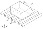
- FIG. 1 is a schematic diagram for explaining the structure of a container 10 including a vibration sensor module 1 according to an embodiment of the technique according to the present disclosure.
- FIG. 2 is a schematic diagram for explaining a method of transporting the container 10.
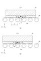
- FIG. 3 is a schematic diagram for explaining the state of the vibration sensor module 1 during transportation.
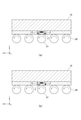
- FIG. 4 is a schematic diagram for explaining the principle of detecting an abnormality in the rotation speed of the roller 21.
- FIG. 5 is a schematic diagram for explaining the structure of the vibration sensor module 1A according to the first modification.
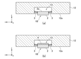
- FIG. 6 is a schematic diagram for explaining the structure of the vibration sensor module 1B according to the second modification.
- FIG. 7 is a schematic diagram for explaining the structure of the vibration sensor module 1C according to the third modification.
- FIG. 1 is a schematic diagram for explaining the structure of a container 10 including a vibration sensor module 1 according to an embodiment of the technique according to the present disclosure.
- the container 10 shown in FIG. 1 includes a main body portion 11 for accommodating luggage and a sensor holding portion 12 provided at the bottom of the main body portion 11.
- the sensor holding portion 12 has a bottom surface 12a in contact with the roller and a cavity 13 in which a part of the bottom surface 12a is hollowed out.
- the vibration sensor module 1 according to the present embodiment is arranged in the cavity 13.
- the vibration sensor module 1 is composed of a vibration sensor unit 2 that detects vibration and a support unit 3 that elastically supports the vibration sensor unit 2.
- the support portion 3 is composed of a plurality of springs.
- the spring may be a coil spring or a leaf spring.
- the container 10 having such a configuration is placed on a plurality of rollers 20 and conveyed in a predetermined direction by the rotation of the rollers 20.
- the plurality of rollers 20 come into contact with the bottom surface 12a of the container 10.
- the bottom surface 12a constitutes an xy surface.
- a plurality of rollers 20 having the y direction as the rotation axis are arranged in the x direction, and when the rollers 20 rotate counterclockwise, the container 10 is in the direction indicated by the arrow A (+ x direction). Will be transported to.
- FIG. 3 is a schematic diagram for explaining the state of the vibration sensor module 1 during transportation.
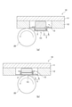
- the vibration sensor unit 2 constituting the vibration sensor module 1 is in a state where it is not in contact with any of the plurality of rollers 20, that is, in a state where an external force in the + z direction is not acting. , At least a part of the container 10 is elastically supported by the support portion 3 so as to project from the bottom surface 12a of the container 10 in the ⁇ z direction.
- FIG. 3B when the vibration sensor unit 2 comes into contact with any of the plurality of rollers 20, that is, when an external force in the + z direction is applied, the vibration sensor unit 2 is pushed up in the + z direction by the rollers 20. It is housed in the cavity 13. In this state, the bottom surface of the vibration sensor unit 2 in contact with the roller 20 forms the same plane as the bottom surface 12a of the container 10.
- the vibration sensor unit 2 it is not necessary to project the vibration sensor unit 2 from the cavity 13 when the vibration sensor module 1 is not used or measured, such as during transportation or storage, and a weight may be placed on the vibration sensor unit 2 during use, for example.
- a magnet may be arranged on the sensor holding portion 12 and the vibration sensor portion 2 may be projected by the repulsive force thereof.
- the vibration sensor unit 2 may be fixed with a stopper, and the vibration sensor unit 2 may be projected by removing the stopper at the time of use.
- the vibration sensor unit 2 comes into contact with the plurality of rollers 20 in sequence in conjunction with the transportation of the container 10. Then, when the predetermined roller 20 is rotating while vibrating due to an abnormality, this can be detected by the vibration sensor unit 2.
- the output signal of the vibration sensor unit 2 is supplied to the control circuit 30 shown in FIG. 1, and it is possible to detect that an abnormality has occurred in the predetermined roller 20.
- the vibration sensor module 1 and the control circuit 30 constitute an abnormality detection device for the container transport roller. In the example shown in FIG. 1, the control circuit 30 is provided in the container 10 itself, but this point is not essential in the present embodiment.
- the size L of the vibration sensor unit 2 in the x direction is designed to be smaller than the arrangement pitch P of the rollers 20, the vibration sensor unit 2 does not come into contact with the plurality of rollers 20 at the same time. Vibration can be selectively detected. Further, by ensuring a sufficient contact time between the roller 20 and the vibration sensor unit 2, the vibration generated in the roller 20 can be accurately detected. Therefore, the size L of the vibration sensor unit 2 in the x direction is preferably, for example, 50% or more, more preferably 80% or more of the arrangement pitch P of the rollers 20.
- the support portion 3 elastically supports the vibration sensor portion 2 so as to be displaceable in the x direction, which is the transport direction.
- the vibration sensor unit 2 is displaced in the ⁇ x direction.
- the rotation speed of the roller 21 is low, it depends on the spring characteristics of the support portion 3 and the frictional force between the roller 21 and the vibration sensor portion 2, but in general, the state shown in FIG. 4 (a) and FIG. 4 (b). The state shown in is repeated alternately. In this case, since the vibration sensor unit 2 vibrates in the x direction, it is possible to detect that an abnormality has occurred in the rotation speed of the roller 21 by detecting this state by the control circuit 30.
- the vibration sensor module 1 since the vibration sensor unit 2 directly detects the vibration and the rotation speed abnormality of the roller 20, it is determined which roller has the abnormality. Is possible.
- FIG. 5 is a schematic diagram for explaining the structure of the vibration sensor module 1A according to the first modification.
- a support portion 3 that elastically supports the vibration sensor portion 2 is provided in the x-direction and the y-direction, whereby the displacement characteristics in the x-direction and the displacement characteristics in the y-direction are mutually provided. Match.
- FIG. 6 is a schematic diagram for explaining the structure of the vibration sensor module 1B according to the second modification.
- the support portion 3 connecting the vibration sensor portion 2 and the sensor holding portion 12 in the z direction is omitted.
- the upper surface of the vibration sensor unit 2 constitutes the weight mounting portion 2a, and as shown in FIG. 6B, the weight 4 having an arbitrary weight can be mounted on the weight mounting portion 2a. If the vibration sensor module 1B having such a configuration is used, the vibration transmission characteristic between the vibration sensor unit 2 and the support unit 3 is changed by the weight 4, so that the vibration sensor unit 2 resonates due to the natural vibration of the container 10. It is possible to prevent the phenomenon of vibration.
- FIG. 7 is a schematic diagram for explaining the structure of the vibration sensor module 1C according to the third modification.
- the vibration sensor unit 2 is fixed to the saucer 5, and the cushion 6 is arranged between the vibration sensor unit 2 and the sensor holding unit 12.
- the saucer 5 comes into contact with the roller 20
- the saucer 5 is pushed up in the z direction as shown in FIG. 7B
- the cushion 6 contracts.
- the saucer 5 is separated from the roller 20, as shown in FIG. 7A
- the saucer 5 is in a state of protruding from the bottom surface 12a due to the restoring force of the cushion 6.
- the saucer 5 and the cushion 6 form the support portion 3.
- the support portion 3 is a spring.
- the vibration sensor unit 2 and the roller 20 come into direct contact with each other.
- Vibration sensor module 1A-1C Vibration sensor module 2 Vibration sensor part 2a Weight mounting part 3 Support part 4 Weight 5 Receiving tray 6 Cushion 10 Container 11 Main body part 12 Sensor holding part 12a Bottom 13 Cavity 20, 21 Roller 30 Control circuit
Landscapes
- Physics & Mathematics (AREA)
- General Physics & Mathematics (AREA)
- Control Of Conveyors (AREA)
- Measurement Of Mechanical Vibrations Or Ultrasonic Waves (AREA)
Abstract
【課題】コンテナ搬送用ローラーの異常を検出可能な振動センサーモジュールを提供する。 【解決手段】振動センサーモジュール1は、振動センサー部2と、振動センサー部2を弾性支持する支持部3とを備える。支持部3は、振動センサー部2が複数のローラー20のいずれにも接触していない状態においては、振動センサー部2の少なくとも一部がコンテナ10の底面12aから突出するよう振動センサー部2を支持し、振動センサー部2が複数のローラーのいずれかに接触している状態においては、振動センサー部2がキャビティ13に収容されるよう振動センサー部2を支持する。これにより、ローラー20の振動を振動センサー部2が直接検出することから、どのローラーに異常が生じているのか判定することが可能となる。
Description
本開示は振動センサーモジュールに関し、特に、複数のローラーが回転することによって搬送されるコンテナに取り付け可能な振動センサーモジュールに関する。また、本開示は、このような振動センサーモジュールを備えるコンテナ搬送用ローラーの異常検出装置に関する。
物流倉庫などにおいては、荷物を収容するコンテナが複数のローラー上に載置され、複数のローラーの回転によってコンテナが搬送される。このような物流倉庫においては、多数のローラーが常時回転しているため、一部のローラーに異常が生じることがある。また、上記のローラーの異常は、ローラーを回転させるモータの異常やモータシャフトとローラーを繋ぐベルトの異常によっても生じる。
ローラーの異常を検出する方法としては、コンテナに振動センサーを取り付けることによってローラーの異常な振動を検出する方法が考えられる。振動センサーとしては、特許文献1に記載された振動センサーが知られている。例えば、特許文献1に記載された振動センサーをコンテナに押し当てれば、コンテナに生じている振動を検出することができる。
しかしながら、搬送中のコンテナは複数のローラーに接触していることから、単にコンテナの振動を検出するだけでは、どのローラーに異常が生じているのか判別することができなかった。
したがって、本開示の目的の一つは、複数のローラーが回転することによって搬送されるコンテナに取り付け可能な振動センサーモジュールであって、どのローラーに異常が生じているのか判定可能な振動センサーモジュール及びこれを備えるコンテナ搬送用ローラーの異常検出装置を提供することである。
本開示に係る技術の一側面による振動センサーモジュールは、複数のローラーと接する底面にキャビティが設けられ、複数のローラーが回転することによって搬送されるコンテナに取り付けられる振動センサーモジュールであって、振動センサー部と、振動センサー部を弾性支持する支持部とを備え、支持部は、振動センサー部が複数のローラーのいずれにも接触していない状態においては、振動センサー部の少なくとも一部がコンテナの底面から突出するよう振動センサー部を支持し、振動センサー部が複数のローラーのいずれかに接触している状態においては、振動センサー部がキャビティに収容されるよう振動センサー部を支持するように構成可能である。
また、本開示に係る技術の一側面によるコンテナ搬送用ローラーの異常検出装置は、上記の振動センサーモジュールと、振動センサーモジュールの出力信号に基づいて、複数のローラーのいずれかに異常が生じていることを検出する制御回路とを備えるように構成可能である。
本開示に係る技術によれば、ローラーの振動を振動センサー部が直接検出することから、どのローラーに異常が生じているのか判定することが可能となる。
本開示において、振動センサー部の搬送方向におけるサイズは、搬送方向における複数のローラーの配列ピッチよりも小さくても構わない。これによれば、振動センサー部が複数のローラーと同時に接触することがないため、異常が生じているローラーを特定することが可能となる。
本開示において、支持部は、振動センサー部を底面と平行な方向に変位可能に弾性支持するものであっても構わない。これによれば、回転速度に異常が生じているローラーを検出することが可能となる。
本開示において、振動センサー部は、重錘を搭載可能な重錘搭載部を有するものであっても構わない。これによれば、振動センサー部と支持部の間の振動伝達特性を変化させることができる。
本開示に係る技術の他の側面による振動センサーモジュールは、キャビティ内に設けられた振動センサー部と、振動センサー部を弾性支持する支持部とを備え、支持部は、振動センサー部に所定方向の外力が作用していない状態においては、振動センサー部の少なくとも一部がキャビティから突出するよう振動センサー部を支持し、振動センサー部に所定方向の外力が作用している状態においては、振動センサー部がキャビティに収容されるよう振動センサー部を支持するように構成可能である。
本開示によれば、振動センサー部がフリーである状態においては、振動センサー部の少なくとも一部がキャビティから突出していることから、検出対象物と振動センサー部を確実に接触させることが可能となる。
このように、本開示にかかる技術によれば、どのローラーに異常が生じているのか判定可能となる。
以下、添付図面を参照しながら、本開示に係る技術の実施形態について詳細に説明する。
図1は、本開示に係る技術の一実施形態による振動センサーモジュール1を備えるコンテナ10の構造を説明するための模式図である。
図1に示すコンテナ10は、荷物を収容する本体部11と、本体部11の底部に設けられたセンサー保持部12を備えている。センサー保持部12は、ローラーと接する底面12aと、底面12aの一部がくり抜かれたキャビティ13を有している。そして、キャビティ13内に本実施形態による振動センサーモジュール1が配置される。振動センサーモジュール1は、振動を検出する振動センサー部2と、振動センサー部2を弾性支持する支持部3によって構成されている。図1に示す例では、支持部3が複数のバネによって構成されている。バネは、コイルバネであっても構わないし、板バネであっても構わない。
このような構成を有するコンテナ10は、図2に示すように、複数のローラー20に載置され、ローラー20の回転によって所定の方向に搬送される。搬送時においては、複数のローラー20とコンテナ10の底面12aが接触する。底面12aは、xy面を構成する。図2に示す例では、y方向を回転軸とする複数のローラー20がx方向に配列されており、ローラー20が反時計回りに回転することによってコンテナ10が矢印Aで示す方向(+x方向)に搬送される。
図3は、搬送時における振動センサーモジュール1の状態を説明するための模式図である。
図3(a)に示すように、振動センサーモジュール1を構成する振動センサー部2は、複数のローラー20のいずれにも接触していない状態、つまり+z方向の外力が作用していない状態においては、少なくとも一部がコンテナ10の底面12aから-z方向に突出するよう、支持部3によって弾性支持されている。一方、図3(b)に示すように、振動センサー部2が複数のローラー20のいずれかと接触すると、つまり+z方向の外力が作用すると、ローラー20によって振動センサー部2が+z方向に押し上げられ、キャビティ13に収容される。この状態においては、ローラー20と接触する振動センサー部2の底面は、コンテナ10の底面12aと同一平面を構成する。
但し、振動センサーモジュール1の輸送時や保管時等の未使用時や非測定時には、振動センサー部2をキャビティ13から突出させておく必要はなく、使用時に例えば振動センサー部2に重りを載せたり、或いは、センサー保持部12に磁石を配置してその反発力で振動センサー部2を突出させたりしても構わない。また、振動センサー部2をストッパーで固定しておき、使用時にストッパーを外すことによって振動センサー部2を突出させても構わない。
このような動作により、コンテナ10の搬送と連動して振動センサー部2が複数のローラー20と順次接触することになる。そして、所定のローラー20が異常により振動しながら回転している場合、これを振動センサー部2によって検出することができる。振動センサー部2の出力信号は図1に示す制御回路30に供給され、これにより所定のローラー20に異常が生じていることを検出することができる。振動センサーモジュール1と制御回路30は、コンテナ搬送用ローラーの異常検出装置を構成する。図1に示す例では、制御回路30がコンテナ10自体に設けられているが、本実施形態においてこの点は必須ではない。
ここで、振動センサー部2のx方向におけるサイズLをローラー20の配列ピッチPよりも小さく設計すれば、振動センサー部2が複数のローラー20と同時に接触することがないため、個々のローラー20の振動を選択的に検出することが可能となる。また、ローラー20と振動センサー部2の接触時間を十分に確保することで、ローラー20に生じている振動を正確に検出することができる。このため、振動センサー部2のx方向におけるサイズLは、例えば、ローラー20の配列ピッチPの50%以上であることが好ましく、80%以上であることがより好ましい。
また、本実施形態においては、支持部3が振動センサー部2を搬送方向であるx方向に変位可能に弾性支持している。これにより、ローラー20の振動だけでなく、ローラー20の回転速度異常についても検出することができる。例えば、図4(a)に示すローラー21に異常が生じ、他のローラー20よりも回転速度が低下している場合、ローラー21と振動センサー部2が接触すると、図4(b)に示すように振動センサー部2が-x方向に変位する。ローラー21の回転速度が低下している場合、支持部3のバネ特性やローラー21と振動センサー部2の摩擦力にも依るが、一般に、図4(a)に示す状態と図4(b)に示す状態を交互に繰り返す。この場合、振動センサー部2はx方向に振動することから、この状態を制御回路30が検出することより、ローラー21の回転速度に異常が生じていることを検出することができる。
以上説明したように、本実施形態による振動センサーモジュール1によれば、ローラー20の振動や回転速度異常を振動センサー部2が直接検出することから、どのローラーに異常が生じているのか判定することが可能となる。
図5は、第1の変形例による振動センサーモジュール1Aの構造を説明するための模式図である。図5に示す振動センサーモジュール1Aは、振動センサー部2を弾性支持する支持部3がx方向及びy方向に設けられており、これにより、x方向における変位特性と、y方向における変位特性が互いに一致している。このような構成を有する振動センサーモジュール1Aを用いれば、コンテナ10の搬送方向に関わらず、ローラー20の異常を正しく検出することが可能となる。つまり、コンテナ10がx方向及びy方向のいずれの方向に搬送される場合であっても、ローラー20の異常を検出することが可能となる。
図6は、第2の変形例による振動センサーモジュール1Bの構造を説明するための模式図である。図6(a)に示す振動センサーモジュール1Bは、振動センサー部2とセンサー保持部12をz方向に接続する支持部3が省略されている。振動センサー部2の上面は重錘搭載部2aを構成し、図6(b)に示すように、重錘搭載部2aに任意の重さを有する重錘4を搭載することができる。このような構成を有する振動センサーモジュール1Bを用いれば、振動センサー部2と支持部3の間の振動伝達特性が重錘4によって変化することから、コンテナ10の固有振動によって振動センサー部2が共振する現象を防止することが可能となる。
図7は、第3の変形例による振動センサーモジュール1Cの構造を説明するための模式図である。図7(a)に示す振動センサーモジュール1Cは、振動センサー部2が受け皿5に固定されているとともに、振動センサー部2とセンサー保持部12の間にクッション6が配置されている。これにより、受け皿5がローラー20と接触すると、図7(b)に示すように受け皿5がz方向に押し上げられ、クッション6が収縮する。そして、受け皿5がローラー20から離れると、図7(a)に示すように、クッション6の復元力によって受け皿5が底面12aから突出した状態となる。本例においては、受け皿5及びクッション6が支持部3を構成する。このように、支持部3がバネである点は必須ではない。また、振動センサー部2とローラー20が直接接触する点も必須ではない。
以上、本開示に係る技術の実施形態について説明した。本開示に係る技術は、上記の実施形態に限定されることなく、その主旨を逸脱しない範囲で種々の変更が可能であり、それらも本開示に係る技術の範囲内に包含されるものであることはいうまでもない。なお、本開示は、2020年7月27日に日本国特許庁に出願された特願2020-126128号に対する優先権の利益を主張し、上記特許出願の内容全体を参照により本明細書に援用する。
1,1A~1C 振動センサーモジュール
2 振動センサー部
2a 重錘搭載部
3 支持部
4 重錘
5 受け皿
6 クッション
10 コンテナ
11 本体部
12 センサー保持部
12a 底面
13 キャビティ
20,21 ローラー
30 制御回路
2 振動センサー部
2a 重錘搭載部
3 支持部
4 重錘
5 受け皿
6 クッション
10 コンテナ
11 本体部
12 センサー保持部
12a 底面
13 キャビティ
20,21 ローラー
30 制御回路
Claims (6)
- 複数のローラーと接する底面にキャビティが設けられ、前記複数のローラーが回転することによって搬送されるコンテナに取り付けられる振動センサーモジュールであって、
振動センサー部と、
前記振動センサー部を弾性支持する支持部と、を備え、
前記支持部は、前記振動センサー部が前記複数のローラーのいずれにも接触していない状態においては、前記振動センサー部の少なくとも一部が前記コンテナの前記底面から突出するよう前記振動センサー部を支持し、前記振動センサー部が前記複数のローラーのいずれかに接触している状態においては、前記振動センサー部が前記キャビティに収容されるよう前記振動センサー部を支持することを特徴とする振動センサーモジュール。 - 前記振動センサー部の搬送方向におけるサイズは、前記搬送方向における前記複数のローラーの配列ピッチよりも小さいことを特徴とする請求項1に記載の振動センサーモジュール。
- 前記支持部は、前記振動センサー部を前記底面と平行な方向に変位可能に弾性支持することを特徴とする請求項1又は2に記載の振動センサーモジュール。
- 前記振動センサー部は、重錘を搭載可能な重錘搭載部を有することを特徴とする請求項1乃至3のいずれか一項に記載の振動センサーモジュール。
- 請求項1乃至4のいずれか一項に記載の振動センサーモジュールと、
前記振動センサーモジュールの出力信号に基づいて、前記複数のローラーのいずれかに異常が生じていることを検出する制御回路と、を備えることを特徴とするコンテナ搬送用ローラーの異常検出装置。 - キャビティ内に設けられた振動センサー部と、
前記振動センサー部を弾性支持する支持部と、を備え、
前記支持部は、前記振動センサー部に所定方向の外力が作用していない状態においては、前記振動センサー部の少なくとも一部が前記キャビティから突出するよう前記振動センサー部を支持し、前記振動センサー部に前記所定方向の外力が作用している状態においては、前記振動センサー部が前記キャビティに収容されるよう前記振動センサー部を支持することを特徴とする振動センサーモジュール。
Priority Applications (2)
| Application Number | Priority Date | Filing Date | Title |
|---|---|---|---|
| JP2021561947A JP7035285B1 (ja) | 2020-07-27 | 2021-06-30 | 振動センサーモジュール及びこれを備えるコンテナ搬送用ローラーの異常検出装置 |
| JP2022031527A JP7356745B2 (ja) | 2020-07-27 | 2022-03-02 | 振動センサーモジュール及びこれを備えるコンテナ |
Applications Claiming Priority (2)
| Application Number | Priority Date | Filing Date | Title |
|---|---|---|---|
| JP2020-126128 | 2020-07-27 | ||
| JP2020126128 | 2020-07-27 |
Publications (1)
| Publication Number | Publication Date |
|---|---|
| WO2022024643A1 true WO2022024643A1 (ja) | 2022-02-03 |
Family
ID=80035497
Family Applications (1)
| Application Number | Title | Priority Date | Filing Date |
|---|---|---|---|
| PCT/JP2021/024678 Ceased WO2022024643A1 (ja) | 2020-07-27 | 2021-06-30 | 振動センサーモジュール及びこれを備えるコンテナ搬送用ローラーの異常検出装置 |
Country Status (2)
| Country | Link |
|---|---|
| JP (2) | JP7035285B1 (ja) |
| WO (1) | WO2022024643A1 (ja) |
Citations (4)
| Publication number | Priority date | Publication date | Assignee | Title |
|---|---|---|---|---|
| JPS60183832U (ja) * | 1984-05-17 | 1985-12-06 | 日本鉱業株式会社 | 振動測定装置 |
| JPH0718225U (ja) * | 1993-09-13 | 1995-03-31 | 三菱重工業株式会社 | 非破壊検査装置 |
| JP2010189166A (ja) * | 2009-02-19 | 2010-09-02 | Bridgestone Corp | コンベヤベルト及びガイドローラの不良判定システム |
| JP2016204120A (ja) * | 2015-04-23 | 2016-12-08 | 三菱電機株式会社 | 乗客コンベアの異常診断装置および乗客コンベアの異常診断方法 |
Family Cites Families (6)
| Publication number | Priority date | Publication date | Assignee | Title |
|---|---|---|---|---|
| US3859847A (en) * | 1972-09-06 | 1975-01-14 | Westinghouse Electric Corp | Vibration monitoring device using accelerometer to measure displacement |
| JPS60242322A (ja) * | 1984-12-21 | 1985-12-02 | Mitsubishi Electric Corp | 軸振動検出器 |
| JP3058779B2 (ja) * | 1993-03-13 | 2000-07-04 | オート株式会社 | 筆記状態測定方法および装置 |
| US6129025A (en) * | 1995-07-04 | 2000-10-10 | Minakami; Hiroyuki | Traffic/transportation system |
| JPH10153479A (ja) * | 1996-11-25 | 1998-06-09 | Hitachi Ltd | 手持ち式非接触振動測定器 |
| JP6446116B1 (ja) * | 2017-11-27 | 2018-12-26 | トーヨーカネツソリューションズ株式会社 | 搬送システム検査装置 |
-
2021
- 2021-06-30 JP JP2021561947A patent/JP7035285B1/ja active Active
- 2021-06-30 WO PCT/JP2021/024678 patent/WO2022024643A1/ja not_active Ceased
-
2022
- 2022-03-02 JP JP2022031527A patent/JP7356745B2/ja active Active
Patent Citations (4)
| Publication number | Priority date | Publication date | Assignee | Title |
|---|---|---|---|---|
| JPS60183832U (ja) * | 1984-05-17 | 1985-12-06 | 日本鉱業株式会社 | 振動測定装置 |
| JPH0718225U (ja) * | 1993-09-13 | 1995-03-31 | 三菱重工業株式会社 | 非破壊検査装置 |
| JP2010189166A (ja) * | 2009-02-19 | 2010-09-02 | Bridgestone Corp | コンベヤベルト及びガイドローラの不良判定システム |
| JP2016204120A (ja) * | 2015-04-23 | 2016-12-08 | 三菱電機株式会社 | 乗客コンベアの異常診断装置および乗客コンベアの異常診断方法 |
Also Published As
| Publication number | Publication date |
|---|---|
| JP7356745B2 (ja) | 2023-10-05 |
| JPWO2022024643A1 (ja) | 2022-02-03 |
| JP7035285B1 (ja) | 2022-03-14 |
| JP2022075721A (ja) | 2022-05-18 |
Similar Documents
| Publication | Publication Date | Title |
|---|---|---|
| CN114161394A (zh) | 具有操纵机构的机器人系统和其操作方法 | |
| CN105121315B (zh) | 片材进给装置及图像形成装置 | |
| CN104411610B (zh) | 重叠进给检测装置以及板状物处理装置 | |
| JP7035285B1 (ja) | 振動センサーモジュール及びこれを備えるコンテナ搬送用ローラーの異常検出装置 | |
| JP4929918B2 (ja) | 複合センサ | |
| CN109573673B (zh) | 介质传送装置、图像读取装置及记录装置 | |
| JP2009012959A (ja) | 媒体給送装置 | |
| CN113634522B (zh) | 货物传送装置、方法、电子设备和计算机可读介质 | |
| CN110944846B (zh) | 介质检测器 | |
| JP5810796B2 (ja) | ワーク分別搬送装置 | |
| JP6447282B2 (ja) | 光書込み装置及び画像形成装置 | |
| TWI557047B (zh) | An oscillating type detecting device for an electronic component holder and a working device for its application | |
| JP5168999B2 (ja) | 部品搬送装置 | |
| JP2627266B2 (ja) | 搬送アーム | |
| US20250128888A1 (en) | Transport device for transporting products, and method for transporting products by means of a transport device | |
| KR100985608B1 (ko) | 소형모터의 잡음 측정장치 | |
| CN113844859B (zh) | 一种机械式皮带打滑检测装置 | |
| JP2006284450A (ja) | 車両部品の加速度判定装置およびその装置を含む車両部品の搬送用梱包材 | |
| JP2019172413A (ja) | 厚み検知装置 | |
| JPWO2005052601A1 (ja) | 加速度検出装置 | |
| JP6362380B2 (ja) | 電子機器 | |
| JP2004325171A (ja) | 耐振動エンコーダ | |
| JPS6190946A (ja) | 電子複写機の搬送装置 | |
| JPH0727603A (ja) | 可動部の異常振動検査装置 | |
| JP2016113270A (ja) | 搬送装置 |
Legal Events
| Date | Code | Title | Description |
|---|---|---|---|
| ENP | Entry into the national phase |
Ref document number: 2021561947 Country of ref document: JP Kind code of ref document: A |
|
| 121 | Ep: the epo has been informed by wipo that ep was designated in this application |
Ref document number: 21849233 Country of ref document: EP Kind code of ref document: A1 |
|
| NENP | Non-entry into the national phase |
Ref country code: DE |
|
| 122 | Ep: pct application non-entry in european phase |
Ref document number: 21849233 Country of ref document: EP Kind code of ref document: A1 |