WO2022024622A1 - 変倍光学系、光学機器、および変倍光学系の製造方法 - Google Patents
変倍光学系、光学機器、および変倍光学系の製造方法 Download PDFInfo
- Publication number
- WO2022024622A1 WO2022024622A1 PCT/JP2021/024061 JP2021024061W WO2022024622A1 WO 2022024622 A1 WO2022024622 A1 WO 2022024622A1 JP 2021024061 W JP2021024061 W JP 2021024061W WO 2022024622 A1 WO2022024622 A1 WO 2022024622A1
- Authority
- WO
- WIPO (PCT)
- Prior art keywords
- lens group
- optical system
- focusing
- lens
- variable magnification
- Prior art date
- Legal status (The legal status is an assumption and is not a legal conclusion. Google has not performed a legal analysis and makes no representation as to the accuracy of the status listed.)
- Ceased
Links
Images












Classifications
-
- G—PHYSICS
- G02—OPTICS
- G02B—OPTICAL ELEMENTS, SYSTEMS OR APPARATUS
- G02B15/00—Optical objectives with means for varying the magnification
- G02B15/14—Optical objectives with means for varying the magnification by axial movement of one or more lenses or groups of lenses relative to the image plane for continuously varying the equivalent focal length of the objective
- G02B15/16—Optical objectives with means for varying the magnification by axial movement of one or more lenses or groups of lenses relative to the image plane for continuously varying the equivalent focal length of the objective with interdependent non-linearly related movements between one lens or lens group, and another lens or lens group
-
- G—PHYSICS
- G02—OPTICS
- G02B—OPTICAL ELEMENTS, SYSTEMS OR APPARATUS
- G02B13/00—Optical objectives specially designed for the purposes specified below
- G02B13/18—Optical objectives specially designed for the purposes specified below with lenses having one or more non-spherical faces, e.g. for reducing geometrical aberration
-
- G—PHYSICS
- G02—OPTICS
- G02B—OPTICAL ELEMENTS, SYSTEMS OR APPARATUS
- G02B15/00—Optical objectives with means for varying the magnification
- G02B15/14—Optical objectives with means for varying the magnification by axial movement of one or more lenses or groups of lenses relative to the image plane for continuously varying the equivalent focal length of the objective
- G02B15/146—Optical objectives with means for varying the magnification by axial movement of one or more lenses or groups of lenses relative to the image plane for continuously varying the equivalent focal length of the objective having more than five groups
- G02B15/1461—Optical objectives with means for varying the magnification by axial movement of one or more lenses or groups of lenses relative to the image plane for continuously varying the equivalent focal length of the objective having more than five groups the first group being positive
-
- G—PHYSICS
- G02—OPTICS
- G02B—OPTICAL ELEMENTS, SYSTEMS OR APPARATUS
- G02B15/00—Optical objectives with means for varying the magnification
- G02B15/14—Optical objectives with means for varying the magnification by axial movement of one or more lenses or groups of lenses relative to the image plane for continuously varying the equivalent focal length of the objective
- G02B15/16—Optical objectives with means for varying the magnification by axial movement of one or more lenses or groups of lenses relative to the image plane for continuously varying the equivalent focal length of the objective with interdependent non-linearly related movements between one lens or lens group, and another lens or lens group
- G02B15/177—Optical objectives with means for varying the magnification by axial movement of one or more lenses or groups of lenses relative to the image plane for continuously varying the equivalent focal length of the objective with interdependent non-linearly related movements between one lens or lens group, and another lens or lens group having a negative front lens or group of lenses
-
- G—PHYSICS
- G02—OPTICS
- G02B—OPTICAL ELEMENTS, SYSTEMS OR APPARATUS
- G02B15/00—Optical objectives with means for varying the magnification
- G02B15/14—Optical objectives with means for varying the magnification by axial movement of one or more lenses or groups of lenses relative to the image plane for continuously varying the equivalent focal length of the objective
- G02B15/16—Optical objectives with means for varying the magnification by axial movement of one or more lenses or groups of lenses relative to the image plane for continuously varying the equivalent focal length of the objective with interdependent non-linearly related movements between one lens or lens group, and another lens or lens group
- G02B15/20—Optical objectives with means for varying the magnification by axial movement of one or more lenses or groups of lenses relative to the image plane for continuously varying the equivalent focal length of the objective with interdependent non-linearly related movements between one lens or lens group, and another lens or lens group having an additional movable lens or lens group for varying the objective focal length
Definitions
- the present invention relates to a variable magnification optical system, an optical device, and a method for manufacturing the variable magnification optical system.
- variable magnification optical systems suitable for photographic cameras, electronic still cameras, video cameras, etc. have been proposed (see, for example, Patent Document 1).
- it is difficult to suppress aberration fluctuations during focusing.
- the variable magnification optical system includes a front lens group having a positive refractive force, a first intermediate lens group having a negative refractive force, and a positive refractive force arranged in order from the object side along the optical axis.
- the second intermediate lens group and the succeeding lens group have a The first focusing lens group that moves along the optical axis during focusing and the first focusing lens that is arranged on the image side of the first focusing lens group and moves along the optical axis during focusing. It includes at least one other in-focus lens group that moves along the optical axis in a trajectory different from the group, and satisfies the following conditional expression.
- fFs the focal length of the focusing lens group having the strongest refractive power among the focusing lens groups included in the succeeding lens group
- fFy the focal length of the focusing lens group having the weakest refractive power among the focusing lens groups included in the succeeding lens group.
- Focal length of the focal lens group f1 Focal length of the front lens group
- fw Focal length of the variable magnification optical system in the wide-angle end state
- the optical device according to the present invention is configured to include the above-mentioned variable magnification optical system.
- the method for manufacturing a variable magnification optical system according to the present invention includes a front lens group having a positive refractive force, a first intermediate lens group having a negative refractive force, and a positive lens group arranged in order from the object side along the optical axis.
- This is a method for manufacturing a variable magnification optical system having a second intermediate lens group having a refractive power of the same as that of a subsequent lens group. Is arranged on the most object side of the subsequent lens group, and is arranged on the image side of the first in-focus lens group and the first in-focus lens group that move along the optical axis during focusing.
- the lens barrel includes at least one other in-focus lens group that moves along the optical axis in a trajectory different from that of the first in-focus lens group at the time of focusing, and satisfies the following conditional expression. Place each lens inside. -0.37 ⁇ fFs / fFy ⁇ 0.37 2.00 ⁇ f1 / fw ⁇ 8.00 However, fFs: the focal length of the focusing lens group having the strongest refractive power among the focusing lens groups included in the succeeding lens group fFy: the focal length of the focusing lens group having the weakest refractive power among the focusing lens groups included in the succeeding lens group.
- Focal length of the focal lens group f1 Focal length of the front lens group
- fw Focal length of the variable magnification optical system in the wide-angle end state
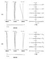
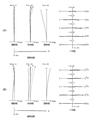
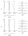
- 5 (A) and 5 (B) are aberration diagrams at infinity focusing in the wide-angle end state and the telephoto end state of the variable magnification optical system according to the second embodiment, respectively.
- 6 (A) and 6 (B) are aberration diagrams at short-distance focusing in the wide-angle end state and the telephoto end state of the variable magnification optical system according to the second embodiment, respectively. It is a figure which shows the lens structure of the variable magnification optical system which concerns on 3rd Example.
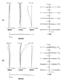
- 8 (A) and 8 (B) are aberration diagrams at infinity focusing in the wide-angle end state and the telephoto end state of the variable magnification optical system according to the third embodiment, respectively.
- 9 (A) and 9 (B) are aberration diagrams at short-distance focusing in the wide-angle end state and the telephoto end state of the variable magnification optical system according to the third embodiment, respectively. It is a figure which shows the lens structure of the variable magnification optical system which concerns on 4th Embodiment.
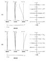
- 11 (A) and 11 (B) are aberration diagrams at infinity focusing in the wide-angle end state and the telephoto end state of the variable magnification optical system according to the fourth embodiment, respectively.
- 12 (A) and 12 (B) are aberration diagrams at short-distance focusing in the wide-angle end state and the telephoto end state of the variable magnification optical system according to the fourth embodiment, respectively.
- FIG. 14 (A) and 14 (B) are aberration diagrams at infinity focusing in the wide-angle end state and the telephoto end state of the variable magnification optical system according to the fifth embodiment, respectively.
- 15 (A) and 15 (B) are aberration diagrams at short-distance focusing in the wide-angle end state and the telephoto end state of the variable magnification optical system according to the fifth embodiment, respectively.
- 17 (A) and 17 (B) are aberration diagrams at infinity focusing in the wide-angle end state and the telephoto end state of the variable magnification optical system according to the sixth embodiment, respectively.
- 18 (A) and 18 (B) are aberration diagrams at short-distance focusing in the wide-angle end state and the telephoto end state of the variable magnification optical system according to the sixth embodiment, respectively. It is a figure which shows the lens structure of the variable magnification optical system which concerns on 7th Example.
- 20 (A) and 20 (B) are aberration diagrams at infinity focusing in the wide-angle end state and the telephoto end state of the variable magnification optical system according to the seventh embodiment, respectively.
- 21 (A) and 21 (B) are aberration diagrams at short-distance focusing in the wide-angle end state and the telephoto end state of the variable magnification optical system according to the seventh embodiment, respectively. It is a figure which shows the structure of the camera provided with the variable magnification optical system which concerns on this embodiment. It is a flowchart which shows the manufacturing method of the variable magnification optical system which concerns on this embodiment.
- the camera 1 includes a main body 2 and a photographing lens 3 mounted on the main body 2.
- the main body 2 includes an image sensor 4, a main body control unit (not shown) that controls the operation of a digital camera, and a liquid crystal screen 5.
- the photographing lens 3 includes a variable magnification optical system ZL composed of a plurality of lens groups and a lens position control mechanism (not shown) for controlling the position of each lens group.
- the lens position control mechanism includes a sensor that detects the position of the lens group, a motor that moves the lens group back and forth along the optical axis, a control circuit that drives the motor, and the like.
- variable magnification optical system ZL of the photographing lens 3 The light from the subject is focused by the variable magnification optical system ZL of the photographing lens 3 and reaches the image plane I of the image pickup element 4.
- the light from the subject that has reached the image plane I is photoelectrically converted by the image pickup device 4 and recorded as digital image data in a memory (not shown).
- the digital image data recorded in the memory can be displayed on the liquid crystal screen 5 according to the operation of the user.
- This camera may be a mirrorless camera or a single-lens reflex type camera having a quick return mirror.
- the variable magnification optical system ZL shown in FIG. 22 schematically shows the variable magnification optical system provided in the photographing lens 3, and the lens configuration of the variable magnification optical system ZL is not limited to this configuration. No.
- variable-magnification optical system ZL (1) as an example of the variable-magnification optical system (zoom lens) ZL according to the present embodiment has positive refractive powers arranged in order from the object side along the optical axis. It is composed of a front lens group GA having a force, a first intermediate lens group GM1 having a negative refractive power, a second intermediate lens group GM2 having a positive refractive power, and a succeeding lens group GR. At the time of scaling, the distance between adjacent lens groups changes.
- the trailing lens group GR is arranged on the most object side of the trailing lens group GR, and is an image from the first focusing lens group GF1 and the first focusing lens group GF1 that move along the optical axis during focusing. Includes at least one other in-focus lens group that is located on the side and moves along the optical axis in a trajectory different from that of the first in-focus lens group GF1 during in-focus.
- variable magnification optical system ZL satisfies the following conditional expression (1) and conditional expression (2).
- conditional expression (1) conditional expression (2).
- fFs the focal length of the focusing lens group having the strongest refractive power among the focusing lens groups included in the succeeding lens group
- GR fFy the focal length of the focusing lens group included in the succeeding lens group GR having the weakest refractive power.
- Focal length of the focal lens group f1 Focal length of the front lens group
- GA fw Focal length of the variable magnification optical system ZL in the wide-angle end state
- variable magnification optical system having less aberration fluctuation during focusing and an optical device provided with this variable magnification optical system. Since the succeeding lens group GR has a plurality of focusing lens groups, it is possible to suppress fluctuations in various aberrations such as spherical aberration during focusing without increasing the size of the focusing lens group. Further, by changing the distance between adjacent lens groups at the time of scaling, it is possible to satisfactorily correct the aberration at the time of scaling.
- variable-magnification optical system ZL may be the variable-magnification optical system ZL (2) shown in FIG. 4, the variable-magnification optical system ZL (3) shown in FIG. 7, and the variable-magnification optical system shown in FIG. ZL (4) may be used. Further, the variable magnification optical system ZL according to the present embodiment may be the variable magnification optical system ZL (5) shown in FIG. 13, the variable magnification optical system ZL (6) shown in FIG. 16, or the variable magnification optical system ZL (6) shown in FIG. The optical system ZL (7) may be used.
- the focal length of the focusing lens group having the strongest refractive power among the focusing lens groups included in the succeeding lens group GR and the focal length of the focusing lens group included in the succeeding lens group GR are used.
- the corresponding value of the conditional expression (1) exceeds the upper limit value, the difference in the refractive power between the in-focus lens group having the strongest refractive power and the in-focus lens group having the weakest refractive power becomes small. It becomes difficult to suppress fluctuations in various aberrations such as spherical aberration.
- the upper limit of the conditional expression (1) By setting the upper limit of the conditional expression (1) to 0.35, 0.30, 0.28, 0.26, 0.20, 0.18, and further 0.15, the effect of the present embodiment can be obtained. It can be made more reliable.
- the lower limit of the conditional expression (1) is set to -0.35, -0.30, -0.25, -0.20, -1.50, -1.00, -0.50, -0.30, Further, by setting it to ⁇ 0.10, the effect of the present embodiment can be further ensured.
- Conditional expression (2) defines an appropriate relationship between the focal length of the front lens group GA and the focal length of the variable magnification optical system ZL in the wide-angle end state. By satisfying the conditional expression (2), it is possible to suppress fluctuations in various aberrations such as spherical aberration during scaling without increasing the size of the lens barrel.
- the refractive power of the front lens group GA becomes weak, so that the amount of movement of the front lens group GA at the time of scaling increases and the lens barrel becomes large.
- the refractive power of the front lens group GA becomes strong, so that it becomes difficult to suppress fluctuations of various aberrations such as spherical aberration at the time of scaling.
- variable magnification optical system ZL satisfies the following conditional expression (3). -6.00 ⁇ fFs / fw ⁇ 6.00 ... (3)
- Conditional expression (3) is appropriate for the focal length of the focusing lens group having the strongest refractive power among the focusing lens groups included in the succeeding lens group GR and the focal length of the variable magnification optical system ZL in the wide-angle end state. It defines the relationship. By satisfying the conditional expression (3), it is possible to suppress fluctuations in various aberrations such as spherical aberration during focusing.
- the corresponding value of the conditional expression (3) exceeds the upper limit value, the difference in the refractive power between the in-focus lens group having the strongest refractive power and the in-focus lens group having the weakest refractive power becomes small. It becomes difficult to suppress fluctuations in various aberrations such as spherical aberration.
- the upper limit of the conditional expression (3) to 5.50, 5.00, 4.80, 4.50, 4.00, and further 3.80, the effect of this embodiment is more reliable. Can be.
- the refractive power of the focusing lens group having the strongest refractive power becomes strong, so that fluctuations of various aberrations such as spherical aberration during focusing should be suppressed. Becomes difficult.
- the lower limit of the conditional expression (3) is set to -5.50, -5.00, -4.50, -4.00, -3.50, -3.00, -2.50, -2.00, Further, by setting it to -1.80, the effect of this embodiment can be further ensured.
- variable magnification optical system ZL satisfies the following conditional expression (4). 4.30 ⁇ f1 / (-fM1w) ⁇ 10.00 ... (4)
- fM1w the focal length of the first intermediate lens group GM1 in the wide-angle end state.
- Conditional expression (4) defines an appropriate relationship between the focal length of the front lens group GA and the focal length of the first intermediate lens group GM1 in the wide-angle end state.
- the refractive power of the first intermediate lens group GM1 becomes stronger, so that it becomes difficult to suppress fluctuations of various aberrations such as spherical aberration at the time of scaling. Become.
- the upper limit of the conditional expression (4) to 9.50, 9.00, 8.80, 8.50, 8.30, 8.00, and further 7.80, the effect of this embodiment can be obtained. It can be made more reliable.
- the refractive power of the front lens group GA becomes strong, so that it becomes difficult to suppress fluctuations of various aberrations such as spherical aberration at the time of scaling.
- the second intermediate lens group GM2 includes a lens group having at least two positive refractive powers, and it is desirable that the following conditional expression (5) is satisfied. 1.50 ⁇ f1 / fM21 ⁇ 7.00 ... (5)
- fM21 the focal length of the lens group on the most object side among the lens groups included in the second intermediate lens group GM2.
- Conditional expression (5) defines an appropriate relationship between the focal length of the front lens group GA and the focal length of the lens group on the most object side among the lens groups included in the second intermediate lens group GM2. By satisfying the conditional expression (5), it is possible to suppress fluctuations in various aberrations such as spherical aberration during focusing.
- the refractive power of the lens group on the object side among the lens groups included in the second intermediate lens group GM2 becomes stronger, so that spherical aberration during focusing is caused. It becomes difficult to suppress fluctuations in various aberrations including the above.
- the refractive power of the front lens group GA becomes strong, so that it becomes difficult to suppress fluctuations of various aberrations such as spherical aberration during focusing.
- variable magnification optical system ZL satisfies the following conditional expression (6). 0.10 ⁇ BFw / fw ⁇ 1.00 ... (6)
- BFw the back focus of the variable magnification optical system ZL in the wide-angle end state.
- Conditional expression (6) defines an appropriate relationship between the back focus of the variable magnification optical system ZL in the wide-angle end state and the focal length of the variable magnification optical system ZL in the wide-angle end state.
- the back focus of the variable magnification optical system ZL in the wide-angle end state becomes larger than the focal length of the variable magnification optical system ZL in the wide-angle end state, so that the wide-angle end It becomes difficult to correct various aberrations such as coma in the state.
- This implementation is performed by setting the upper limit of the conditional expression (6) to 0.95, 0.90, 0.85, 0.80, 0.75, 0.70, 0.65, and further 0.60. The effect of the morphology can be made more certain.
- the corresponding value of the conditional expression (6) is less than the lower limit, the back focus of the variable magnification optical system ZL in the wide-angle end state becomes smaller than the focal length of the variable magnification optical system ZL in the wide-angle end state, so that the wide-angle end It becomes difficult to correct various aberrations such as coma in the state. In addition, it becomes difficult to arrange the mechanical member of the lens barrel.
- the lower limit of the conditional expression (6) By setting the lower limit of the conditional expression (6) to 0.15, 0.25, 0.25, 0.30, 0.35, 0.40, and further 0.43, the effect of the present embodiment can be obtained. It can be made more reliable.
- variable magnification optical system ZL satisfies the following conditional expression (7). 0.20 ⁇
- Conditional expression (7) defines an appropriate relationship between the focal length of the focusing lens group having the strongest refractive power among the focusing lens groups included in the succeeding lens group GR and the focal length of the front lens group GA. Is.
- the refractive power of the focusing lens group becomes weak, so that the amount of movement of the focusing lens group at the time of focusing becomes large and the lens barrel becomes large. Further, since the refractive power of the front lens group GA becomes strong, it becomes difficult to suppress fluctuations of various aberrations such as spherical aberration at the time of scaling.
- the upper limit of the conditional expression (7) is set to 1.80, 1.50, 1.30, 1.00, 0.85, 0.70, 0.65, 0.60, and further 0.58. Therefore, the effect of this embodiment can be made more certain.
- the refractive power of the focusing lens group becomes strong, so that it becomes difficult to suppress fluctuations of various aberrations such as spherical aberration during focusing. Further, since the refractive power of the front lens group GA is weakened, the amount of movement of the front lens group GA at the time of scaling becomes large, and the lens barrel becomes large.
- variable magnification optical system ZL satisfies the following conditional expression (8). 1.50 ⁇
- fM1w the focal length of the first intermediate lens group GM1 in the wide-angle end state.
- Conditional expression (8) is appropriate for the focal length of the focusing lens group having the strongest refractive power among the focusing lens groups included in the succeeding lens group GR and the focal length of the first intermediate lens group GM1 in the wide-angle end state. It defines the relationship.
- conditional expression (8) it is possible to suppress fluctuations in various aberrations such as spherical aberration during focusing.
- various aberrations such as coma in the wide-angle end state can be satisfactorily corrected.
- the refractive power of the first intermediate lens group GM1 in the wide-angle end state becomes strong, so that various aberrations such as coma aberration in the wide-angle end state can be corrected. It will be difficult.
- the refractive power of the focusing lens group becomes strong, so that it becomes difficult to suppress fluctuations of various aberrations such as spherical aberration during focusing.
- the lower limit of the conditional expression (8) 1.55, 1.60, 1.65, 1.70, 1.75, 1.80, and further 1.83, the effect of this embodiment can be obtained. It can be made more reliable.
- variable magnification optical system ZL satisfies the following conditional expression (9). 0.90 ⁇
- fM2w the focal length of the second intermediate lens group GM2 in the wide-angle end state.
- Conditional expression (9) is appropriate for the focal length of the focusing lens group having the strongest refractive power among the focusing lens groups included in the succeeding lens group GR and the focal length of the second intermediate lens group GM2 in the wide-angle end state. It defines the relationship.
- conditional equation (9) it is possible to suppress fluctuations in various aberrations such as spherical aberration during focusing.
- various aberrations such as coma in the wide-angle end state can be satisfactorily corrected.
- the refractive power of the second intermediate lens group GM2 in the wide-angle end state becomes strong, so that various aberrations such as coma aberration in the wide-angle end state can be corrected. It will be difficult.
- Set the upper limit of the conditional expression (9) to 3.80, 3.50, 3.30, 3.00, 2.80, 2.60, 2.00, 1.80, and further 1.50. Therefore, the effect of this embodiment can be made more certain.
- the refractive power of the focusing lens group becomes strong, so that it becomes difficult to suppress fluctuations of various aberrations such as spherical aberration during focusing.
- the lower limit of the conditional expression (9) 0.95, 0.98, 1.00, 1.03, and further 1.05, the effect of the present embodiment can be further ensured. can.
- variable magnification optical system ZL satisfies the following conditional expression (10). 0.20 ⁇ f1 / (-fRw) ⁇ 5.00 ... (10) However, fRw: the focal length of the subsequent lens group GR in the wide-angle end state.
- Conditional expression (10) defines an appropriate relationship between the focal length of the front lens group GA and the focal length of the succeeding lens group GR in the wide-angle end state.
- various aberrations such as coma aberration in the wide-angle end state can be satisfactorily corrected without increasing the size of the lens barrel.
- the refractive power of the succeeding lens group GR in the wide-angle end state becomes strong, and it becomes difficult to correct various aberrations such as coma in the wide-angle end state.
- the refractive power of the front lens group GA is weakened, the amount of movement of the front lens group GA at the time of scaling becomes large, and the lens barrel becomes large.
- This implementation is performed by setting the upper limit of the conditional expression (10) to 4.50, 4.00, 3.80, 3.50, 3.30, 3.00, 2.80, and further 2.50. The effect of the morphology can be made more certain.
- the refractive power of the succeeding lens group GR in the wide-angle end state becomes weak, and it becomes difficult to correct various aberrations such as coma in the wide-angle end state.
- the lower limit of the conditional expression (10) By setting the lower limit of the conditional expression (10) to 0.40, 0.50, 0.60, 0.65, 0.68, and further 0.70, the effect of the present embodiment is more reliable. Can be.
- variable magnification optical system ZL satisfies the following conditional expression (11). 0.10 ⁇ MTF1 / MTF2 ⁇ 3.00 ... (11)
- MTF1 Absolute value of the amount of movement of the first focusing lens group GF1 when focusing from an infinity object to a short-distance object in the telephoto end state
- MTF2 From an infinity object to a short-distance object in the telephoto end state Absolute value of the amount of movement of the focusing lens group closest to the first focusing lens group GF1 among the other focusing lens groups during focusing
- the amount of movement of the first in-focus lens group GF1 when focusing from an infinite object to a short-distance object in the telephoto end state is the closest to the first in-focus lens group GF1. It defines an appropriate relationship with the amount of movement of the focal lens group.
- the corresponding value of the conditional expression (11) exceeds the upper limit value, the amount of movement of the first focusing lens group GF1 becomes too large when focusing from an infinity object to a short-distance object in the telephoto end state. , It becomes difficult to suppress fluctuations in various aberrations such as spherical aberration.
- the upper limit of the conditional expression (11) is 2.80, 2.50, 2.30, 2.00, 1.80, 1.65, and further 1.50, the effect of this embodiment can be obtained. It can be made more reliable.
- the focusing lens group closest to the first focusing lens group GF1 when focusing from an infinity object to a short-range object in the telephoto end state. Since the amount of movement becomes too large, it becomes difficult to suppress fluctuations in various aberrations such as spherical aberration.
- the lower limit of the conditional expression (11) By setting the lower limit of the conditional expression (11) to 0.13, 0.15, 0.18, 0.20, 0.23, and further 0.25, the effect of the present embodiment is more reliable. Can be.
- variable magnification optical system ZL satisfies the following conditional expression (12). 0.10 ⁇ F1w / ⁇ F2w ⁇ 3.00 ... (12)
- ⁇ F1w Of the focusing lens groups included in the succeeding lens group GR, the composite laterality at the time of focusing on an infinite object in the wide-angle end state of the focusing lens group located on the object side of the focusing lens group on the image side most.
- Magnification ⁇ F2w Lateral magnification when focusing on an infinite object at the wide-angle end state of the focusing lens group on the image side of the focusing lens group included in the subsequent lens group GR.
- the lateral magnification at the time of focusing on an infinite object in the wide-angle end state of the focusing lens group on the image side and the focusing on the image side are the most. It defines an appropriate relationship with the combined lateral magnification when the infinity object is in focus in the wide-angle end state of the in-focus lens group located on the object side of the in-focus lens group.
- the corresponding value of the conditional expression (12) exceeds the upper limit value, the combined lateral magnification at the time of focusing on an infinite object in the wide-angle end state of the focusing lens group located on the object side of the focusing lens group on the image side becomes large. It will be too much. Therefore, it becomes difficult to suppress fluctuations in various aberrations such as spherical aberration when focusing from an infinite object to a short-distance object in the wide-angle end state.
- Set the upper limit of the conditional expression (12) to 2.80, 2.50, 2.30, 2.00, 1.80, 1.50, 1.30, 1.00, and further 0.90. Therefore, the effect of this embodiment can be made more certain.
- the corresponding value of the conditional expression (12) is less than the lower limit value, the lateral magnification at the time of focusing on an infinite object in the wide-angle end state of the focusing lens group on the image side becomes too large. Therefore, it becomes difficult to suppress fluctuations in various aberrations such as spherical aberration when focusing from an infinite object to a short-distance object in the wide-angle end state.
- the lower limit of the conditional expression (12) By setting the lower limit of the conditional expression (12) to 0.20, 0.35, 0.50, 0.55, 0.58, and further 0.60, the effect of the present embodiment is more reliable. Can be.
- variable magnification optical system ZL satisfies the following conditional expression (13). 0.10 ⁇ F1t / ⁇ F2t ⁇ 3.00 ... (13)
- ⁇ F1t Of the in-focus lens groups included in the subsequent lens group GR, the synthetic laterality of the in-focus lens group located on the object side of the in-focus lens group on the image side at the telephoto end state at the time of focusing on an infinite object.
- Magnification ⁇ F2t Lateral magnification when the infinity object is in focus at the telephoto end of the in-focus lens group on the image side of the in-focus lens group included in the subsequent lens group GR.
- the lateral magnification at the time of focusing on an infinite object in the telephoto end state of the focusing lens group on the image side and the focusing on the image side are the most. It defines an appropriate relationship with the combined lateral magnification when the infinity object is in focus in the telephoto end state of the in-focus lens group located on the object side of the in-focus lens group.
- the conditional equation (13) it is possible to suppress fluctuations in various aberrations such as spherical aberration when focusing from an infinite object to a short-distance object in the telephoto end state.
- the corresponding value of the conditional expression (13) exceeds the upper limit value, the combined lateral magnification at the time of focusing on an infinite object in the telephoto end state of the in-focus lens group located on the object side of the in-focus lens group on the image side becomes large. It will be too much. Therefore, it becomes difficult to suppress fluctuations in various aberrations such as spherical aberration when focusing from an infinite object to a short-distance object in the telephoto end state.
- Set the upper limit of the conditional expression (13) to 2.80, 2.50, 2.30, 2.00, 1.80, 1.50, 1.30, 1.00, and further 0.80. Therefore, the effect of this embodiment can be made more certain.
- the corresponding value of the conditional expression (13) is less than the lower limit value, the lateral magnification at the time of focusing on an infinite object in the telephoto end state of the focusing lens group on the image side becomes too large. Therefore, it becomes difficult to suppress fluctuations in various aberrations such as spherical aberration when focusing from an infinite object to a short-distance object in the telephoto end state.
- the lower limit of the conditional expression (13) By setting the lower limit of the conditional expression (13) to 0.13, 0.15, 0.18, 0.20, 0.23, and further 0.25, the effect of the present embodiment is more reliable. Can be.
- variable magnification optical system ZL satisfies the following conditional expression (14). 0.50 ⁇ F1w ⁇ 2.60 ... (14) However, ⁇ F1w: Of the in-focus lens groups included in the subsequent lens group GR, the composite lateral view of the in-focus lens group located on the object side of the in-focus lens group on the image side at the wide-angle end state at the time of focusing on an infinite object. magnification
- conditional equation (14) among the in-focus lens groups included in the succeeding lens group GR, when the infinity object is in focus in the wide-angle end state of the in-focus lens group located on the object side of the in-focus lens group on the image side. It defines an appropriate range for the combined horizontal magnification of. By satisfying the conditional equation (14), it is possible to suppress fluctuations in various aberrations such as spherical aberration and coma during focusing.
- conditional expression (14) exceeds the upper limit value, it becomes difficult to suppress fluctuations in various aberrations during focusing.
- the upper limit of the conditional expression (14) is 2.58, 2.55, 2.00, 1.80, 1.50, 1.30, and further 1.20, the effect of this embodiment can be obtained. It can be made more reliable.
- conditional expression (14) If the corresponding value of the conditional expression (14) is less than the lower limit value, it becomes difficult to suppress fluctuations in various aberrations during focusing.
- the lower limit of the conditional expression (14) By setting the lower limit of the conditional expression (14) to 0.55, 0.60, 0.65, 0.70, and further 0.73, the effect of the present embodiment can be further ensured. can.
- variable magnification optical system ZL satisfies the following conditional expression (15). 0.20 ⁇ F2w ⁇ 1.80 ... (15)
- ⁇ F2w Among the focusing lens groups included in the succeeding lens group GR, the lateral magnification at the time of focusing on an infinite object in the wide-angle end state of the focusing lens group on the image side.
- Conditional expression (15) defines an appropriate range for the lateral magnification at the time of focusing on an infinite object in the wide-angle end state of the in-focus lens group on the image side of the in-focus lens group included in the succeeding lens group GR. It is something to do. By satisfying the conditional equation (15), it is possible to suppress fluctuations in various aberrations such as spherical aberration and coma during focusing.
- conditional expression (15) exceeds the upper limit value, it becomes difficult to suppress fluctuations in various aberrations during focusing.
- the upper limit of the conditional expression (15) is set to 1.78, 1.75, 1.73, 1.70, 1.68, and further 1.60, the effect of this embodiment is more reliable. Can be.
- conditional expression (15) If the corresponding value of the conditional expression (15) is less than the lower limit value, it becomes difficult to suppress fluctuations in various aberrations during focusing.
- the lower limit of the conditional expression (15) By setting the lower limit of the conditional expression (15) to 0.23, 0.25, and further 0.28, the effect of the present embodiment can be further ensured.
- variable magnification optical system ZL satisfies the following conditional expression (16).
- ⁇ F1w Of the in-focus lens groups included in the subsequent lens group GR, the composite lateral view of the in-focus lens group located on the object side of the in-focus lens group on the image side at the wide-angle end state at the time of focusing on an infinite object. magnification
- conditional equation (16) among the in-focus lens groups included in the succeeding lens group GR, when the infinity object is in focus in the wide-angle end state of the in-focus lens group located on the object side of the in-focus lens group on the image side. It defines an appropriate range for the combined horizontal magnification of.
- variable magnification optical system ZL satisfies the following conditional expression (17).
- ⁇ F2w Among the focusing lens groups included in the succeeding lens group GR, the lateral magnification at the time of focusing on an infinite object in the wide-angle end state of the focusing lens group on the image side.
- Conditional expression (17) defines an appropriate range for the lateral magnification at the time of focusing on an infinite object in the wide-angle end state of the in-focus lens group on the image side of the in-focus lens group included in the succeeding lens group GR. It is something to do.
- conditional equation (17) it is possible to suppress fluctuations in various aberrations such as spherical aberration and coma during focusing. If the corresponding value of the conditional expression (17) exceeds the upper limit value, it becomes difficult to suppress fluctuations in various aberrations during focusing.
- the succeeding lens group GR is at least one arranged on the image side of the focusing lens group on the image side among the focusing lens groups included in the succeeding lens group GR. It is desirable to include a lens group. This makes it possible to effectively suppress fluctuations in various aberrations such as spherical aberration during focusing.
- variable magnification optical system ZL satisfies the following conditional expression (18). 0.10 ⁇
- fRF Of the at least one lens group, the focal length of the lens group arranged adjacent to the image side of the in-focus lens group on the image side.
- conditional equation (18) is arranged adjacent to the focal length of the focusing lens group having the strongest refractive power among the focusing lens groups included in the succeeding lens group GR and the image side of the focusing lens group on the image side. It defines an appropriate relationship with the focal length of the lens group.
- the upper limit of the conditional expression (18) is 3.80, 3.50, 3.30, 3.00, 2.80, 2.50, 2.30, 2.00, 1.50, 1.30, Further, by setting it to 1.00, the effect of the present embodiment can be further ensured.
- the refractive power of the focusing lens group becomes strong, so that it becomes difficult to suppress fluctuations of various aberrations such as spherical aberration during focusing.
- variable magnification optical system ZL satisfies the following conditional expression (19). 2 ⁇ w> 75.0 ° ⁇ ⁇ ⁇ (19) However, 2 ⁇ w: the total angle of view of the variable magnification optical system ZL in the wide-angle end state.
- Conditional expression (19) defines an appropriate range for the entire angle of view of the variable magnification optical system ZL in the wide-angle end state. Satisfying the conditional expression (19) is preferable because a variable magnification optical system having a wide angle of view can be obtained. By setting the lower limit of the conditional expression (19) to 78.0 °, 80.0 °, and further 83.0 °, the effect of the present embodiment can be further ensured.
- variable magnification optical system ZL satisfies the following conditional expression (20).
- ft the focal length of the variable magnification optical system ZL in the telephoto end state.
- Conditional expression (20) defines an appropriate relationship between the focal length of the variable magnification optical system ZL in the telephoto end state and the focal length of the variable magnification optical system ZL in the wide-angle end state. Satisfying the conditional expression (20) is preferable because a variable magnification optical system having a high magnification ratio can be obtained. By setting the lower limit of the conditional expression (20) to 3.80, 4.00, 4.20, and further 4.40, the effect of the present embodiment can be further ensured.
- variable magnification optical system ZL satisfies the following conditional expression (21). 0.10 ⁇ (-fN) /fL ⁇ 1.00 ... (21)
- fN the focal length of the lens arranged second from the image side of the variable magnification optical system ZL
- fL the focal length of the lens arranged on the image side of the variable magnification optical system ZL.
- the focal length of the lens arranged second from the image side of the variable magnification optical system ZL and the focal length of the lens arranged on the image side of the variable magnification optical system ZL are appropriate. It defines the relationship.
- various aberrations such as coma aberration in the wide-angle end state can be satisfactorily corrected.
- the refractive power of the lens arranged on the image side of the variable magnification optical system ZL becomes stronger, so that various aberrations such as coma aberration in the wide-angle end state are caused. It becomes difficult to correct.
- the upper limit of the conditional expression (21) is set to 0.95, 0.90, 0.85, 0.83, 0.80, 0.78, 0.75, 0.73, and further 0.70. Therefore, the effect of this embodiment can be made more certain.
- the refractive power of the lens arranged second from the image side of the variable magnification optical system ZL becomes stronger, so that coma aberration in the wide-angle end state is started. It becomes difficult to correct various aberrations.
- variable magnification optical system ZL the manufacturing method of the above-mentioned variable magnification optical system ZL will be outlined with reference to FIG. 23.
- the front lens group GA having a positive refractive power
- the first intermediate lens group GM1 having a negative refractive power
- the second intermediate lens group GM2 having a positive refractive power.
- the subsequent lens group GR are arranged (step ST1).
- the first focusing lens group GF1 that moves along the optical axis at the time of focusing is arranged on the most object side of the succeeding lens group GR, and the first focusing lens group GF1 in the succeeding lens group GR is arranged.
- On the image side at least one other focusing lens group that moves along the optical axis with a trajectory different from that of the first focusing lens group GF1 at the time of focusing is arranged (step ST3).
- each lens is arranged in the lens barrel so as to satisfy at least the above conditional expression (1) and conditional expression (2) (step ST4). According to such a manufacturing method, it becomes possible to manufacture a variable magnification optical system having less aberration fluctuation during focusing.
- variable magnification optical system ZL according to the embodiment of the present embodiment will be described with reference to the drawings.
- FIG. 4, FIG. 7, FIG. 10, FIG. 13, FIG. 16, and FIG. 19 show the configuration and configuration of the variable magnification optical system ZL ⁇ ZL (1) to ZL (7) ⁇ according to the first to seventh embodiments.
- the moving direction along the optical axis of the focusing group when focusing on a short-range object from infinity is shown. It is indicated by an arrow with the word "focus".
- variable magnification optical systems ZL (1) to ZL (7) according to the first to seventh embodiments, the magnification of each lens group when scaling from the wide-angle end state (W) to the telephoto end state (T)
- W wide-angle end state
- T telephoto end state
- each lens group is represented by a combination of reference numerals G and numbers, and each lens is represented by a combination of reference numerals L and numbers. ..
- the lens group and the like are represented by independently using combinations of the reference numerals and numbers for each embodiment. Therefore, even if the same combination of reference numerals and numbers is used between the examples, it does not mean that they have the same configuration.
- Tables 1 to 7 are shown below, of which Table 1 is the first embodiment, Table 2 is the second embodiment, Table 3 is the third embodiment, Table 4 is the fourth embodiment, and Table 5 is the first embodiment. 5 Examples, Table 6 is a table showing each specification data in the 6th Example, and Table 7 is a table showing each specification data in the 7th Example.
- f is the focal length of the entire lens system
- FNO is the F number
- 2 ⁇ is the angle of view (unit is ° (degrees)
- ⁇ is the half angle of view
- Ymax is the maximum image height.
- TL indicates the distance from the frontmost surface of the lens to the final surface of the lens on the optical axis at infinity, plus BF
- BF is the image from the final surface of the lens on the optical axis at infinity.
- the distance to the surface I (back focus) is shown. It should be noted that these values are shown for each of the wide-angle end (W) and the telephoto end (T) in each variable magnification state.
- fM1w indicates the focal length of the first intermediate lens group in the wide-angle end state.
- fM2w indicates the focal length of the second intermediate lens group in the wide-angle end state.
- MTF1 indicates the absolute value of the amount of movement of the first focusing lens group when focusing from an infinity object to a short-distance object in the telephoto end state.
- MTF2 determines the absolute value of the amount of movement of the focusing lens group closest to the first focusing lens group among other focusing lens groups when focusing from an infinity object to a short-range object in the telephoto end state. show.
- ⁇ F1w determines the combined lateral magnification at the time of focusing on an infinite object in the wide-angle end state of the focusing lens group located on the object side of the focusing lens group on the image side among the focusing lens groups included in the succeeding lens group.
- ⁇ F2w indicates the lateral magnification at the time of focusing on an infinite object in the wide-angle end state of the focusing lens group on the image side among the focusing lens groups included in the succeeding lens group.
- ⁇ F1t is the combined lateral magnification of the in-focus lens group located on the object side of the image-side in-focus lens group among the in-focus lens groups included in the subsequent lens group at the telephoto end state when the object is in focus at infinity. show.
- ⁇ F2t indicates the lateral magnification at the time of focusing on an infinite object in the telephoto end state of the in-focus lens group on the image side among the in-focus lens groups included in the subsequent lens group.
- fN indicates the focal length of the lens arranged second from the image side of the variable magnification optical system.
- fL indicates the focal length of the lens arranged on the image side of the variable magnification optical system.
- fRw indicates the focal length of the subsequent lens group in the wide-angle end state.
- the plane numbers indicate the order of the optical planes from the object side along the traveling direction of the light beam
- R is the radius of curvature of each optical plane (the plane whose center of curvature is located on the image side).
- D is the distance on the optical axis from each optical surface to the next optical surface (or image surface)
- nd is the refractive index of the material of the optical member with respect to the d line
- ⁇ d is optical.
- the Abbe numbers based on the d-line of the material of the member are shown. “ ⁇ ” of the radius of curvature indicates a plane or an opening, and (aperture S) indicates an opening aperture S.
- the description of the refractive index nd of air 1.00000 is omitted.
- the table of [Variable spacing data] shows the surface spacing at the surface number i in which the surface spacing is (Di) in the table of [Lens specifications].
- the table of [Variable Interval Data] shows the surface spacing in the infinity focusing state and the surface spacing in the short distance focusing state.
- the table of [lens group data] shows the starting surface (the surface closest to the object) and the focal length of each lens group.
- mm is generally used for the focal length f, the radius of curvature R, the plane spacing D, other lengths, etc., unless otherwise specified, but the optical system is expanded proportionally. Alternatively, it is not limited to this because the same optical performance can be obtained even if the proportional reduction is performed.
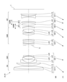
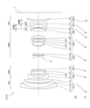
- FIG. 1 is a diagram showing a lens configuration of a variable magnification optical system according to the first embodiment.
- the variable magnification optical system ZL (1) according to the first embodiment has a first lens group G1 having a positive refractive power and a second lens having a negative refractive power arranged in order from the object side along the optical axis.
- Group G2 a third lens group G3 having a positive refractive power, a fourth lens group G4 having a positive refractive power, a fifth lens group G5 having a negative refractive power, and a third lens group having a negative refractive power.
- the aperture stop S is arranged between the second lens group G2 and the third lens group G3. At the time of scaling, the aperture stop S moves along the optical axis together with the third lens group G3.
- the symbol (+) or ( ⁇ ) attached to each lens group symbol indicates the refractive power of each lens group, and this also applies to all the following examples.
- the first lens group G1 is a junction positive lens of a negative meniscus lens L11 having a convex surface facing the object side and a positive meniscus lens L12 having a convex surface facing the object side, which are arranged in order from the object side along the optical axis, and an object. It is composed of a positive meniscus lens L13 with a convex surface facing to the side.
- the second lens group G2 includes a negative meniscus lens L21 having a convex surface facing the object side, a negative meniscus lens L22 having a convex surface facing the object side, and a convex surface facing the object side, arranged in order from the object side along the optical axis. It is composed of a positive meniscus lens L23 bonded to the positive meniscus lens L23 and a negative meniscus lens L24 with a concave surface facing the object side.
- the negative meniscus lens L21 has an aspherical lens surface on the object side.
- the third lens group G3 is composed of a biconvex positive lens L31.
- the positive lens L31 has an aspherical lens surface on the object side.
- the fourth lens group G4 is a junction positive lens of a negative meniscus lens L41 having a convex surface facing the object side and a biconvex positive lens L42 arranged in order from the object side along the optical axis, and a biconvex positive lens. It is composed of a bonded positive lens of the lens L43 and a negative meniscus lens L44 having a concave surface facing the object side, and a positive meniscus lens L45 having a concave surface facing the object side.
- the positive meniscus lens L45 has an aspherical lens surface on the object side.
- the fifth lens group G5 is composed of a positive meniscus lens L51 having a concave surface facing the object side and a negative lens L52 having both concave shapes arranged in order from the object side along the optical axis.
- the sixth lens group G6 is composed of a biconcave negative lens L61.
- the negative lens L61 has an aspherical lens surface on the object side.
- the seventh lens group G7 is composed of a positive meniscus lens L71 with a convex surface facing the object side.
- the image plane I is arranged on the image side of the seventh lens group G7.
- the first lens group G1 constitutes the front lens group GA having a positive refractive power.
- the second lens group G2 constitutes the first intermediate lens group GM1 having a negative refractive power.
- the third lens group G3 and the fourth lens group G4 form a second intermediate lens group GM2 having a positive refractive power as a whole.
- the fifth lens group G5, the sixth lens group G6, and the seventh lens group G7 together form a subsequent lens group GR having a negative refractive power as a whole.
- the fifth lens group G5 and the sixth lens group G6 constituting the succeeding lens group GR are on the image side along the optical axis with different trajectories (movement amount). Move to.
- the fifth lens group G5 corresponds to the first in-focus lens group GF1 arranged on the most object side of the succeeding lens group GR.
- the sixth lens group G6 corresponds to the second in-focus lens group GF2, which is another in-focus lens group arranged on the image side of the first in-focus lens group GF1.
- Table 1 below lists the specifications of the variable magnification optical system according to the first embodiment.
- FIG. 2A is a diagram of various aberrations at infinity focusing in the wide-angle end state of the variable magnification optical system according to the first embodiment.
- FIG. 2B is a diagram of various aberrations at infinity focusing in the telephoto end state of the variable magnification optical system according to the first embodiment.
- FIG. 3A is a diagram of various aberrations at the time of short-distance focusing in the wide-angle end state of the variable magnification optical system according to the first embodiment.
- FIG. 3B is a diagram of various aberrations at the time of short-distance focusing in the telephoto end state of the variable magnification optical system according to the first embodiment.
- FNO indicates an F number and Y indicates an image height.
- NA indicates the numerical aperture and Y indicates the image height.
- the spherical aberration diagram shows the value of the F number or numerical aperture corresponding to the maximum aperture
- the astigmatism diagram and the distortion diagram show the maximum image height
- the coma aberration diagram shows the value of each image height.
- the solid line shows the sagittal image plane and the broken line shows the meridional image plane.
- the same reference numerals as those of the present embodiment are used, and duplicate description is omitted.
- variable magnification optical system satisfactorily corrects various aberrations from the wide-angle end state to the telephoto end state not only at infinity focusing but also at short-distance focusing. It can be seen that it has excellent imaging performance.
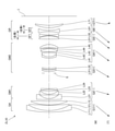
- FIG. 4 is a diagram showing a lens configuration of the variable magnification optical system according to the second embodiment.
- the variable magnification optical system ZL (2) according to the second embodiment has a first lens group G1 having a positive refractive power and a second lens having a negative refractive power arranged in order from the object side along the optical axis.
- Group G2 a third lens group G3 having a positive refractive power, a fourth lens group G4 having a positive refractive power, a fifth lens group G5 having a positive refractive power, and a third lens group having a negative refractive power.
- the aperture stop S is arranged between the second lens group G2 and the third lens group G3. At the time of scaling, the aperture stop S moves along the optical axis together with the third lens group G3.
- the first lens group G1 is a junction positive lens of a negative meniscus lens L11 having a convex surface facing the object side and a positive meniscus lens L12 having a convex surface facing the object side, which are arranged in order from the object side along the optical axis, and an object. It is composed of a positive meniscus lens L13 with a convex surface facing to the side.
- the second lens group G2 is a junction of a negative meniscus lens L21 having a convex surface facing the object side arranged in order from the object side along the optical axis, a biconcave negative lens L22, and a biconvex positive lens L23. It is composed of a positive lens and a negative meniscus lens L24 with a concave surface facing the object side.
- the negative meniscus lens L21 has an aspherical lens surface on the object side.
- the third lens group G3 includes a positive meniscus lens L31 having a convex surface facing the object side, a biconvex positive lens L32, and a negative meniscus having a convex surface facing the object side, arranged in order from the object side along the optical axis. It is composed of a bonded positive lens of a lens L33 and a biconvex positive lens L34, and a negative meniscus lens L35 with a concave surface facing the object side.
- the fourth lens group G4 is composed of a bonded positive lens of a negative meniscus lens L41 with a convex surface facing the object side and a biconvex positive lens L42.
- the fifth lens group G5 is a junction of a biconcave negative lens L51 arranged in order from the object side along the optical axis, a biconvex positive lens L52, and a negative meniscus lens L53 with a concave surface facing the object side. It consists of a positive lens.
- the negative meniscus lens L53 has an aspherical lens surface on the image side.
- the sixth lens group G6 is composed of a biconcave negative lens L61.
- the negative lens L61 has an aspherical lens surface on the object side.
- the seventh lens group G7 is composed of a biconvex positive lens L71.
- the image plane I is arranged on the image side of the seventh lens group G7.
- the first lens group G1 constitutes the front lens group GA having a positive refractive power.
- the second lens group G2 constitutes the first intermediate lens group GM1 having a negative refractive power.
- the third lens group G3 and the fourth lens group G4 form a second intermediate lens group GM2 having a positive refractive power as a whole.
- the fifth lens group G5, the sixth lens group G6, and the seventh lens group G7 together form a subsequent lens group GR having a negative refractive power as a whole.
- the fifth lens group G5 corresponds to the first in-focus lens group GF1 arranged on the most object side of the succeeding lens group GR.
- the sixth lens group G6 corresponds to the second in-focus lens group GF2, which is another in-focus lens group arranged on the image side of the first in-focus lens group GF1.
- Table 2 below lists the specifications of the variable magnification optical system according to the second embodiment.
- FIG. 5A is a diagram of various aberrations at infinity focusing in the wide-angle end state of the variable magnification optical system according to the second embodiment.
- FIG. 5B is an aberration diagram at infinity focusing in the telephoto end state of the variable magnification optical system according to the second embodiment.
- FIG. 6A is a diagram of various aberrations at the time of short-distance focusing in the wide-angle end state of the variable magnification optical system according to the second embodiment.
- FIG. 6B is a diagram of various aberrations at the time of short-distance focusing in the telephoto end state of the variable magnification optical system according to the second embodiment.
- variable magnification optical system According to the second embodiment satisfactorily corrects various aberrations from the wide-angle end state to the telephoto end state not only at infinity focusing but also at short-distance focusing. It can be seen that it has excellent imaging performance.
- FIG. 7 is a diagram showing a lens configuration of the variable magnification optical system according to the third embodiment.
- the variable magnification optical system ZL (3) according to the third embodiment has a first lens group G1 having a positive refractive power and a second lens having a negative refractive power arranged in order from the object side along the optical axis.
- Group G2 a third lens group G3 having a positive refractive power, a fourth lens group G4 having a positive refractive power, a fifth lens group G5 having a positive refractive power, and a third lens group having a positive refractive power.
- the aperture stop S is arranged between the second lens group G2 and the third lens group G3. At the time of scaling, the aperture stop S moves along the optical axis together with the third lens group G3.
- the first lens group G1 is a junction positive lens of a plano-concave negative lens L11 and a biconvex positive lens L12 arranged in order from the object side along the optical axis and facing the object side, and the object side. It is composed of a positive meniscus lens L13 having a convex surface facing the surface.
- the second lens group G2 is a junction of a negative meniscus lens L21 having a convex surface facing the object side arranged in order from the object side along the optical axis, a biconcave negative lens L22, and a biconvex positive lens L23. It is composed of a positive lens and a flat concave negative lens L24 with a plane facing the image side.
- the negative meniscus lens L21 has an aspherical lens surface on the object side.
- the third lens group G3 includes a positive meniscus lens L31 having a convex surface facing the object side, a biconvex positive lens L32, and a negative meniscus having a concave surface facing the object side, arranged in order from the object side along the optical axis. It is composed of a lens L33.
- the positive meniscus lens L31 has an aspherical lens surface on the object side.
- the fourth lens group G4 is a junction of a biconvex positive lens L41 arranged in order from the object side along the optical axis, a negative meniscus lens L42 with a convex surface facing the object side, and a biconvex positive lens L43. It consists of a positive lens.
- the fifth lens group G5 is composed of a negative meniscus lens L51 having a concave surface facing the object side and a biconvex positive lens L52 arranged in order from the object side along the optical axis.
- the sixth lens group G6 is composed of a positive meniscus lens L61 with a concave surface facing the object side.
- the positive meniscus lens L61 has an aspherical lens surface on the image side.
- the seventh lens group G7 is composed of a biconcave negative lens L71 arranged in order from the object side along the optical axis, and a positive meniscus lens L72 with a convex surface facing the object side.
- the image plane I is arranged on the image side of the seventh lens group G7.
- the first lens group G1 constitutes the front lens group GA having a positive refractive power.
- the second lens group G2 constitutes the first intermediate lens group GM1 having a negative refractive power.
- the third lens group G3 and the fourth lens group G4 form a second intermediate lens group GM2 having a positive refractive power as a whole.
- the fifth lens group G5, the sixth lens group G6, and the seventh lens group G7 together form a subsequent lens group GR having a negative refractive power as a whole.
- the fifth lens group G5 and the sixth lens group G6 constituting the succeeding lens group GR have different trajectories (movement amounts) from each other on the object side along the optical axis.
- the fifth lens group G5 corresponds to the first in-focus lens group GF1 arranged on the most object side of the succeeding lens group GR.
- the sixth lens group G6 corresponds to the second in-focus lens group GF2, which is another in-focus lens group arranged on the image side of the first in-focus lens group GF1.
- Table 3 lists the specifications of the variable magnification optical system according to the third embodiment.
- FIG. 8A is an aberration diagram at infinity focusing in the wide-angle end state of the variable magnification optical system according to the third embodiment.
- FIG. 8B is an aberration diagram at infinity focusing in the telephoto end state of the variable magnification optical system according to the third embodiment.
- FIG. 9A is a diagram of various aberrations at the time of short-distance focusing in the wide-angle end state of the variable magnification optical system according to the third embodiment.
- FIG. 9B is a diagram of various aberrations at the time of short-distance focusing in the telephoto end state of the variable magnification optical system according to the third embodiment.
- variable magnification optical system According to the third embodiment satisfactorily corrects various aberrations from the wide-angle end state to the telephoto end state not only at infinity focusing but also at short-distance focusing. It can be seen that it has excellent imaging performance.
- FIG. 10 is a diagram showing a lens configuration of the variable magnification optical system according to the fourth embodiment.
- the variable magnification optical system ZL (4) according to the fourth embodiment has a first lens group G1 having a positive refractive power and a second lens having a negative refractive power arranged in order from the object side along the optical axis.
- Group G2 a third lens group G3 having a positive refractive power, a fourth lens group G4 having a positive refractive power, a fifth lens group G5 having a negative refractive power, and a third lens group having a negative refractive power.
- the aperture stop S is arranged between the second lens group G2 and the third lens group G3. At the time of scaling, the aperture stop S moves along the optical axis together with the third lens group G3.
- the first lens group G1 is a junction positive lens of a negative meniscus lens L11 having a convex surface facing the object side and a positive meniscus lens L12 having a convex surface facing the object side, which are arranged in order from the object side along the optical axis, and an object. It is composed of a positive meniscus lens L13 with a convex surface facing to the side.
- the second lens group G2 includes a negative meniscus lens L21 having a convex surface facing the object side, a negative meniscus lens L22 having a convex surface facing the object side, and a convex surface facing the object side, arranged in order from the object side along the optical axis. It is composed of a bonded positive lens with a positive meniscus lens L23 and a negative lens L24 having a biconcave shape.
- the negative meniscus lens L21 has an aspherical lens surface on the object side.
- the third lens group G3 is composed of a positive meniscus lens L31 having a convex surface facing the object side and a regular meniscus lens L32 having a convex surface facing the object side.
- the positive meniscus lens L31 has an aspherical lens surface on the object side.
- the fourth lens group G4 is a junction positive lens of a negative meniscus lens L41 having a convex surface facing the object side and a biconvex positive lens L42 arranged in order from the object side along the optical axis, and a biconvex positive lens. It is composed of a junction negative lens of the lens L43 and a negative meniscus lens L44 having a concave surface facing the object side, and a positive meniscus lens L45 having a concave surface facing the object side.
- the positive meniscus lens L45 has an aspherical lens surface on the object side.
- the fifth lens group G5 is composed of a biconvex positive lens L51 and a biconcave negative lens L52 arranged in order from the object side along the optical axis.
- the sixth lens group G6 is composed of a biconcave negative lens L61.
- the negative lens L61 has an aspherical lens surface on the object side.
- the seventh lens group G7 is composed of a positive meniscus lens L71 with a convex surface facing the object side.
- the image plane I is arranged on the image side of the seventh lens group G7.
- the first lens group G1 constitutes the front lens group GA having a positive refractive power.
- the second lens group G2 constitutes the first intermediate lens group GM1 having a negative refractive power.
- the third lens group G3 and the fourth lens group G4 form a second intermediate lens group GM2 having a positive refractive power as a whole.
- the fifth lens group G5, the sixth lens group G6, and the seventh lens group G7 together form a subsequent lens group GR having a negative refractive power as a whole.
- the fifth lens group G5 and the sixth lens group G6 constituting the succeeding lens group GR are on the image side along the optical axis with different trajectories (movement amount). Move to.
- the fifth lens group G5 corresponds to the first in-focus lens group GF1 arranged on the most object side of the succeeding lens group GR.
- the sixth lens group G6 corresponds to the second in-focus lens group GF2, which is another in-focus lens group arranged on the image side of the first in-focus lens group GF1.
- Table 4 lists the specifications of the variable magnification optical system according to the fourth embodiment.
- FIG. 11A is a diagram of various aberrations at infinity focusing in the wide-angle end state of the variable magnification optical system according to the fourth embodiment.
- FIG. 11B is an aberration diagram at infinity focusing in the telephoto end state of the variable magnification optical system according to the fourth embodiment.
- FIG. 12A is a diagram of various aberrations at the time of short-distance focusing in the wide-angle end state of the variable magnification optical system according to the fourth embodiment.
- FIG. 12B is a diagram of various aberrations at the time of short-distance focusing in the telephoto end state of the variable magnification optical system according to the fourth embodiment.
- variable magnification optical system satisfactorily corrects various aberrations from the wide-angle end state to the telephoto end state not only at infinity focusing but also at short-distance focusing. It can be seen that it has excellent imaging performance.
- FIG. 13 is a diagram showing a lens configuration of the variable magnification optical system according to the fifth embodiment.
- the variable magnification optical system ZL (5) according to the fifth embodiment has a first lens group G1 having a positive refractive power and a second lens having a negative refractive power arranged in order from the object side along the optical axis.
- Group G2 a third lens group G3 having a negative refractive power, a fourth lens group G4 having a positive refractive power, a fifth lens group G5 having a positive refractive power, and a third lens group having a negative refractive power.
- the aperture stop S is arranged between the third lens group G3 and the fourth lens group G4. At the time of scaling, the aperture stop S moves along the optical axis together with the fourth lens group G4.
- the first lens group G1 is a junction positive lens of a negative meniscus lens L11 having a convex surface facing the object side and a positive meniscus lens L12 having a convex surface facing the object side, which are arranged in order from the object side along the optical axis, and an object. It is composed of a positive meniscus lens L13 with a convex surface facing to the side.
- the second lens group G2 includes a biconcave negative lens L21 arranged in order from the object side along the optical axis, a negative meniscus lens L22 having a convex surface facing the object side, and a positive meniscus lens L22 having a convex surface facing the object side. It is composed of a positive junction lens with L23 and a positive lens.
- the negative lens L21 has an aspherical lens surface on the object side.
- the third lens group G3 is composed of a biconcave negative lens L31.
- the fourth lens group G4 is composed of a positive meniscus lens L41 having a convex surface facing the object side and a regular meniscus lens L42 having a convex surface facing the object side, which are arranged in order from the object side along the optical axis.
- the positive meniscus lens L41 has an aspherical lens surface on the object side.
- the fifth lens group G5 has a positive meniscus lens L51 having a convex surface facing the object side and a positive lens L52 having a biconvex shape arranged in order from the object side along the optical axis, and a concave surface on the object side. It is composed of a junction negative lens of a positive meniscus lens L53 facing and a negative meniscus lens L54 having a concave surface facing the object side, and a positive meniscus lens L55 having a concave surface facing the object side.
- the positive meniscus lens L55 has an aspherical lens surface on the object side.
- the sixth lens group G6 is composed of a biconvex positive lens L61 and a biconcave negative lens L62 arranged in order from the object side along the optical axis.
- the 7th lens group G7 is composed of a biconcave negative lens L71.
- the negative lens L71 has an aspherical lens surface on the object side.
- the eighth lens group G8 is composed of a positive meniscus lens L81 with a convex surface facing the object side.
- the image plane I is arranged on the image side of the eighth lens group G8.
- the first lens group G1 constitutes the front lens group GA having a positive refractive power.
- the second lens group G2 and the third lens group G3 form a first intermediate lens group GM1 having a negative refractive power as a whole.
- the fourth lens group G4 and the fifth lens group G5 constitute a second intermediate lens group GM2 having a positive refractive power as a whole.
- the sixth lens group G6, the seventh lens group G7, and the eighth lens group G8 together form a subsequent lens group GR having a negative refractive power as a whole.
- the 6th lens group G6 and the 7th lens group G7 constituting the succeeding lens group GR are on the image side along the optical axis with different trajectories (movement amount). Move to. That is, the sixth lens group G6 corresponds to the first in-focus lens group GF1 arranged on the most object side of the succeeding lens group GR.
- the seventh lens group G7 corresponds to the second in-focus lens group GF2, which is another in-focus lens group arranged on the image side of the first in-focus lens group GF1.
- FIG. 14A is a diagram of various aberrations at infinity focusing in the wide-angle end state of the variable magnification optical system according to the fifth embodiment.
- FIG. 14B is an aberration diagram at infinity focusing in the telephoto end state of the variable magnification optical system according to the fifth embodiment.
- FIG. 15A is a diagram of various aberrations at the time of short-distance focusing in the wide-angle end state of the variable magnification optical system according to the fifth embodiment.
- FIG. 15B is a diagram of various aberrations at the time of short-distance focusing in the telephoto end state of the variable magnification optical system according to the fifth embodiment.
- variable magnification optical system satisfactorily corrects various aberrations from the wide-angle end state to the telephoto end state not only at infinity focusing but also at short-distance focusing. It can be seen that it has excellent imaging performance.
- FIG. 16 is a diagram showing a lens configuration of the variable magnification optical system according to the sixth embodiment.
- the first lens group G1 having a positive refractive power and the second lens having a negative refractive power arranged in order from the object side along the optical axis.
- Group G2 a third lens group G3 having a positive refractive power, a fourth lens group G4 having a positive refractive power, a fifth lens group G5 having a negative refractive power, and a third lens group having a positive refractive power.
- the aperture stop S is arranged between the second lens group G2 and the third lens group G3. At the time of scaling, the aperture stop S moves along the optical axis together with the third lens group G3.
- the first lens group G1 includes a bonded positive lens of a negative meniscus lens L11 having a convex surface facing the object side and a biconvex positive lens L12 arranged in order from the object side along the optical axis, and a convex surface toward the object side. It is composed of a positive meniscus lens L13 directed to the lens.
- the second lens group G2 is a junction of a negative meniscus lens L21 having a convex surface facing the object side arranged in order from the object side along the optical axis, a biconcave negative lens L22, and a biconvex positive lens L23. It is composed of a positive lens and a biconcave negative lens L24.
- the negative meniscus lens L21 has an aspherical lens surface on the object side.
- the third lens group G3 includes a positive meniscus lens L31 having a convex surface facing the object side, a biconvex positive lens L32, and a negative meniscus having a concave surface facing the object side, arranged in order from the object side along the optical axis. It is composed of a lens L33.
- the positive meniscus lens L31 has an aspherical lens surface on the object side.
- the fourth lens group G4 is a junction of a biconvex positive lens L41 arranged in order from the object side along the optical axis, a negative meniscus lens L42 with a convex surface facing the object side, and a biconvex positive lens L43. It consists of a negative lens.
- the fifth lens group G5 is composed of a negative meniscus lens L51 with a concave surface facing the object side.
- the sixth lens group G6 is composed of a biconvex positive lens L61.
- the seventh lens group G7 is composed of a positive meniscus lens L71 with a concave surface facing the object side.
- the positive meniscus lens L71 has an aspherical lens surface on the image side.
- the eighth lens group G8 is composed of a biconcave negative lens L81 arranged in order from the object side along the optical axis, and a positive meniscus lens L82 with a convex surface facing the object side.
- the image plane I is arranged on the image side of the eighth lens group G8.
- the first lens group G1 constitutes the front lens group GA having a positive refractive power.
- the second lens group G2 constitutes the first intermediate lens group GM1 having a negative refractive power.
- the third lens group G3 and the fourth lens group G4 form a second intermediate lens group GM2 having a positive refractive power as a whole.
- the fifth lens group G5, the sixth lens group G6, the seventh lens group G7, and the eighth lens group G8 together form a subsequent lens group GR having a negative refractive power as a whole.
- the fifth lens group G5, the sixth lens group G6, and the seventh lens group G7 constituting the succeeding lens group GR emit light with different trajectories (movement amount).
- the fifth lens group G5 corresponds to the first in-focus lens group GF1 arranged on the most object side of the succeeding lens group GR.
- the sixth lens group G6 corresponds to the second in-focus lens group GF2, which is another in-focus lens group arranged on the image side of the first in-focus lens group GF1.
- the seventh lens group G7 corresponds to the third in-focus lens group GF3, which is another in-focus lens group arranged on the image side of the first in-focus lens group GF1.
- Table 6 below lists the specifications of the variable magnification optical system according to the sixth embodiment.
- FIG. 17A is a diagram of various aberrations at infinity focusing in the wide-angle end state of the variable magnification optical system according to the sixth embodiment.
- FIG. 17B is an aberration diagram at infinity focusing in the telephoto end state of the variable magnification optical system according to the sixth embodiment.
- FIG. 18A is a diagram of various aberrations at the time of short-distance focusing in the wide-angle end state of the variable magnification optical system according to the sixth embodiment.
- FIG. 18B is a diagram of various aberrations at the time of short-distance focusing in the telephoto end state of the variable magnification optical system according to the sixth embodiment.
- variable magnification optical system According to the sixth embodiment satisfactorily corrects various aberrations from the wide-angle end state to the telephoto end state not only at infinity focusing but also at short-distance focusing. It can be seen that it has excellent imaging performance.
- FIG. 19 is a diagram showing a lens configuration of the variable magnification optical system according to the seventh embodiment.
- the variable magnification optical system ZL (7) according to the seventh embodiment has a first lens group G1 having a positive refractive power and a second lens having a negative refractive power arranged in order from the object side along the optical axis.
- Group G2 a third lens group G3 having a positive refractive power, a fourth lens group G4 having a negative refractive power, a fifth lens group G5 having a positive refractive power, and a third lens group having a positive refractive power.
- the aperture stop S is arranged between the second lens group G2 and the third lens group G3. At the time of scaling, the aperture stop S moves along the optical axis together with the third lens group G3.
- the first lens group G1 includes a bonded positive lens of a negative meniscus lens L11 having a convex surface facing the object side and a biconvex positive lens L12 arranged in order from the object side along the optical axis, and a convex surface toward the object side. It is composed of a positive meniscus lens L13 directed to the lens.
- the second lens group G2 is a junction of a negative meniscus lens L21 having a convex surface facing the object side arranged in order from the object side along the optical axis, a biconcave negative lens L22, and a biconvex positive lens L23. It is composed of a positive lens and a flat concave negative lens L24 with a plane facing the image side.
- the negative meniscus lens L21 has an aspherical lens surface on the object side.
- the third lens group G3 is composed of a biconvex positive lens L31 and a biconvex positive lens L32 arranged in order from the object side along the optical axis.
- the positive lens L31 has an aspherical lens surface on the object side.
- the fourth lens group G4 is composed of a negative lens L41 having a concave shape.
- the fifth lens group G5 is a junction of a biconvex positive lens L51 arranged in order from the object side along the optical axis, a negative meniscus lens L52 having a convex surface facing the object side, and a biconvex positive lens L53. It consists of a positive lens.
- the sixth lens group G6 is composed of a negative meniscus lens L61 having a concave surface facing the object side and a biconvex positive lens L62 arranged in order from the object side along the optical axis.
- the seventh lens group G7 is composed of a positive meniscus lens L71 with a concave surface facing the object side.
- the positive meniscus lens L71 has an aspherical lens surface on the image side.
- the eighth lens group G8 is composed of a biconcave negative lens L81 arranged in order from the object side along the optical axis, and a positive meniscus lens L82 with a convex surface facing the object side.
- the image plane I is arranged on the image side of the eighth lens group G8.
- the first lens group G1 constitutes the front lens group GA having a positive refractive power.
- the second lens group G2 constitutes the first intermediate lens group GM1 having a negative refractive power.
- the third lens group G3, the fourth lens group G4, and the fifth lens group G5 together form a second intermediate lens group GM2 having a positive refractive power as a whole.
- the sixth lens group G6, the seventh lens group G7, and the eighth lens group G8 together form a subsequent lens group GR having a negative refractive power as a whole.
- the 6th lens group G6 and the 7th lens group G7 constituting the succeeding lens group GR are on the object side along the optical axis with different trajectories (movement amount). Move to. That is, the sixth lens group G6 corresponds to the first in-focus lens group GF1 arranged on the most object side of the succeeding lens group GR.
- the seventh lens group G7 corresponds to the second in-focus lens group GF2, which is another in-focus lens group arranged on the image side of the first in-focus lens group GF1.
- Table 7 below lists the specifications of the variable magnification optical system according to the seventh embodiment.
- FIG. 20A is a diagram of various aberrations at infinity focusing in the wide-angle end state of the variable magnification optical system according to the seventh embodiment.
- FIG. 20B is an aberration diagram at infinity focusing in the telephoto end state of the variable magnification optical system according to the seventh embodiment.
- FIG. 21 (A) is a diagram of various aberrations at the time of short-distance focusing in the wide-angle end state of the variable magnification optical system according to the seventh embodiment.
- FIG. 21B is a diagram of various aberrations at the time of short-distance focusing in the telephoto end state of the variable magnification optical system according to the seventh embodiment.
- variable magnification optical system according to the seventh embodiment satisfactorily corrects various aberrations from the wide-angle end state to the telephoto end state not only at infinity focusing but also at short-distance focusing. It can be seen that it has excellent imaging performance.
- Conditional expression (1) -0.37 ⁇ fFs / fFy ⁇ 0.37
- Conditional expression (2) 2.00 ⁇ f1 / fw ⁇ 8.00
- Conditional expression (3) -6.00 ⁇ fFs / fw ⁇ 6.00
- Conditional expression (4) 4.30 ⁇ f1 / (-fM1w) ⁇ 10.00
- Conditional expression (5) 1.50 ⁇ f1 / fM21 ⁇ 7.00
- Conditional expression (8) 1.50 ⁇
- Conditional expression (9) 0.90 ⁇
- Conditional expression (9) 0.90 ⁇
- Conditional expression (9) 0.
- the focusing lens group by reducing the size and weight of the focusing lens group, it is possible to realize quiet and high-speed focusing (focusing) without increasing the size of the lens barrel. Further, it is possible to realize a variable magnification optical system in which the aberration fluctuation at the time of scaling from the wide-angle end state to the telephoto end state and the aberration fluctuation at the time of focusing from an infinity object to a short-range object are small.
- variable magnification optical system of the present embodiment a 7-group configuration and an 8-group configuration are shown, but the present application is not limited to this, and a variable magnification optical system having another group configuration (for example, 9 groups, etc.) is used. It can also be configured. Specifically, a lens or a lens group may be added to the most object side or the most image plane side of the variable magnification optical system of the present embodiment.
- the lens group refers to a portion having at least one lens separated by an air interval that changes at the time of scaling.
- a single lens group, a plurality of lens groups, or a partial lens group may be moved in the optical axis direction to focus on a short-range object from an infinity object.
- the in-focus lens group can also be applied to autofocus, and is also suitable for driving a motor for autofocus (using an ultrasonic motor or the like).
- the lens group or partial lens group is moved so as to have a component in the direction perpendicular to the optical axis, or is rotationally moved (swinged) in the in-plane direction including the optical axis to correct image blur caused by camera shake. It may be used as an anti-vibration lens group.
- the lens surface may be formed of a spherical surface or a flat surface, or may be formed of an aspherical surface.
- lens processing and assembly adjustment are facilitated, and deterioration of optical performance due to processing and assembly adjustment errors can be prevented, which is preferable. Further, even if the image plane is displaced, the deterioration of the depiction performance is small, which is preferable.
- the aspherical surface is an aspherical surface formed by grinding, a glass mold aspherical surface formed by forming glass into an aspherical surface shape, or a composite aspherical surface formed by forming resin on the glass surface into an aspherical surface shape. It doesn't matter which one. Further, the lens surface may be a diffraction surface, and the lens may be a refractive index distribution type lens (GRIN lens) or a plastic lens.
- GRIN lens refractive index distribution type lens
- the aperture diaphragm is preferably arranged between the second lens group and the third lens group, or between the third lens group and the fourth lens group, but the lens is not provided with a member as the aperture diaphragm.
- the role may be substituted by the frame of.
- Each lens surface may be provided with an antireflection film having high transmittance in a wide wavelength range in order to reduce flare and ghost and achieve high contrast optical performance.
- G1 1st lens group G2 2nd lens group G3 3rd lens group G4 4th lens group G5 5th lens group G6 6th lens group G7 7th lens group G8 8th lens group I image plane S Aperture aperture
Landscapes
- Physics & Mathematics (AREA)
- General Physics & Mathematics (AREA)
- Optics & Photonics (AREA)
- Nonlinear Science (AREA)
- Lenses (AREA)
Priority Applications (4)
| Application Number | Priority Date | Filing Date | Title |
|---|---|---|---|
| US18/018,036 US20230273415A1 (en) | 2020-07-28 | 2021-06-25 | Zoom optical system, optical apparatus and method for manufacturing the zoom optical system |
| CN202180047082.3A CN115867845B (zh) | 2020-07-28 | 2021-06-25 | 变倍光学系统以及光学设备 |
| JP2022540080A JP7364084B2 (ja) | 2020-07-28 | 2021-06-25 | 変倍光学系および光学機器 |
| JP2023172446A JP2023171918A (ja) | 2020-07-28 | 2023-10-04 | 変倍光学系、光学機器、および変倍光学系の製造方法 |
Applications Claiming Priority (2)
| Application Number | Priority Date | Filing Date | Title |
|---|---|---|---|
| JP2020-126910 | 2020-07-28 | ||
| JP2020126910 | 2020-07-28 |
Publications (1)
| Publication Number | Publication Date |
|---|---|
| WO2022024622A1 true WO2022024622A1 (ja) | 2022-02-03 |
Family
ID=80035526
Family Applications (1)
| Application Number | Title | Priority Date | Filing Date |
|---|---|---|---|
| PCT/JP2021/024061 Ceased WO2022024622A1 (ja) | 2020-07-28 | 2021-06-25 | 変倍光学系、光学機器、および変倍光学系の製造方法 |
Country Status (4)
| Country | Link |
|---|---|
| US (1) | US20230273415A1 (https=) |
| JP (2) | JP7364084B2 (https=) |
| CN (1) | CN115867845B (https=) |
| WO (1) | WO2022024622A1 (https=) |
Citations (7)
| Publication number | Priority date | Publication date | Assignee | Title |
|---|---|---|---|---|
| WO2015146067A1 (ja) * | 2014-03-28 | 2015-10-01 | パナソニックIpマネジメント株式会社 | ズームレンズ系、交換レンズ装置、及びカメラシステム |
| JP2015215438A (ja) * | 2014-05-09 | 2015-12-03 | キヤノン株式会社 | ズームレンズ及びそれを有する撮像装置 |
| JP2019184632A (ja) * | 2018-04-02 | 2019-10-24 | キヤノン株式会社 | ズームレンズ及びそれを有する撮像装置 |
| JP2020052338A (ja) * | 2018-09-28 | 2020-04-02 | 株式会社タムロン | ズームレンズ及び撮像装置 |
| JP2020064175A (ja) * | 2018-10-17 | 2020-04-23 | キヤノン株式会社 | ズームレンズ及びそれを有する撮像装置 |
| JP2020086324A (ja) * | 2018-11-30 | 2020-06-04 | 株式会社タムロン | ズームレンズ及び撮像装置 |
| JP2020106627A (ja) * | 2018-12-27 | 2020-07-09 | キヤノン株式会社 | 光学系及びそれを有する撮像装置 |
Family Cites Families (8)
| Publication number | Priority date | Publication date | Assignee | Title |
|---|---|---|---|---|
| JP4931121B2 (ja) * | 2006-09-28 | 2012-05-16 | オリンパスイメージング株式会社 | 光路を反射する反射面を備えたズームレンズ及びそれを備えた撮像装置 |
| KR101706266B1 (ko) * | 2009-12-24 | 2017-02-27 | 삼성전자주식회사 | 줌 렌즈 및 이를 구비한 촬영 장치 |
| JP2014066945A (ja) * | 2012-09-27 | 2014-04-17 | Sony Corp | ズームレンズおよび撮像装置 |
| WO2015146175A1 (ja) * | 2014-03-27 | 2015-10-01 | 株式会社ニコン | ズームレンズ、撮像装置及びズームレンズの製造方法 |
| US9835932B2 (en) * | 2015-01-21 | 2017-12-05 | Panasonic Intellectual Property Management Co., Ltd. | Zoom lens system, interchangeable lens device, and camera system |
| US12529873B2 (en) * | 2018-11-20 | 2026-01-20 | Nikon Corporation | Zoom optical system, optical device, and method for manufacturing zoom optical system |
| JP7150625B2 (ja) * | 2019-01-23 | 2022-10-11 | キヤノン株式会社 | ズームレンズ、撮像装置、レンズ装置 |
| JP7277288B2 (ja) * | 2019-07-02 | 2023-05-18 | キヤノン株式会社 | ズームレンズ及びそれを有する撮像装置 |
-
2021
- 2021-06-25 US US18/018,036 patent/US20230273415A1/en active Pending
- 2021-06-25 JP JP2022540080A patent/JP7364084B2/ja active Active
- 2021-06-25 CN CN202180047082.3A patent/CN115867845B/zh active Active
- 2021-06-25 WO PCT/JP2021/024061 patent/WO2022024622A1/ja not_active Ceased
-
2023
- 2023-10-04 JP JP2023172446A patent/JP2023171918A/ja active Pending
Patent Citations (7)
| Publication number | Priority date | Publication date | Assignee | Title |
|---|---|---|---|---|
| WO2015146067A1 (ja) * | 2014-03-28 | 2015-10-01 | パナソニックIpマネジメント株式会社 | ズームレンズ系、交換レンズ装置、及びカメラシステム |
| JP2015215438A (ja) * | 2014-05-09 | 2015-12-03 | キヤノン株式会社 | ズームレンズ及びそれを有する撮像装置 |
| JP2019184632A (ja) * | 2018-04-02 | 2019-10-24 | キヤノン株式会社 | ズームレンズ及びそれを有する撮像装置 |
| JP2020052338A (ja) * | 2018-09-28 | 2020-04-02 | 株式会社タムロン | ズームレンズ及び撮像装置 |
| JP2020064175A (ja) * | 2018-10-17 | 2020-04-23 | キヤノン株式会社 | ズームレンズ及びそれを有する撮像装置 |
| JP2020086324A (ja) * | 2018-11-30 | 2020-06-04 | 株式会社タムロン | ズームレンズ及び撮像装置 |
| JP2020106627A (ja) * | 2018-12-27 | 2020-07-09 | キヤノン株式会社 | 光学系及びそれを有する撮像装置 |
Also Published As
| Publication number | Publication date |
|---|---|
| JPWO2022024622A1 (https=) | 2022-02-03 |
| CN115867845B (zh) | 2026-04-17 |
| CN115867845A (zh) | 2023-03-28 |
| JP7364084B2 (ja) | 2023-10-18 |
| JP2023171918A (ja) | 2023-12-05 |
| US20230273415A1 (en) | 2023-08-31 |
Similar Documents
| Publication | Publication Date | Title |
|---|---|---|
| JP7435622B2 (ja) | 変倍光学系および光学機器 | |
| CN110520777A (zh) | 变倍光学系统、光学装置和制造变倍光学系统的方法 | |
| JP7438795B2 (ja) | ズームレンズおよび撮像装置 | |
| JP2010191199A (ja) | ズームレンズ、光学機器及びズームレンズの製造方法 | |
| JP5622103B2 (ja) | ズームレンズ、このズームレンズを搭載した光学機器、及び、ズームレンズの製造方法 | |
| CN113366362A (zh) | 变倍光学系统、光学设备以及变倍光学系统的制造方法 | |
| JP6237147B2 (ja) | 変倍光学系、光学機器及び変倍光学系の製造方法 | |
| JP2026010130A (ja) | 変倍光学系および光学機器 | |
| CN113302533B (zh) | 变倍光学系统以及光学设备 | |
| WO2024053269A1 (ja) | 変倍光学系、光学機器、および変倍光学系の製造方法 | |
| CN110494786A (zh) | 变倍光学系统、光学装置和制造变倍光学系统的方法 | |
| JP6237146B2 (ja) | 変倍光学系、光学機器及び変倍光学系の製造方法 | |
| WO2022137820A1 (ja) | 変倍光学系、光学機器、および変倍光学系の製造方法 | |
| JP7655373B2 (ja) | 変倍光学系および光学機器 | |
| JP7552701B2 (ja) | 変倍光学系および光学機器 | |
| JP6281200B2 (ja) | 変倍光学系及び光学装置 | |
| WO2013111539A1 (ja) | ズームレンズ、光学機器及びズームレンズの製造方法 | |
| JP7364084B2 (ja) | 変倍光学系および光学機器 | |
| JP7409511B2 (ja) | 変倍光学系および光学機器 | |
| WO2021256065A1 (ja) | 光学系、光学機器、および光学系の製造方法 | |
| WO2022009588A1 (ja) | 光学系、光学機器、および光学系の製造方法 | |
| JP7732218B2 (ja) | 変倍光学系、および光学機器 | |
| JPWO2020136744A1 (ja) | 変倍光学系、光学機器および変倍光学系の製造方法 | |
| JPWO2020136743A1 (ja) | 変倍光学系、光学機器および変倍光学系の製造方法 | |
| JP2024011103A (ja) | 変倍光学系、光学機器、および変倍光学系の製造方法 |
Legal Events
| Date | Code | Title | Description |
|---|---|---|---|
| 121 | Ep: the epo has been informed by wipo that ep was designated in this application |
Ref document number: 21850237 Country of ref document: EP Kind code of ref document: A1 |
|
| ENP | Entry into the national phase |
Ref document number: 2022540080 Country of ref document: JP Kind code of ref document: A |
|
| NENP | Non-entry into the national phase |
Ref country code: DE |
|
| 122 | Ep: pct application non-entry in european phase |
Ref document number: 21850237 Country of ref document: EP Kind code of ref document: A1 |