WO2024053269A1 - 変倍光学系、光学機器、および変倍光学系の製造方法 - Google Patents
変倍光学系、光学機器、および変倍光学系の製造方法 Download PDFInfo
- Publication number
- WO2024053269A1 WO2024053269A1 PCT/JP2023/026980 JP2023026980W WO2024053269A1 WO 2024053269 A1 WO2024053269 A1 WO 2024053269A1 JP 2023026980 W JP2023026980 W JP 2023026980W WO 2024053269 A1 WO2024053269 A1 WO 2024053269A1
- Authority
- WO
- WIPO (PCT)
- Prior art keywords
- lens group
- optical system
- lens
- end state
- conditional expression
- Prior art date
Links
- 230000003287 optical effect Effects 0.000 title claims abstract description 323
- 238000004519 manufacturing process Methods 0.000 title claims description 9
- 238000000034 method Methods 0.000 title claims description 9
- 230000014509 gene expression Effects 0.000 claims abstract description 152
- 230000007423 decrease Effects 0.000 claims description 13
- 230000004075 alteration Effects 0.000 description 92
- 238000010586 diagram Methods 0.000 description 44
- 206010010071 Coma Diseases 0.000 description 27
- 230000000694 effects Effects 0.000 description 26
- 239000011347 resin Substances 0.000 description 13
- 229920005989 resin Polymers 0.000 description 13
- 230000005499 meniscus Effects 0.000 description 12
- 102220010919 rs397507454 Human genes 0.000 description 8
- 238000006073 displacement reaction Methods 0.000 description 7
- 238000003384 imaging method Methods 0.000 description 7
- 102220049405 rs147669920 Human genes 0.000 description 7
- 239000011521 glass Substances 0.000 description 6
- 239000002131 composite material Substances 0.000 description 4
- 230000006866 deterioration Effects 0.000 description 2
- 230000006870 function Effects 0.000 description 2
- 230000005484 gravity Effects 0.000 description 2
- 239000004973 liquid crystal related substance Substances 0.000 description 2
- 238000000465 moulding Methods 0.000 description 2
- 101000585359 Homo sapiens Suppressor of tumorigenicity 20 protein Proteins 0.000 description 1
- 102100029860 Suppressor of tumorigenicity 20 protein Human genes 0.000 description 1
- 201000009310 astigmatism Diseases 0.000 description 1
- 239000000463 material Substances 0.000 description 1
- 230000011514 reflex Effects 0.000 description 1
- 230000004044 response Effects 0.000 description 1
- 238000002834 transmittance Methods 0.000 description 1
Images


Classifications
-
- G—PHYSICS
- G02—OPTICS
- G02B—OPTICAL ELEMENTS, SYSTEMS OR APPARATUS
- G02B13/00—Optical objectives specially designed for the purposes specified below
- G02B13/18—Optical objectives specially designed for the purposes specified below with lenses having one or more non-spherical faces, e.g. for reducing geometrical aberration
-
- G—PHYSICS
- G02—OPTICS
- G02B—OPTICAL ELEMENTS, SYSTEMS OR APPARATUS
- G02B15/00—Optical objectives with means for varying the magnification
- G02B15/14—Optical objectives with means for varying the magnification by axial movement of one or more lenses or groups of lenses relative to the image plane for continuously varying the equivalent focal length of the objective
- G02B15/16—Optical objectives with means for varying the magnification by axial movement of one or more lenses or groups of lenses relative to the image plane for continuously varying the equivalent focal length of the objective with interdependent non-linearly related movements between one lens or lens group, and another lens or lens group
- G02B15/163—Optical objectives with means for varying the magnification by axial movement of one or more lenses or groups of lenses relative to the image plane for continuously varying the equivalent focal length of the objective with interdependent non-linearly related movements between one lens or lens group, and another lens or lens group having a first movable lens or lens group and a second movable lens or lens group, both in front of a fixed lens or lens group
- G02B15/167—Optical objectives with means for varying the magnification by axial movement of one or more lenses or groups of lenses relative to the image plane for continuously varying the equivalent focal length of the objective with interdependent non-linearly related movements between one lens or lens group, and another lens or lens group having a first movable lens or lens group and a second movable lens or lens group, both in front of a fixed lens or lens group having an additional fixed front lens or group of lenses
Definitions
- the present invention relates to a variable magnification optical system, an optical device, and a method for manufacturing a variable magnification optical system.
- variable magnification optical systems suitable for photographic cameras, electronic still cameras, video cameras, etc. have been proposed (for example, see Patent Document 1).
- variable magnification optical system it is difficult to achieve good optical performance while realizing miniaturization.
- a variable power optical system includes a first lens group having a negative refractive power, a second lens group having a positive refractive power, and a second lens group having a negative refractive power, which are arranged in order from the object side along the optical axis.
- a variable power optical system having a third lens group having a positive refractive power and a fourth lens group having a positive refractive power. The interval between each lens group changes so that the following conditional expression is satisfied. 0.70 ⁇ (-f1)/f2 ⁇ 1.30 0.55 ⁇ f2/(-f3) ⁇ 1.20
- f1 focal length of the first lens group
- f2 focal length of the second lens group
- f3 focal length of the third lens group
- An optical device includes the variable magnification optical system described above.
- a method for manufacturing a variable power optical system according to the present invention includes a first lens group having a negative refractive power, a second lens group having a positive refractive power, and a second lens group having a negative refractive power, which are arranged in order from the object side along the optical axis.
- a method for manufacturing a variable power optical system having a third lens group having a refractive power of The method includes a step of arranging each lens within the lens barrel such that the distance between adjacent lens groups is fixed and the distance between adjacent lens groups is changed to satisfy the following conditional expression.
- f1 focal length of the first lens group
- f2 focal length of the second lens group
- f3 focal length of the third lens group
- FIG. 3 is a lens configuration diagram in a wide-angle end state of the variable magnification optical system according to the first example.
- FIG. 4 is a diagram of various aberrations when focusing on infinity in the wide-angle end state of the variable magnification optical system according to the first example.
- FIG. 3 is a diagram of various aberrations when focusing on infinity in the telephoto end state of the variable power optical system according to the first example.
- FIG. 7 is a lens configuration diagram in a wide-angle end state of a variable magnification optical system according to a second embodiment.
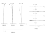
- FIG. 7 is a diagram of various aberrations when focusing on infinity in the wide-angle end state of the variable magnification optical system according to the second example.
- FIG. 4 is a diagram of various aberrations when focusing on infinity in the wide-angle end state of the variable magnification optical system according to the first example.
- FIG. 3 is a diagram of various aberrations when focusing on infinity in the telephoto end
- FIG. 7 is a diagram of various aberrations when focusing on infinity in the telephoto end state of the variable power optical system according to the second example.
- FIG. 7 is a lens configuration diagram in a wide-angle end state of a variable power optical system according to a third example.
- FIG. 7 is a diagram of various aberrations when focusing on infinity in the wide-angle end state of the variable magnification optical system according to the third example.
- FIG. 7 is a diagram of various aberrations when focusing on infinity in the telephoto end state of the variable magnification optical system according to the third example.
- FIG. 7 is a lens configuration diagram in a wide-angle end state of a variable magnification optical system according to a fourth example.
- FIG. 7 is a diagram of various aberrations when focusing on infinity in the wide-angle end state of the variable magnification optical system according to the fourth example.
- FIG. 7 is a diagram of various aberrations when focusing on infinity in the telephoto end state of the variable magnification optical system according to the fourth example.
- FIG. 7 is a lens configuration diagram in a wide-angle end state of a variable magnification optical system according to a fifth embodiment.
- FIG. 7 is a diagram of various aberrations when focusing on infinity in the wide-angle end state of the variable magnification optical system according to the fifth example.
- FIG. 7 is a diagram of various aberrations when focusing on infinity in the telephoto end state of the variable magnification optical system according to the fifth example.
- FIG. 7 is a lens configuration diagram in a wide-angle end state of a variable magnification optical system according to a sixth embodiment.
- FIG. 7 is a diagram of various aberrations when focusing on infinity in the wide-angle end state of the variable magnification optical system according to the sixth embodiment.
- FIG. 7 is a diagram of various aberrations when focusing on infinity in the telephoto end state of the variable power optical system according to the sixth embodiment.
- 1 is a diagram showing the configuration of a camera equipped with a variable magnification optical system according to each embodiment.
- 3 is a flowchart showing a method for manufacturing a variable magnification optical system according to the present invention.
- this camera 1 includes a main body 2 and a photographic lens 3 attached to the main body 2.
- the main body 2 includes an image sensor 4, a main body control section (not shown) that controls the operation of the digital camera, and a liquid crystal screen 5.
- the photographing lens 3 includes a variable magnification optical system ZL including a plurality of lens groups, and a lens position control mechanism (not shown) that controls the position of each lens group.
- the lens position control mechanism includes a sensor that detects the position of the lens group, a motor that moves the lens group back and forth along the optical axis, a control circuit that drives the motor, and the like.
- variable magnification optical system ZL of the photographic lens 3 The light from the subject is collected by the variable magnification optical system ZL of the photographic lens 3 and reaches the image plane I of the image sensor 4.
- the light from the subject that has reached the image plane I is photoelectrically converted by the image sensor 4 and recorded in a memory (not shown) as digital image data.
- the digital image data recorded in the memory can be displayed on the liquid crystal screen 5 in response to user operations.
- this camera may be a mirrorless camera or a single-lens reflex camera with a quick return mirror.
- the variable magnification optical system ZL shown in FIG. 19 is a schematic representation of the variable magnification optical system provided in the photographic lens 3, and the lens configuration of the variable magnification optical system ZL is not limited to this configuration. do not have.
- variable magnification optical system ZL (1) as an example of the variable magnification optical system (zoom lens) ZL according to the present embodiment has negative refractive powers arranged from the object side along the optical axis.
- a first lens group having a positive refractive power a second lens group having a positive refractive power
- a third lens group having a negative refractive power a fourth lens group having a positive refractive power
- variable magnification optical system ZL satisfies the following conditional expressions (1) and (2) under the above configuration. 0.70 ⁇ (-f1)/f2 ⁇ 1.30...(1) 0.55 ⁇ f2/(-f3) ⁇ 1.20...(2)
- f1 Focal length of the first lens group
- f2 Focal length of the second lens group
- f3 Focal length of the third lens group
- variable magnification optical system ZL may be the variable power optical system ZL(2) shown in FIG. 4, the variable power optical system ZL(3) shown in FIG. 7, or the variable power optical system ZL(3) shown in FIG. ZL(4), the variable power optical system ZL(5) shown in FIG. 13, or the variable power optical system ZL(6) shown in FIG. 16 may be used.
- Conditional expression (1) is a conditional expression that defines the ratio of the focal length f1 of the first lens group to the focal length f2 of the second lens group, and defines an appropriate range.
- conditional expression (1) If the corresponding value of conditional expression (1) is less than the lower limit value, the power of the first lens group increases, making it difficult to correct spherical aberration, coma aberration, and curvature of field, which is not preferable.
- the lower limit of conditional expression (1) By setting the lower limit of conditional expression (1) to 0.75 and 0.80, the effects of this embodiment can be made more reliable.
- conditional expression (1) if the corresponding value of conditional expression (1) exceeds the upper limit, the power of the second lens group increases, making it difficult to correct spherical aberration, coma aberration, and curvature of field, which is not preferable.
- the upper limit of conditional expression (1) By setting the upper limit of conditional expression (1) to 1.25 and 1.20, the effects of this embodiment can be made more reliable.
- Conditional expression (2) is a conditional expression that defines the ratio of the focal length f2 of the second lens group to the focal length f3 of the third lens group, and defines an appropriate range.
- conditional expression (2) In the variable magnification optical system, if the corresponding value of conditional expression (2) is less than the lower limit value, the power of the second lens group increases, making it difficult to correct spherical aberration, coma aberration, and curvature of field, which is not preferable.
- the lower limit of conditional expression (2) By setting the lower limit of conditional expression (2) to 0.60 and 0.65, the effects of this embodiment can be made more reliable.
- conditional expression (2) exceeds the upper limit, the power of the third lens group increases, making it difficult to correct spherical aberration, coma aberration, and curvature of field, which is not preferable.
- the upper limit of conditional expression (2) is 1.10 and 1.00, the effects of this embodiment can be made more reliable.
- variable magnification optical system ZL In the variable magnification optical system ZL according to the present embodiment, it is preferable that the following conditional expression (3) is satisfied.
- Conditional expression (3) is a conditional expression that defines the ratio between the focal length f1 of the first lens group and the focal length f4 of the fourth lens group, and defines an appropriate range.
- conditional expression (3) If the corresponding value of conditional expression (3) is less than the lower limit value, the power of the first lens group increases, making it difficult to correct spherical aberration, coma aberration, and curvature of field, which is not preferable.
- the lower limit of conditional expression (3) By setting the lower limit of conditional expression (3) to 0.25 and 0.30, the effects of this embodiment can be made more reliable.
- conditional expression (3) exceeds the upper limit, the power of the fourth lens group increases, making it difficult to correct spherical aberration, coma aberration, and curvature of field, which is not preferable.
- the upper limit of conditional expression (3) 0.45 and 0.42, the effects of this embodiment can be made more reliable.
- variable magnification optical system ZL it is preferable that the following conditional expression (4) is satisfied.
- Conditional expression (4) is a conditional expression that defines the ratio of the focal length f3 of the third lens group to the focal length f4 of the fourth lens group, and defines an appropriate range.
- conditional expression (4) If the corresponding value of conditional expression (4) is less than the lower limit, the power of the third lens group increases, making it difficult to correct spherical aberration, coma aberration, and curvature of field, which is not preferable.
- the lower limit of conditional expression (4) By setting the lower limit of conditional expression (4) to 0.25 and 0.30, the effects of this embodiment can be made more reliable.
- conditional expression (4) if the corresponding value of conditional expression (4) exceeds the upper limit, the power of the fourth lens group increases, making it difficult to correct spherical aberration, coma aberration, and curvature of field, which is not preferable.
- the upper limit of conditional expression (4) By setting the upper limit of conditional expression (4) to 0.80 and 0.70, the effects of this embodiment can be made more reliable.
- variable magnification optical system ZL it is preferable that the following conditional expression (5) is satisfied.
- Conditional expression (5) is a conditional expression that defines the ratio of the focal length f1 of the first lens group to the focal length f3 of the third lens group, and defines an appropriate range.
- conditional expression (5) If the corresponding value of conditional expression (5) is less than the lower limit value, the power of the first lens group increases, making it difficult to correct spherical aberration, coma aberration, and curvature of field, which is not preferable.
- the lower limit of conditional expression (5) By setting the lower limit of conditional expression (5) to 0.55 and 0.60, the effects of this embodiment can be made more reliable.
- conditional expression (5) exceeds the upper limit, the power of the third lens group increases, making it difficult to correct spherical aberration, coma aberration, and curvature of field, which is not preferable.
- the upper limit of conditional expression (5) is 1.00 and 0.90, the effects of this embodiment can be made more reliable.
- variable magnification optical system ZL it is preferable that the following conditional expression (6) is satisfied.
- Conditional expression (6) is a conditional expression that defines the ratio between the focal length f2 of the second lens group and the focal length f4 of the fourth lens group, and defines an appropriate range.
- conditional expression (6) If the corresponding value of conditional expression (6) is less than the lower limit value, the power of the second lens group increases, making it difficult to correct spherical aberration, coma aberration, and curvature of field, which is not preferable.
- the lower limit of conditional expression (6) By setting the lower limit of conditional expression (6) to 0.25 and 0.30, the effects of this embodiment can be made more reliable.
- conditional expression (6) exceeds the upper limit, the power of the fourth lens group increases, making it difficult to correct spherical aberration, coma aberration, and curvature of field, which is not preferable.
- the upper limit of conditional expression (6) 0.60 and 0.50, the effects of this embodiment can be made more reliable.
- variable magnification optical system ZL it is preferable that the following conditional expression (7) is satisfied.
- fw Focal length of the variable power optical system in the wide-angle end state
- TLw Total length of the variable power optical system in the wide-angle end state
- Conditional expression (7) defines the ratio of the focal length fw of the variable magnification optical system in the wide-angle end state to the total length TLw of the variable magnification optical system ZL in the wide-angle end state, and determines an appropriate range. This is a conditional expression for specifying. By satisfying conditional expression (7) in the variable magnification optical system ZL, it is possible to realize a variable magnification optical system having high optical performance while realizing miniaturization.
- conditional expression (7) If the corresponding value of conditional expression (7) is below the lower limit, it becomes difficult to realize a variable magnification optical system that has good optical performance while realizing miniaturization.
- the lower limit of conditional expression (7) By setting the lower limit of conditional expression (7) to 0.125 and 0.130, the effects of this embodiment can be made more reliable.
- conditional expression (7) If the corresponding value of conditional expression (7) exceeds the upper limit, it becomes difficult to realize a variable magnification optical system that has good optical performance while realizing miniaturization.
- the upper limits of conditional expression (7) By setting the upper limits of conditional expression (7) to 0.185 and 0.180, the effects of this embodiment can be made more reliable.
- variable magnification optical system ZL it is preferable that the following conditional expression (8) is satisfied.
- ft Focal length of the variable power optical system in the telephoto end state
- TLt Total length of the variable power optical system in the telephoto end state
- Conditional expression (8) defines the ratio of the focal length ft of the variable power optical system in the telephoto end state to the total length TLt of the variable power optical system ZL in the telephoto end state, and determines an appropriate range. This is a conditional expression for specifying.
- conditional expression (8) If the corresponding value of conditional expression (8) is below the lower limit, it becomes difficult to realize a variable magnification optical system that has good optical performance while realizing miniaturization.
- the lower limit of conditional expression (8) By setting the lower limit of conditional expression (8) to 0.25 and 0.30, the effects of this embodiment can be made more reliable.
- conditional expression (8) If the corresponding value of conditional expression (8) exceeds the upper limit, it becomes difficult to realize a variable magnification optical system that has good optical performance while realizing miniaturization.
- the upper limits of conditional expression (8) By setting the upper limits of conditional expression (8) to 0.45 and 0.40, the effects of this embodiment can be made more reliable.
- variable magnification optical system ZL In the variable magnification optical system ZL according to the present embodiment, it is preferable that the following conditional expression (9) is satisfied.
- Mv2 Amount of movement of the second lens group when changing the magnification from the wide-angle end state to the telephoto end state
- Conditional expression (9) defines the ratio of the movement amount Mv2 of the second lens group to the focal length f2 of the second lens group when changing power from the wide-angle end state to the telephoto end state, and defines an appropriate range. This is a conditional expression for By satisfying conditional expression (9) in the variable magnification optical system ZL, it is possible to realize a variable magnification optical system having good optical performance while realizing miniaturization.
- conditional expression (9) If the corresponding value of conditional expression (9) is below the lower limit, it becomes difficult to realize a variable magnification optical system that has good optical performance while realizing miniaturization.
- the lower limit of conditional expression (9) By setting the lower limit of conditional expression (9) to 0.75 and 0.80, the effects of this embodiment can be made more reliable.
- conditional expression (9) exceeds the upper limit, it becomes difficult to correct spherical aberration, coma aberration, and field curvature, which is not preferable.
- the upper limit of conditional expression (9) is 1.25 and 1.20, the effects of this embodiment can be made more reliable.
- variable magnification optical system ZL In the variable magnification optical system ZL according to the present embodiment, it is preferable that the following conditional expression (10) is satisfied.
- Mv3 Amount of movement of the third lens group when changing the magnification from the wide-angle end state to the telephoto end state
- Conditional expression (10) defines the ratio of the movement amount Mv3 of the third lens group to the focal length f3 of the third lens group when changing the magnification from the wide-angle end state to the telephoto end state, and defines an appropriate range. This is a conditional expression for When changing the magnification from the wide-angle end state to the telephoto end state, the third lens group moves toward the object side, and at this time, the variable power optical system ZL satisfies conditional expression (10), thereby realizing miniaturization. At the same time, it is possible to realize a variable power optical system having good optical performance.
- conditional expression (10) If the corresponding value of conditional expression (10) is below the lower limit, it becomes difficult to achieve good optical performance while realizing miniaturization. In order to ensure the effect of conditional expression (10), it is more preferable to set the lower limit to 0.37 or 0.38.
- conditional expression (10) exceeds the upper limit, the power of the third lens group increases, making it difficult to correct spherical aberration, coma aberration, and curvature of field, which is not preferable.
- the amount of movement Mv3 of the third lens group during zooming increases, making it difficult to downsize the optical system.
- variable magnification optical system has a diaphragm disposed within a second lens group, and the second lens group has an anti-vibration lens group disposed closer to the image plane than the diaphragm.
- variable magnification optical system ZL In the variable magnification optical system ZL according to the present embodiment, it is preferable that the following conditional expression (11) is satisfied.
- Conditional expression (11) is a conditional expression that defines the ratio of the focal length fvr of the anti-shake lens group to the focal length f2 of the second lens group, and defines an appropriate range.
- conditional expression (11) If the corresponding value of conditional expression (11) is less than the lower limit, the power of the anti-vibration lens group increases, making it difficult to correct spherical aberration, coma aberration, and curvature of field, which is not preferable.
- the lower limit of conditional expression (11) By setting the lower limit of conditional expression (11) to 1.30 and 1.40, the effects of this embodiment can be made more reliable.
- conditional expression (11) exceeds the upper limit, the power of the second lens group increases, making it difficult to correct spherical aberration, coma aberration, and curvature of field, which is not preferable.
- the upper limit of conditional expression (11) is 2.10 and 2.00, the effects of this embodiment can be made more reliable.
- variable magnification optical system ZL In the variable magnification optical system ZL according to the present embodiment, it is preferable that the following conditional expression (12) is satisfied.
- Mv2 Amount of movement of the second lens group when changing power from the wide-angle end state to the telephoto end state
- Mv3 Amount of movement of the third lens group when changing power from the wide-angle end state to the telephoto end state
- Conditional expression (12) is a conditional expression for defining the ratio of the moving amount Mv2 of the second lens group and the moving amount Mv3 of the third lens group during zooming, and defining an appropriate range.
- conditional expression (12) If the corresponding value of conditional expression (12) is less than the lower limit value, the movement amount Mv2 of the second lens group during zooming becomes small, making it difficult to correct spherical aberration, coma aberration, and curvature of field, which is not preferable. On the other hand, the amount of movement Mv3 of the third lens group increases, making it difficult to achieve miniaturization. In order to ensure the effect of conditional expression (12), it is more preferable to set the lower limit to 1.10 or 1.20.
- conditional expression (12) exceeds the upper limit, the amount of movement Mv3 of the third lens group during zooming becomes small, making it difficult to correct spherical aberration, coma aberration, and curvature of field, which is preferable. do not have.
- the amount of movement Mv2 of the second lens group increases, making it difficult to achieve miniaturization.
- variable magnification optical system it is preferable that focusing from an object at infinity to an object at a short distance is performed by moving the third lens group on the optical axis.
- focusing from an object at infinity to an object at a short distance is performed by moving the third lens group on the optical axis.
- variable power optical system when changing the power from the wide-angle end state to the telephoto end state, the second lens group and the third lens group move toward the object side, and the first lens group and the second lens group It is preferable that the distance between the third lens group and the fourth lens group increases. As a result, it is possible to realize a variable power optical system that has good optical performance with less movement of the center of gravity when changing power from the wide-angle end state to the telephoto end state.
- variable magnification optical system it is preferable that the fourth lens group is fixed to the image plane during variable magnification.
- the fourth lens group is fixed to the image plane, so that the entire length of the zooming optical system can be changed without changing. It is possible to realize a variable magnification optical system that can perform magnification and has good optical performance with little movement of the center of gravity.
- variable magnification optical system ZL In the variable magnification optical system ZL according to the present embodiment, it is preferable that the following conditional expression (13) is satisfied.
- Mv2 Amount of movement of the second lens group during zooming from the wide-angle end state to the telephoto end state
- TL Total length of the zooming optical system
- Conditional expression (13) is a conditional expression that defines the ratio between the movement amount Mv2 of the second lens group during zooming and the total length TL of the zooming optical system, and defines an appropriate range.
- the total length TL of the variable power optical system may be the total length (TLw) of the variable power optical system in the wide-angle end state, or the total length (TLt) of the variable power optical system in the telephoto end state.
- variable magnification optical system ZL In the variable magnification optical system ZL according to the present embodiment, it is preferable that the following conditional expression (14) is satisfied.
- Mv3 Amount of movement of the third lens group during zooming from the wide-angle end state to the telephoto end state TL: Total length of the zooming optical system
- Conditional expression (14) is a conditional expression that defines the ratio between the movement amount Mv3 of the third lens group during zooming and the total length TL of the zooming optical system, and defines an appropriate range.
- the total length TL of the variable power optical system may be the total length (TLw) of the variable power optical system in the wide-angle end state, or the total length (TLt) of the variable power optical system in the telephoto end state.
- variable magnification optical system ZL having the above-described configuration
- a first lens group having a negative refractive power, a second lens group having a positive refractive power, a third lens group having a negative refractive power, and a positive refractive power is arranged (step ST10), and during zooming, the first lens group is fixed to the image plane and the distance between adjacent lens groups is changed ( Step ST20). Then, each lens is arranged within the lens barrel so that at least conditional expressions (1) and (2) are satisfied (step ST30). According to such a manufacturing method, it is possible to obtain a variable power optical system ZL that is small and has good optical performance.
- FIG. 1 shows the configuration and refractive power distribution of the variable magnification optical system ZL ⁇ ZL(1) to ZL(6) ⁇ according to the first to sixth embodiments.
- FIG. The first to sixth embodiments are examples corresponding to this embodiment, and each figure shows a lens group that moves during zooming from the wide-angle end state (W) to the telephoto end state (T). The direction of movement along the optical axis is indicated by an arrow. Furthermore, the lens group that moves when focusing on a short distance object from infinity is referred to as a focusing lens group GF, and the moving direction is indicated by an arrow together with the word "focus".
- the second lens group constitutes an anti-vibration lens group GVR that can move in a direction perpendicular to the optical axis, and corrects displacement of the imaging position (image blur on the image plane I) due to camera shake, etc. do.
- the direction in which the anti-shake lens group moves when correcting image blur is indicated by an arrow along with the word "anti-shake.”
- each lens group is represented by a combination of a symbol G and a number
- each lens is represented by a combination of a symbol L and a number.
- lens groups and the like are expressed using combinations of codes and numbers independently for each embodiment. Therefore, even if the same combination of symbols and numbers is used between the embodiments, it does not mean that they have the same configuration.
- the sign (+) or (-) attached to each lens group symbol indicates the refractive power of each lens group, and this is the same in all the examples below.
- Tables 1 to 6 are shown below, of which Table 1 is the first example, Table 2 is the second example, Table 3 is the third example, Table 4 is the fourth example, and Table 5 is the fifth example.
- Table 6 is a table showing each specification data in the sixth example.
- f is the focal length of the entire optical system
- FNO is the F number
- ⁇ is the half angle of view (in degrees (degrees))
- Y is the image height.
- TL indicates the total length of the optical system. Specifically, it indicates the distance obtained by adding BF to the distance from the frontmost lens surface to the final lens surface on the optical axis when focusing on infinity, and BF is the distance when focusing on infinity. The air equivalent distance (back focus) from the final lens surface to the image plane I on the optical axis is shown. Note that these values are shown for each zooming state: wide-angle end (wide), intermediate focal length (middle), and telephoto end (tele). Further, in the [Overall specifications] table, fvr indicates the focal length of the anti-vibration lens group GVR.
- the surface number indicates the order of the optical surfaces from the object side along the direction of propagation of the light ray
- R is the radius of curvature of each optical surface (the surface whose center of curvature is located on the image side).
- D is the distance between each optical surface and the next optical surface (or image surface) on the optical axis
- nd is the refractive index of the material of the optical member with respect to the d-line.
- the radius of curvature " ⁇ " indicates a plane or an aperture
- (diaphragm S) indicates an aperture diaphragm.
- the description of the refractive index nd 1.00000 of air is omitted.
- the [Lens Group Data] table shows the focal length of each lens group.
- the [Variable spacing data] table shows the surface spacing for surface numbers for which the surface spacing is "variable” in the table showing [Lens specifications].
- the surface spacing in each zooming state at the wide-angle end (wide), intermediate focal length (middle), and telephoto end (tele) is shown when focusing on infinity and short distances, respectively.
- f indicates the focal length of the entire optical system.
- the table of [Values corresponding to conditional expressions] shows the values corresponding to each conditional expression.
- the focal length f, radius of curvature R, surface spacing D, and other lengths are generally expressed in mm unless otherwise specified, but the optical system is proportionally enlarged. Alternatively, even if the optical performance is proportionally reduced, the same optical performance can be obtained, so the present invention is not limited to this.
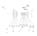
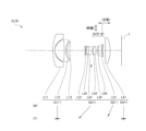
- FIG. 1 is a lens configuration diagram in a wide-angle end state of a variable magnification optical system ZL (ZL(1)) according to a first embodiment.
- the variable magnification optical system ZL(1) according to the first embodiment includes a first lens group G1 having a negative refractive power and a second lens group having a positive refractive power, which are arranged in order from the object side along the optical axis. It has a lens group G2, a third lens group G3 having a negative refractive power, and a fourth lens group G4 having a positive refractive power.
- the distance between the first lens group G1 and the second lens group G2 decreases, and the distance between the third lens group G3 and the fourth lens group G4 decreases.
- the second lens group G2 and the third lens group G3 move their optical axes on different trajectories so that the optical axis increases. More specifically, during zooming, the second lens group G2 monotonically moves toward the object side along the optical axis, the third lens group G3 monotonically moves toward the object side along the optical axis, and the first lens group G2 monotonically moves toward the object side along the optical axis.
- Group G1 and fourth lens group G4 are fixed.
- the first lens group G1 includes a meniscus-shaped positive lens L11 with a convex surface facing the object side, a meniscus-shaped negative lens L12 with a convex surface facing the object side, and a biconcave lens arranged in order from the object side along the optical axis. It has a negative lens L13 having a negative shape, and a positive lens L14 having a meniscus shape with a convex surface facing the object side.
- the second lens group G2 includes a biconvex positive lens L21, a meniscus positive lens L22 with its convex surface facing the object side, and a biconcave negative lens arranged in order from the object side along the optical axis.
- the positive lens L24 and the negative lens L25 are cemented together to form a cemented lens.
- the third lens group G3 includes a biconcave negative lens L31.
- the fourth lens group G4 is composed of a positive lens L41 with a convex surface facing the image plane side.
- An image plane I is arranged on the image side of the fourth lens group.
- the aperture stop S whose purpose is to adjust the amount of light, is placed in the second lens group, and moves on the same trajectory as the second lens group G2 during zooming from the wide-angle end state to the telephoto end state. do.
- the lenses disposed closer to the image plane than the aperture stop S in the second lens group G2 constitute an anti-vibration lens group GVR that can move in a direction perpendicular to the optical axis, so that displacement of the imaging position due to camera shake, etc. (image blur on image plane I) is corrected.
- the cemented lens of the positive lens L24 and the negative lens L25 in the second lens group G2 constitutes the anti-vibration lens group GVR.
- the third lens group G3 corresponds to the focusing lens group GF that moves along the optical axis.
- the focusing lens group GF moves toward the image plane along the optical axis.
- the 19th lens surface is formed into an aspherical shape.
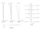
- FIGS. 2 and 3 are diagrams of various aberrations of the variable magnification optical system ZL(1) according to the first example.
- FNO indicates the F number
- Y indicates the image height.
- the solid line indicates the sagittal image plane
- the broken line indicates the meridional image plane.
- meridional coma is shown. The above description of the aberration diagrams is the same for other embodiments.
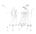
- FIG. 4 is a lens configuration diagram in the wide-angle end state of the variable magnification optical system ZL (ZL(2)) according to the second embodiment.
- the variable magnification optical system ZL(2) according to the second embodiment includes a first lens group G1 having a negative refractive power and a second lens group having a positive refractive power, which are arranged in order from the object side along the optical axis. It has a lens group G2, a third lens group G3 having a negative refractive power, and a fourth lens group G4 having a positive refractive power.
- the distance between the first lens group G1 and the second lens group G2 decreases, and the distance between the third lens group G3 and the fourth lens group G4 decreases.
- the second lens group G2 and the third lens group G3 move their optical axes on different trajectories so that the optical axis increases. More specifically, during zooming, the second lens group G2 monotonically moves toward the object side along the optical axis, the third lens group G3 monotonically moves toward the object side along the optical axis, and the first lens group G2 monotonically moves toward the object side along the optical axis.
- Group G1 and fourth lens group G4 are fixed.
- the first lens group G1 includes a meniscus-shaped positive lens L11 with a convex surface facing the object side, a meniscus-shaped negative lens L12 with a convex surface facing the object side, and a biconcave lens arranged in order from the object side along the optical axis. It has a negative lens L13 having a negative shape, and a positive lens L14 having a meniscus shape with a convex surface facing the object side.
- the second lens group G2 includes a biconvex positive lens L21, a meniscus positive lens L22 with a convex surface facing the object side, an aperture stop S, and an object side, which are arranged in order from the object side along the optical axis.
- a meniscus-shaped negative lens L23 with a convex surface facing , a biconvex positive lens L24, a biconvex positive lens L25, a biconcave negative lens L26, and a biconvex positive lens L27. has and is constituted.
- the negative lens L23 and the positive lens L24 are cemented together to form a cemented lens.
- the positive lens L25 and the negative lens L26 are cemented together to form a cemented lens.
- the third lens group G3 is composed of a biconcave negative lens L31.
- the fourth lens group G4 is composed of a positive lens L41 with a convex surface facing the image plane side.
- An image plane I is arranged on the image side of the fourth lens group.
- the aperture stop S whose purpose is to adjust the amount of light, is placed in the second lens group, and moves on the same trajectory as the second lens group G2 during zooming from the wide-angle end state to the telephoto end state. do.
- the lenses disposed closer to the image plane than the aperture stop S in the second lens group G2 constitute an anti-vibration lens group GVR that can move in a direction perpendicular to the optical axis, so that displacement of the imaging position due to camera shake, etc. (image blur on image plane I) is corrected.
- the cemented lens of the positive lens L25 and the negative lens L26 and the positive lens L27 constitute the anti-vibration lens group GVR.
- the lens group G3 corresponds to a focusing lens group GF that moves along the optical axis. When focusing from an object at infinity to an object at a short distance, the focusing lens group GF moves toward the image plane along the optical axis.
- Table 2 below shows each specification in the second example. Further, in the second embodiment, the 23rd lens surface is formed into an aspherical shape.
- FIG. 7 is a lens configuration diagram in the wide-angle end state of the variable magnification optical system ZL (ZL(3)) according to the third embodiment.
- the variable magnification optical system ZL(3) according to the third embodiment includes a first lens group G1 having a negative refractive power and a second lens group having a positive refractive power, which are arranged in order from the object side along the optical axis. It has a lens group G2, a third lens group G3 having a negative refractive power, and a fourth lens group G4 having a positive refractive power.
- the distance between the first lens group G1 and the second lens group G2 decreases, and the distance between the third lens group G3 and the fourth lens group G4 decreases.
- the second lens group G2 and the third lens group G3 move their optical axes on different trajectories so that the optical axis increases. More specifically, during zooming, the second lens group G2 monotonically moves toward the object side along the optical axis, the third lens group G3 monotonically moves toward the object side along the optical axis, and the first lens group G2 monotonically moves toward the object side along the optical axis.
- G1 and the fourth lens group G4 are fixed.
- the first lens group G1 includes a meniscus-shaped first positive lens L11 with a convex surface facing the object side and a second meniscus-shaped negative lens L12 with a convex surface facing the object side, which are arranged in order from the object side along the optical axis. , a biconcave third negative lens L13, and a meniscus fourth positive lens L14 with a convex surface facing the object side.
- the second lens group G2 includes a meniscus-shaped positive lens L21 with a convex surface facing the object side, which is arranged in order from the object side along the optical axis, a biconcave negative lens L22, and a biconvex positive lens L23. , an aperture stop S, a meniscus-shaped negative lens L24 with a convex surface facing the object side, a meniscus-shaped positive lens L25 with a convex surface facing the object side, and a double-convex positive lens L26. , configured.
- the negative lens L22 and the positive lens L23 are cemented together to form a cemented lens. Further, the negative lens L24 and the positive lens L25 are cemented together to form a cemented lens.
- the third lens group G3 includes a biconcave negative lens L31.
- the fourth lens group G4 is composed of a positive lens L41 with a convex surface facing the image plane side.
- An image plane I is arranged on the image side of the fourth lens group.
- the aperture stop S whose purpose is to adjust the amount of light, is placed in the second lens group, and moves on the same trajectory as the second lens group G2 during zooming from the wide-angle end state to the telephoto end state. do.
- the lenses disposed closer to the image plane than the aperture stop S in the second lens group G2 constitute an anti-vibration lens group GVR that can move in a direction perpendicular to the optical axis, so that displacement of the imaging position due to camera shake, etc. (image blur on image plane I) is corrected.
- the cemented lens in which the negative lens L24 and the positive lens L25 in the second lens group G2 are cemented together, and the biconvex positive lens L26 constitute the anti-vibration lens group GVR.
- the third lens group G3 corresponds to the focusing lens group GF that moves along the optical axis.
- the focusing lens group GF moves toward the image plane along the optical axis.
- the 21st lens surface is formed into an aspherical shape.
- FIG. 10 is a lens configuration diagram in the wide-angle end state of the variable magnification optical system ZL (ZL(4)) according to the fourth embodiment.
- the variable magnification optical system ZL(4) according to the fourth embodiment includes a first lens group G1 having a negative refractive power and a second lens group having a positive refractive power, which are arranged in order from the object side along the optical axis.
- a lens group G2, a third lens group G3 having a negative refractive power, and a fourth lens group G4 having a positive refractive power are configured.
- the distance between the first lens group G1 and the second lens group G2 decreases, and the distance between the third lens group G3 and the fourth lens group G4 decreases.
- the second lens group G2 and the third lens group G3 move their optical axes on different trajectories so that the optical axis increases. More specifically, during zooming, the second lens group G2 monotonically moves toward the object side along the optical axis, the third lens group G3 monotonically moves toward the object side along the optical axis, and the first lens group G2 monotonically moves toward the object side along the optical axis.
- Group G1 and fourth lens group G4 are fixed.
- the first lens group G1 includes a meniscus-shaped positive lens L11 with a convex surface facing the object side, a meniscus-shaped negative lens L12 with a convex surface facing the object side, and a biconcave lens arranged in order from the object side along the optical axis. It has a negative lens L13 having a negative shape, and a positive lens L14 having a meniscus shape with a convex surface facing the object side.
- the second lens group G2 includes a biconvex positive lens L21, a meniscus positive lens L22 with a convex surface facing the object side, and a meniscus positive lens L22 with a convex surface facing the image side, which are arranged in order from the object side along the optical axis.
- the positive lens L24 and the negative lens L25 are cemented together to form a cemented lens.
- the third lens group G3 includes a biconcave negative lens L31.
- the fourth lens group G4 is composed of a positive lens L41 with a convex surface facing the image plane side.
- An image plane I is arranged on the image side of the fourth lens group.
- the aperture stop S whose purpose is to adjust the amount of light, is placed in the second lens group, and moves on the same trajectory as the second lens group G2 during zooming from the wide-angle end state to the telephoto end state. do.
- the lenses disposed closer to the image plane than the aperture stop S in the second lens group G2 constitute an anti-vibration lens group GVR that can move in a direction perpendicular to the optical axis, so that displacement of the imaging position due to camera shake, etc. (image blur on image plane I) is corrected.
- a cemented lens in which the positive lens L24 and the negative lens L25 in the second lens group G2 are cemented together constitutes the anti-vibration lens group GVR.
- the third lens group G3 corresponds to the focusing lens group GF that moves along the optical axis.
- the focusing lens group GF moves toward the image plane along the optical axis.
- the 19th lens surface is formed into an aspherical shape.
- FIG. 13 is a lens configuration diagram in the wide-angle end state of the variable magnification optical system ZL (ZL(5)) according to the fifth embodiment.
- the variable magnification optical system ZL(5) according to the fifth embodiment includes a first lens group G1 having a negative refractive power and a second lens group having a positive refractive power, which are arranged in order from the object side along the optical axis. It has a lens group G2, a third lens group G3 having a negative refractive power, and a fourth lens group G4 having a positive refractive power.
- the distance between the first lens group G1 and the second lens group G2 decreases, and the distance between the third lens group G3 and the fourth lens group G4 decreases.
- the second lens group G2 and the third lens group G3 move their optical axes on different trajectories so that the optical axis increases. More specifically, during zooming, the second lens group G2 monotonically moves toward the object side along the optical axis, the third lens group G3 monotonically moves toward the object side along the optical axis, and the first lens group G2 monotonically moves toward the object side along the optical axis.
- Group G1 and fourth lens group G4 are fixed.
- the first lens group G1 includes a meniscus-shaped negative lens L11 with a convex surface facing the object side, a meniscus-shaped negative lens L12 with a convex surface facing the object side, which are arranged in order from the object side along the optical axis. It has a meniscus-shaped positive lens L13 with a convex surface facing the side.
- the negative lens L11 is a hybrid lens configured by providing a resin layer on the image plane side of a glass lens body.
- the image plane side surface of the resin layer is an aspherical surface
- the negative lens L11 is a composite aspherical lens.
- surface number 1 is the object-side surface of the lens body
- surface number 2 is the image-side surface of the lens body
- the object-shaped surface of the resin layer (the surface where the two join)
- the surface indicates the surface of the resin layer on the image plane side.
- the second lens group G2 includes a biconvex positive lens L21, a meniscus negative lens L22 with a convex surface facing the object side, and a biconvex positive lens L23, which are arranged in order from the object side along the optical axis. , an aperture stop S, a meniscus negative lens L24 with a convex surface facing the object side, a biconvex positive lens L25, and a biconvex positive lens L26.
- the negative lens L22 and the positive lens L23 are cemented together to form a cemented lens. Further, the negative lens L24 and the positive lens L25 are cemented together to form a cemented lens.
- the third lens group G3 is composed of a meniscus-shaped negative lens L31 with a convex surface facing the object side.
- the fourth lens group G4 is composed of a positive lens L41 with a convex surface facing the image plane side.
- An image plane I is arranged on the image side of the fourth lens group.
- the aperture stop S whose purpose is to adjust the amount of light, is placed in the second lens group, and moves on the same trajectory as the second lens group G2 during zooming from the wide-angle end state to the telephoto end state. do.
- the lenses disposed closer to the image plane than the aperture stop S in the second lens group G2 constitute an anti-vibration lens group GVR that can move in a direction perpendicular to the optical axis, so that displacement of the imaging position due to camera shake, etc. (image blur on image plane I) is corrected.
- the cemented lens in which the negative lens L24 and the positive lens L25 in the second lens group G2 are cemented, and the positive lens L26 constitute the anti-vibration lens group GVR.
- the third lens group G3 corresponds to the focusing lens group GF that moves along the optical axis.
- the focusing lens group GF moves toward the image plane along the optical axis.
- each of the third, eighth, and nineteenth lens surfaces is formed into an aspherical shape.
- FIG. 18 is a lens configuration diagram in the wide-angle end state of the variable magnification optical system ZL (ZL(6)) according to the sixth embodiment.
- the variable magnification optical system ZL(6) according to the sixth embodiment includes a first lens group G1 having a negative refractive power and a second lens group having a positive refractive power, which are arranged in order from the object side along the optical axis. It has a lens group G2, a third lens group G3 having a negative refractive power, and a fourth lens group G4 having a positive refractive power.
- the distance between the first lens group G1 and the second lens group G2 decreases, and the distance between the third lens group G3 and the fourth lens group G4 decreases.
- the second lens group G2 and the third lens group G3 move their optical axes on different trajectories so that the optical axis increases. More specifically, during zooming, the second lens group G2 monotonically moves toward the object side along the optical axis, the third lens group G3 monotonically moves toward the object side along the optical axis, and the first lens group G2 monotonically moves toward the object side along the optical axis.
- Group G1 and fourth lens group G4 are fixed.
- the first lens group G1 includes a meniscus-shaped negative lens L11 with a convex surface facing the object side, a biconcave negative lens L12, and a negative lens L12 with a biconcave surface, which are arranged in order from the object side along the optical axis. It has a meniscus-shaped positive lens L13, and is configured.
- the negative lens L11 is a hybrid lens configured by providing a resin layer on the image plane side of a glass lens body.
- the image plane side surface of the resin layer is an aspherical surface
- the negative lens L11 is a composite aspherical lens.
- surface number 1 is the object-side surface of the lens body
- surface number 2 is the image-side surface of the lens body
- the object-shaped surface of the resin layer (the surface where the two join)
- the surface indicates the surface of the resin layer on the image plane side.
- the second lens group G2 includes a meniscus-shaped positive lens L21 with a convex surface facing the object side, a meniscus-shaped negative lens L22 with a convex surface facing the object side, which are arranged in order from the object side along the optical axis.
- the negative lens L22 and the positive lens L23 are cemented together to form a cemented lens. Further, the negative lens L24 and the positive lens L25 are cemented together to form a cemented lens.
- the third lens group G3 is composed of a biconcave negative lens L31.
- the fourth lens group G4 is composed of a positive lens L41 with a convex surface facing the image plane side.
- An image plane I is arranged on the image side of the fourth lens group.
- the negative lens L31 is a hybrid lens configured by providing a resin layer on the image plane side of a glass lens body.
- the image plane side surface of the resin layer is an aspherical surface
- the negative lens L31 is a composite aspherical lens.
- surface number 19 is the object-side surface of the lens body
- surface number 20 is the image-side surface of the lens body
- the object-shaped surface of the resin layer (the surface where the two join)
- the surface. Number 21 indicates the surface of the resin layer on the image plane side.
- the aperture stop S whose purpose is to adjust the amount of light, is placed in the second lens group, and moves on the same trajectory as the second lens group G2 during zooming from the wide-angle end state to the telephoto end state. do.
- the lenses disposed closer to the image plane than the aperture stop S in the second lens group G2 constitute an anti-vibration lens group GVR that can move in a direction perpendicular to the optical axis, so that displacement of the imaging position due to camera shake, etc. (image blur on image plane I) is corrected.
- the cemented lens in which the negative lens L24 and the positive lens L25 in the second lens group G2 are cemented, and the negative lens L26 constitute the anti-vibration lens group GVR.
- the third lens group G3 corresponds to the focusing lens group GF that moves along the optical axis.
- the focusing lens group GF moves toward the image plane along the optical axis.
- each of the third, seventeenth, eighteenth, and twenty-first lens surfaces is formed into an aspherical shape.
- Conditional expression (1) 0.70 ⁇ (-f1)/f2 ⁇ 1.30 Conditional expression (2) 0.55 ⁇ f2/(-f3) ⁇ 1.20 Conditional expression (3) 0.20 ⁇ (-f1)/f4 ⁇ 0.50 Conditional expression (4) 0.20 ⁇ (-f3)/f4 ⁇ 0.90 Conditional expression (5) 0.50 ⁇ f1/f3 ⁇ 1.10 Conditional expression (6) 0.20 ⁇ f2/f4 ⁇ 0.70 Conditional expression (7) 0.120 ⁇ fw/TLw ⁇ 0.190 Conditional expression (8) 0.20 ⁇ ft/TLt ⁇ 0.50 Conditional expression (9) 0.70 ⁇ Mv2/f2 ⁇ 1.30 Conditional expression (10) 0.36 ⁇ Mv3/(-f3) ⁇ 0.80 Conditional expression (11) 1.20 ⁇ fvr/f2 ⁇ 2.20 Conditional expression (1) 0.70 ⁇ (-f1)/f2 ⁇ 1.30 Conditional expression (2) 0.55 ⁇ f2/(-f3) ⁇ 1.20 Conditional expression (3) 0.20
- a four-group configuration is shown as a variable magnification optical system, but it is also applicable to other group configurations such as five groups. Further, a configuration in which a lens or a lens group is added to the closest to the object side, or a configuration in which a lens or a lens group is added to the closest to the image side may be used. Further, the lens group refers to a portion having at least one lens separated by an air gap that changes when changing the magnification.
- a focusing lens group may be used that focuses from an object at infinity to an object at a short distance by moving one or more lens groups, or a partial lens group in the optical axis direction.
- This focusing lens group can also be applied to autofocus, and is also suitable for driving a motor (using an ultrasonic motor or the like) for autofocus.
- variable power optical system of each embodiment not only a part of the lenses in the second lens group but also a lens group or a partial lens group is moved so as to have a component in a direction perpendicular to the optical axis, or the optical axis is It may also be used as an anti-vibration lens group that rotates (swings) in the in-plane direction to correct image blur caused by camera shake.
- the lens surface may be formed as a spherical surface, a flat surface, or an aspherical surface. It is preferable that the lens surface is spherical or flat because it facilitates lens processing and assembly adjustment and prevents deterioration of optical performance due to errors in processing and assembly adjustment. Further, even if the image plane shifts, there is little deterioration in depiction performance, which is preferable.
- the aspherical surface can be an aspherical surface made by grinding, a glass molded aspherical surface made by molding glass into an aspherical shape, or a composite aspherical surface made by molding resin into an aspherical shape on the glass surface. Either is fine.
- the lens surface may be a diffractive surface, and the lens may be a gradient index lens (GRIN lens) or a plastic lens.
- the aperture stop is placed within the second lens group, the role of the aperture stop may be substituted by the frame of the lens without providing a member serving as the aperture stop.
- Each lens surface may be coated with an antireflection film that has high transmittance in a wide wavelength range in order to reduce flare and ghosting and achieve high optical performance with high contrast.
- variable magnification optical system of this embodiment is used in a camera, it is not limited to this, and may be used in an optical device such as a camera with a video shooting function.
Abstract
変倍光学系(ZL)は、光軸に沿って物体側から順に並んだ、負の屈折力を有する第1レンズ群(G1)と、正の屈折力を有する第2レンズ群(G2)と、負の屈折力を有する第3レンズ群(G3)と、正の屈折力を有する第4レンズ群(G4)とを有し、変倍の際、第1レンズ群(G1)が像面に対して固定され、隣り合う各レンズ群の間隔が変化して、以下の条件式を満足する。 0.70 < (-f1)/f2 < 1.30 0.55 < f2/(-f3) < 1.20 但し、 f1:前記第1レンズ群の焦点距離 f2:前記第2レンズ群の焦点距離 f3:前記第3レンズ群の焦点距離
Description
本発明は、変倍光学系、光学機器、および変倍光学系の製造方法に関する。
従来から、写真用カメラ、電子スチルカメラ、ビデオカメラ等に適した変倍光学系が提案されている(例えば、特許文献1を参照)。しかしながら、このような変倍光学系においては、小型化を実現しつつ良好な光学性能を得ることが難しい。
本発明に係る変倍光学系は、光軸に沿って物体側から順に並んだ、負の屈折力を有する第1レンズ群と、正の屈折力を有する第2レンズ群と、負の屈折力を有する第3レンズ群と、正の屈折力を有する第4レンズ群とを有した変倍光学系であって、変倍の際、第1レンズ群が像面に対して固定され、隣り合う各レンズ群の間隔が変化して、以下の条件式を満足する。
0.70 < (-f1)/f2 < 1.30
0.55 < f2/(-f3) < 1.20
但し、 f1:前記第1レンズ群の焦点距離
f2:前記第2レンズ群の焦点距離
f3:前記第3レンズ群の焦点距離
0.70 < (-f1)/f2 < 1.30
0.55 < f2/(-f3) < 1.20
但し、 f1:前記第1レンズ群の焦点距離
f2:前記第2レンズ群の焦点距離
f3:前記第3レンズ群の焦点距離
本発明に係る光学機器は、上記変倍光学系を備えて構成される。
本発明に係る変倍光学系の製造方法は、光軸に沿って物体側から順に並んだ、負の屈折力を有する第1レンズ群と、正の屈折力を有する第2レンズ群と、負の屈折力を有する第3レンズ群と、正の屈折力を有する第4レンズ群とを有した変倍光学系の製造方法であって、変倍の際、第1レンズ群が像面に対して固定され、隣り合う各レンズ群の間隔が変化して、以下の条件式を満足するように、レンズ鏡筒内に各レンズを配置するステップを有する。
0.70 < (-f1)/f2 < 1.30
0.55 < f2/(-f3) < 1.20
但し、 f1:前記第1レンズ群の焦点距離
f2:前記第2レンズ群の焦点距離
f3:前記第3レンズ群の焦点距離
0.70 < (-f1)/f2 < 1.30
0.55 < f2/(-f3) < 1.20
但し、 f1:前記第1レンズ群の焦点距離
f2:前記第2レンズ群の焦点距離
f3:前記第3レンズ群の焦点距離
以下、本発明に係る好ましい実施形態について説明する。まず、各実施形態に係る変倍光学系を備えたカメラ(光学機器)を図19に基づいて説明する。このカメラ1は、図19に示すように、本体2と、本体2に装着される撮影レンズ3により構成される。本体2は、撮像素子4と、デジタルカメラの動作を制御する本体制御部(不図示)と、液晶画面5とを備える。撮影レンズ3は、複数のレンズ群からなる変倍光学系ZLと、各レンズ群の位置を制御するレンズ位置制御機構(不図示)とを備える。レンズ位置制御機構は、レンズ群の位置を検出するセンサと、レンズ群を光軸に沿って前後に移動させるモータと、モータを駆動する制御回路などにより構成される。
被写体からの光は、撮影レンズ3の変倍光学系ZLにより集光されて、撮像素子4の像面I上に到達する。像面Iに到達した被写体からの光は、撮像素子4により光電変換され、デジタル画像データとして不図示のメモリに記録される。メモリに記録されたデジタル画像データは、ユーザの操作に応じて液晶画面5に表示することが可能である。なお、このカメラは、ミラーレスカメラでも、クイックリターンミラーを有した一眼レフタイプのカメラであっても良い。また、図19に示す変倍光学系ZLは、撮影レンズ3に備えられる変倍光学系を模式的に示したものであり、変倍光学系ZLのレンズ構成はこの構成に限定されるものではない。
次に、本実施形態に係る変倍光学系について説明する。本実施形態に係る変倍光学系(ズームレンズ)ZLの一例としての変倍光学系ZL(1)は、図1に示すように、光軸に沿って物体側から並んだ、負の屈折力を有する第1レンズ群と、正の屈折力を有する第2レンズ群と、負の屈折力を有する第3レンズ群と、正の屈折力を有する第4レンズ群とを有して構成され、変倍の際、第1レンズ群が像面に対して固定され、隣り合う各レンズ群の間隔が変化する。
本実施形態に係る変倍光学系ZLは、上記構成の下、以下の条件式(1)、(2)を満足する。
0.70 < (-f1)/f2 < 1.30 ・・・(1)
0.55 < f2/(-f3) < 1.20 ・・・(2)
但し、f1:第1レンズ群の焦点距離
f2:第2レンズ群の焦点距離
f3:第3レンズ群の焦点距離
0.70 < (-f1)/f2 < 1.30 ・・・(1)
0.55 < f2/(-f3) < 1.20 ・・・(2)
但し、f1:第1レンズ群の焦点距離
f2:第2レンズ群の焦点距離
f3:第3レンズ群の焦点距離
本実施形態によれば、小型で良好な光学性能を有する変倍光学系、およびこの変倍光学系を備えた光学機器を得ることが可能になる。例えば動画撮影機能を備えた光学機器が本実施形態に係る変倍光学系を備えることで、小型で良好な光学性能を実現することができる。本実施形態に係る変倍光学系ZLは、図4に示す変倍光学系ZL(2)でもよく、図7に示す変倍光学系ZL(3)でもよく、図10に示す変倍光学系ZL(4)でもよく、図13に示す変倍光学系ZL(5)でもよく、図16に示す変倍光学系ZL(6)でもよい。
条件式(1)は、第1レンズ群の焦点距離f1と第2レンズ群の焦点距離f2との比を規定し、適切な範囲を規定するための条件式である。変倍光学系ZLにおいて条件式(1)を満足することにより、球面収差、コマ収差および像面湾曲を良好に補正することができる。
条件式(1)の対応値が下限値を下回る場合、第1レンズ群のパワーが大きくなって、球面収差、コマ収差および像面湾曲の補正が困難になり好ましくない。条件式(1)の下限値を0.75、0.80に設定することで、本実施形態の効果をより確実なものとすることができる。
一方、条件式(1)の対応値が上限値を上回る場合、第2レンズ群のパワーが大きくなって、球面収差、コマ収差および像面湾曲の補正が困難になり好ましくない。条件式(1)の上限値を1.25、1.20に設定することで、本実施形態の効果をより確実なものとすることができる。
条件式(2)は、第2レンズ群の焦点距離f2と第3レンズ群の焦点距離f3との比を規定し、適切な範囲を規定するための条件式である。変倍光学系ZLにおいて条件式(2)を満足することにより、球面収差、コマ収差および像面湾曲を良好に補正することができる。
変倍光学系において、条件式(2)の対応値が下限値を下回る場合、第2レンズ群のパワーが大きくなって、球面収差、コマ収差および像面湾曲の補正が困難になり好ましくない。条件式(2)の下限値を0.60、0.65に設定することで、本実施形態の効果をより確実なものとすることができる。
一方、条件式(2)の対応値が上限値を上回る場合、第3レンズ群のパワーが大きくなって、球面収差、コマ収差および像面湾曲の補正が困難になり好ましくない。条件式(2)の上限値を1.10、1.00に設定することで、本実施形態の効果をより確実なものとすることができる。
本実施形態に係る変倍光学系ZLにおいて、次の条件式(3)を満足することが好ましい。
0.20 < (-f1)/f4 < 0.50 ・・・(3)
但し、f4:第4レンズ群の焦点距離
但し、f4:第4レンズ群の焦点距離
条件式(3)は、第1レンズ群の焦点距離f1と第4レンズ群の焦点距離f4との比を規定し、適切な範囲を規定するための条件式である。変倍光学系ZLにおいて条件式(3)を満足することにより、球面収差、コマ収差および像面湾曲を良好に補正することができる。
条件式(3)の対応値が下限値を下回る場合、第1レンズ群のパワーが大きくなって、球面収差、コマ収差および像面湾曲の補正が困難になり好ましくない。条件式(3)の下限値を0.25、0.30に設定することで、本実施形態の効果をより確実なものとすることができる。
一方、条件式(3)の対応値が上限値を上回る場合、第4レンズ群のパワーが大きくなって、球面収差、コマ収差および像面湾曲の補正が困難になり好ましくない。条件式(3)の上限値を0.45、0.42に設定することで、本実施形態の効果をより確実なものとすることができる。
本実施形態に係る変倍光学系ZLにおいて、次の条件式(4)を満足することが好ましい。
0.20 < (-f3)/f4 < 0.90 ・・・(4)
但し、f4:第4レンズ群の焦点距離
但し、f4:第4レンズ群の焦点距離
条件式(4)は、第3レンズ群の焦点距離f3と第4レンズ群の焦点距離f4との比を規定し、適切な範囲を規定するための条件式である。変倍光学系ZLにおいて条件式(4)を満足することにより、球面収差、コマ収差および像面湾曲を良好に補正することができる。
条件式(4)の対応値が下限値を下回る場合、第3レンズ群のパワーが大きくなって、球面収差、コマ収差および像面湾曲の補正が困難になり好ましくない。条件式(4)の下限値を0.25、0.30に設定することで、本実施形態の効果をより確実なものとすることができる。
一方、条件式(4)の対応値が上限値を上回る場合、第4レンズ群のパワーが大きくなって、球面収差、コマ収差および像面湾曲の補正が困難になり好ましくない。条件式(4)の上限値を0.80、0.70に設定することで、本実施形態の効果をより確実なものとすることができる。
本実施形態に係る変倍光学系ZLにおいて、次の条件式(5)を満足することが好ましい。
0.50 < f1/f3 < 1.10 ・・・(5)
条件式(5)は、第1レンズ群の焦点距離f1と第3レンズ群の焦点距離f3との比を規定し、適切な範囲を規定するための条件式である。変倍光学系ZLにおいて条件式(5)を満足することにより、球面収差、コマ収差および像面湾曲を良好に補正することができる。
条件式(5)の対応値が下限値を下回る場合、第1レンズ群のパワーが大きくなって、球面収差、コマ収差および像面湾曲の補正が困難になり好ましくない。条件式(5)の下限値を0.55、0.60に設定することで、本実施形態の効果をより確実なものとすることができる。
一方、条件式(5)の対応値が上限値を上回る場合、第3レンズ群のパワーが大きくなって、球面収差、コマ収差および像面湾曲の補正が困難になり好ましくない。条件式(5)の上限値を1.00、0.90に設定することで、本実施形態の効果をより確実なものとすることができる。
本実施形態に係る変倍光学系ZLにおいて、次の条件式(6)を満足することが好ましい。
0.20 < f2/f4 < 0.70 ・・・(6)
但し、f4:第4レンズ群の焦点距離
但し、f4:第4レンズ群の焦点距離
条件式(6)は、第2レンズ群の焦点距離f2と第4レンズ群の焦点距離f4との比を規定し、適切な範囲を規定するための条件式である。変倍光学系ZLにおいて条件式(6)を満足することにより、球面収差、コマ収差および像面湾曲を良好に補正することができる。
条件式(6)の対応値が下限値を下回る場合、第2レンズ群のパワーが大きくなって、球面収差、コマ収差および像面湾曲の補正が困難になり好ましくない。条件式(6)の下限値を0.25、0.30に設定することで、本実施形態の効果をより確実なものとすることができる。
一方、条件式(6)の対応値が上限値を上回る場合、第4レンズ群のパワーが大きくなって、球面収差、コマ収差および像面湾曲の補正が困難になり好ましくない。条件式(6)の上限値を0.60、0.50に設定することで、本実施形態の効果をより確実なものとすることができる。
本実施形態に係る変倍光学系ZLにおいて、次の条件式(7)を満足することが好ましい。
0.120 < fw/TLw < 0.190 ・・・(7)
但し、fw:広角端状態における変倍光学系の焦点距離
TLw:広角端状態における変倍光学系の全長
但し、fw:広角端状態における変倍光学系の焦点距離
TLw:広角端状態における変倍光学系の全長
条件式(7)は、変倍光学系ZLにおいて、広角端状態における変倍光学系の焦点距離fwと変倍光学系ZLの広角端状態における全長TLwとの比を規定し、適切な範囲を規定するための条件式である。変倍光学系ZLにおいて条件式(7)を満足することにより、小型化を実現しつつ、高い光学性能を有する変倍光学系を実現することができる。
条件式(7)の対応値が下限値を下回る場合、小型化を実現しつつ、良好な光学性能を有する変倍光学系を実現することが難しくなる。条件式(7)の下限値を0.125、0.130に設定することで、本実施形態の効果をより確実なものとすることができる。
条件式(7)の対応値が上限値を上回る場合、小型化を実現しつつ、良好な光学性能を有する変倍光学系を実現することが難しくなる。条件式(7)の上限値を0.185、0.180に設定することで、本実施形態の効果をより確実なものとすることができる。
本実施形態に係る変倍光学系ZLにおいて、次の条件式(8)を満足することが好ましい。
0.20 < ft/TLt < 0.50 ・・・(8)
但し、ft:望遠端状態における変倍光学系の焦点距離
TLt:望遠端状態における変倍光学系の全長
但し、ft:望遠端状態における変倍光学系の焦点距離
TLt:望遠端状態における変倍光学系の全長
条件式(8)は、変倍光学系ZLにおいて、望遠端状態における変倍光学系の焦点距離ftと変倍光学系ZLの望遠端状態における全長TLtとの比を規定し、適切な範囲を規定するための条件式である。変倍光学系ZLにおいて条件式(8)を満足することにより、小型化を実現しつつ、高い光学性能を有する変倍光学系を実現することができる。
条件式(8)の対応値が下限値を下回る場合、小型化を実現しつつ、良好な光学性能を有する変倍光学系を実現することが難しくなる。条件式(8)の下限値を0.25,0.30に設定することで、本実施形態の効果をより確実なものとすることができる。
条件式(8)の対応値が上限値を上回る場合、小型化を実現しつつ、良好な光学性能を有する変倍光学系を実現することが難しくなる。条件式(8)の上限値を0.45、0.40に設定することで、本実施形態の効果をより確実なものとすることができる。
本実施形態に係る変倍光学系ZLにおいて、次の条件式(9)を満足することが好ましい。
0.70 < Mv2/f2 < 1.30 ・・・(9)
但し、Mv2 :広角端状態から望遠端状態への変倍の際の第2レンズ群の移動量
但し、Mv2 :広角端状態から望遠端状態への変倍の際の第2レンズ群の移動量
条件式(9)は、広角端状態から望遠端状態への変倍の際の第2レンズ群の移動量Mv2と第2レンズ群の焦点距離f2との比を規定し、適切な範囲を規定するための条件式である。変倍光学系ZLにおいて条件式(9)を満足することにより、小型化を実現しつつ、良好な光学性能を有する変倍光学系を実現することができる。
条件式(9)の対応値が下限値を下回る場合、小型化を実現しつつ、良好な光学性能を有する変倍光学系を実現することが難しくなる。条件式(9)の下限値を0.75、0.80に設定することで、本実施形態の効果をより確実なものとすることができる。
一方、条件式(9)の対応値が上限値を上回る場合、球面収差、コマ収差および像面湾曲の補正が困難になり好ましくない。条件式(9)の上限値を1.25、1.20に設定することで、本実施形態の効果をより確実なものとすることができる。
本実施形態に係る変倍光学系ZLにおいて、次の条件式(10)を満足することが好ましい。
0.36 < Mv3/(-f3) < 0.80 ・・・(10)
但し、Mv3 :広角端状態から望遠端状態への変倍の際の第3レンズ群の移動量
但し、Mv3 :広角端状態から望遠端状態への変倍の際の第3レンズ群の移動量
条件式(10)は、広角端状態から望遠端状態への変倍の際の第3レンズ群の移動量Mv3と第3レンズ群の焦点距離f3との比を規定し、適切な範囲を規定するための条件式である。広角端状態から望遠端状態への変倍の際、第3レンズ群は物体側に移動して、このとき変倍光学系ZLにおいて条件式(10)を満足することにより、小型化を実現しつつ、良好な光学性能を有する変倍光学系を実現することができる。
条件式(10)の対応値が下限値を下回る場合、小型化を実現しつつ、良好な光学性能を得ることが難しくなる。条件式(10)の効果を確実なものとするために、下限値を0.37、0.38とするのがより好ましい。
一方、条件式(10)の対応値が上限値を上回る場合、第3レンズ群のパワーが大きくなって、球面収差、コマ収差および像面湾曲の補正が困難になり好ましくない。一方、変倍の際の第3レンズ群の移動量Mv3が大きくなり、光学系の小型化が難しくなる。条件式(10)の効果を確実なものとするために、上限値を0.70、0.60とすることがより好ましい。
上記変倍光学系は、第2レンズ群内に配置された絞りを有し、第2レンズ群は、前記絞りより像面側に配置された防振レンズ群を有することが好ましい。防振レンズ群が光学系において絞りより後ろに設けられることで、強い角度で入射する光を遮断し、良好な防振性能を得ることができる。
本実施形態に係る変倍光学系ZLにおいて、次の条件式(11)を満足することが好ましい。
1.20 < fvr/f2 < 2.20 ・・・(11)
但し、fvr:防振レンズ群の焦点距離
但し、fvr:防振レンズ群の焦点距離
条件式(11)は、防振レンズ群の焦点距離fvrと第2レンズ群の焦点距離f2との比を規定し、適切な範囲を規定するための条件式である。変倍光学系ZLにおいて条件式(11)を満足することにより、球面収差、コマ収差および像面湾曲を良好に補正することができる。
条件式(11)の対応値が下限値を下回る場合、防振レンズ群のパワーが大きくなって、球面収差、コマ収差および像面湾曲の補正が困難になり好ましくない。条件式(11)の下限値を1.30、1.40に設定することで、本実施形態の効果をより確実なものとすることができる。
一方、条件式(11)の対応値が上限値を上回る場合、第2レンズ群のパワーが大きくなって、球面収差、コマ収差および像面湾曲の補正が困難になり好ましくない。条件式(11)の上限値を2.10、2.00に設定することで、本実施形態の効果をより確実なものとすることができる。
本実施形態に係る変倍光学系ZLにおいて、次の条件式(12)を満足することが好ましい。
1.00 < Mv2/Mv3 < 1.80 ・・・(12)
但し、Mv2 :広角端状態から望遠端状態への変倍の際の第2レンズ群の移動量
Mv3 :広角端状態から望遠端状態への変倍の際の第3レンズ群の移動量
但し、Mv2 :広角端状態から望遠端状態への変倍の際の第2レンズ群の移動量
Mv3 :広角端状態から望遠端状態への変倍の際の第3レンズ群の移動量
条件式(12)は、変倍の際の第2レンズ群の移動量Mv2と第3レンズ群の移動量Mv3との比を規定し、適切な範囲を規定するための条件式である。変倍光学系ZLにおいて条件式(12)を満足することにより、小型化を実現しつつ、良好な光学性能を有する変倍光学系を実現することができる。
条件式(12)の対応値が下限値を下回る場合、変倍の際の第2レンズ群の移動量Mv2が小さくなり、球面収差、コマ収差および像面湾曲の補正が困難になり好ましくない。一方、第3レンズ群の移動量Mv3が大きくなり、小型化を実現するのが難しくなる。条件式(12)の効果を確実なものとするために、下限値を1.10、1.20とするのがより好ましい。
一方、条件式(12)の対応値が上限値を上回る場合、変倍の際の第3レンズ群の移動量Mv3が小さくなり、球面収差、コマ収差および像面湾曲の補正が困難になり好ましくない。一方、第2レンズ群の移動量Mv2が大きくなり、小型化を実現するのが難しくなる。条件式(12)の効果を確実なものとするために、上限値を1.75、1.70とするのがより好ましい。
上記変倍光学系で、無限遠物体から近距離物体への合焦は、第3レンズ群が光軸上を移動することで行われることが好ましい。第3レンズ群で合焦を行うことにより、フォーカシングの際の画角の変動を少なくできる。
上記変倍光学系は、広角端状態から望遠端状態への変倍の際に、第2レンズ群と第3レンズ群とが物体側に移動して、第1レンズ群と第2レンズ群との間隔が減少し、第3レンズ群と第4レンズ群との間隔が増大する、ことが好ましい。このことにより、広角端状態から望遠端状態への変倍において重心移動が少なく良好な光学性能を有する変倍光学系を実現することができる。
上記変倍光学系は、変倍の際に、第4レンズ群が像面に対して固定されることが好ましい。変倍の際に第1レンズ群が像面に対して固定であることに加えて、第4レンズ群が像面に対して固定されることにより、変倍光学系の全長が変わることなく変倍を行うことができ、重心移動が少なく良好な光学性能を有する変倍光学系を実現することができる。
本実施形態に係る変倍光学系ZLにおいて、次の条件式(13)を満足することが好ましい。
0.15 < Mv2/TL < 0.25 ・・・(13)
但し、Mv2 :広角端状態から望遠端状態への変倍の際の第2レンズ群の移動量
TL :変倍光学系の全長
但し、Mv2 :広角端状態から望遠端状態への変倍の際の第2レンズ群の移動量
TL :変倍光学系の全長
条件式(13)は、変倍の際の第2レンズ群の移動量Mv2と、変倍光学系の全長TLとの比を規定し、適切な範囲を規定するための条件式である。変倍光学系の全長TLは、広角端状態における変倍光学系の全長(TLw)であっても、望遠端状態における変倍光学系の全長(TLt)であってもよい。変倍光学系ZLにおいて条件式(13)を満足することにより、小型化を実現しつつ、良好な光学性能を有する変倍光学系を実現することができる。実施形態の効果を確実なものとするためには、条件式(13)の下限値を0.16、0.17に設定することが好ましい。また、条件式(13)の上限値を、例えば、0.20、0.19に設定することが好ましい。
本実施形態に係る変倍光学系ZLにおいて、次の条件式(14)を満足することが好ましい。
0.08 < Mv3/TL < 0.20 ・・・(14)
但し、Mv3 :広角端状態から望遠端状態への変倍の際の第3レンズ群の移動量
TL :変倍光学系の全長
但し、Mv3 :広角端状態から望遠端状態への変倍の際の第3レンズ群の移動量
TL :変倍光学系の全長
条件式(14)は、変倍の際の第3レンズ群の移動量Mv3と、変倍光学系の全長TLとの比を規定し、適切な範囲を規定するための条件式である。変倍光学系の全長TLは、広角端状態における変倍光学系の全長(TLw)であっても、望遠端状態における変倍光学系の全長(TLt)であってもよい。変倍光学系ZLにおいて条件式(14)を満足することにより、小型化を実現しつつ、高い光学性能を有する変倍光学系を実現することができる。本実施形態の効果を確実なものとするためには、条件式(14)の下限値を0.09、0.10に設定することが好ましい。また、条件式(14)の上限値を、例えば、0.17、0.13に設定することが好ましい。
ここで、上述のような構成の変倍光学系ZLの製造方法について、図20を参照しながら説明する。まず、光軸に沿って物体側から順に、負の屈折力を有する第1レンズ群と、正の屈折力を有する第2レンズ群と、負の屈折力を有する第3レンズ群と、正の屈折力を有する第4レンズ群とを配置し(ステップST10)、変倍の際、第1レンズ群が像面に対して固定され、隣り合う各レンズ群の間隔が変化するように構成する(ステップST20)。そして、少なくとも条件式(1)、(2)を満足するように、レンズ鏡筒内に各レンズを配置する(ステップST30)。このような製造方法によれば、小型でありつつ、良好な光学性能を有する変倍光学系ZLを得ることができる。
以下、本実施形態の実施例に係る変倍光学系ZLを図面に基づいて説明する。図1、図4、図7、図10、図13、図16は、第1~第6実施例に係る変倍光学系ZL{ZL(1)~ZL(6)}の構成および屈折力配分を示す断面図である。なお、第1~第6実施例は本実施形態に対応する実施例であり、各図には、広角端状態(W)から望遠端状態(T)への変倍の際に移動するレンズ群の、光軸に沿った移動方向を矢印で示している。さらに、無限遠から近距離物体に合焦する際に移動するレンズ群を合焦レンズ群GFとし、移動方向を「合焦」という文字とともに矢印で示している。また、第2レンズ群の少なくとも一部が光軸と垂直な方向へ移動可能な防振レンズ群GVRを構成し、手ブレ等による結像位置の変位(像面I上の像ブレ)を補正する。防振レンズ群として像ブレを補正する際の移動方向を、「防振」という文字とともに矢印で示している。
これらの図(図1、図4、図7、図10、図13、図16)において、各レンズ群を符号Gと数字の組み合わせにより、各レンズを符号Lと数字の組み合わせにより、それぞれ表している。この場合において、符号、数字の種類および数が大きくなって煩雑化するのを防止するため、実施例毎にそれぞれ独立して符号と数字の組み合わせを用いてレンズ群等を表している。このため、実施例間で同一の符号と数字の組み合わせが用いられていても、同一の構成であることを意味するものでは無い。また、各レンズ群記号に付けている符号(+)もしくは(-)は各レンズ群の屈折力を示しており、このことは以下の全ての実施例でも同様である。
以下に表1~表6示すが、この内、表1は第1実施例、表2は第2実施例、表3は第3実施例、表4は第4実施例、表5は第5実施例、表6は第6実施例における各諸元データを示す表である。各実施例では収差特性の算出対象として、d線(波長λ=587.6nm)、g線(波長λ=435.8nm)を選んでいる。
[全体諸元]の表において、fは光学系全系の焦点距離、FNОはFナンバー、ωは半画角(単位は°(度))、Yは像高を示す。TLは光学系の全長を示し、詳しくは、無限遠合焦時の光軸上でのレンズ最前面からレンズ最終面までの距離にBFを加えた距離を示し、BFは無限遠合焦時の光軸上でのレンズ最終面から像面Iまでの空気換算距離(バックフォーカス)を示す。なお、これらの値は、広角端(wide)、中間焦点距離(middle)、望遠端(tele)の各変倍状態におけるそれぞれについて示している。また、[全体諸元]の表において、fvrは、防振レンズ群GVRの焦点距離を示す。
[レンズ諸元]の表において、面番号は光線の進行する方向に沿った物体側からの光学面の順序を示し、Rは各光学面の曲率半径(曲率中心が像側に位置する面を正の値としている)、Dは各光学面から次の光学面(又は像面)までの光軸上の距離である面間隔、ndは光学部材の材質のd線に対する屈折率をそれぞれ示す。曲率半径の「∞」は平面又は開口を、(絞りS)は開口絞りを、それぞれ示す。空気の屈折率nd=1.00000の記載は省略している。レンズ面が非球面である場合には面番号に*印を付して曲率半径Rの欄には近軸曲率半径を示している。
[非球面データ]の表には、[レンズ諸元]に示した非球面について、その形状を次式(A)で示す。X(y)は非球面の頂点における接平面から高さyにおける非球面上の位置までの光軸方向に沿った距離(サグ量)を、Rは基準球面の曲率半径(近軸曲率半径)を、κは円錐定数を、Aiは第i次の非球面係数を示す。「E-n」は、「×10-n」を示す。例えば、1.234E-05=1.234×10⁻⁵である。なお、2次の非球面係数A2は0であり、その記載を省略している。
X(y)=(y2/R)/{1+(1-κ×y2/R2)1/2}+A4×y4+A6×y6+A8×y8+A10×y10+A12×y12 ・・・(A)
[レンズ群データ]の表には、各レンズ群の焦点距離を示す。
[可変間隔データ]の表には、[レンズ諸元]を示す表において面間隔が「可変」となっている面番号での面間隔を示す。ここでは無限遠および近距離に合焦させたときのそれぞれについて、広角端(wide)、中間焦点距離(middle)、望遠端(tele)の各変倍状態における面間隔を示す。[可変間隔データ]において、fは光学系全系の焦点距離を示す。
[条件式対応値]の表には、各条件式に対応する値を示す。
以下、全ての諸元値において、掲載されている焦点距離f、曲率半径R、面間隔D、その他の長さ等は、特記のない場合一般に「mm」が使われるが、光学系は比例拡大又は比例縮小しても同等の光学性能が得られるので、これに限られるものではない。
ここまでの表の説明は全ての実施例において共通であり、以下での重複する説明は省略する。
(第1実施例)
第1実施例について、図1~図3および表1を用いて説明する。図1は第1実施例に係る変倍光学系ZL(ZL(1))の広角端状態におけるレンズ構成図である。第1実施例に係る変倍光学系ZL(1)は、光軸に沿って物体側から順に並んだ、負の屈折力を有する第1レンズ群G1と、正の屈折力を有する第2レンズ群G2と、負の屈折力を有する第3レンズ群G3と、正の屈折力を有する第4レンズ群G4とを有し、構成される。
第1実施例について、図1~図3および表1を用いて説明する。図1は第1実施例に係る変倍光学系ZL(ZL(1))の広角端状態におけるレンズ構成図である。第1実施例に係る変倍光学系ZL(1)は、光軸に沿って物体側から順に並んだ、負の屈折力を有する第1レンズ群G1と、正の屈折力を有する第2レンズ群G2と、負の屈折力を有する第3レンズ群G3と、正の屈折力を有する第4レンズ群G4とを有し、構成される。
広角端状態から望遠端状態への変倍(ズーミング)の際、第1レンズ群G1と第2レンズ群G2との間隔が減少し、第3レンズ群G3と第4レンズ群G4との間隔が増大するように、第2レンズ群G2と第3レンズ群G3とが異なる軌道で光軸を移動する。より詳しくは、変倍の際、第2レンズ群G2が光軸に沿って単調に物体側へ移動し、第3レンズ群G3が光軸に沿って単調に物体側へ移動し、第1レンズ群G1および第4レンズ群G4が固定される。
第1レンズ群G1は、光軸に沿って物体側から順に並んだ、物体側に凸面を向けたメニスカス形状の正レンズL11と物体側に凸面を向けたメニスカス形状の負レンズL12と、両凹面形状の負レンズL13と、物体側に凸面を向けたメニスカス形状の正レンズL14とを有し、構成される。
第2レンズ群G2は、光軸に沿って物体側から順に並んだ、両凸面形状の正レンズL21と、物体側に凸面を向けたメニスカス形状の正レンズL22と、両凹面形状の負レンズのL23と、開口絞りSと、両凸面形状の正レンズL24と、像面側に凸面を向けたメニスカス形状の負レンズL25と、物体側に凹面を向けたメニスカス形状の正レンズL26とを有し、構成される。また、正レンズL24と負レンズL25は互いに接合された接合レンズとなっている。
第3レンズ群G3は、両凹面形状の負レンズL31とを有し、構成される。第4レンズ群G4は、像面側に凸面を向けた正レンズL41から構成される。第4レンズ群の像側に像面Iが配置される。
光量を調節することを目的とした開口絞りSは、第2レンズ群内に配置され、広角端状態から望遠端状態への変倍(ズーミング)の際、第2レンズ群G2と同一軌道で移動する。また、第2レンズ群G2における開口絞りSより像面側に配置されたレンズが光軸と垂直な方向へ移動可能な防振レンズ群GVRを構成し、手ブレ等による結像位置の変位(像面I上の像ブレ)を補正する。本実施例では、第2レンズ群G2における正レンズL24と負レンズL25との接合レンズが防振レンズ群GVRを構成する。また、本実施例では、第3レンズ群G3が光軸に沿って移動する合焦レンズ群GFに該当する。無限遠物体から近距離物体への合焦の際、合焦レンズ群GFが光軸に沿って像面側へ移動する。
下の表1に、第1実施例における各諸元を示す。また、第1実施例において、第19面のレンズ面は非球面形状に形成されている。
(表1)
[全体諸元]
変倍比 = 2.197
fvr = 32.200
wide middle tele
f 12.36 18.00 27.16
FNO 3.64 4.58 5.73
ω 53.57 39.74 27.44
Y 14.25 14.25 14.25
TL 77.25 77.25 77.25
[レンズ諸元]
面番号 R D nd
1 66.4503 4.050 1.51680
2 238.3020 0.100
3 46.6160 1.700 1.80400
4 13.2990 7.200
5 -466.4671 1.400 1.80400
6 13.2979 3.000
7 18.3550 2.850 1.84666
8 56.2992 D1(可変)
9 71.8433 2.140 1.51680
10 -22.6664 0.100
11 11.7967 1.850 1.60342
12 32.0363 0.410
13 -827.1325 0.950 1.84666
14 30.6444 1.700
15 ∞ 3.200 (絞りS)
16 22.3289 3.000 1.49782
17 -12.1747 1.000 1.95000
18 -20.6586 4.250
19* -31.4221 1.300 1.58913
20 -20.3664 D2(可変)
21 -32.0982 1.000 1.80610
22 32.0982 D3(可変)
23 -163.0228 3.800 1.85026
24 -30.7917 BF
[非球面データ]
第19面
κ=0.0000,A4=-1.66060E-04,A6=2.26257E-06,A8=-2.73958E-07,A10=1.18829E-08
A12=-2.09340E-10
[可変間隔データ]
wide middle tele
f 12.360 18.000 27.160
D1 15.974 9.269 2.039
D2 3.114 4.126 8.012
D3 3.350 9.043 12.387
BF 9.815 9.815 9.815
[レンズ群データ]
f1= -15.547
f2= 16.888
f3= -19.772
f4= 44.065
このように本実施例では、上記条件式(1)~(14)が全て満たされていることが分かる。
図2、図3は、第1実施例に係る変倍光学系ZL(1)の諸収差図である。ここで、図2は広角端状態(f=12.36mm)における無限遠合焦時の諸収差図であり、図3は望遠端状態(f=27.16mm)における無限遠合焦時の諸収差図である。各収差図において、FNOはFナンバーを、Yは像高をそれぞれ示す。また、各収差図において、dはd線(λ=587.6nm)、gはg線(λ=435.8nm)における収差をそれぞれ示す。また、非点収差を示す収差図において、実線はサジタル像面を示し、破線はメリジオナル像面を示している。また、コマ収差を示す収差図において、メリジオナルコマを示している。以上、収差図の説明は他の実施例においても同様である。
各収差図より、第1実施例では、広角端状態から望遠端状態までの各焦点距離状態において諸収差が良好に補正され、優れた光学性能を有していることがわかる。その結果、第1実施例の変倍光学系ZL(1)を搭載することにより、カメラなどの光学機器においても、優れた光学性能を確保することができる。
(第2実施例)
第2実施例について、図4~図6および表2を用いて説明する。図4は第2実施例に係る変倍光学系ZL(ZL(2))の広角端状態におけるレンズ構成図である。第2実施例に係る変倍光学系ZL(2)は、光軸に沿って物体側から順に並んだ、負の屈折力を有する第1レンズ群G1と、正の屈折力を有する第2レンズ群G2と、負の屈折力を有する第3レンズ群G3と、正の屈折力を有する第4レンズ群G4とを有し、構成される。
第2実施例について、図4~図6および表2を用いて説明する。図4は第2実施例に係る変倍光学系ZL(ZL(2))の広角端状態におけるレンズ構成図である。第2実施例に係る変倍光学系ZL(2)は、光軸に沿って物体側から順に並んだ、負の屈折力を有する第1レンズ群G1と、正の屈折力を有する第2レンズ群G2と、負の屈折力を有する第3レンズ群G3と、正の屈折力を有する第4レンズ群G4とを有し、構成される。
広角端状態から望遠端状態への変倍(ズーミング)の際、第1レンズ群G1と第2レンズ群G2との間隔が減少し、第3レンズ群G3と第4レンズ群G4との間隔が増大するように、第2レンズ群G2と第3レンズ群G3とが異なる軌道で光軸を移動する。より詳しくは、変倍の際、第2レンズ群G2が光軸に沿って単調に物体側へ移動し、第3レンズ群G3が光軸に沿って単調に物体側へ移動し、第1レンズ群G1および第4レンズ群G4が固定される。
第1レンズ群G1は、光軸に沿って物体側から順に並んだ、物体側に凸面を向けたメニスカス形状の正レンズL11と物体側に凸面を向けたメニスカス形状の負レンズL12と、両凹面形状の負レンズL13と、物体側に凸面を向けたメニスカス形状の正レンズL14とを有し、構成される。
第2レンズ群G2は、光軸に沿って物体側から順に並んだ、両凸面形状の正レンズL21と、物体側に凸面を向けたメニスカス形状の正レンズL22と、開口絞りSと、物体側に凸面を向けたメニスカス形状の負レンズのL23と、両凸面形状の正レンズL24と、両凸面形状の正レンズL25と、両凹面形状の負レンズL26と、両凸面形状の正レンズL27とを有し、構成される。負レンズL23と正レンズL24は互いに接合された接合レンズとなっている。また、正レンズL25と負レンズL26は互いに接合された接合レンズとなっている。
第3レンズ群G3は、両凹面形状の負レンズL31とから構成される。第4レンズ群G4は、像面側に凸面を向けた正レンズL41から構成される。第4レンズ群の像側に像面Iが配置される。
光量を調節することを目的とした開口絞りSは、第2レンズ群内に配置され、広角端状態から望遠端状態への変倍(ズーミング)の際、第2レンズ群G2と同一軌道で移動する。また、第2レンズ群G2における開口絞りSより像面側に配置されたレンズが光軸と垂直な方向へ移動可能な防振レンズ群GVRを構成し、手ブレ等による結像位置の変位(像面I上の像ブレ)を補正する。本実施例では、正レンズL25と負レンズL26との接合レンズと、正レンズL27とが、防振レンズ群GVRを構成する。レンズ群G3が光軸に沿って移動する合焦レンズ群GFに該当する。無限遠物体から近距離物体への合焦の際、合焦レンズ群GFが光軸に沿って像面側へ移動する。
下の表2に、第2実施例における各諸元を示す。また、第2実施例において、第23面のレンズ面は非球面形状に形成されている。
(表2)
[全体諸元]
変倍比 = 2.197
fvr = 22.343
wide middle tele
f 12.36 18.00 27.16
FNO 3.65 4.50 5.87
ω 53.57 39.61 27.10
Y 14.25 14.25 14.25
TL 72.18 72.18 72.18
[レンズ諸元]
面番号 R D nd
1 60.4368 3.200 1.51680
2 156.4158 0.100
3 42.6484 1.800 1.80400
4 11.1065 6.500
5 -274.2551 1.500 1.7725
6 16.9176 1.315
7 18.8004 2.400 1.84666
8 43.6513 D1(可変)
9 29.7577 1.600 1.90265
10 -70.9552 0.100
11 11.1451 1.250 1.80518
12 15.0938 1.200
13 ∞ 1.888 (絞りS)
14 49.5741 0.800 1.90200
15 8.9529 2.300 1.48749
16 -37.3924 0.800
17 17.5201 2.700 1.49700
18 -9.4712 0.800 1.84666
19 19.2835 1.000
20 28.2000 2.800 1.92286
21 -15.6124 D2(可変)
22 -20.6522 1.000 1.85207
23* 38.4286 D3(可変)
24 -211.5502 3.500 1.80400
25 -30.1380 BF
[非球面データ]
第23面
κ=0.0000,A4=7.43737E-05,A6=-3.42988E-07,A8=3.02187E-09,A10=-6.08064E-12,
A12=0.00000E+00
[可変間隔データ]
wide middle tele
f 12.360 18.000 27.160
D1 15.865 9.425 2.755
D2 2.878 4.255 7.944
D3 3.311 8.373 11.355
BF 11.573 11.573 11.573
[レンズ群データ]
f1= -13.807
f2= 15.155
f3= -15.643
f4= 43.340
このように本実施例では、上記条件式(1)~(14)が全て満たされていることが分かる。
図5、図6はそれぞれ、第2実施例に係る変倍光学系の広角端状態(f=12.36mm)、望遠端状態(f=27.16mm)における無限遠合焦時の諸収差図である。各収差図より、第2実施例では、広角端状態から望遠端状態までの各焦点距離状態において諸収差が良好に補正され、優れた光学性能を有していることがわかる。その結果、第2実施例の変倍光学系ZL(2)を搭載することにより、カメラなどの光学機器においても、優れた光学性能を確保することができる。
(第3実施例)
第3実施例について、図7~図9および表3を用いて説明する。図7は第3実施例に係る変倍光学系ZL(ZL(3))の広角端状態におけるレンズ構成図である。第3実施例に係る変倍光学系ZL(3)は、光軸に沿って物体側から順に並んだ、負の屈折力を有する第1レンズ群G1と、正の屈折力を有する第2レンズ群G2と、負の屈折力を有する第3レンズ群G3と、正の屈折力を有する第4レンズ群G4とを有し、構成される。
第3実施例について、図7~図9および表3を用いて説明する。図7は第3実施例に係る変倍光学系ZL(ZL(3))の広角端状態におけるレンズ構成図である。第3実施例に係る変倍光学系ZL(3)は、光軸に沿って物体側から順に並んだ、負の屈折力を有する第1レンズ群G1と、正の屈折力を有する第2レンズ群G2と、負の屈折力を有する第3レンズ群G3と、正の屈折力を有する第4レンズ群G4とを有し、構成される。
広角端状態から望遠端状態への変倍(ズーミング)の際、第1レンズ群G1と第2レンズ群G2との間隔が減少し、第3レンズ群G3と第4レンズ群G4との間隔が増大するように、第2レンズ群G2と第3レンズ群G3とが異なる軌道で光軸を移動する。より詳しくは、変倍の際、第2レンズ群G2が光軸に沿って単調に物体側へ移動し、第3レンズ群G3が光軸に沿って単調に物体側へ移動し、第1レンズG1および第4レンズ群G4が固定される。
第1レンズ群G1は、光軸に沿って物体側から順に並んだ、物体側に凸面を向けたメニスカス形状の第1正レンズL11と物体側に凸面を向けたメニスカス形状の第2負レンズL12と、両凹面形状の第3負レンズL13と、物体側に凸面を向けたメニスカス形状の第4正レンズL14とを有し、構成される。
第2レンズ群G2は、光軸に沿って物体側から順に並んだ、物体側に凸面を向けたメニスカス形状の正レンズL21と、両凹面形状の負レンズL22と、両凸面形状の正レンズL23と、開口絞りSと、物体側に凸面を向けたメニスカス形状の負レンズのL24と、物体側に凸面を向けたメニスカス形状の正レンズのL25と、両凸面形状の正レンズL26とを有し、構成される。負レンズL22と、正レンズL23とは互いに接合された接合レンズとなっている。また、負レンズL24と、正レンズL25とが互いに接合された接合レンズとなっている。
第3レンズ群G3は、両凹面形状の負レンズL31とを有し、構成される。第4レンズ群G4は、像面側に凸面を向けた正レンズL41から構成される。第4レンズ群の像側に像面Iが配置される。
光量を調節することを目的とした開口絞りSは、第2レンズ群内に配置され、広角端状態から望遠端状態への変倍(ズーミング)の際、第2レンズ群G2と同一軌道で移動する。また、第2レンズ群G2における開口絞りSより像面側に配置されたレンズが光軸と垂直な方向へ移動可能な防振レンズ群GVRを構成し、手ブレ等による結像位置の変位(像面I上の像ブレ)を補正する。本実施例では、第2レンズ群G2における負レンズL24と正レンズのL25とが互いに接合された接合レンズと、両凸面形状の正レンズL26とが、防振レンズ群GVRを構成する。また、本実施例では、第3レンズ群G3が光軸に沿って移動する合焦レンズ群GFに該当する。無限遠物体から近距離物体への合焦の際、合焦レンズ群GFが光軸に沿って像面側へ移動する。
下の表3に、第3実施例における各諸元を示す。また、第3実施例において、第21面のレンズ面は非球面形状に形成されている。
(表3)
[全体諸元]
変倍比 = 2.197
fvr = 26.382
wide middle tele
f 12.36 18.00 27.16
FNO 3.64 4.57 5.72
ω 53.27 39.78 27.08
Y 14.25 14.25 14.25
TL 77.38 77.38 77.38
[レンズ諸元]
面番号 R D nd
1 112.7836 3.500 1.51680
2 451.6206 0.100
3 41.2119 2.000 1.80400
4 13.6830 7.500
5 -287.2897 1.700 1.72916
6 16.2042 2.093
7 20.7036 2.500 1.92286
8 42.2178 D1(可変)
9 18.2931 2.000 2.00069
10 3296.2195 1.200
11 -46.9378 1.500 1.85000
12 11.2313 3.100 1.59319
13 -25.6796 1.000
14 ∞ 1.500 (絞りS)
15 8.7922 1.000 1.95375
16 6.3044 2.500 1.55298
17 10.3875 2.362
18 24.0628 2.400 1.69680
19 -53.7530 D2(可変)
20 -30.4597 1.000 1.85207
21* 56.7028 D3(可変)
22 0.0000 3.900 1.95375
23 -39.9510 BF
[非球面データ]
第21面
κ=0.0000,A4=8.52592E-05,A6=-5.00692E-07,A8=2.15230E-08,A10=-6.18925E-10,
A12=6.81140E-12
[可変間隔データ]
wide middle tele
f 12.360 18.000 27.160
D1 16.342 9.543 2.508
D2 3.000 3.997 7.948
D3 5.104 10.905 13.990
BF 10.076 10.076 10.076
[レンズ群データ]
f1= -16.310
f2= 16.086
f3= -23.133
f4= 41.888
このように本実施例では、上記条件式(1)~(14)が全て満たされていることが分かる。
図8、図9はそれぞれ、第3実施例に係る変倍光学系の広角端状態(f=12.36mm)、望遠端状態(f=27.16mm)における無限遠合焦時の諸収差図である。各収差図より、第3実施例では、広角端状態から望遠端状態までの各焦点距離状態において諸収差が良好に補正され、優れた光学性能を有していることがわかる。その結果、第3実施例の変倍光学系ZL(3)を搭載することにより、カメラなどの光学機器においても、優れた光学性能を確保することができる。
(第4実施例)
第4実施例について、図10~図12および表4を用いて説明する。図10は第4実施例に係る変倍光学系ZL(ZL(4))の広角端状態におけるレンズ構成図である。第4実施例に係る変倍光学系ZL(4)は、光軸に沿って物体側から順に並んだ、負の屈折力を有する第1レンズ群G1と、正の屈折力を有する第2レンズ群G2と、負の屈折力を有する第3レンズ群G3と、正の屈折力を有する第4レンズ群G4とを有し、構成される。
第4実施例について、図10~図12および表4を用いて説明する。図10は第4実施例に係る変倍光学系ZL(ZL(4))の広角端状態におけるレンズ構成図である。第4実施例に係る変倍光学系ZL(4)は、光軸に沿って物体側から順に並んだ、負の屈折力を有する第1レンズ群G1と、正の屈折力を有する第2レンズ群G2と、負の屈折力を有する第3レンズ群G3と、正の屈折力を有する第4レンズ群G4とを有し、構成される。
広角端状態から望遠端状態への変倍(ズーミング)の際、第1レンズ群G1と第2レンズ群G2との間隔が減少し、第3レンズ群G3と第4レンズ群G4との間隔が増大するように、第2レンズ群G2と第3レンズ群G3とが異なる軌道で光軸を移動する。より詳しくは、変倍の際、第2レンズ群G2が光軸に沿って単調に物体側へ移動し、第3レンズ群G3が光軸に沿って単調に物体側へ移動し、第1レンズ群G1および第4レンズ群G4が固定される。
第1レンズ群G1は、光軸に沿って物体側から順に並んだ、物体側に凸面を向けたメニスカス形状の正レンズL11と物体側に凸面を向けたメニスカス形状の負レンズL12と、両凹面形状の負レンズL13と、物体側に凸面を向けたメニスカス形状の正レンズL14とを有し、構成される。
第2レンズ群G2は、光軸に沿って物体側から順に並んだ、両凸面形状の正レンズL21と、物体側に凸面を向けたメニスカス形状の正レンズL22と、像面側に凸面を向けたメニスカス形状の負レンズL23と、開口絞りSと、両凸面形状の正レンズL24と、像面側に凸面を向けたメニスカス形状の負レンズL25と、像面側に凸面を向けたメニスカス形状の正レンズのL26とを有し、構成される。正レンズL24と負レンズL25とは互いに接合された接合レンズとなっている。
第3レンズ群G3は、両凹面形状の負レンズL31とを有し、構成される。第4レンズ群G4は、像面側に凸面を向けた正レンズL41から構成される。第4レンズ群の像側に像面Iが配置される。
光量を調節することを目的とした開口絞りSは、第2レンズ群内に配置され、広角端状態から望遠端状態への変倍(ズーミング)の際、第2レンズ群G2と同一軌道で移動する。また、第2レンズ群G2における開口絞りSより像面側に配置されたレンズが光軸と垂直な方向へ移動可能な防振レンズ群GVRを構成し、手ブレ等による結像位置の変位(像面I上の像ブレ)を補正する。本実施例では、第2レンズ群G2における正レンズL24と負レンズL25とが互いに接合された接合レンズが、防振レンズ群GVRを構成する。また、本実施例では、第3レンズ群G3が光軸に沿って移動する合焦レンズ群GFに該当する。無限遠物体から近距離物体への合焦の際、合焦レンズ群GFが光軸に沿って像面側へ移動する。
下の表4に、第4実施例における各諸元を示す。また、第4実施例において、第19面のレンズ面は非球面形状に形成されている。
(表4)
[全体諸元]
変倍比 = 2.197
fvr = 30.173
wide middle tele
f 12.36 18.00 27.16
FNO 3.64 4.58 5.73
ω 53.41 39.52 27.30
Y 14.25 14.25 14.25
TL 76.94 76.94 76.94
[レンズ諸元]
面番号 R D nd
1 64.9470 3.700 1.51680
2 174.2426 0.100
3 36.3524 1.700 1.80400
4 13.0134 7.000
5 -307.5327 1.400 1.80400
6 14.2032 3.431
7 19.9370 2.500 1.84666
8 55.4623 D1(可変)
9 16.3449 2.300 1.51680
10 -27.7612 0.100
11 18.6638 1.200 1.62004
12 25.5403 1.200
13 -26.1739 0.800 1.95000
14 -88.0914 1.012
15 ∞ 3.600 (絞りS)
16 21.4886 3.000 1.49782
17 -11.3638 0.800 1.85026
18 -20.5601 4.127
19* -64.5187 1.000 1.77541
20 -39.9346 D2(可変)
21 -21.8343 1.000 1.60342
22 27.9575 D3(可変)
23 216.1889 4.000 1.90265
24 -41.8719 BF
[非球面データ]
第19面
κ=0.0000,A4=-1.16050E-04,A6=1.68584E-06,A8=-1.57438E-07,A10=5.49231E-09,
A12=-7.64340E-11
[可変間隔データ]
wide middle tele
f 12.360 18.000 27.160
D1 16.697 9.820 2.492
D2 2.770 3.840 7.749
D3 3.971 9.778 13.198
BF 9.528 9.528 9.528
[レンズ群データ]
f1= -16.135
f2= 16.958
f3= -20.165
f4= 39.149
このように本実施例では、上記条件式(1)~(14)が全て満たされていることが分かる。
図11、図12はそれぞれ、第4実施例に係る変倍光学系の広角端状態(f=12.36mm)、望遠端状態(f=27.16mm)における無限遠合焦時の諸収差図である。各収差図より、第4実施例では、広角端状態から望遠端状態までの各焦点距離状態において諸収差が良好に補正され、優れた光学性能を有していることがわかる。その結果、第4実施例の変倍光学系ZL(4)を搭載することにより、カメラなどの光学機器においても、優れた光学性能を確保することができる。
(第5実施例)
第5実施例について、図13~図15および表5を用いて説明する。図13は第5実施例に係る変倍光学系ZL(ZL(5))の広角端状態におけるレンズ構成図である。第5実施例に係る変倍光学系ZL(5)は、光軸に沿って物体側から順に並んだ、負の屈折力を有する第1レンズ群G1と、正の屈折力を有する第2レンズ群G2と、負の屈折力を有する第3レンズ群G3と、正の屈折力を有する第4レンズ群G4とを有し、構成される。
第5実施例について、図13~図15および表5を用いて説明する。図13は第5実施例に係る変倍光学系ZL(ZL(5))の広角端状態におけるレンズ構成図である。第5実施例に係る変倍光学系ZL(5)は、光軸に沿って物体側から順に並んだ、負の屈折力を有する第1レンズ群G1と、正の屈折力を有する第2レンズ群G2と、負の屈折力を有する第3レンズ群G3と、正の屈折力を有する第4レンズ群G4とを有し、構成される。
広角端状態から望遠端状態への変倍(ズーミング)の際、第1レンズ群G1と第2レンズ群G2との間隔が減少し、第3レンズ群G3と第4レンズ群G4との間隔が増大するように、第2レンズ群G2と第3レンズ群G3とが異なる軌道で光軸を移動する。より詳しくは、変倍の際、第2レンズ群G2が光軸に沿って単調に物体側へ移動し、第3レンズ群G3が光軸に沿って単調に物体側へ移動し、第1レンズ群G1および第4レンズ群G4が固定される。
第1レンズ群G1は、光軸に沿って物体側から順に並んだ、物体側に凸面を向けたメニスカス形状の負レンズL11と、物体側に凸面を向けたメニスカス形状の負レンズL12と、物体側に凸面を向けたメニスカス形状の正レンズL13とを有し、構成される。負レンズL11は、ガラス製のレンズ本体の像面側に樹脂層が設けられて構成されるハイブリッド型のレンズである。樹脂層の像面側の面が非球面であり、負レンズL11は複合型の非球面レンズである。後述の[レンズ諸元]において、面番号1がレンズ本体の物体側の面、面番号2がレンズ本体の像面側の面および樹脂層の物体型の面(両者が接合する面)、面番号3が樹脂層の像面側の面を示す。
第2レンズ群G2は、光軸に沿って物体側から順に並んだ、両凸面形状の正レンズL21と、物体側に凸面を向けたメニスカス形状の負レンズL22と、両凸面形状の正レンズL23と、開口絞りSと、物体側に凸面を向けたメニスカス形状の負レンズL24と、両凸面形状の正レンズL25と、両凸面形状の正レンズL26とを有し、構成される。負レンズL22と正レンズL23とは互いに接合された接合レンズとなっている。また、負レンズL24と正レンズL25とは互いに接合された接合レンズとなっている。
第3レンズ群G3は、物体側に凸面を向けたメニスカス形状の負レンズL31から構成される。第4レンズ群G4は、像面側に凸面を向けた正レンズL41から構成される。第4レンズ群の像側に像面Iが配置される。
光量を調節することを目的とした開口絞りSは、第2レンズ群内に配置され、広角端状態から望遠端状態への変倍(ズーミング)の際、第2レンズ群G2と同一軌道で移動する。また、第2レンズ群G2における開口絞りSより像面側に配置されたレンズが光軸と垂直な方向へ移動可能な防振レンズ群GVRを構成し、手ブレ等による結像位置の変位(像面I上の像ブレ)を補正する。本実施例では、第2レンズ群G2における負レンズL24と正レンズL25とが接合された接合レンズと、正レンズL26とが、防振レンズ群GVRを構成する。また、本実施例では、第3レンズ群G3が光軸に沿って移動する合焦レンズ群GFに該当する。無限遠物体から近距離物体への合焦の際、合焦レンズ群GFが光軸に沿って像面側へ移動する。
下の表5に、第5実施例における各諸元を示す。また、第5実施例において、第3面、第8面、第19面の各レンズ面は非球面形状に形成されている。
(表5)
[全体諸元]
変倍比 = 2.635
fvr = 25.469
wide middle tele
f 10.31 20.00 27.16
FNO 3.55 5.42 6.47
ω 57.22 35.33 26.86
Y 14.25 14.25 14.25
TL 76.51 76.51 76.51
[レンズ諸元]
面番号 R D nd
1 55.6630 2.000 1.80400
2 13.2000 0.090 1.56093
3* 9.6573 9.991
4 47.9718 1.500 1.49782
5 15.1607 1.634
6 16.6639 2.300 2.00069
7 24.0080 D1(可変)
8* 13.5488 1.800 1.69370
9 -265.5870 4.099
10 184.9248 0.800 1.83481
11 9.4820 1.800 1.49782
12 -47.1263 1.200
13 ∞ 1.500 (絞りS)
14 13.6358 0.800 1.80440
15 8.6913 1.500 1.49782
16 67.1279 2.000
17 90.1169 1.200 1.60300
18 -34.7620 D2(可変)
19* 849.1048 1.000 1.80139
20 19.9905 D3(可変)
21 -171.3125 3.000 1.77250
22 -34.4365 BF
[非球面データ]
第3面
κ=-1.0000,A4=4.57524E-05,A6=5.67822E-08,A8=-2.71480E-10,A10=6.14646E-12,
A12=-2.71780E-14
第8面
κ=0.0000,A4=-3.57723E-05,A6=-1.06964E-07,A8=8.50140E-11,A10=-3.35939E-11,
A12=0.00000E+00
第19面
κ=0.0000,A4=-6.87936E-05,A6=6.63289E-07,A8=-1.73689E-08,A10=2.31023E-10,
A12=0.00000E+00
[可変間隔データ]
wide middle tele
f 10.308 20.000 27.160
D1 38.940 25.674 20.037
D2 13.551 15.174 18.562
D3 6.241 17.884 20.133
BF 11.805 11.805 11.805
[レンズ群データ]
f1= -15.485
f2= 17.203
f3= -25.560
f4= 55.265
このように本実施例では、上記条件式(1)~(14)が全て満たされていることが分かる。
図14、15はそれぞれ、第5実施例に係る変倍光学系の広角端状態(f=10.31mm)、望遠端状態(f=27.16mm)における無限遠合焦時の諸収差図である。各収差図より、第5実施例では、広角端状態から望遠端状態までの各焦点距離状態において諸収差が良好に補正され、優れた光学性能を有していることがわかる。その結果、第5実施例の変倍光学系ZL(5)を搭載することにより、カメラなどの光学機器においても、優れた光学性能を確保することができる。
(第6実施例)
第6実施例について、図16~図18および表6を用いて説明する。図18は第6実施例に係る変倍光学系ZL(ZL(6))の広角端状態におけるレンズ構成図である。第6実施例に係る変倍光学系ZL(6)は、光軸に沿って物体側から順に並んだ、負の屈折力を有する第1レンズ群G1と、正の屈折力を有する第2レンズ群G2と、負の屈折力を有する第3レンズ群G3と、正の屈折力を有する第4レンズ群G4とを有し、構成される。
第6実施例について、図16~図18および表6を用いて説明する。図18は第6実施例に係る変倍光学系ZL(ZL(6))の広角端状態におけるレンズ構成図である。第6実施例に係る変倍光学系ZL(6)は、光軸に沿って物体側から順に並んだ、負の屈折力を有する第1レンズ群G1と、正の屈折力を有する第2レンズ群G2と、負の屈折力を有する第3レンズ群G3と、正の屈折力を有する第4レンズ群G4とを有し、構成される。
広角端状態から望遠端状態への変倍(ズーミング)の際、第1レンズ群G1と第2レンズ群G2との間隔が減少し、第3レンズ群G3と第4レンズ群G4との間隔が増大するように、第2レンズ群G2と第3レンズ群G3とが異なる軌道で光軸を移動する。より詳しくは、変倍の際、第2レンズ群G2が光軸に沿って単調に物体側へ移動し、第3レンズ群G3が光軸に沿って単調に物体側へ移動し、第1レンズ群G1および第4レンズ群G4が固定される。
第1レンズ群G1は、光軸に沿って物体側から順に並んだ、物体側に凸面を向けたメニスカス形状の負レンズL11と、両凹面形状の負レンズL12と、物体側に凸面を向けたメニスカス形状の正レンズL13とを有し、構成される。負レンズL11は、ガラス製のレンズ本体の像面側に樹脂層が設けられて構成されるハイブリッド型のレンズである。樹脂層の像面側の面が非球面であり、負レンズL11は複合型の非球面レンズである。後述の[レンズ諸元]において、面番号1がレンズ本体の物体側の面、面番号2がレンズ本体の像面側の面および樹脂層の物体型の面(両者が接合する面)、面番号3が樹脂層の像面側の面を示す。
第2レンズ群G2は、光軸に沿って物体側から順に並んだ、物体側に凸面を向けたメニスカス形状の正レンズL21と、物体側に凸面を向けたメニスカス形状の負レンズL22と、物体側に凸面を向けたメニスカス形状の正レンズL23と、開口絞りSと、物体側に凸面を向けたメニスカス形状の負レンズL24と、両凸面形状の正レンズL25と、物体側に凸面を向けたメニスカス形状の負レンズL26とを有し、構成される。負レンズL22と正レンズL23とは互いに接合された接合レンズとなっている。また、負レンズL24と正レンズL25とは互いに接合された接合レンズとなっている。
第3レンズ群G3は、両凹面形状の負レンズL31から構成される。第4レンズ群G4は、像面側に凸面を向けた正レンズL41から構成される。第4レンズ群の像側に像面Iが配置される。負レンズL31は、ガラス製のレンズ本体の像面側に樹脂層が設けられて構成されるハイブリッド型のレンズである。樹脂層の像面側の面が非球面であり、負レンズL31は複合型の非球面レンズである。後述の[レンズ諸元]において、面番号19がレンズ本体の物体側の面、面番号20がレンズ本体の像面側の面および樹脂層の物体型の面(両者が接合する面)、面番号21が樹脂層の像面側の面を示す。
光量を調節することを目的とした開口絞りSは、第2レンズ群内に配置され、広角端状態から望遠端状態への変倍(ズーミング)の際、第2レンズ群G2と同一軌道で移動する。また、第2レンズ群G2における開口絞りSより像面側に配置されたレンズが光軸と垂直な方向へ移動可能な防振レンズ群GVRを構成し、手ブレ等による結像位置の変位(像面I上の像ブレ)を補正する。本実施例では、第2レンズ群G2における負レンズL24と正レンズL25とが接合された接合レンズと、負レンズL26とが、防振レンズ群GVRを構成する。また、本実施例では、第3レンズ群G3が光軸に沿って移動する合焦レンズ群GFに該当する。無限遠物体から近距離物体への合焦の際、合焦レンズ群GFが光軸に沿って像面側へ移動する。
下の表6に、第6実施例における各諸元を示す。また、第6実施例において、第3面、第17面、第18面、第21面の各レンズ面は非球面形状に形成されている。
(表6)
[全体諸元]
変倍比 = 2.197
fvr = 24.121
wide middle tele
f 12.36 18.00 27.16
FNO 4.53 5.69 7.15
ω 52.46 38.78 26.90
Y 14.25 14.25 14.25
TL 69.41 69.41 69.41
[レンズ諸元]
面番号 R D nd
1 43.0125 2.000 1.66755
2 12.1000 0.090 1.56093
3* 10.7100 9.500
4 -75.7092 1.500 1.49782
5 16.3762 1.422
6 21.1211 2.500 1.90366
7 56.1051 D1(可変)
8 32.8478 1.000 1.66755
9 117.4911 0.100
10 15.3724 0.800 1.73211
11 6.0524 2.500 1.65844
12 40.0902 1.707
13 ∞ 1.500 (絞りS)
14 10.9064 0.800 1.90366
15 7.1553 2.900 1.49782
16 -33.9717 1.733
17* -71.5682 1.200 1.53110
18* -61.2117 D2(可変)
19 -22.7351 0.750 1.80100
20 41.0445 0.200 1.56093
21* 49.8633 D3(可変)
22 -1087.0894 4.800 1.78800
23 -30.3403 BF
[非球面データ]
第3面
κ=-1.0000,A4=7.27375E-05,A6=2.49679E-07,A8=-7.82392E-10,A10=1.38206E-11,
A12=0.00000E+00
第17面
κ=0.0000,A4=7.95506E-04,A6=1.55427E-05,A8=-1.72626E-07,A10=1.40171E-09,
A12=0.00000E+00
第18面
κ=0.0000,A4=8.39877E-04,A6=1.62508E-05,A8=2.44509E-08,A10=1.12099E-09,
A12=0.00000E+00
第21面
κ=0.00000,A4=1.79600E-04,A6=-9.82060E-07,A8=1.72937E-09,A10=-2.07534E-10,
A12=0.00000E+00
[可変間隔データ]
wide middle tele
f 12.360 18.000 27.160
D1 15.018 8.132 1.009
D2 3.000 3.612 6.122
D3 2.800 9.074 13.688
BF 11.590 11.590 11.590
[レンズ群データ]
f1= -17.835
f2= 14.885
f3= -18.997
f4= 39.529
このように本実施例では、上記条件式(1)~(14)が全て満たされていることが分かる。
図17、18はそれぞれ、第6実施例に係る変倍光学系の広角端状態(f=12.36mm)、望遠端状態(f=27.16mm)における無限遠合焦時の諸収差図である。各収差図より、第6実施例では、広角端状態から望遠端状態までの各焦点距離状態において諸収差が良好に補正され、優れた光学性能を有していることがわかる。その結果、第6実施例の変倍光学系ZL(6)を搭載することにより、カメラなどの光学機器においても、優れた光学性能を確保することができる。
次に、[条件式対応値]の表を下記に示す。この表には、各条件式(1)~(14)に対応する値を、全実施例(第1~第6実施例)について纏めて示す。
条件式(1) 0.70 < (-f1)/f2 < 1.30
条件式(2) 0.55 < f2/(-f3) < 1.20
条件式(3) 0.20 < (-f1)/f4 < 0.50
条件式(4) 0.20 < (-f3)/f4 < 0.90
条件式(5) 0.50 < f1/f3 < 1.10
条件式(6) 0.20 < f2/f4 < 0.70
条件式(7) 0.120 < fw/TLw < 0.190
条件式(8) 0.20 < ft/TLt < 0.50
条件式(9) 0.70 < Mv2/f2 < 1.30
条件式(10) 0.36 < Mv3/(-f3) < 0.80
条件式(11) 1.20 < fvr/f2 < 2.20
条件式(12) 1.00 < Mv2/Mv3 < 1.80
条件式(13) 0.15 < Mv2/TL < 0.25
条件式(14) 0.08 < Mv3/TL < 0.20
[条件式対応値](第1~第6実施例)
条件式 第1実施例 第2実施例 第3実施例
(1) 0.921 0.911 1.014
(2) 0.854 0.969 0.695
(3) 0.353 0.319 0.389
(4) 0.449 0.361 0.552
(5) 0.786 0.883 0.705
(6) 0.383 0.350 0.384
(7) 0.160 0.171 0.160
(8) 0.352 0.376 0.351
(9) 0.825 0.865 0.860
(10) 0.457 0.514 0.384
(11) 1.907 1.474 1.640
(12) 1.542 1.630 1.557
(13) 0.180 0.182 0.179
(14) 0.117 0.111 0.115
条件式 第4実施例 第5実施例 第6実施例
(1) 0.952 0.900 1.198
(2) 0.841 0.673 0.784
(3) 0.412 0.392 0.451
(4) 0.515 0.647 0.481
(5) 0.800 0.606 0.939
(6) 0.433 0.435 0.377
(7) 0.161 0.135 0.178
(8) 0.353 0.355 0.391
(9) 0.838 1.099 0.941
(10) 0.458 0.543 0.573
(11) 1.779 1.480 1.621
(12) 1.540 1.361 1.287
(13) 0.185 0.247 0.202
(14) 0.120 0.182 0.157
以上、各実施例によれば、小型化を実現しつつ、良好な光学性能を有する変倍光学系および光学機器を実現することができる。
なお、上述の実施形態において、以下に記載の内容は、光学性能を損なわない範囲で適宜採用可能である。
上述の各実施例において、変倍光学系として4群構成を示したが、5群等の他の群構成にも適用可能である。また、最も物体側にレンズまたはレンズ群を追加した構成や、最も像側にレンズまたはレンズ群を追加した構成でも構わない。また、レンズ群とは、変倍時に変化する空気間隔で分離された、少なくとも1枚のレンズを有する部分を示す。
また、単独または複数のレンズ群、または部分レンズ群を光軸方向に移動させて、無限遠物体から近距離物体への合焦を行う合焦レンズ群としてもよい。この合焦レンズ群は、オートフォーカスにも適用することができ、オートフォーカス用の(超音波モータ等を用いた)モータ駆動にも適している。
各実施形態の変倍光学系において、第2レンズ群の一部のレンズに限らず、レンズ群または部分レンズ群を光軸に垂直な方向の成分を持つように移動させ、または、光軸を含む面内方向に回転移動(揺動)させて、手ブレによって生じる像ブレを補正する防振レンズ群としても良い。
レンズ面は、球面または平面で形成されても、非球面で形成されても構わない。レンズ面が球面または平面の場合、レンズ加工および組立調整が容易になり、加工および組立調整の誤差による光学性能の劣化を防げるので好ましい。また、像面がずれた場合でも描写性能の劣化が少ないので好ましい。
レンズ面が非球面の場合、非球面は、研削加工による非球面、ガラスを型で非球面形状に形成したガラスモールド非球面、ガラスの表面に樹脂を非球面形状に形成した複合型非球面のいずれでも構わない。また、レンズ面は回折面としても良く、レンズを屈折率分布型レンズ(GRINレンズ)あるいはプラスチックレンズとしても良い。
また、開口絞りは第2レンズ群内に配置されるのが好ましいが、開口絞りとしての部材を設けずに、レンズの枠でその役割を代用してもよい。
各レンズ面には、フレアやゴーストを軽減し高コントラストの高い光学性能を達成するために、広い波長域で高い透過率を有する反射防止膜を施してもよい。
また、本実施形態の変倍光学系をカメラに使用しているが、これに限られるものではなく、例えば動画撮影機能を備えたカメラ等の光学機器に使用してもよい。
ZL 変倍光学系
G1 第1レンズ群 G2 第2レンズ群
G3 第3レンズ群 G4 第4レンズ群
S 開口絞り I 像面
G1 第1レンズ群 G2 第2レンズ群
G3 第3レンズ群 G4 第4レンズ群
S 開口絞り I 像面
Claims (19)
- 光軸に沿って物体側から順に並んだ、負の屈折力を有する第1レンズ群と、正の屈折力を有する第2レンズ群と、負の屈折力を有する第3レンズ群と、正の屈折力を有する第4レンズ群とを有した変倍光学系であって、
変倍の際、第1レンズ群が像面に対して固定され、隣り合う各レンズ群の間隔が変化し、
以下の条件式を満足する変倍光学系。
0.70 < (-f1)/f2 < 1.30
0.55 < f2/(-f3) < 1.20
但し、f1:前記第1レンズ群の焦点距離
f2:前記第2レンズ群の焦点距離
f3:前記第3レンズ群の焦点距離 - 以下の条件式を満足する請求項1に記載の変倍光学系。
0.20 < (-f1)/f4 < 0.50
但し、f4:前記第4レンズ群の焦点距離 - 以下の条件式を満足する請求項1または2に記載の変倍光学系。
0.20 < (-f3)/f4 < 0.90
但し、f4:前記第4レンズ群の焦点距離 - 以下の条件式を満足する請求項1~3のいずれか一項に記載の変倍光学系。
0.50 < f1/f3 < 1.10 - 以下の条件式を満足する請求項1~4のいずれか一項に記載の変倍光学系。
0.20 < f2/f4 < 0.70
但し、f4:前記第4レンズ群の焦点距離 - 以下の条件式を満足する請求項1~5のいずれか一項に記載の変倍光学系。
0.120 < fw/TLw < 0.190
但し、fw:広角端状態における前記変倍光学系の焦点距離
TLw:広角端状態における前記変倍光学系の全長 - 以下の条件式を満足する請求項1~6のいずれか一項に記載の変倍光学系。
0.20 < ft/TLt < 0.50
但し、ft:望遠端状態における前記変倍光学系の焦点距離
TLt:望遠端状態における前記変倍光学系の全長 - 以下の条件式を満足する請求項1~7のいずれか一項に記載の変倍光学系。
0.70 < Mv2/f2 < 1.30
但し、Mv2:広角端状態から望遠端状態への変倍の際の前記第2レンズ群の移動量 - 以下の条件式を満足する請求項1~8のいずれか一項に記載の変倍光学系。
0.36 < Mv3/(-f3) < 0.80
但し、Mv3:広角端状態から望遠端状態への変倍の際の前記第3レンズ群の移動量 - 前記第2レンズ群内に配置された絞りを有し、
前記第2レンズ群は、前記絞りより像面側に配置された防振レンズ群を有する、請求項1~9のいずれか一項に記載の変倍光学系。 - 以下の条件式を満足する請求項10に記載の変倍光学系。
1.20 < fvr/f2 < 2.20
但し、fvr:前記防振レンズ群の焦点距離 - 以下の条件式を満足する請求項1~11のいずれか一項に記載の変倍光学系。
1.00 < Mv2/Mv3 < 1.80
但し、Mv2:広角端状態から望遠端状態への変倍の際の前記第2レンズ群の移動量
Mv3:広角端状態から望遠端状態への変倍の際の前記第3レンズ群の移動量 - 無限遠物体から近距離物体への合焦は、前記第3レンズ群が光軸上を移動することにより行われる、請求項1~12のいずれか一項に記載の変倍光学系。
- 広角端状態から望遠端状態への変倍の際、前記第2レンズ群と前記第3レンズ群とが物体側に移動して、前記第1レンズ群と前記第2レンズ群との間隔が減少し、前記第3レンズ群と前記第4レンズ群との間隔が増大する、請求項1~13のいずれか一項に記載の変倍光学系。
- 変倍の際、前記第4レンズ群が像面に対して固定される、請求項1~14のいずれか一項に記載の変倍光学系。
- 以下の条件式を満足する請求項1~15のいずれか一項に記載の変倍光学系。
0.15 < Mv2/TL < 0.25
但し、Mv2:広角端状態から望遠端状態への変倍の際の前記第2レンズ群の移動量
TL:前記変倍光学系の全長 - 以下の条件式を満足する請求項1~16のいずれか一項に記載の変倍光学系。
0.08 < Mv3/TL < 0.20
但し、Mv3:広角端状態から望遠端状態への変倍の際の前記第3レンズ群の移動量
TL:前記変倍光学系の全長 - 請求項1~17のいずれかに記載の変倍光学系を搭載して構成される光学機器。
- 光軸に沿って物体側から順に並んだ、負の屈折力を有する第1レンズ群と、正の屈折力を有する第2レンズ群と、負の屈折力を有する第3レンズ群と、正の屈折力を有する第4レンズ群とを有した変倍光学系の製造方法であって、
変倍の際、第1レンズ群が像面に対して固定され、隣り合う各レンズ群の間隔が変化して、
以下の条件式を満足するように、
レンズ鏡筒内に各レンズを配置するステップを有する変倍光学系の製造方法。
0.70 < (-f1)/f2 < 1.30
0.55 < f2/(-f3) < 1.20
但し、f1:前記第1レンズ群の焦点距離
f2:前記第2レンズ群の焦点距離
f3:前記第3レンズ群の焦点距離
Applications Claiming Priority (2)
| Application Number | Priority Date | Filing Date | Title |
|---|---|---|---|
| JP2022143715 | 2022-09-09 | ||
| JP2022-143715 | 2022-09-09 |
Publications (1)
| Publication Number | Publication Date |
|---|---|
| WO2024053269A1 true WO2024053269A1 (ja) | 2024-03-14 |
Family
ID=90192352
Family Applications (1)
| Application Number | Title | Priority Date | Filing Date |
|---|---|---|---|
| PCT/JP2023/026980 WO2024053269A1 (ja) | 2022-09-09 | 2023-07-24 | 変倍光学系、光学機器、および変倍光学系の製造方法 |
Country Status (1)
| Country | Link |
|---|---|
| WO (1) | WO2024053269A1 (ja) |
Citations (9)
| Publication number | Priority date | Publication date | Assignee | Title |
|---|---|---|---|---|
| JP2007093955A (ja) * | 2005-09-28 | 2007-04-12 | Fujinon Corp | ズームレンズ |
| JP2008304777A (ja) * | 2007-06-08 | 2008-12-18 | Konica Minolta Opto Inc | 変倍光学系、撮像装置及びデジタル機器 |
| JP2010152145A (ja) * | 2008-12-25 | 2010-07-08 | Panasonic Corp | ズームレンズ系、撮像装置及びカメラ |
| JP2012027262A (ja) * | 2010-07-23 | 2012-02-09 | Olympus Imaging Corp | ズームレンズ及びそれを備えた撮像装置 |
| JP2012181350A (ja) * | 2011-03-01 | 2012-09-20 | Olympus Imaging Corp | ズームレンズ |
| JP2012230209A (ja) * | 2011-04-26 | 2012-11-22 | Olympus Imaging Corp | マクロモードを備えたズームレンズ |
| JP2013064912A (ja) * | 2011-09-20 | 2013-04-11 | Konica Minolta Advanced Layers Inc | 撮像レンズ及び撮像装置 |
| JP2015206979A (ja) * | 2014-04-23 | 2015-11-19 | Hoya株式会社 | 撮像光学系 |
| JP2019120821A (ja) * | 2018-01-09 | 2019-07-22 | キヤノン株式会社 | ズームレンズ及びそれを有する撮像装置、撮像システム |
-
2023
- 2023-07-24 WO PCT/JP2023/026980 patent/WO2024053269A1/ja unknown
Patent Citations (9)
| Publication number | Priority date | Publication date | Assignee | Title |
|---|---|---|---|---|
| JP2007093955A (ja) * | 2005-09-28 | 2007-04-12 | Fujinon Corp | ズームレンズ |
| JP2008304777A (ja) * | 2007-06-08 | 2008-12-18 | Konica Minolta Opto Inc | 変倍光学系、撮像装置及びデジタル機器 |
| JP2010152145A (ja) * | 2008-12-25 | 2010-07-08 | Panasonic Corp | ズームレンズ系、撮像装置及びカメラ |
| JP2012027262A (ja) * | 2010-07-23 | 2012-02-09 | Olympus Imaging Corp | ズームレンズ及びそれを備えた撮像装置 |
| JP2012181350A (ja) * | 2011-03-01 | 2012-09-20 | Olympus Imaging Corp | ズームレンズ |
| JP2012230209A (ja) * | 2011-04-26 | 2012-11-22 | Olympus Imaging Corp | マクロモードを備えたズームレンズ |
| JP2013064912A (ja) * | 2011-09-20 | 2013-04-11 | Konica Minolta Advanced Layers Inc | 撮像レンズ及び撮像装置 |
| JP2015206979A (ja) * | 2014-04-23 | 2015-11-19 | Hoya株式会社 | 撮像光学系 |
| JP2019120821A (ja) * | 2018-01-09 | 2019-07-22 | キヤノン株式会社 | ズームレンズ及びそれを有する撮像装置、撮像システム |
Similar Documents
| Publication | Publication Date | Title |
|---|---|---|
| EP2360504B1 (en) | Zoom lens system, optical apparatus and method for manufacturing zoom lens system | |
| US10095012B2 (en) | Zoom lens system, optical apparatus and method for manufacturing zoom lens system | |
| JP5557092B2 (ja) | ズームレンズ、光学機器、およびズームレンズの製造方法 | |
| US11714268B2 (en) | Variable magnification optical system, optical device, and method for manufacturing variable magnification optical system | |
| CN110058391B (zh) | 变倍光学系统以及光学设备 | |
| JP5333906B2 (ja) | ズームレンズおよび光学機器 | |
| EP2325681A1 (en) | Zoom Lens, Optical Apparatus And Method For Manufacturing Zoom Lens | |
| JP2012027309A (ja) | ズームレンズ、光学装置、ズームレンズの製造方法 | |
| CN107884917B (zh) | 变倍光学系统和光学装置 | |
| JP2012163855A (ja) | ズームレンズ、光学装置、ズームレンズの製造方法 | |
| JP7254271B2 (ja) | 変倍光学系、光学機器 | |
| JP6507471B2 (ja) | 光学系、及び光学装置 | |
| JP5532402B2 (ja) | ズームレンズおよび光学機器 | |
| JP7218813B2 (ja) | 変倍光学系及び光学機器 | |
| JP5212813B2 (ja) | ズームレンズ、これを搭載する光学機器および製造方法 | |
| CN113302533B (zh) | 变倍光学系统以及光学设备 | |
| WO2024053269A1 (ja) | 変倍光学系、光学機器、および変倍光学系の製造方法 | |
| JP5505770B2 (ja) | ズームレンズ、光学機器 | |
| JP7364084B2 (ja) | 変倍光学系および光学機器 | |
| JP7409511B2 (ja) | 変倍光学系および光学機器 | |
| WO2024034309A1 (ja) | 変倍光学系、光学機器、および変倍光学系の製造方法 | |
| JP7375970B2 (ja) | 変倍光学系およびこれを用いた光学機器 | |
| CN113495349B (zh) | 变焦镜头和摄像设备 | |
| WO2023181903A1 (ja) | 変倍光学系、光学機器及び変倍光学系の製造方法 | |
| JP5110128B2 (ja) | ズームレンズ、光学装置、ズームレンズの製造方法 |
Legal Events
| Date | Code | Title | Description |
|---|---|---|---|
| 121 | Ep: the epo has been informed by wipo that ep was designated in this application |
Ref document number: 23862812 Country of ref document: EP Kind code of ref document: A1 |