WO2024053269A1 - Système optique de zoom, dispositif optique et procédé de fabrication d'un système optique de zoom - Google Patents
Système optique de zoom, dispositif optique et procédé de fabrication d'un système optique de zoom Download PDFInfo
- Publication number
- WO2024053269A1 WO2024053269A1 PCT/JP2023/026980 JP2023026980W WO2024053269A1 WO 2024053269 A1 WO2024053269 A1 WO 2024053269A1 JP 2023026980 W JP2023026980 W JP 2023026980W WO 2024053269 A1 WO2024053269 A1 WO 2024053269A1
- Authority
- WO
- WIPO (PCT)
- Prior art keywords
- lens group
- optical system
- lens
- end state
- conditional expression
- Prior art date
Links
- 230000003287 optical effect Effects 0.000 title claims abstract description 323
- 238000004519 manufacturing process Methods 0.000 title claims description 9
- 238000000034 method Methods 0.000 title claims description 9
- 230000014509 gene expression Effects 0.000 claims abstract description 152
- 230000007423 decrease Effects 0.000 claims description 13
- 230000004075 alteration Effects 0.000 description 92
- 238000010586 diagram Methods 0.000 description 44
- 206010010071 Coma Diseases 0.000 description 27
- 230000000694 effects Effects 0.000 description 26
- 239000011347 resin Substances 0.000 description 13
- 229920005989 resin Polymers 0.000 description 13
- 230000005499 meniscus Effects 0.000 description 12
- 102220010919 rs397507454 Human genes 0.000 description 8
- 238000006073 displacement reaction Methods 0.000 description 7
- 238000003384 imaging method Methods 0.000 description 7
- 102220049405 rs147669920 Human genes 0.000 description 7
- 239000011521 glass Substances 0.000 description 6
- 239000002131 composite material Substances 0.000 description 4
- 230000006866 deterioration Effects 0.000 description 2
- 230000006870 function Effects 0.000 description 2
- 230000005484 gravity Effects 0.000 description 2
- 239000004973 liquid crystal related substance Substances 0.000 description 2
- 238000000465 moulding Methods 0.000 description 2
- 101000585359 Homo sapiens Suppressor of tumorigenicity 20 protein Proteins 0.000 description 1
- 102100029860 Suppressor of tumorigenicity 20 protein Human genes 0.000 description 1
- 201000009310 astigmatism Diseases 0.000 description 1
- 239000000463 material Substances 0.000 description 1
- 230000011514 reflex Effects 0.000 description 1
- 230000004044 response Effects 0.000 description 1
- 238000002834 transmittance Methods 0.000 description 1
Images


Classifications
-
- G—PHYSICS
- G02—OPTICS
- G02B—OPTICAL ELEMENTS, SYSTEMS OR APPARATUS
- G02B13/00—Optical objectives specially designed for the purposes specified below
- G02B13/18—Optical objectives specially designed for the purposes specified below with lenses having one or more non-spherical faces, e.g. for reducing geometrical aberration
-
- G—PHYSICS
- G02—OPTICS
- G02B—OPTICAL ELEMENTS, SYSTEMS OR APPARATUS
- G02B15/00—Optical objectives with means for varying the magnification
- G02B15/14—Optical objectives with means for varying the magnification by axial movement of one or more lenses or groups of lenses relative to the image plane for continuously varying the equivalent focal length of the objective
- G02B15/16—Optical objectives with means for varying the magnification by axial movement of one or more lenses or groups of lenses relative to the image plane for continuously varying the equivalent focal length of the objective with interdependent non-linearly related movements between one lens or lens group, and another lens or lens group
- G02B15/163—Optical objectives with means for varying the magnification by axial movement of one or more lenses or groups of lenses relative to the image plane for continuously varying the equivalent focal length of the objective with interdependent non-linearly related movements between one lens or lens group, and another lens or lens group having a first movable lens or lens group and a second movable lens or lens group, both in front of a fixed lens or lens group
- G02B15/167—Optical objectives with means for varying the magnification by axial movement of one or more lenses or groups of lenses relative to the image plane for continuously varying the equivalent focal length of the objective with interdependent non-linearly related movements between one lens or lens group, and another lens or lens group having a first movable lens or lens group and a second movable lens or lens group, both in front of a fixed lens or lens group having an additional fixed front lens or group of lenses
Definitions
- the present invention relates to a variable magnification optical system, an optical device, and a method for manufacturing a variable magnification optical system.
- variable magnification optical systems suitable for photographic cameras, electronic still cameras, video cameras, etc. have been proposed (for example, see Patent Document 1).
- variable magnification optical system it is difficult to achieve good optical performance while realizing miniaturization.
- a variable power optical system includes a first lens group having a negative refractive power, a second lens group having a positive refractive power, and a second lens group having a negative refractive power, which are arranged in order from the object side along the optical axis.
- a variable power optical system having a third lens group having a positive refractive power and a fourth lens group having a positive refractive power. The interval between each lens group changes so that the following conditional expression is satisfied. 0.70 ⁇ (-f1)/f2 ⁇ 1.30 0.55 ⁇ f2/(-f3) ⁇ 1.20
- f1 focal length of the first lens group
- f2 focal length of the second lens group
- f3 focal length of the third lens group
- An optical device includes the variable magnification optical system described above.
- a method for manufacturing a variable power optical system according to the present invention includes a first lens group having a negative refractive power, a second lens group having a positive refractive power, and a second lens group having a negative refractive power, which are arranged in order from the object side along the optical axis.
- a method for manufacturing a variable power optical system having a third lens group having a refractive power of The method includes a step of arranging each lens within the lens barrel such that the distance between adjacent lens groups is fixed and the distance between adjacent lens groups is changed to satisfy the following conditional expression.
- f1 focal length of the first lens group
- f2 focal length of the second lens group
- f3 focal length of the third lens group
- FIG. 3 is a lens configuration diagram in a wide-angle end state of the variable magnification optical system according to the first example.
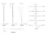
- FIG. 4 is a diagram of various aberrations when focusing on infinity in the wide-angle end state of the variable magnification optical system according to the first example.
- FIG. 3 is a diagram of various aberrations when focusing on infinity in the telephoto end state of the variable power optical system according to the first example.
- FIG. 7 is a lens configuration diagram in a wide-angle end state of a variable magnification optical system according to a second embodiment.
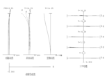
- FIG. 7 is a diagram of various aberrations when focusing on infinity in the wide-angle end state of the variable magnification optical system according to the second example.
- FIG. 4 is a diagram of various aberrations when focusing on infinity in the wide-angle end state of the variable magnification optical system according to the first example.
- FIG. 3 is a diagram of various aberrations when focusing on infinity in the telephoto end
- FIG. 7 is a diagram of various aberrations when focusing on infinity in the telephoto end state of the variable power optical system according to the second example.
- FIG. 7 is a lens configuration diagram in a wide-angle end state of a variable power optical system according to a third example.
- FIG. 7 is a diagram of various aberrations when focusing on infinity in the wide-angle end state of the variable magnification optical system according to the third example.
- FIG. 7 is a diagram of various aberrations when focusing on infinity in the telephoto end state of the variable magnification optical system according to the third example.
- FIG. 7 is a lens configuration diagram in a wide-angle end state of a variable magnification optical system according to a fourth example.
- FIG. 7 is a diagram of various aberrations when focusing on infinity in the wide-angle end state of the variable magnification optical system according to the fourth example.
- FIG. 7 is a diagram of various aberrations when focusing on infinity in the telephoto end state of the variable magnification optical system according to the fourth example.
- FIG. 7 is a lens configuration diagram in a wide-angle end state of a variable magnification optical system according to a fifth embodiment.
- FIG. 7 is a diagram of various aberrations when focusing on infinity in the wide-angle end state of the variable magnification optical system according to the fifth example.
- FIG. 7 is a diagram of various aberrations when focusing on infinity in the telephoto end state of the variable magnification optical system according to the fifth example.
- FIG. 7 is a lens configuration diagram in a wide-angle end state of a variable magnification optical system according to a sixth embodiment.
- FIG. 7 is a diagram of various aberrations when focusing on infinity in the wide-angle end state of the variable magnification optical system according to the sixth embodiment.
- FIG. 7 is a diagram of various aberrations when focusing on infinity in the telephoto end state of the variable power optical system according to the sixth embodiment.
- 1 is a diagram showing the configuration of a camera equipped with a variable magnification optical system according to each embodiment.
- 3 is a flowchart showing a method for manufacturing a variable magnification optical system according to the present invention.
- this camera 1 includes a main body 2 and a photographic lens 3 attached to the main body 2.
- the main body 2 includes an image sensor 4, a main body control section (not shown) that controls the operation of the digital camera, and a liquid crystal screen 5.
- the photographing lens 3 includes a variable magnification optical system ZL including a plurality of lens groups, and a lens position control mechanism (not shown) that controls the position of each lens group.
- the lens position control mechanism includes a sensor that detects the position of the lens group, a motor that moves the lens group back and forth along the optical axis, a control circuit that drives the motor, and the like.
- variable magnification optical system ZL of the photographic lens 3 The light from the subject is collected by the variable magnification optical system ZL of the photographic lens 3 and reaches the image plane I of the image sensor 4.
- the light from the subject that has reached the image plane I is photoelectrically converted by the image sensor 4 and recorded in a memory (not shown) as digital image data.
- the digital image data recorded in the memory can be displayed on the liquid crystal screen 5 in response to user operations.
- this camera may be a mirrorless camera or a single-lens reflex camera with a quick return mirror.
- the variable magnification optical system ZL shown in FIG. 19 is a schematic representation of the variable magnification optical system provided in the photographic lens 3, and the lens configuration of the variable magnification optical system ZL is not limited to this configuration. do not have.
- variable magnification optical system ZL (1) as an example of the variable magnification optical system (zoom lens) ZL according to the present embodiment has negative refractive powers arranged from the object side along the optical axis.
- a first lens group having a positive refractive power a second lens group having a positive refractive power
- a third lens group having a negative refractive power a fourth lens group having a positive refractive power
- variable magnification optical system ZL satisfies the following conditional expressions (1) and (2) under the above configuration. 0.70 ⁇ (-f1)/f2 ⁇ 1.30...(1) 0.55 ⁇ f2/(-f3) ⁇ 1.20...(2)
- f1 Focal length of the first lens group
- f2 Focal length of the second lens group
- f3 Focal length of the third lens group
- variable magnification optical system ZL may be the variable power optical system ZL(2) shown in FIG. 4, the variable power optical system ZL(3) shown in FIG. 7, or the variable power optical system ZL(3) shown in FIG. ZL(4), the variable power optical system ZL(5) shown in FIG. 13, or the variable power optical system ZL(6) shown in FIG. 16 may be used.
- Conditional expression (1) is a conditional expression that defines the ratio of the focal length f1 of the first lens group to the focal length f2 of the second lens group, and defines an appropriate range.
- conditional expression (1) If the corresponding value of conditional expression (1) is less than the lower limit value, the power of the first lens group increases, making it difficult to correct spherical aberration, coma aberration, and curvature of field, which is not preferable.
- the lower limit of conditional expression (1) By setting the lower limit of conditional expression (1) to 0.75 and 0.80, the effects of this embodiment can be made more reliable.
- conditional expression (1) if the corresponding value of conditional expression (1) exceeds the upper limit, the power of the second lens group increases, making it difficult to correct spherical aberration, coma aberration, and curvature of field, which is not preferable.
- the upper limit of conditional expression (1) By setting the upper limit of conditional expression (1) to 1.25 and 1.20, the effects of this embodiment can be made more reliable.
- Conditional expression (2) is a conditional expression that defines the ratio of the focal length f2 of the second lens group to the focal length f3 of the third lens group, and defines an appropriate range.
- conditional expression (2) In the variable magnification optical system, if the corresponding value of conditional expression (2) is less than the lower limit value, the power of the second lens group increases, making it difficult to correct spherical aberration, coma aberration, and curvature of field, which is not preferable.
- the lower limit of conditional expression (2) By setting the lower limit of conditional expression (2) to 0.60 and 0.65, the effects of this embodiment can be made more reliable.
- conditional expression (2) exceeds the upper limit, the power of the third lens group increases, making it difficult to correct spherical aberration, coma aberration, and curvature of field, which is not preferable.
- the upper limit of conditional expression (2) is 1.10 and 1.00, the effects of this embodiment can be made more reliable.
- variable magnification optical system ZL In the variable magnification optical system ZL according to the present embodiment, it is preferable that the following conditional expression (3) is satisfied.
- Conditional expression (3) is a conditional expression that defines the ratio between the focal length f1 of the first lens group and the focal length f4 of the fourth lens group, and defines an appropriate range.
- conditional expression (3) If the corresponding value of conditional expression (3) is less than the lower limit value, the power of the first lens group increases, making it difficult to correct spherical aberration, coma aberration, and curvature of field, which is not preferable.
- the lower limit of conditional expression (3) By setting the lower limit of conditional expression (3) to 0.25 and 0.30, the effects of this embodiment can be made more reliable.
- conditional expression (3) exceeds the upper limit, the power of the fourth lens group increases, making it difficult to correct spherical aberration, coma aberration, and curvature of field, which is not preferable.
- the upper limit of conditional expression (3) 0.45 and 0.42, the effects of this embodiment can be made more reliable.
- variable magnification optical system ZL it is preferable that the following conditional expression (4) is satisfied.
- Conditional expression (4) is a conditional expression that defines the ratio of the focal length f3 of the third lens group to the focal length f4 of the fourth lens group, and defines an appropriate range.
- conditional expression (4) If the corresponding value of conditional expression (4) is less than the lower limit, the power of the third lens group increases, making it difficult to correct spherical aberration, coma aberration, and curvature of field, which is not preferable.
- the lower limit of conditional expression (4) By setting the lower limit of conditional expression (4) to 0.25 and 0.30, the effects of this embodiment can be made more reliable.
- conditional expression (4) if the corresponding value of conditional expression (4) exceeds the upper limit, the power of the fourth lens group increases, making it difficult to correct spherical aberration, coma aberration, and curvature of field, which is not preferable.
- the upper limit of conditional expression (4) By setting the upper limit of conditional expression (4) to 0.80 and 0.70, the effects of this embodiment can be made more reliable.
- variable magnification optical system ZL it is preferable that the following conditional expression (5) is satisfied.
- Conditional expression (5) is a conditional expression that defines the ratio of the focal length f1 of the first lens group to the focal length f3 of the third lens group, and defines an appropriate range.
- conditional expression (5) If the corresponding value of conditional expression (5) is less than the lower limit value, the power of the first lens group increases, making it difficult to correct spherical aberration, coma aberration, and curvature of field, which is not preferable.
- the lower limit of conditional expression (5) By setting the lower limit of conditional expression (5) to 0.55 and 0.60, the effects of this embodiment can be made more reliable.
- conditional expression (5) exceeds the upper limit, the power of the third lens group increases, making it difficult to correct spherical aberration, coma aberration, and curvature of field, which is not preferable.
- the upper limit of conditional expression (5) is 1.00 and 0.90, the effects of this embodiment can be made more reliable.
- variable magnification optical system ZL it is preferable that the following conditional expression (6) is satisfied.
- Conditional expression (6) is a conditional expression that defines the ratio between the focal length f2 of the second lens group and the focal length f4 of the fourth lens group, and defines an appropriate range.
- conditional expression (6) If the corresponding value of conditional expression (6) is less than the lower limit value, the power of the second lens group increases, making it difficult to correct spherical aberration, coma aberration, and curvature of field, which is not preferable.
- the lower limit of conditional expression (6) By setting the lower limit of conditional expression (6) to 0.25 and 0.30, the effects of this embodiment can be made more reliable.
- conditional expression (6) exceeds the upper limit, the power of the fourth lens group increases, making it difficult to correct spherical aberration, coma aberration, and curvature of field, which is not preferable.
- the upper limit of conditional expression (6) 0.60 and 0.50, the effects of this embodiment can be made more reliable.
- variable magnification optical system ZL it is preferable that the following conditional expression (7) is satisfied.
- fw Focal length of the variable power optical system in the wide-angle end state
- TLw Total length of the variable power optical system in the wide-angle end state
- Conditional expression (7) defines the ratio of the focal length fw of the variable magnification optical system in the wide-angle end state to the total length TLw of the variable magnification optical system ZL in the wide-angle end state, and determines an appropriate range. This is a conditional expression for specifying. By satisfying conditional expression (7) in the variable magnification optical system ZL, it is possible to realize a variable magnification optical system having high optical performance while realizing miniaturization.
- conditional expression (7) If the corresponding value of conditional expression (7) is below the lower limit, it becomes difficult to realize a variable magnification optical system that has good optical performance while realizing miniaturization.
- the lower limit of conditional expression (7) By setting the lower limit of conditional expression (7) to 0.125 and 0.130, the effects of this embodiment can be made more reliable.
- conditional expression (7) If the corresponding value of conditional expression (7) exceeds the upper limit, it becomes difficult to realize a variable magnification optical system that has good optical performance while realizing miniaturization.
- the upper limits of conditional expression (7) By setting the upper limits of conditional expression (7) to 0.185 and 0.180, the effects of this embodiment can be made more reliable.
- variable magnification optical system ZL it is preferable that the following conditional expression (8) is satisfied.
- ft Focal length of the variable power optical system in the telephoto end state
- TLt Total length of the variable power optical system in the telephoto end state
- Conditional expression (8) defines the ratio of the focal length ft of the variable power optical system in the telephoto end state to the total length TLt of the variable power optical system ZL in the telephoto end state, and determines an appropriate range. This is a conditional expression for specifying.
- conditional expression (8) If the corresponding value of conditional expression (8) is below the lower limit, it becomes difficult to realize a variable magnification optical system that has good optical performance while realizing miniaturization.
- the lower limit of conditional expression (8) By setting the lower limit of conditional expression (8) to 0.25 and 0.30, the effects of this embodiment can be made more reliable.
- conditional expression (8) If the corresponding value of conditional expression (8) exceeds the upper limit, it becomes difficult to realize a variable magnification optical system that has good optical performance while realizing miniaturization.
- the upper limits of conditional expression (8) By setting the upper limits of conditional expression (8) to 0.45 and 0.40, the effects of this embodiment can be made more reliable.
- variable magnification optical system ZL In the variable magnification optical system ZL according to the present embodiment, it is preferable that the following conditional expression (9) is satisfied.
- Mv2 Amount of movement of the second lens group when changing the magnification from the wide-angle end state to the telephoto end state
- Conditional expression (9) defines the ratio of the movement amount Mv2 of the second lens group to the focal length f2 of the second lens group when changing power from the wide-angle end state to the telephoto end state, and defines an appropriate range. This is a conditional expression for By satisfying conditional expression (9) in the variable magnification optical system ZL, it is possible to realize a variable magnification optical system having good optical performance while realizing miniaturization.
- conditional expression (9) If the corresponding value of conditional expression (9) is below the lower limit, it becomes difficult to realize a variable magnification optical system that has good optical performance while realizing miniaturization.
- the lower limit of conditional expression (9) By setting the lower limit of conditional expression (9) to 0.75 and 0.80, the effects of this embodiment can be made more reliable.
- conditional expression (9) exceeds the upper limit, it becomes difficult to correct spherical aberration, coma aberration, and field curvature, which is not preferable.
- the upper limit of conditional expression (9) is 1.25 and 1.20, the effects of this embodiment can be made more reliable.
- variable magnification optical system ZL In the variable magnification optical system ZL according to the present embodiment, it is preferable that the following conditional expression (10) is satisfied.
- Mv3 Amount of movement of the third lens group when changing the magnification from the wide-angle end state to the telephoto end state
- Conditional expression (10) defines the ratio of the movement amount Mv3 of the third lens group to the focal length f3 of the third lens group when changing the magnification from the wide-angle end state to the telephoto end state, and defines an appropriate range. This is a conditional expression for When changing the magnification from the wide-angle end state to the telephoto end state, the third lens group moves toward the object side, and at this time, the variable power optical system ZL satisfies conditional expression (10), thereby realizing miniaturization. At the same time, it is possible to realize a variable power optical system having good optical performance.
- conditional expression (10) If the corresponding value of conditional expression (10) is below the lower limit, it becomes difficult to achieve good optical performance while realizing miniaturization. In order to ensure the effect of conditional expression (10), it is more preferable to set the lower limit to 0.37 or 0.38.
- conditional expression (10) exceeds the upper limit, the power of the third lens group increases, making it difficult to correct spherical aberration, coma aberration, and curvature of field, which is not preferable.
- the amount of movement Mv3 of the third lens group during zooming increases, making it difficult to downsize the optical system.
- variable magnification optical system has a diaphragm disposed within a second lens group, and the second lens group has an anti-vibration lens group disposed closer to the image plane than the diaphragm.
- variable magnification optical system ZL In the variable magnification optical system ZL according to the present embodiment, it is preferable that the following conditional expression (11) is satisfied.
- Conditional expression (11) is a conditional expression that defines the ratio of the focal length fvr of the anti-shake lens group to the focal length f2 of the second lens group, and defines an appropriate range.
- conditional expression (11) If the corresponding value of conditional expression (11) is less than the lower limit, the power of the anti-vibration lens group increases, making it difficult to correct spherical aberration, coma aberration, and curvature of field, which is not preferable.
- the lower limit of conditional expression (11) By setting the lower limit of conditional expression (11) to 1.30 and 1.40, the effects of this embodiment can be made more reliable.
- conditional expression (11) exceeds the upper limit, the power of the second lens group increases, making it difficult to correct spherical aberration, coma aberration, and curvature of field, which is not preferable.
- the upper limit of conditional expression (11) is 2.10 and 2.00, the effects of this embodiment can be made more reliable.
- variable magnification optical system ZL In the variable magnification optical system ZL according to the present embodiment, it is preferable that the following conditional expression (12) is satisfied.
- Mv2 Amount of movement of the second lens group when changing power from the wide-angle end state to the telephoto end state
- Mv3 Amount of movement of the third lens group when changing power from the wide-angle end state to the telephoto end state
- Conditional expression (12) is a conditional expression for defining the ratio of the moving amount Mv2 of the second lens group and the moving amount Mv3 of the third lens group during zooming, and defining an appropriate range.
- conditional expression (12) If the corresponding value of conditional expression (12) is less than the lower limit value, the movement amount Mv2 of the second lens group during zooming becomes small, making it difficult to correct spherical aberration, coma aberration, and curvature of field, which is not preferable. On the other hand, the amount of movement Mv3 of the third lens group increases, making it difficult to achieve miniaturization. In order to ensure the effect of conditional expression (12), it is more preferable to set the lower limit to 1.10 or 1.20.
- conditional expression (12) exceeds the upper limit, the amount of movement Mv3 of the third lens group during zooming becomes small, making it difficult to correct spherical aberration, coma aberration, and curvature of field, which is preferable. do not have.
- the amount of movement Mv2 of the second lens group increases, making it difficult to achieve miniaturization.
- variable magnification optical system it is preferable that focusing from an object at infinity to an object at a short distance is performed by moving the third lens group on the optical axis.
- focusing from an object at infinity to an object at a short distance is performed by moving the third lens group on the optical axis.
- variable power optical system when changing the power from the wide-angle end state to the telephoto end state, the second lens group and the third lens group move toward the object side, and the first lens group and the second lens group It is preferable that the distance between the third lens group and the fourth lens group increases. As a result, it is possible to realize a variable power optical system that has good optical performance with less movement of the center of gravity when changing power from the wide-angle end state to the telephoto end state.
- variable magnification optical system it is preferable that the fourth lens group is fixed to the image plane during variable magnification.
- the fourth lens group is fixed to the image plane, so that the entire length of the zooming optical system can be changed without changing. It is possible to realize a variable magnification optical system that can perform magnification and has good optical performance with little movement of the center of gravity.
- variable magnification optical system ZL In the variable magnification optical system ZL according to the present embodiment, it is preferable that the following conditional expression (13) is satisfied.
- Mv2 Amount of movement of the second lens group during zooming from the wide-angle end state to the telephoto end state
- TL Total length of the zooming optical system
- Conditional expression (13) is a conditional expression that defines the ratio between the movement amount Mv2 of the second lens group during zooming and the total length TL of the zooming optical system, and defines an appropriate range.
- the total length TL of the variable power optical system may be the total length (TLw) of the variable power optical system in the wide-angle end state, or the total length (TLt) of the variable power optical system in the telephoto end state.
- variable magnification optical system ZL In the variable magnification optical system ZL according to the present embodiment, it is preferable that the following conditional expression (14) is satisfied.
- Mv3 Amount of movement of the third lens group during zooming from the wide-angle end state to the telephoto end state TL: Total length of the zooming optical system
- Conditional expression (14) is a conditional expression that defines the ratio between the movement amount Mv3 of the third lens group during zooming and the total length TL of the zooming optical system, and defines an appropriate range.
- the total length TL of the variable power optical system may be the total length (TLw) of the variable power optical system in the wide-angle end state, or the total length (TLt) of the variable power optical system in the telephoto end state.
- variable magnification optical system ZL having the above-described configuration
- a first lens group having a negative refractive power, a second lens group having a positive refractive power, a third lens group having a negative refractive power, and a positive refractive power is arranged (step ST10), and during zooming, the first lens group is fixed to the image plane and the distance between adjacent lens groups is changed ( Step ST20). Then, each lens is arranged within the lens barrel so that at least conditional expressions (1) and (2) are satisfied (step ST30). According to such a manufacturing method, it is possible to obtain a variable power optical system ZL that is small and has good optical performance.
- FIG. 1 shows the configuration and refractive power distribution of the variable magnification optical system ZL ⁇ ZL(1) to ZL(6) ⁇ according to the first to sixth embodiments.
- FIG. The first to sixth embodiments are examples corresponding to this embodiment, and each figure shows a lens group that moves during zooming from the wide-angle end state (W) to the telephoto end state (T). The direction of movement along the optical axis is indicated by an arrow. Furthermore, the lens group that moves when focusing on a short distance object from infinity is referred to as a focusing lens group GF, and the moving direction is indicated by an arrow together with the word "focus".
- the second lens group constitutes an anti-vibration lens group GVR that can move in a direction perpendicular to the optical axis, and corrects displacement of the imaging position (image blur on the image plane I) due to camera shake, etc. do.
- the direction in which the anti-shake lens group moves when correcting image blur is indicated by an arrow along with the word "anti-shake.”
- each lens group is represented by a combination of a symbol G and a number
- each lens is represented by a combination of a symbol L and a number.
- lens groups and the like are expressed using combinations of codes and numbers independently for each embodiment. Therefore, even if the same combination of symbols and numbers is used between the embodiments, it does not mean that they have the same configuration.
- the sign (+) or (-) attached to each lens group symbol indicates the refractive power of each lens group, and this is the same in all the examples below.
- Tables 1 to 6 are shown below, of which Table 1 is the first example, Table 2 is the second example, Table 3 is the third example, Table 4 is the fourth example, and Table 5 is the fifth example.
- Table 6 is a table showing each specification data in the sixth example.
- f is the focal length of the entire optical system
- FNO is the F number
- ⁇ is the half angle of view (in degrees (degrees))
- Y is the image height.
- TL indicates the total length of the optical system. Specifically, it indicates the distance obtained by adding BF to the distance from the frontmost lens surface to the final lens surface on the optical axis when focusing on infinity, and BF is the distance when focusing on infinity. The air equivalent distance (back focus) from the final lens surface to the image plane I on the optical axis is shown. Note that these values are shown for each zooming state: wide-angle end (wide), intermediate focal length (middle), and telephoto end (tele). Further, in the [Overall specifications] table, fvr indicates the focal length of the anti-vibration lens group GVR.
- the surface number indicates the order of the optical surfaces from the object side along the direction of propagation of the light ray
- R is the radius of curvature of each optical surface (the surface whose center of curvature is located on the image side).
- D is the distance between each optical surface and the next optical surface (or image surface) on the optical axis
- nd is the refractive index of the material of the optical member with respect to the d-line.
- the radius of curvature " ⁇ " indicates a plane or an aperture
- (diaphragm S) indicates an aperture diaphragm.
- the description of the refractive index nd 1.00000 of air is omitted.
- the [Lens Group Data] table shows the focal length of each lens group.
- the [Variable spacing data] table shows the surface spacing for surface numbers for which the surface spacing is "variable” in the table showing [Lens specifications].
- the surface spacing in each zooming state at the wide-angle end (wide), intermediate focal length (middle), and telephoto end (tele) is shown when focusing on infinity and short distances, respectively.
- f indicates the focal length of the entire optical system.
- the table of [Values corresponding to conditional expressions] shows the values corresponding to each conditional expression.
- the focal length f, radius of curvature R, surface spacing D, and other lengths are generally expressed in mm unless otherwise specified, but the optical system is proportionally enlarged. Alternatively, even if the optical performance is proportionally reduced, the same optical performance can be obtained, so the present invention is not limited to this.
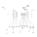
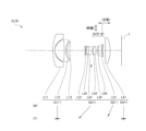
- FIG. 1 is a lens configuration diagram in a wide-angle end state of a variable magnification optical system ZL (ZL(1)) according to a first embodiment.
- the variable magnification optical system ZL(1) according to the first embodiment includes a first lens group G1 having a negative refractive power and a second lens group having a positive refractive power, which are arranged in order from the object side along the optical axis. It has a lens group G2, a third lens group G3 having a negative refractive power, and a fourth lens group G4 having a positive refractive power.
- the distance between the first lens group G1 and the second lens group G2 decreases, and the distance between the third lens group G3 and the fourth lens group G4 decreases.
- the second lens group G2 and the third lens group G3 move their optical axes on different trajectories so that the optical axis increases. More specifically, during zooming, the second lens group G2 monotonically moves toward the object side along the optical axis, the third lens group G3 monotonically moves toward the object side along the optical axis, and the first lens group G2 monotonically moves toward the object side along the optical axis.
- Group G1 and fourth lens group G4 are fixed.
- the first lens group G1 includes a meniscus-shaped positive lens L11 with a convex surface facing the object side, a meniscus-shaped negative lens L12 with a convex surface facing the object side, and a biconcave lens arranged in order from the object side along the optical axis. It has a negative lens L13 having a negative shape, and a positive lens L14 having a meniscus shape with a convex surface facing the object side.
- the second lens group G2 includes a biconvex positive lens L21, a meniscus positive lens L22 with its convex surface facing the object side, and a biconcave negative lens arranged in order from the object side along the optical axis.
- the positive lens L24 and the negative lens L25 are cemented together to form a cemented lens.
- the third lens group G3 includes a biconcave negative lens L31.
- the fourth lens group G4 is composed of a positive lens L41 with a convex surface facing the image plane side.
- An image plane I is arranged on the image side of the fourth lens group.
- the aperture stop S whose purpose is to adjust the amount of light, is placed in the second lens group, and moves on the same trajectory as the second lens group G2 during zooming from the wide-angle end state to the telephoto end state. do.
- the lenses disposed closer to the image plane than the aperture stop S in the second lens group G2 constitute an anti-vibration lens group GVR that can move in a direction perpendicular to the optical axis, so that displacement of the imaging position due to camera shake, etc. (image blur on image plane I) is corrected.
- the cemented lens of the positive lens L24 and the negative lens L25 in the second lens group G2 constitutes the anti-vibration lens group GVR.
- the third lens group G3 corresponds to the focusing lens group GF that moves along the optical axis.
- the focusing lens group GF moves toward the image plane along the optical axis.
- the 19th lens surface is formed into an aspherical shape.
- FIGS. 2 and 3 are diagrams of various aberrations of the variable magnification optical system ZL(1) according to the first example.
- FNO indicates the F number
- Y indicates the image height.
- the solid line indicates the sagittal image plane
- the broken line indicates the meridional image plane.
- meridional coma is shown. The above description of the aberration diagrams is the same for other embodiments.
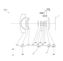
- FIG. 4 is a lens configuration diagram in the wide-angle end state of the variable magnification optical system ZL (ZL(2)) according to the second embodiment.
- the variable magnification optical system ZL(2) according to the second embodiment includes a first lens group G1 having a negative refractive power and a second lens group having a positive refractive power, which are arranged in order from the object side along the optical axis. It has a lens group G2, a third lens group G3 having a negative refractive power, and a fourth lens group G4 having a positive refractive power.
- the distance between the first lens group G1 and the second lens group G2 decreases, and the distance between the third lens group G3 and the fourth lens group G4 decreases.
- the second lens group G2 and the third lens group G3 move their optical axes on different trajectories so that the optical axis increases. More specifically, during zooming, the second lens group G2 monotonically moves toward the object side along the optical axis, the third lens group G3 monotonically moves toward the object side along the optical axis, and the first lens group G2 monotonically moves toward the object side along the optical axis.
- Group G1 and fourth lens group G4 are fixed.
- the first lens group G1 includes a meniscus-shaped positive lens L11 with a convex surface facing the object side, a meniscus-shaped negative lens L12 with a convex surface facing the object side, and a biconcave lens arranged in order from the object side along the optical axis. It has a negative lens L13 having a negative shape, and a positive lens L14 having a meniscus shape with a convex surface facing the object side.
- the second lens group G2 includes a biconvex positive lens L21, a meniscus positive lens L22 with a convex surface facing the object side, an aperture stop S, and an object side, which are arranged in order from the object side along the optical axis.
- a meniscus-shaped negative lens L23 with a convex surface facing , a biconvex positive lens L24, a biconvex positive lens L25, a biconcave negative lens L26, and a biconvex positive lens L27. has and is constituted.
- the negative lens L23 and the positive lens L24 are cemented together to form a cemented lens.
- the positive lens L25 and the negative lens L26 are cemented together to form a cemented lens.
- the third lens group G3 is composed of a biconcave negative lens L31.
- the fourth lens group G4 is composed of a positive lens L41 with a convex surface facing the image plane side.
- An image plane I is arranged on the image side of the fourth lens group.
- the aperture stop S whose purpose is to adjust the amount of light, is placed in the second lens group, and moves on the same trajectory as the second lens group G2 during zooming from the wide-angle end state to the telephoto end state. do.
- the lenses disposed closer to the image plane than the aperture stop S in the second lens group G2 constitute an anti-vibration lens group GVR that can move in a direction perpendicular to the optical axis, so that displacement of the imaging position due to camera shake, etc. (image blur on image plane I) is corrected.
- the cemented lens of the positive lens L25 and the negative lens L26 and the positive lens L27 constitute the anti-vibration lens group GVR.
- the lens group G3 corresponds to a focusing lens group GF that moves along the optical axis. When focusing from an object at infinity to an object at a short distance, the focusing lens group GF moves toward the image plane along the optical axis.
- Table 2 below shows each specification in the second example. Further, in the second embodiment, the 23rd lens surface is formed into an aspherical shape.
- FIG. 7 is a lens configuration diagram in the wide-angle end state of the variable magnification optical system ZL (ZL(3)) according to the third embodiment.
- the variable magnification optical system ZL(3) according to the third embodiment includes a first lens group G1 having a negative refractive power and a second lens group having a positive refractive power, which are arranged in order from the object side along the optical axis. It has a lens group G2, a third lens group G3 having a negative refractive power, and a fourth lens group G4 having a positive refractive power.
- the distance between the first lens group G1 and the second lens group G2 decreases, and the distance between the third lens group G3 and the fourth lens group G4 decreases.
- the second lens group G2 and the third lens group G3 move their optical axes on different trajectories so that the optical axis increases. More specifically, during zooming, the second lens group G2 monotonically moves toward the object side along the optical axis, the third lens group G3 monotonically moves toward the object side along the optical axis, and the first lens group G2 monotonically moves toward the object side along the optical axis.
- G1 and the fourth lens group G4 are fixed.
- the first lens group G1 includes a meniscus-shaped first positive lens L11 with a convex surface facing the object side and a second meniscus-shaped negative lens L12 with a convex surface facing the object side, which are arranged in order from the object side along the optical axis. , a biconcave third negative lens L13, and a meniscus fourth positive lens L14 with a convex surface facing the object side.
- the second lens group G2 includes a meniscus-shaped positive lens L21 with a convex surface facing the object side, which is arranged in order from the object side along the optical axis, a biconcave negative lens L22, and a biconvex positive lens L23. , an aperture stop S, a meniscus-shaped negative lens L24 with a convex surface facing the object side, a meniscus-shaped positive lens L25 with a convex surface facing the object side, and a double-convex positive lens L26. , configured.
- the negative lens L22 and the positive lens L23 are cemented together to form a cemented lens. Further, the negative lens L24 and the positive lens L25 are cemented together to form a cemented lens.
- the third lens group G3 includes a biconcave negative lens L31.
- the fourth lens group G4 is composed of a positive lens L41 with a convex surface facing the image plane side.
- An image plane I is arranged on the image side of the fourth lens group.
- the aperture stop S whose purpose is to adjust the amount of light, is placed in the second lens group, and moves on the same trajectory as the second lens group G2 during zooming from the wide-angle end state to the telephoto end state. do.
- the lenses disposed closer to the image plane than the aperture stop S in the second lens group G2 constitute an anti-vibration lens group GVR that can move in a direction perpendicular to the optical axis, so that displacement of the imaging position due to camera shake, etc. (image blur on image plane I) is corrected.
- the cemented lens in which the negative lens L24 and the positive lens L25 in the second lens group G2 are cemented together, and the biconvex positive lens L26 constitute the anti-vibration lens group GVR.
- the third lens group G3 corresponds to the focusing lens group GF that moves along the optical axis.
- the focusing lens group GF moves toward the image plane along the optical axis.
- the 21st lens surface is formed into an aspherical shape.
- FIG. 10 is a lens configuration diagram in the wide-angle end state of the variable magnification optical system ZL (ZL(4)) according to the fourth embodiment.
- the variable magnification optical system ZL(4) according to the fourth embodiment includes a first lens group G1 having a negative refractive power and a second lens group having a positive refractive power, which are arranged in order from the object side along the optical axis.
- a lens group G2, a third lens group G3 having a negative refractive power, and a fourth lens group G4 having a positive refractive power are configured.
- the distance between the first lens group G1 and the second lens group G2 decreases, and the distance between the third lens group G3 and the fourth lens group G4 decreases.
- the second lens group G2 and the third lens group G3 move their optical axes on different trajectories so that the optical axis increases. More specifically, during zooming, the second lens group G2 monotonically moves toward the object side along the optical axis, the third lens group G3 monotonically moves toward the object side along the optical axis, and the first lens group G2 monotonically moves toward the object side along the optical axis.
- Group G1 and fourth lens group G4 are fixed.
- the first lens group G1 includes a meniscus-shaped positive lens L11 with a convex surface facing the object side, a meniscus-shaped negative lens L12 with a convex surface facing the object side, and a biconcave lens arranged in order from the object side along the optical axis. It has a negative lens L13 having a negative shape, and a positive lens L14 having a meniscus shape with a convex surface facing the object side.
- the second lens group G2 includes a biconvex positive lens L21, a meniscus positive lens L22 with a convex surface facing the object side, and a meniscus positive lens L22 with a convex surface facing the image side, which are arranged in order from the object side along the optical axis.
- the positive lens L24 and the negative lens L25 are cemented together to form a cemented lens.
- the third lens group G3 includes a biconcave negative lens L31.
- the fourth lens group G4 is composed of a positive lens L41 with a convex surface facing the image plane side.
- An image plane I is arranged on the image side of the fourth lens group.
- the aperture stop S whose purpose is to adjust the amount of light, is placed in the second lens group, and moves on the same trajectory as the second lens group G2 during zooming from the wide-angle end state to the telephoto end state. do.
- the lenses disposed closer to the image plane than the aperture stop S in the second lens group G2 constitute an anti-vibration lens group GVR that can move in a direction perpendicular to the optical axis, so that displacement of the imaging position due to camera shake, etc. (image blur on image plane I) is corrected.
- a cemented lens in which the positive lens L24 and the negative lens L25 in the second lens group G2 are cemented together constitutes the anti-vibration lens group GVR.
- the third lens group G3 corresponds to the focusing lens group GF that moves along the optical axis.
- the focusing lens group GF moves toward the image plane along the optical axis.
- the 19th lens surface is formed into an aspherical shape.
- FIG. 13 is a lens configuration diagram in the wide-angle end state of the variable magnification optical system ZL (ZL(5)) according to the fifth embodiment.
- the variable magnification optical system ZL(5) according to the fifth embodiment includes a first lens group G1 having a negative refractive power and a second lens group having a positive refractive power, which are arranged in order from the object side along the optical axis. It has a lens group G2, a third lens group G3 having a negative refractive power, and a fourth lens group G4 having a positive refractive power.
- the distance between the first lens group G1 and the second lens group G2 decreases, and the distance between the third lens group G3 and the fourth lens group G4 decreases.
- the second lens group G2 and the third lens group G3 move their optical axes on different trajectories so that the optical axis increases. More specifically, during zooming, the second lens group G2 monotonically moves toward the object side along the optical axis, the third lens group G3 monotonically moves toward the object side along the optical axis, and the first lens group G2 monotonically moves toward the object side along the optical axis.
- Group G1 and fourth lens group G4 are fixed.
- the first lens group G1 includes a meniscus-shaped negative lens L11 with a convex surface facing the object side, a meniscus-shaped negative lens L12 with a convex surface facing the object side, which are arranged in order from the object side along the optical axis. It has a meniscus-shaped positive lens L13 with a convex surface facing the side.
- the negative lens L11 is a hybrid lens configured by providing a resin layer on the image plane side of a glass lens body.
- the image plane side surface of the resin layer is an aspherical surface
- the negative lens L11 is a composite aspherical lens.
- surface number 1 is the object-side surface of the lens body
- surface number 2 is the image-side surface of the lens body
- the object-shaped surface of the resin layer (the surface where the two join)
- the surface indicates the surface of the resin layer on the image plane side.
- the second lens group G2 includes a biconvex positive lens L21, a meniscus negative lens L22 with a convex surface facing the object side, and a biconvex positive lens L23, which are arranged in order from the object side along the optical axis. , an aperture stop S, a meniscus negative lens L24 with a convex surface facing the object side, a biconvex positive lens L25, and a biconvex positive lens L26.
- the negative lens L22 and the positive lens L23 are cemented together to form a cemented lens. Further, the negative lens L24 and the positive lens L25 are cemented together to form a cemented lens.
- the third lens group G3 is composed of a meniscus-shaped negative lens L31 with a convex surface facing the object side.
- the fourth lens group G4 is composed of a positive lens L41 with a convex surface facing the image plane side.
- An image plane I is arranged on the image side of the fourth lens group.
- the aperture stop S whose purpose is to adjust the amount of light, is placed in the second lens group, and moves on the same trajectory as the second lens group G2 during zooming from the wide-angle end state to the telephoto end state. do.
- the lenses disposed closer to the image plane than the aperture stop S in the second lens group G2 constitute an anti-vibration lens group GVR that can move in a direction perpendicular to the optical axis, so that displacement of the imaging position due to camera shake, etc. (image blur on image plane I) is corrected.
- the cemented lens in which the negative lens L24 and the positive lens L25 in the second lens group G2 are cemented, and the positive lens L26 constitute the anti-vibration lens group GVR.
- the third lens group G3 corresponds to the focusing lens group GF that moves along the optical axis.
- the focusing lens group GF moves toward the image plane along the optical axis.
- each of the third, eighth, and nineteenth lens surfaces is formed into an aspherical shape.
- FIG. 18 is a lens configuration diagram in the wide-angle end state of the variable magnification optical system ZL (ZL(6)) according to the sixth embodiment.
- the variable magnification optical system ZL(6) according to the sixth embodiment includes a first lens group G1 having a negative refractive power and a second lens group having a positive refractive power, which are arranged in order from the object side along the optical axis. It has a lens group G2, a third lens group G3 having a negative refractive power, and a fourth lens group G4 having a positive refractive power.
- the distance between the first lens group G1 and the second lens group G2 decreases, and the distance between the third lens group G3 and the fourth lens group G4 decreases.
- the second lens group G2 and the third lens group G3 move their optical axes on different trajectories so that the optical axis increases. More specifically, during zooming, the second lens group G2 monotonically moves toward the object side along the optical axis, the third lens group G3 monotonically moves toward the object side along the optical axis, and the first lens group G2 monotonically moves toward the object side along the optical axis.
- Group G1 and fourth lens group G4 are fixed.
- the first lens group G1 includes a meniscus-shaped negative lens L11 with a convex surface facing the object side, a biconcave negative lens L12, and a negative lens L12 with a biconcave surface, which are arranged in order from the object side along the optical axis. It has a meniscus-shaped positive lens L13, and is configured.
- the negative lens L11 is a hybrid lens configured by providing a resin layer on the image plane side of a glass lens body.
- the image plane side surface of the resin layer is an aspherical surface
- the negative lens L11 is a composite aspherical lens.
- surface number 1 is the object-side surface of the lens body
- surface number 2 is the image-side surface of the lens body
- the object-shaped surface of the resin layer (the surface where the two join)
- the surface indicates the surface of the resin layer on the image plane side.
- the second lens group G2 includes a meniscus-shaped positive lens L21 with a convex surface facing the object side, a meniscus-shaped negative lens L22 with a convex surface facing the object side, which are arranged in order from the object side along the optical axis.
- the negative lens L22 and the positive lens L23 are cemented together to form a cemented lens. Further, the negative lens L24 and the positive lens L25 are cemented together to form a cemented lens.
- the third lens group G3 is composed of a biconcave negative lens L31.
- the fourth lens group G4 is composed of a positive lens L41 with a convex surface facing the image plane side.
- An image plane I is arranged on the image side of the fourth lens group.
- the negative lens L31 is a hybrid lens configured by providing a resin layer on the image plane side of a glass lens body.
- the image plane side surface of the resin layer is an aspherical surface
- the negative lens L31 is a composite aspherical lens.
- surface number 19 is the object-side surface of the lens body
- surface number 20 is the image-side surface of the lens body
- the object-shaped surface of the resin layer (the surface where the two join)
- the surface. Number 21 indicates the surface of the resin layer on the image plane side.
- the aperture stop S whose purpose is to adjust the amount of light, is placed in the second lens group, and moves on the same trajectory as the second lens group G2 during zooming from the wide-angle end state to the telephoto end state. do.
- the lenses disposed closer to the image plane than the aperture stop S in the second lens group G2 constitute an anti-vibration lens group GVR that can move in a direction perpendicular to the optical axis, so that displacement of the imaging position due to camera shake, etc. (image blur on image plane I) is corrected.
- the cemented lens in which the negative lens L24 and the positive lens L25 in the second lens group G2 are cemented, and the negative lens L26 constitute the anti-vibration lens group GVR.
- the third lens group G3 corresponds to the focusing lens group GF that moves along the optical axis.
- the focusing lens group GF moves toward the image plane along the optical axis.
- each of the third, seventeenth, eighteenth, and twenty-first lens surfaces is formed into an aspherical shape.
- Conditional expression (1) 0.70 ⁇ (-f1)/f2 ⁇ 1.30 Conditional expression (2) 0.55 ⁇ f2/(-f3) ⁇ 1.20 Conditional expression (3) 0.20 ⁇ (-f1)/f4 ⁇ 0.50 Conditional expression (4) 0.20 ⁇ (-f3)/f4 ⁇ 0.90 Conditional expression (5) 0.50 ⁇ f1/f3 ⁇ 1.10 Conditional expression (6) 0.20 ⁇ f2/f4 ⁇ 0.70 Conditional expression (7) 0.120 ⁇ fw/TLw ⁇ 0.190 Conditional expression (8) 0.20 ⁇ ft/TLt ⁇ 0.50 Conditional expression (9) 0.70 ⁇ Mv2/f2 ⁇ 1.30 Conditional expression (10) 0.36 ⁇ Mv3/(-f3) ⁇ 0.80 Conditional expression (11) 1.20 ⁇ fvr/f2 ⁇ 2.20 Conditional expression (1) 0.70 ⁇ (-f1)/f2 ⁇ 1.30 Conditional expression (2) 0.55 ⁇ f2/(-f3) ⁇ 1.20 Conditional expression (3) 0.20
- a four-group configuration is shown as a variable magnification optical system, but it is also applicable to other group configurations such as five groups. Further, a configuration in which a lens or a lens group is added to the closest to the object side, or a configuration in which a lens or a lens group is added to the closest to the image side may be used. Further, the lens group refers to a portion having at least one lens separated by an air gap that changes when changing the magnification.
- a focusing lens group may be used that focuses from an object at infinity to an object at a short distance by moving one or more lens groups, or a partial lens group in the optical axis direction.
- This focusing lens group can also be applied to autofocus, and is also suitable for driving a motor (using an ultrasonic motor or the like) for autofocus.
- variable power optical system of each embodiment not only a part of the lenses in the second lens group but also a lens group or a partial lens group is moved so as to have a component in a direction perpendicular to the optical axis, or the optical axis is It may also be used as an anti-vibration lens group that rotates (swings) in the in-plane direction to correct image blur caused by camera shake.
- the lens surface may be formed as a spherical surface, a flat surface, or an aspherical surface. It is preferable that the lens surface is spherical or flat because it facilitates lens processing and assembly adjustment and prevents deterioration of optical performance due to errors in processing and assembly adjustment. Further, even if the image plane shifts, there is little deterioration in depiction performance, which is preferable.
- the aspherical surface can be an aspherical surface made by grinding, a glass molded aspherical surface made by molding glass into an aspherical shape, or a composite aspherical surface made by molding resin into an aspherical shape on the glass surface. Either is fine.
- the lens surface may be a diffractive surface, and the lens may be a gradient index lens (GRIN lens) or a plastic lens.
- the aperture stop is placed within the second lens group, the role of the aperture stop may be substituted by the frame of the lens without providing a member serving as the aperture stop.
- Each lens surface may be coated with an antireflection film that has high transmittance in a wide wavelength range in order to reduce flare and ghosting and achieve high optical performance with high contrast.
- variable magnification optical system of this embodiment is used in a camera, it is not limited to this, and may be used in an optical device such as a camera with a video shooting function.
Landscapes
- Physics & Mathematics (AREA)
- General Physics & Mathematics (AREA)
- Optics & Photonics (AREA)
- Nonlinear Science (AREA)
- Lenses (AREA)
Abstract
L'invention concerne un système optique de zoom (ZL) comprenant, séquentiellement le long d'un axe optique depuis un côté objet, un premier groupe de lentilles (G1) ayant une réfringence négative, un deuxième groupe de lentilles (G2) ayant une réfringence positive, un troisième groupe de lentilles (G3) ayant une réfringence négative, et un quatrième groupe de lentilles (G4) ayant une réfringence positive, le premier groupe de lentilles (G1) étant fixé par rapport à la surface d'image et les intervalles entre les groupes de lentilles voisins changeant pour satisfaire aux expressions conditionnelles suivantes. 0,70 < (-f1) / f2 < 1,30
0,55 < f2 / (-f3) < 1,20 où
f1 : longueur focale du premier groupe de lentilles
f2 : longueur focale du deuxième groupe de lentilles
f3 : longueur focale du troisième groupe de lentilles
Applications Claiming Priority (2)
| Application Number | Priority Date | Filing Date | Title |
|---|---|---|---|
| JP2022143715 | 2022-09-09 | ||
| JP2022-143715 | 2022-09-09 |
Publications (1)
| Publication Number | Publication Date |
|---|---|
| WO2024053269A1 true WO2024053269A1 (fr) | 2024-03-14 |
Family
ID=90192352
Family Applications (1)
| Application Number | Title | Priority Date | Filing Date |
|---|---|---|---|
| PCT/JP2023/026980 WO2024053269A1 (fr) | 2022-09-09 | 2023-07-24 | Système optique de zoom, dispositif optique et procédé de fabrication d'un système optique de zoom |
Country Status (1)
| Country | Link |
|---|---|
| WO (1) | WO2024053269A1 (fr) |
Citations (9)
| Publication number | Priority date | Publication date | Assignee | Title |
|---|---|---|---|---|
| JP2007093955A (ja) * | 2005-09-28 | 2007-04-12 | Fujinon Corp | ズームレンズ |
| JP2008304777A (ja) * | 2007-06-08 | 2008-12-18 | Konica Minolta Opto Inc | 変倍光学系、撮像装置及びデジタル機器 |
| JP2010152145A (ja) * | 2008-12-25 | 2010-07-08 | Panasonic Corp | ズームレンズ系、撮像装置及びカメラ |
| JP2012027262A (ja) * | 2010-07-23 | 2012-02-09 | Olympus Imaging Corp | ズームレンズ及びそれを備えた撮像装置 |
| JP2012181350A (ja) * | 2011-03-01 | 2012-09-20 | Olympus Imaging Corp | ズームレンズ |
| JP2012230209A (ja) * | 2011-04-26 | 2012-11-22 | Olympus Imaging Corp | マクロモードを備えたズームレンズ |
| JP2013064912A (ja) * | 2011-09-20 | 2013-04-11 | Konica Minolta Advanced Layers Inc | 撮像レンズ及び撮像装置 |
| JP2015206979A (ja) * | 2014-04-23 | 2015-11-19 | Hoya株式会社 | 撮像光学系 |
| JP2019120821A (ja) * | 2018-01-09 | 2019-07-22 | キヤノン株式会社 | ズームレンズ及びそれを有する撮像装置、撮像システム |
-
2023
- 2023-07-24 WO PCT/JP2023/026980 patent/WO2024053269A1/fr unknown
Patent Citations (9)
| Publication number | Priority date | Publication date | Assignee | Title |
|---|---|---|---|---|
| JP2007093955A (ja) * | 2005-09-28 | 2007-04-12 | Fujinon Corp | ズームレンズ |
| JP2008304777A (ja) * | 2007-06-08 | 2008-12-18 | Konica Minolta Opto Inc | 変倍光学系、撮像装置及びデジタル機器 |
| JP2010152145A (ja) * | 2008-12-25 | 2010-07-08 | Panasonic Corp | ズームレンズ系、撮像装置及びカメラ |
| JP2012027262A (ja) * | 2010-07-23 | 2012-02-09 | Olympus Imaging Corp | ズームレンズ及びそれを備えた撮像装置 |
| JP2012181350A (ja) * | 2011-03-01 | 2012-09-20 | Olympus Imaging Corp | ズームレンズ |
| JP2012230209A (ja) * | 2011-04-26 | 2012-11-22 | Olympus Imaging Corp | マクロモードを備えたズームレンズ |
| JP2013064912A (ja) * | 2011-09-20 | 2013-04-11 | Konica Minolta Advanced Layers Inc | 撮像レンズ及び撮像装置 |
| JP2015206979A (ja) * | 2014-04-23 | 2015-11-19 | Hoya株式会社 | 撮像光学系 |
| JP2019120821A (ja) * | 2018-01-09 | 2019-07-22 | キヤノン株式会社 | ズームレンズ及びそれを有する撮像装置、撮像システム |
Similar Documents
| Publication | Publication Date | Title |
|---|---|---|
| EP2360504B1 (fr) | Système de lentilles de zoom, appareil optique et procédé de fabrication de lentilles de zoom | |
| US10095012B2 (en) | Zoom lens system, optical apparatus and method for manufacturing zoom lens system | |
| JP5557092B2 (ja) | ズームレンズ、光学機器、およびズームレンズの製造方法 | |
| US11714268B2 (en) | Variable magnification optical system, optical device, and method for manufacturing variable magnification optical system | |
| CN110058391B (zh) | 变倍光学系统以及光学设备 | |
| JP5333906B2 (ja) | ズームレンズおよび光学機器 | |
| EP2325681A1 (fr) | Lentille de zoom, appareil optique et procédé de fabrication de lentille de zoom | |
| JP2012163855A (ja) | ズームレンズ、光学装置、ズームレンズの製造方法 | |
| JP2012027309A (ja) | ズームレンズ、光学装置、ズームレンズの製造方法 | |
| CN107884917B (zh) | 变倍光学系统和光学装置 | |
| JP7254271B2 (ja) | 変倍光学系、光学機器 | |
| JP6507471B2 (ja) | 光学系、及び光学装置 | |
| JP5532402B2 (ja) | ズームレンズおよび光学機器 | |
| JP7218813B2 (ja) | 変倍光学系及び光学機器 | |
| JP5212813B2 (ja) | ズームレンズ、これを搭載する光学機器および製造方法 | |
| CN113302533B (zh) | 变倍光学系统以及光学设备 | |
| WO2024053269A1 (fr) | Système optique de zoom, dispositif optique et procédé de fabrication d'un système optique de zoom | |
| JP5505770B2 (ja) | ズームレンズ、光学機器 | |
| JP7364084B2 (ja) | 変倍光学系および光学機器 | |
| JP7409511B2 (ja) | 変倍光学系および光学機器 | |
| WO2024034309A1 (fr) | Système optique à grossissement variable, appareil optique et procédé de fabrication de système optique à grossissement variable | |
| JP7375970B2 (ja) | 変倍光学系およびこれを用いた光学機器 | |
| CN113495349B (zh) | 变焦镜头和摄像设备 | |
| WO2023181903A1 (fr) | Système optique à grossissement variable, dispositif optique et procédé de fabrication d'un système optique à grossissement variable | |
| JP5110128B2 (ja) | ズームレンズ、光学装置、ズームレンズの製造方法 |
Legal Events
| Date | Code | Title | Description |
|---|---|---|---|
| 121 | Ep: the epo has been informed by wipo that ep was designated in this application |
Ref document number: 23862812 Country of ref document: EP Kind code of ref document: A1 |