WO2022024196A1 - 通信システム、接続先制御方法、制御装置、及びプログラム - Google Patents
通信システム、接続先制御方法、制御装置、及びプログラム Download PDFInfo
- Publication number
- WO2022024196A1 WO2022024196A1 PCT/JP2020/028756 JP2020028756W WO2022024196A1 WO 2022024196 A1 WO2022024196 A1 WO 2022024196A1 JP 2020028756 W JP2020028756 W JP 2020028756W WO 2022024196 A1 WO2022024196 A1 WO 2022024196A1
- Authority
- WO
- WIPO (PCT)
- Prior art keywords
- terminal
- dead zone
- dead
- control device
- connection destination
- Prior art date
Links
- 238000004891 communication Methods 0.000 title claims abstract description 42
- 238000000034 method Methods 0.000 title claims description 25
- 230000005540 biological transmission Effects 0.000 claims abstract description 6
- 230000008569 process Effects 0.000 description 8
- 238000004364 calculation method Methods 0.000 description 7
- 230000006870 function Effects 0.000 description 7
- 230000006866 deterioration Effects 0.000 description 6
- 238000012545 processing Methods 0.000 description 6
- 238000010586 diagram Methods 0.000 description 5
- 238000012986 modification Methods 0.000 description 4
- 230000004048 modification Effects 0.000 description 4
- 238000005516 engineering process Methods 0.000 description 3
- 230000002093 peripheral effect Effects 0.000 description 3
- 238000005259 measurement Methods 0.000 description 2
- 230000001133 acceleration Effects 0.000 description 1
- 230000008859 change Effects 0.000 description 1
- 230000002950 deficient Effects 0.000 description 1
- 238000001514 detection method Methods 0.000 description 1
- 230000002542 deteriorative effect Effects 0.000 description 1
- 230000000694 effects Effects 0.000 description 1
- 238000012423 maintenance Methods 0.000 description 1
- 230000008685 targeting Effects 0.000 description 1
Images


Classifications
-
- H—ELECTRICITY
- H04—ELECTRIC COMMUNICATION TECHNIQUE
- H04W—WIRELESS COMMUNICATION NETWORKS
- H04W36/00—Hand-off or reselection arrangements
- H04W36/24—Reselection being triggered by specific parameters
- H04W36/32—Reselection being triggered by specific parameters by location or mobility data, e.g. speed data
- H04W36/322—Reselection being triggered by specific parameters by location or mobility data, e.g. speed data by location data
-
- H—ELECTRICITY
- H04—ELECTRIC COMMUNICATION TECHNIQUE
- H04W—WIRELESS COMMUNICATION NETWORKS
- H04W36/00—Hand-off or reselection arrangements
- H04W36/0005—Control or signalling for completing the hand-off
- H04W36/0083—Determination of parameters used for hand-off, e.g. generation or modification of neighbour cell lists
- H04W36/00835—Determination of neighbour cell lists
-
- H—ELECTRICITY
- H04—ELECTRIC COMMUNICATION TECHNIQUE
- H04W—WIRELESS COMMUNICATION NETWORKS
- H04W36/00—Hand-off or reselection arrangements
- H04W36/24—Reselection being triggered by specific parameters
- H04W36/30—Reselection being triggered by specific parameters by measured or perceived connection quality data
- H04W36/302—Reselection being triggered by specific parameters by measured or perceived connection quality data due to low signal strength
-
- H—ELECTRICITY
- H04—ELECTRIC COMMUNICATION TECHNIQUE
- H04W—WIRELESS COMMUNICATION NETWORKS
- H04W64/00—Locating users or terminals or network equipment for network management purposes, e.g. mobility management
Definitions
- the present invention relates to a technique for avoiding deterioration of communication quality and communication interruption in a wireless communication system.
- Non-Patent Document 1 Standardization of a wireless communication system called 5G (for example, Non-Patent Document 1) is being promoted in 3GPP, and 5G communication services have been started.
- L5G local 5G
- 5G has features such as ultra-high speed, ultra-low delay, and multiple simultaneous connections, and is expected to be used for various wireless access. Especially in L5G, the use of mission-critical applications is expected, and maintenance of communication quality is required more strictly. Further, since the introduction cost of L5G is higher than that of other wireless systems (wireless LAN), it is expected that the introduction will be limited to an area such as limiting the number of base stations.
- the radio wave has high straightness, and there is a possibility that an area or a dead zone where the radio wave is difficult to reach may occur due to the pillars or obstacles of the building. .. If the terminal (UE) enters an area where radio waves are difficult to reach or a dead zone, communication quality may deteriorate (including communication interruption).
- the present invention has been made in view of the above points, and an object of the present invention is to provide a technique for avoiding deterioration of communication quality caused by a terminal entering a dead zone in a wireless communication system.
- a communication system having a terminal that wirelessly communicates with a base station and a control device.
- the terminal includes a transmission unit that transmits the position information of the terminal.
- the control device is The dead zone setting section that sets the area around the dead zone as the dead zone, and the dead zone setting section.
- An information gathering unit that acquires the location information of the terminal, By comparing the position information of the terminal with the dead reserve area, it is determined whether or not the terminal exists in the dead reserve area, and when it is determined that the terminal exists in the dead reserve area, the said.
- a communication system including a connection destination control unit that executes control for switching a connection destination of a terminal is provided.
- a technology for avoiding deterioration of communication quality caused by a terminal entering a dead zone is provided.
- the "dead zone” is an area where radio waves from the base station are difficult to reach.
- the “area where radio waves are difficult to reach” is, for example, an area where only radio waves with power equal to or lower than a certain threshold can reach (including areas where radio waves do not reach at all).
- the terminal will be referred to as a UE.
- UE is an abbreviation for User Equipment.
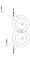
- base station 1 and base station 2 exist, and their respective radio wave reach ranges are shown as area A and area B, respectively.
- the UE 10 is connected to the base station 1.
- a shield C such as a wall exists at the position shown in the figure, and the area behind the shield C when viewed from the base station 1 is a dead zone.
- FIG. 2 shows a change in communication quality (for example, throughput in UE 10) when the UE 10 passes through a dead zone and moves to area B. As shown in FIG. 2, the throughput becomes 0 during the period when the UE 10 passes through the dead zone.
- a change in communication quality for example, throughput in UE 10
- a dead zone is set around the dead zone, and the control device 100 described later sets the dead zone of the UE 10.
- the UE 10 is made to switch the connection to another line (another base station, etc.) in advance and to perform redundancy by connecting a plurality of lines.
- FIG. 3 shows an example of the overall configuration of the communication system according to the present embodiment.
- this system has a control device 100, a carrier network 200, a carrier network 300, and an L5G operator network 400, which are connected to the Internet 500.
- the UE 10 wirelessly communicates with the base station 430 or the like of the L5G operator network 400 according to its position.
- the carrier network 200 has an LTE core network 210 and a base station 220. Although only one base station is shown in each network in FIG. 3, this is for convenience of illustration, and a large number of base stations may actually exist.
- the carrier network 300 has a 5G core network 310 and a base station 320.
- the L5G operator network 400 has an integrated SW410, an L5G core network 420, a base station 430, and a wireless LAN-AP440.
- the network may include a plurality of wireless systems such as a wireless LAN-AP and an IoT terminal.
- FIG. 3 shows, as an example, an example in which a wireless LAN-AP440 exists in the L5G operator network 400.
- the control device 100 is a device that executes the control process according to the present invention, and is a virtual server provided on the cloud or a physical server provided on the physical network.
- the placement location of the control device 100 is not limited to a specific location, but the placement location may be determined according to the control range. For example, when it is assumed that the UE 10 connected to the L5G business network 400 is controlled, the control device 100 may be installed at a location close to the L5G business network 400.
- the information from the UE 10 is transmitted to the control device 100 via the wireless system (LTE, 5G, L5G, wireless LAN, IoT terminal, etc.) of the connection destination.
- the wireless system LTE, 5G, L5G, wireless LAN, IoT terminal, etc.
- FIG. 4 An outline of the operation of the system according to the present embodiment will be described with reference to FIGS. 4 and 5.
- base station 1 and base station 2 exist, and their respective radio wave reach ranges are shown as area A and area B, respectively.
- a shield C such as a wall exists at the position shown in the drawing, and the area behind the shield C when viewed from the base station 1 is a dead zone of the base station 1.
- the base station 1 and the base station 2 may be any of the carrier network 200, 300, and the L5G operator network 500, respectively. Further, the base station 1 and the base station 2 may be wireless LAN-AP, respectively.
- the UE 10 moves from the area A through the dead zone to the area B.
- a dead zone is set around the dead zone.
- the control device 100 determines whether or not the UE 10 has entered the dead reserve area based on the position information of the UE 10.
- the control device 100 determines that the UE 10 has entered the dead space, for example, the control device 100 instructs the UE 10 to switch the line from the base station 1 to the base station 2.
- the control device 100 may instruct the UE 10 to connect to both the base station 1 and the base station 2 and use a redundant line. It should be noted that the above-mentioned line switching and instruction for using a redundant line may be given to the base station 1.
- the UE 10 can communicate with the base station 2 before entering the dead zone, so that deterioration of communication quality due to the dead zone with respect to the base station 1 can be avoided. Therefore, as shown in FIG. 5, it is possible to switch the connection destination from the base station 1 to the base station 2 without deteriorating the quality of goods.
- the control device 100 periodically collects the position information of the UE 10.
- the UE 10 is equipped with a GPS device and the position information obtained by the GPS device is transmitted from the UE 10 to the control device 100, but the method of collecting the position information is as follows. It is not limited to this method.
- a sensor provided around the UE 10 may acquire the position information of the UE 10 and transmit it to the control device 100.
- the position information of the UE 10 collected by the control device 100 is, for example, xy coordinates and latitude / longitude, but is not limited to these, and may be three-dimensional position information including the height.
- control device 100 may collect the position information of the UE 10 and the barometric pressure sensor information at the position of the UE 10 (barometric pressure at the position of the UE 10).
- the control device 100 can acquire the position in the height direction of the UE 10 from the barometric pressure sensor information.
- the position in the height direction can be used when considering the position of the UE 10 three-dimensionally, such as in a building.
- the control device 100 may collect the speed of the UE 10 and the radio wave strength from the base station in the UE 10 from the UE 10.
- the barometric pressure sensor information may be the barometric pressure sensor information provided in the UE 10 or the barometric pressure sensor information provided in the vicinity of the UE 10.
- the control device 100 holds the position information of the dead zone. As shown in FIG. 7, for example, when a dead zone is a circle with a radius R, the control device 100 desensitizes a dead zone for the dead zone from a circle having a radius R + r centered on the center of the dead zone. It is set as a donut-shaped area excluding the zone (circle with radius R). That is, the dead zone is an area centered on the center of the dead zone and having a radius R or more and r or less. “R” may be predetermined or may be dynamically determined according to the speed of the UE 10 or the like.
- the control device 100 compares the current position of the UE 10 acquired in S101 with the dead zone for the dead zone in the base station to which the UE 10 is connected, and the position of the UE 10 is in the dead zone. Whether or not (that is, whether or not the UE 10 has entered the dead zone) is determined. If it is determined that the UE 10 has entered the dead reserve area, the process proceeds to S103. In the above comparison, the control device 100 also compares the current position of the UE 10 acquired in S101 with the dead zone for the dead zone in each base station around the base station to which the UE 10 is connected. ..
- the control device 100 transmits a line switching instruction to the UE 10 (or the connection base station of the UE 10). As described above, a redundant line connection may be instructed.
- the connection destination base station for line switching (or redundant configuration) is a base station in the vicinity where the UE 10 is not located in the dead reserve area.
- the control device 100 determines that the position of the UE 10 is within the dead zone of all the surrounding base stations (all the peripheral base stations to which the UE 10 can be connected), the connected base station and all the peripheral bases concerned. Among the stations, the base station having the largest distance from the center of the dead zone corresponding to the dead zone in which the UE 10 is located is selected, and that base station is used as the connection destination of the UE 10.
- the base station selection as described above is performed. ing.
- the control is performed.
- the device 100 connects the UE 10 to the base station 2 having a large distance from the center.
- the control device 100 performs the dead zone calculation process, which is an example.
- a device other than the control device 100 may perform a dead zone calculation process, and the control device 100 may receive information on the dead zone from the device.
- a plurality of sensors 50 are arranged in the service providing area.
- the service providing area is a service providing area of the base station.
- FIG. 9 shows the service providing area of the base station 60 as an example.
- Each sensor 50 has a function of measuring reception quality and feeding back the measurement result to the control device 100.
- Each UE (UEs 10A and 10B are shown in FIG. 9) also has a function of measuring the reception quality and feeding back the measurement result to the control device 100.
- the sensor 50 and the base station 60 may be wirelessly connected or may be wiredly connected.
- each sensor 50 has a communication function with the base station similar to the UE 10, and uses a user data area or a control message by allocation from the base station 60.
- the feedback signal can be transmitted to the base station 60.
- each sensor 50 measures the reception quality (received radio wave information) and transmits it to the control device 100.
- Each UE 10 transmits its own position information and reception quality to the control device 100.
- the reception quality is, for example, one of SS-RSRP, CSI-RSRP, NR-RSSI, CSI-RSSI, SS-RSRQ, CSI-RSRQ, SS-SINR, CSI-SINR, or a combination of any one or more.
- uplink communication of the target wireless system may be used, or another access means such as a wired connection or a wireless LAN may be used.
- control device 100 grasps the position where the dead zone is detected based on the received reception quality and the position information associated with the sensor 50 of the transmission source of the reception quality.
- the control device 100 determines that the received radio wave condition at that position is good, and the reception quality is a predetermined threshold value. If it is not the above, it is determined that the received radio wave condition at that position is defective (Bad).
- the control device 100 determines that the position determined that the received radio wave condition is bad (Bad) is the position of the dead zone.
- the position is assumed to be a two-dimensional position such as xy coordinates, longitude, and latitude, but when targeting indoor facilities, etc., the height direction (z-axis direction) is added.
- the three-dimensional position may be targeted.
- the dead zone has a three-dimensional shape (for example, a sphere).
- the control device 100 determines the range of the radius R as the dead zone centering on the position where the dead zone is detected, and stores the information of the dead zone (eg, the radius and the center position of the circle) in the DB.
- R is a predetermined value. It should be noted that setting a dead zone in this way is an example.
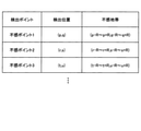
- FIG. 11 shows an example of dead zone information stored in the DB.
- information on the position and the dead zone is stored for each detected dead point.
- (p-R to p + R, q-R to q + R) means a circle having a radius R centered on (p, q).
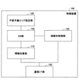
- FIG. 12 is a diagram showing a functional configuration example of the control device 100.
- the control device 100 includes an information collecting unit 110, a dead reserve area setting unit 120, a connection destination control unit 130, a DB unit 140, and a communication I / F unit 150.
- the information collecting unit 110 collects UE information (position, speed, strength of radio waves received from the base station, barometric pressure information, etc.). Further, when the control device 100 calculates the dead zone, the information collecting unit 110 collects the reception quality from the sensor 50 and the UE 10 and calculates the dead zone. Further, when the control device 100 does not calculate the dead zone, the information collecting unit 110 receives the calculated dead zone information from another device.
- UE information position, speed, strength of radio waves received from the base station, barometric pressure information, etc.
- the dead zone setting unit 120 sets a dead zone around each dead zone.
- the setting method is as described above.
- the connection destination control unit 130 determines whether or not the UE 10 has entered the dead reserve area by comparing the position of the UE 10 with the dead reserve area, and if it is determined that the UE 10 has entered, controls the connection destination for the UE 10. ..
- the DB unit 140 has a DB (example: FIG. 11) for storing the information collected by the information collecting unit 110 and the calculated information.
- the communication I / F unit 150 transmits / receives data.
- the dead reserve area setting unit 120 calculates the dead reserve area for the base station to which the UE 10 is connected and each peripheral base station to which the UE 10 can be connected.
- the calculated information on the dead reserve area is stored in the DB unit 140.
- the information collecting unit 110 collects UE information (position, speed, radio wave strength from the base station, barometric pressure information, etc.) from the UE 10.
- the collected information is stored in the DB unit 140.
- connection destination control unit 130 reads the position information of the UE 10 and the information of the dead reserve area from the DB unit 140, and the UE 10 determines whether or not the UE 10 is located in the dead reserve area of the connection base station. ..
- connection destination control unit 130 transmits an instruction to the UE 10 (or the connection destination base station) to switch (or make a redundant configuration) the connection line of the UE 10. do. If the determination result of S303 is No, the process returns to S301.
- control device 100 determines the entry into the dead reserve area of the UE 10 and gives a line switching instruction, but this is an example.
- the UE 10 may determine the entry into the dead reserve area and switch the line.
- a UE that makes a deadline reserve area entry determination and switches lines may be called a "control device".
- FIG. 14 shows an example of the configuration of the UE 10 when the UE 10 determines the entry into the dead reserve area and switches the line.
- the configuration of the UE 10 is the same as the configuration of the control device 100. That is, as shown in FIG. 14, the UE 10 has an information collecting unit 11, a dead reserve area setting unit 12, a connection destination control unit 13, a DB unit 14, and a communication I / F unit 15.
- the functions of each unit are the same as those of the corresponding functional unit in the control device 100, and are as follows.
- the information collecting unit 11 includes, for example, a position sensor such as GPS, a speed sensor, an acceleration sensor, and the like, and collects UE information (position, speed, radio wave intensity from a base station, pressure information, etc.) of the UE 10. Further, when the UE 10 calculates a dead zone, the information collecting unit 11 collects reception quality from the sensor 50 and another UE 10 and calculates the dead zone. Further, when the UE 10 does not calculate the dead zone, the information collecting unit 11 receives the calculated dead zone information from another device.
- a position sensor such as GPS, a speed sensor, an acceleration sensor, and the like
- UE information position, speed, radio wave intensity from a base station, pressure information, etc.
- the dead zone setting unit 12 sets a dead zone around each dead zone.
- the setting method is as described above.
- the connection destination control unit 13 determines whether or not the UE 10 has entered the dead reserve area by comparing the position of the UE 10 with the dead reserve area, and if it is determined that the UE 10 has entered, controls the connection destination of the UE 10. .. For example, the connection destination base station of the UE 10 is switched from the connection destination base station to another base station. Further, the connection destination control unit 13 may instruct the connection base station or the wireless LAN-AP to switch the connection.
- the DB unit 14 has a DB (example: FIG. 11) for storing information collected or calculated by the information collecting unit 11.
- the communication I / F unit 15 transmits / receives data.
- the operation of the UE 10 in the modification 10 is the same as the operation of the control device 100 shown in FIG.
- Each of the control device 100 and the UE 10 in the present embodiment can be realized by, for example, causing a computer to execute a program describing the processing contents described in the present embodiment.
- the "computer” used as the control device 100 may be a physical machine or a virtual machine on the cloud.
- the "hardware” described here is virtual hardware.
- the above program can be recorded on a computer-readable recording medium (portable memory, etc.), saved, and distributed. It is also possible to provide the above program through a network such as the Internet or e-mail.
- FIG. 15 is a diagram showing an example of the hardware configuration of the computer.
- the computer of FIG. 15 has a drive device 1000, an auxiliary storage device 1002, a memory device 1003, a CPU 1004, an interface device 1005, a display device 1006, an input device 1007, an output device 1008, and the like, which are connected to each other by a bus BS, respectively.
- the program that realizes the processing on the computer is provided by, for example, a recording medium 1001 such as a CD-ROM or a memory card.
- a recording medium 1001 such as a CD-ROM or a memory card.
- the program is installed in the auxiliary storage device 1002 from the recording medium 1001 via the drive device 1000.
- the program does not necessarily have to be installed from the recording medium 1001, and may be downloaded from another computer via the network.
- the auxiliary storage device 1002 stores the installed program and also stores necessary files, data, and the like.
- the memory device 1003 reads and stores the program from the auxiliary storage device 1002 when the program is instructed to start.
- the CPU 1004 realizes the function related to the control device 100 or the UE 10 according to the program stored in the memory device 1003.
- the interface device 1005 is used as an interface for connecting to a network, and functions as a transmitting unit and a receiving unit.
- the display device 1006 displays a GUI (Graphical User Interface) or the like by a program.
- the input device 1007 is composed of a keyboard, a mouse, buttons, a touch panel, and the like, and is used for inputting various operation instructions.
- the output device 1008 outputs the calculation result.
- a communication system having a terminal that communicates with a base station wirelessly and a control device.
- the terminal includes a transmission unit that transmits the position information of the terminal.
- the control device is The dead zone setting section that sets the area around the dead zone as the dead zone, and the dead zone setting section.
- An information gathering unit that acquires the location information of the terminal, By comparing the position information of the terminal with the dead reserve area, it is determined whether or not the terminal exists in the dead reserve area, and when it is determined that the terminal exists in the dead reserve area, the said.
- a communication system including a connection destination control unit that executes control for switching the connection destination of a terminal.
- the connection destination control unit When the terminal exists in a plurality of dead zones, the connection destination control unit connects the terminal to the base station having the longest distance from the dead zone among the base stations corresponding to the plurality of dead zones.
- the terminal transmits the position information of the terminal
- the control device Set the area around the dead zone as a dead zone, and set it as a dead zone. Acquire the location information of the terminal and By comparing the position information of the terminal with the dead reserve area, it is determined whether or not the terminal exists in the dead reserve area, and when it is determined that the terminal exists in the dead reserve area, the said.
- Connection destination control method that executes control to switch the connection destination of the terminal.
- the control device in a communication system having a terminal that wirelessly communicates with a base station and a control device.
- the dead zone setting section that sets the area around the dead zone as the dead zone, and the dead zone setting section.
- An information gathering unit that acquires the location information of the terminal, By comparing the position information of the terminal with the dead reserve area, it is determined whether or not the terminal exists in the dead reserve area, and when it is determined that the terminal exists in the dead reserve area, the said.
- a control device equipped with a connection destination control unit that executes control to switch the connection destination of the terminal. (Section 6) When the terminal exists in a plurality of dead zones, the connection destination control unit connects the terminal to the base station having the longest distance from the dead zone among the base stations corresponding to the plurality of dead zones. The control device according to paragraph 5 to be selected as.
Abstract
無線により基地局と通信する端末と、制御装置とを有する通信システムであって、前記端末は、前記端末の位置情報を送信する送信部を備え、前記制御装置は、不感地帯の周辺のエリアを不感予備エリアとして設定する不感予備エリア設定部と、前記端末の位置情報を取得する情報収集部と、前記端末の位置情報と前記不感予備エリアとを比較することにより、前記端末が前記不感予備エリアに存在するか否かを判断し、前記端末が前記不感予備エリアに存在すると判断した場合に、前記端末の接続先を切り替える制御を実行する接続先制御部と、を備える。
Description
本発明は、無線通信システムにおける通信品質の劣化や通信断を回避する技術に関連するものである。
3GPPにおいて5Gと呼ばれる無線通信システムの標準化(例えば非特許文献1)が進められ、5Gの通信サービスが開始されている。また、企業や自治体により構築される局所的な5Gシステムであるローカル5G(L5G)の検討、導入も進められている。
5Gには超高速、超低遅延、多数同時接続等の特徴があり、様々な無線アクセスに利用されることが期待される。特にL5Gにおいてはミッションクリティカルなアプリケーションの利用も想定されており、通信品質の維持がより厳密に求められている。また、L5Gの導入コストは他の無線システム(無線LAN)などと比較すると高価であることから、基地局数を限定するなどエリアを絞って導入されることが想定される。
3GPP TS 23.501 V16.4.0 (2020-03) (Release 16),"4 Architecture model and concepts"
5Gでは、3.7GHz帯、4.5GHz帯、及び28GHz帯の周波数が利用され、L5Gでは4.5GHz帯、及び28GHz帯の周波数を利用される。
しかし、ミリ波帯(28.2~29.1GHz)のような高周波数帯においては電波の直進性が高く、建物の柱や遮蔽物により電波の届きにくいエリアや不感地帯が生じる可能性がある。端末(UE)が電波の届きにくいエリアや不感地帯に進入した場合、通信品質の劣化(通信断を含む)が生じる場合がある。
本発明は上記の点に鑑みてなされたものであり、無線通信システムにおいて、端末が不感地帯へ進入することにより生じる通信品質の劣化を回避するための技術を提供することを目的とする。
開示の技術によれば、無線により基地局と通信する端末と、制御装置とを有する通信システムであって、
前記端末は、前記端末の位置情報を送信する送信部を備え、
前記制御装置は、
不感地帯の周辺のエリアを不感予備エリアとして設定する不感予備エリア設定部と、
前記端末の位置情報を取得する情報収集部と、
前記端末の位置情報と前記不感予備エリアとを比較することにより、前記端末が前記不感予備エリアに存在するか否かを判断し、前記端末が前記不感予備エリアに存在すると判断した場合に、前記端末の接続先を切り替える制御を実行する接続先制御部と、を備える
通信システムが提供される。
前記端末は、前記端末の位置情報を送信する送信部を備え、
前記制御装置は、
不感地帯の周辺のエリアを不感予備エリアとして設定する不感予備エリア設定部と、
前記端末の位置情報を取得する情報収集部と、
前記端末の位置情報と前記不感予備エリアとを比較することにより、前記端末が前記不感予備エリアに存在するか否かを判断し、前記端末が前記不感予備エリアに存在すると判断した場合に、前記端末の接続先を切り替える制御を実行する接続先制御部と、を備える
通信システムが提供される。
開示の技術によれば、無線通信システムにおいて、端末が不感地帯へ進入することにより生じる通信品質の劣化を回避するための技術が提供される。
以下、図面を参照して本発明の実施の形態(本実施の形態)を説明する。以下で説明する実施の形態は一例に過ぎず、本発明が適用される実施の形態は、以下の実施の形態に限られるわけではない。
本実施の形態において、「不感地帯」とは、基地局からの電波が届きにくいエリアであるものとする。「電波が届きにくいエリア」とは、例えば、ある閾値以下の電力の電波しか届かないエリア(電波が全く届かないエリアを含む)である。また、以下の説明では、端末をUEと記載する。UEはUser Equipmentの略称である。
(課題、実施の形態の概要)
まず、本実施の形態の形態に係る技術を適用しない場合の動作について図1、図2を参照して説明する。
まず、本実施の形態の形態に係る技術を適用しない場合の動作について図1、図2を参照して説明する。
図1に示すように、基地局1と基地局2が存在し、それぞれの電波到達範囲がエリアA、エリアBとして示されている。図1に示される状態において、UE10は基地局1に接続している。図示された位置に壁などの遮蔽物Cが存在し、基地局1から見て遮蔽物Cの後方のエリアが不感地帯になっている。
このような環境において、UE10が不感地帯を通過して、エリアBに移動する場合の通信品質(例としてUE10におけるスループット)の変化を図2に示している。図2に示すとおり、UE10が不感地帯を通過している期間、スループットが0になる。
本実施の形態では、上記のような不感地帯への進入による通信品質の劣化を回避するために、不感地帯の周辺に不感予備エリアを設定し、後述する制御装置100が、UE10の不感予備エリアへの進入を検知することで、事前にUE10に対して別回線(別基地局など)への接続切替えや、複数回線接続による冗長化を行わせることとしている。以下、本実施の形態を詳細に説明する。
(システム構成)
図3に、本実施の形態における通信システムの全体構成例を示す。図3に示すとおり、本システムは、制御装置100、キャリア網200、キャリア網300、L5G事業者網400を有し、これらがインターネット500に接続されている。また、UE10が、その位置に応じて、L5G事業者網400の基地局430等と無線により通信を行う。
図3に、本実施の形態における通信システムの全体構成例を示す。図3に示すとおり、本システムは、制御装置100、キャリア網200、キャリア網300、L5G事業者網400を有し、これらがインターネット500に接続されている。また、UE10が、その位置に応じて、L5G事業者網400の基地局430等と無線により通信を行う。
キャリア網200は、LTEコア網210及び基地局220を有する。なお、図3において、各網には基地局が1つだけ示されているが、これは図示の便宜のためであり、実際には多数の基地局が存在し得る。
キャリア網300は、5Gコア網310及び基地局320を有する。L5G事業者網400は、集約SW410、L5Gコア網420、基地局430、無線LAN-AP440を有する。
キャリア網200、キャリア網300、L5G事業者網400のいずれにおいても、網内には無線LAN‐APやIoT端末等の複数の無線システムが含まれる場合がある。図3は、一例として、L5G事業者網400に無線LAN-AP440が存在する場合の例を示している。
制御装置100は、本発明に係る制御処理を実行する装置であり、クラウド上に備えられた仮想サーバ、あるいは物理ネットワーク上に備えられた物理サーバである。制御装置100の配置場所は特定の場所に限定されないが、制御範囲に応じて配置場所を決めてもよい。例えば、L5G事業者網400に接続するUE10を制御することを想定した場合、L5G事業者網400に近い場所に制御装置100を設置することとしてよい。
UE10からの情報は、接続先の無線システム(LTE、5G、L5G、無線LAN、IoT端末等)を介して制御装置100に送信される。
(動作概要)
図4、図5を参照して、本実施の形態におけるシステムの動作概要を説明する。図4において、図1の場合と同様に、基地局1と基地局2が存在し、それぞれの電波到達範囲がエリアA、エリアBとして示されている。図示された位置に壁などの遮蔽物Cが存在し、基地局1から見て遮蔽物Cの後方のエリアは基地局1の不感地帯になっている。なお、基地局1と基地局2はそれぞれ、キャリア網200、300、L5G事業者網500のうちのいずれの基地局であってもよい。また、基地局1と基地局2はそれぞれ、無線LAN-APであってもよい。
図4、図5を参照して、本実施の形態におけるシステムの動作概要を説明する。図4において、図1の場合と同様に、基地局1と基地局2が存在し、それぞれの電波到達範囲がエリアA、エリアBとして示されている。図示された位置に壁などの遮蔽物Cが存在し、基地局1から見て遮蔽物Cの後方のエリアは基地局1の不感地帯になっている。なお、基地局1と基地局2はそれぞれ、キャリア網200、300、L5G事業者網500のうちのいずれの基地局であってもよい。また、基地局1と基地局2はそれぞれ、無線LAN-APであってもよい。
このような環境において、UE10は、エリアAから不感地帯を通過してエリアBに移動する。
本実施の形態では、図4に示すように、不感地帯の周辺に不感予備エリアが設定される。制御装置100は、UE10の位置情報に基づいて、UE10が、不感予備エリアに進入したか否かを判断する。
制御装置100は、UE10が不感予備エリアに進入したと判断した場合、例えば、UE10に対して、基地局1から基地局2への回線切替を指示する。制御装置100は、UE10に対して、基地局1と基地局2の両方に接続して冗長回線を使用することを指示することとしてもよい。なお、上記の回線切替や冗長回線使用の指示は、基地局1に対して行うこととしてもよい。
上記の制御装置100による指示により、UE10は、不感地帯に進入する前に基地局2と通信できるので、基地局1に対する不感地帯による通信品質の劣化を回避できる。よって、図5に示すように、通品品質の劣化無しに、基地局1から基地局2への接続先の切り替えを行うことができる。
(不感予備エリア進入検知方法)
制御装置100が、UE10の不感予備エリアへの進入を検知して回線切替を行う処理内容の例を、図6のフローチャートの手順に沿ってより具体的に説明する。図7も適宜参照する。
制御装置100が、UE10の不感予備エリアへの進入を検知して回線切替を行う処理内容の例を、図6のフローチャートの手順に沿ってより具体的に説明する。図7も適宜参照する。
<S101>
S101において、制御装置100は、UE10の位置情報を定期的に収集する。なお、本実施の形態では、UE10がGPS装置を搭載しており、GPS装置により得られた位置情報がUE10から制御装置100に送信されることを想定しているが、位置情報の収集方法はこの方法に限られるわけではない。例えば、UE10の周辺(路側等)に備えられたセンサがUE10の位置情報を取得してそれを制御装置100に送信してもよい。
S101において、制御装置100は、UE10の位置情報を定期的に収集する。なお、本実施の形態では、UE10がGPS装置を搭載しており、GPS装置により得られた位置情報がUE10から制御装置100に送信されることを想定しているが、位置情報の収集方法はこの方法に限られるわけではない。例えば、UE10の周辺(路側等)に備えられたセンサがUE10の位置情報を取得してそれを制御装置100に送信してもよい。
また、制御装置100が収集するUE10の位置情報は、例えば、x-y座標や緯度・経度であるが、これらに限られず、高さを含む3次元の位置情報であってもよい。
また、制御装置100は、UE10の位置情報と、UE10の位置における気圧センサ情報(UE10の位置における気圧)を収集してもよい。制御装置100は、気圧センサ情報により、UE10の高さ方向の位置を取得できる。建物内の場合など、3次元的にUE10の位置を考慮する場合に高さ方向の位置を使用できる。また、制御装置100は、UE10の速さや、UE10における基地局からの電波強度をUE10から収集してもよい。気圧センサ情報に関しては、UE10が備える気圧センサの情報であってもよいし、UE10の周辺に備えられた気圧センサの情報であってもよい。
<S102>
制御装置100は、不感地帯の位置情報を保持している。図7に示すように、例えば、ある不感地帯が半径Rの円である場合、制御装置100は、当該不感地帯に対する不感予備エリアを、不感地帯の中心を中心とする半径R+rの円から、不感地帯(半径Rの円)を除いたドーナツ状のエリアとして設定する。つまり、不感予備エリアは、不感地帯の中心を中心とする、半径R以上r以下のエリアである。「r」は予め定めておくこととしてもよいし、UE10の速さ等に応じて動的に決定してもよい。
制御装置100は、不感地帯の位置情報を保持している。図7に示すように、例えば、ある不感地帯が半径Rの円である場合、制御装置100は、当該不感地帯に対する不感予備エリアを、不感地帯の中心を中心とする半径R+rの円から、不感地帯(半径Rの円)を除いたドーナツ状のエリアとして設定する。つまり、不感予備エリアは、不感地帯の中心を中心とする、半径R以上r以下のエリアである。「r」は予め定めておくこととしてもよいし、UE10の速さ等に応じて動的に決定してもよい。
S102において、制御装置100は、S101で取得したUE10の現在の位置と、UE10が接続している基地局における不感地帯に対する不感予備エリアとを比較し、UE10の位置が当該不感予備エリア内にあるか否か(つまり、UE10が不感予備エリアに進入したか否か)を判断する。UE10が不感予備エリアに進入したと判断した場合、S103に進む。なお、上記の比較においては、制御装置100は、S101で取得したUE10の現在の位置と、UE10が接続している基地局の周辺の各基地局における不感地帯に対する不感予備エリアとの比較も行う。
<S103>
S103において、制御装置100は、UE10(又はUE10の接続基地局)に対して回線の切替指示を送信する。前述したように、冗長回線接続を指示してもよい。回線の切替(あるいは冗長構成)の接続先の基地局は、周辺の基地局のうち、UE10がその不感予備エリアに位置していない基地局とする。
S103において、制御装置100は、UE10(又はUE10の接続基地局)に対して回線の切替指示を送信する。前述したように、冗長回線接続を指示してもよい。回線の切替(あるいは冗長構成)の接続先の基地局は、周辺の基地局のうち、UE10がその不感予備エリアに位置していない基地局とする。
制御装置100は、UE10の位置が、周辺の全ての基地局(UE10が接続可能な周辺の全ての基地局)の不感予備エリア内にあると判断した場合、接続基地局と当該全ての周辺基地局のうち、UE10が位置する不感予備エリアに対応する不感地帯の中心からの距離が最も大きな基地局を選択し、その基地局をUE10の接続先とする。
接続可能な基地局全てにおいてUE10が不感予備エリアに位置する場合、不感地帯中心と基地局との間の距離が大きいほど、不感地帯の影響が小さくなるため、上記のような基地局選択を行っている。
接続先基地局を1つとする切替制御を行う場合において、例えば、図8に示すように、UE10が、基地局1に対する不感予備エリアAと基地局2に対する不感予備エリアBに位置する場合、制御装置100は、UE10を、中心との距離が大きな基地局2に接続させる。
(不感地帯算出方法)
次に、不感地帯算出方法について説明する。本実施の形態では、制御装置100が不感地帯算出処理を行うこととしているが、これは一例である。制御装置100以外の装置が不感地帯算出処理を行い、制御装置100は、当該装置から不感地帯の情報を受信することとしてもよい。
次に、不感地帯算出方法について説明する。本実施の形態では、制御装置100が不感地帯算出処理を行うこととしているが、これは一例である。制御装置100以外の装置が不感地帯算出処理を行い、制御装置100は、当該装置から不感地帯の情報を受信することとしてもよい。
本実施の形態では、図9に示すように、サービス提供エリア内に複数のセンサ50を配置する。サービス提供エリアとは、基地局のサービス提供エリアである。図9は、例として、基地局60のサービス提供エリアが示されている。
各センサ50は、受信品質を計測し、計測結果を制御装置100にフィードバックする機能を有する。各UE(図9には、UE10A、10Bが示されている)も受信品質を計測し、計測結果を制御装置100にフィードバックする機能を有する。
センサ50と基地局60との間は、無線接続されてもよいし、有線接続されてもよい。センサ50と基地局60との間が無線接続される場合、各センサ50は、UE10と同様の基地局との通信機能を具備し、基地局60からの割り当てによりユーザデータ領域又は制御メッセージを用いてフィードバック信号を基地局60に送信することができる。
図10のフローチャートを参照して、不感地帯算出の手順例を説明する。図10の処理の前提として、制御装置100は、各センサ50の位置情報を既に保持しているとする。また、図10の処理は、基地局毎に実行される。つまり、基地局毎に不感地帯の情報が得られる。また、図10の処理は、定期的に実行される。すなわち、不感地帯の情報は定期的に更新される。
<S201>
S201において、各センサ50が受信品質(受信電波情報)を計測し、制御装置100へ送信する。各UE10は、自身の位置情報と受信品質を制御装置100へ送信する。
S201において、各センサ50が受信品質(受信電波情報)を計測し、制御装置100へ送信する。各UE10は、自身の位置情報と受信品質を制御装置100へ送信する。
受信品質は、例えば、SS-RSRP、CSI-RSRP、NR-RSSI、CSI-RSSI、SS-RSRQ、CSI-RSRQ、SS-SINR、CSI-SINRのいずれか1つ、又は、いずれか複数の組み合わせである。受信品質の送信には、対象無線システムの上り通信を使用してもよいし、有線接続や無線LAN等の別のアクセス手段を使用してもよい。
<S202>
S202において、制御装置100は、受信した受信品質と、その受信品質の送信元のセンサ50に紐づく位置情報に基づいて、不感地帯が検出された位置を把握する。
S202において、制御装置100は、受信した受信品質と、その受信品質の送信元のセンサ50に紐づく位置情報に基づいて、不感地帯が検出された位置を把握する。
例えば、制御装置100は、ある位置のセンサから受信した受信品質が予め定めた閾値以上であれば、その位置の受信電波状況は良好(Good)であると判断し、受信品質が予め定めた閾値以上でなければ、その位置の受信電波状況は不良(Bad)であると判断する。
制御装置100は、受信電波状況が不良(Bad)であると判断した位置を不感地帯の位置であると決定する。なお、位置は、x‐y座標や経度・緯度等の2次元の位置であることを想定しているが、屋内施設等を対象とする際には、高さ方向(z軸方向)を加えて、3次元位置を対象としてもよい。3次元の場合、不感地帯は、3次元形状(例えば球)になる。
<S203>
S203において、制御装置100は、不感地帯を検出した位置を中心に、半径Rの範囲を不感地帯として決定し、不感地帯の情報(例:円の半径と中心位置)をDBに格納する。Rは、予め定めておいた値である。なお、このようにして不感地帯を設定することは一例である。
S203において、制御装置100は、不感地帯を検出した位置を中心に、半径Rの範囲を不感地帯として決定し、不感地帯の情報(例:円の半径と中心位置)をDBに格納する。Rは、予め定めておいた値である。なお、このようにして不感地帯を設定することは一例である。
図11に、DBに格納された不感地帯の情報の例を示す。図11の例では、検出された不感ポイント毎に、その位置と不感地帯の情報が格納されている。なお、図11において例えば(p-R~p+R,q-R~q+R)は、(p,q)を中心とする半径Rの円を意味する。
(制御装置の装置構成例、動作例)
次に、上述した処理を実行する制御装置100の装置構成例を説明する。図12は、制御装置100の機能構成例を示す図である。図12に示すように、制御装置100は、情報収集部110、不感予備エリア設定部120、接続先制御部130、DB部140、通信I/F部150を有する。
次に、上述した処理を実行する制御装置100の装置構成例を説明する。図12は、制御装置100の機能構成例を示す図である。図12に示すように、制御装置100は、情報収集部110、不感予備エリア設定部120、接続先制御部130、DB部140、通信I/F部150を有する。
情報収集部110は、UE情報(位置、速さ、基地局から受信する電波の強度、気圧情報等)を収集する。また、制御装置100が不感地帯を算出する場合、情報収集部110は、センサ50及びUE10から受信品質を収集し、不感地帯を算出する。また、制御装置100が不感地帯を算出しない場合、情報収集部110は、算出済みの不感地帯の情報を他の装置から受信する。
不感予備エリア設定部120は、各不感地帯の周辺に不感予備エリアを設定する。設定方法は、前述したとおりである。接続先制御部130は、UE10の位置と不感予備エリアを比較することで、UE10が不感予備エリアに進入したか否かを判断し、進入したと判断した場合に、UE10に対する接続先制御を行う。
DB部140は、情報収集部110により収集した情報や算出した情報を格納するDB(例:図11)を有する。通信I/F部150は、データの送受信を行う。
図13のフローチャートを参照して、上記の構成を備える制御装置100の動作例を説明する。図13のフローでは、DB部140に既に不感地帯情報が格納されているとする。
S301において、不感予備エリア設定部120は、UE10が接続している基地局、及び、UE10が接続可能な周辺の各基地局に対する不感予備エリアを算出する。算出した不感予備エリアの情報はDB部140に格納される。
S302において、情報収集部110が、UE10からUE情報(位置、速度、基地局からの電波強度、気圧情報等)を収集する。収集した情報はDB部140に格納される。
S303において、接続先制御部130が、DB部140からUE10の位置情報と不感予備エリアの情報を読み出し、UE10が、接続基地局の不感予備エリア内にUE10が位置しているか否かを判断する。
S303の判定結果がYesである場合、S304に進み、接続先制御部130が、UE10(又は接続先の基地局)に対して、UE10の接続回線を切り替える(又は冗長構成にする)指示を送信する。S303の判定結果がNoの場合、S301に戻る。
(変形例)
これまでに説明した例では、制御装置100がUE10の不感予備エリア進入判断を行って、回線切替指示を行うこととしているが、これは一例である。UE10が、不感予備エリア進入判断を行って、回線切替を行うことととしてもよい。不感予備エリア進入判断を行って、回線切替を行うUEを「制御装置」と呼んでもよい。
これまでに説明した例では、制御装置100がUE10の不感予備エリア進入判断を行って、回線切替指示を行うこととしているが、これは一例である。UE10が、不感予備エリア進入判断を行って、回線切替を行うことととしてもよい。不感予備エリア進入判断を行って、回線切替を行うUEを「制御装置」と呼んでもよい。
UE10が、不感予備エリア進入判断を行って、回線切替を行う場合のUE10の構成例を、図14に示す。図14に示すように、UE10の構成は制御装置100の構成と同様の構成である。すなわち、図14に示すように、UE10は、情報収集部11、不感予備エリア設定部12、接続先制御部13、DB部14、通信I/F部15を有する。各部の機能は、制御装置100における該当機能部と同様であり下記のとおりである。
情報収集部11は、例えばGPS等の位置センサ、速度センサ、加速度センサ等を含み、UE10のUE情報(位置、速さ、基地局からの電波強度、気圧情報等)を収集する。また、UE10が不感地帯を算出する場合、情報収集部11は、センサ50及び他のUE10から受信品質を収集し、不感地帯を算出する。また、UE10が不感地帯を算出しない場合、情報収集部11は、算出済みの不感地帯の情報を他の装置から受信する。
不感予備エリア設定部12は、各不感地帯の周辺に不感予備エリアを設定する。設定方法は、前述したとおりである。接続先制御部13は、UE10の位置と不感予備エリアを比較することで、UE10が不感予備エリアに進入したか否かを判断し、進入したと判断した場合に、UE10の接続先制御を行う。例えば、UE10の接続先の基地局を接続先基地局から別の基地局に切り替える。また、接続先制御部13は、接続基地局や無線LAN-APに対して接続切替を指示してもよい。
DB部14は、情報収集部11により収集あるいは算出した情報を格納するDB(例:図11)を有する。通信I/F部15は、データの送受信を行う。変形例10におけるUE10の動作は、図13に示した制御装置100の動作と同様である。
(ハードウェア構成例)
本実施の形態(変形例を含む)における制御装置100及びUE10はそれぞれ、例えば、コンピュータに、本実施の形態で説明する処理内容を記述したプログラムを実行させることにより実現可能である。なお、制御装置100として使用される「コンピュータ」は、物理マシンであってもよいし、クラウド上の仮想マシンであってもよい。仮想マシンを使用する場合、ここで説明する「ハードウェア」は仮想的なハードウェアである。
本実施の形態(変形例を含む)における制御装置100及びUE10はそれぞれ、例えば、コンピュータに、本実施の形態で説明する処理内容を記述したプログラムを実行させることにより実現可能である。なお、制御装置100として使用される「コンピュータ」は、物理マシンであってもよいし、クラウド上の仮想マシンであってもよい。仮想マシンを使用する場合、ここで説明する「ハードウェア」は仮想的なハードウェアである。
上記プログラムは、コンピュータが読み取り可能な記録媒体(可搬メモリ等)に記録して、保存したり、配布したりすることが可能である。また、上記プログラムをインターネットや電子メール等、ネットワークを通して提供することも可能である。
図15は、上記コンピュータのハードウェア構成例を示す図である。図15のコンピュータは、それぞれバスBSで相互に接続されているドライブ装置1000、補助記憶装置1002、メモリ装置1003、CPU1004、インタフェース装置1005、表示装置1006、入力装置1007、出力装置1008等を有する。
当該コンピュータでの処理を実現するプログラムは、例えば、CD-ROM又はメモリカード等の記録媒体1001によって提供される。プログラムを記憶した記録媒体1001がドライブ装置1000にセットされると、プログラムが記録媒体1001からドライブ装置1000を介して補助記憶装置1002にインストールされる。但し、プログラムのインストールは必ずしも記録媒体1001より行う必要はなく、ネットワークを介して他のコンピュータよりダウンロードするようにしてもよい。補助記憶装置1002は、インストールされたプログラムを格納すると共に、必要なファイルやデータ等を格納する。
メモリ装置1003は、プログラムの起動指示があった場合に、補助記憶装置1002からプログラムを読み出して格納する。CPU1004は、メモリ装置1003に格納されたプログラムに従って、制御装置100又はUE10に係る機能を実現する。インタフェース装置1005は、ネットワークに接続するためのインタフェースとして用いられ、送信部及び受信部として機能する。表示装置1006はプログラムによるGUI(Graphical User Interface)等を表示する。入力装置1007はキーボード及びマウス、ボタン、又はタッチパネル等で構成され、様々な操作指示を入力させるために用いられる。出力装置1008は演算結果を出力する。
(実施の形態の効果)
以上説明した本実施の形態に係る技術により、UE10の不感地帯への進入前に別回線への切替や複数回線接続による冗長化を行うことができ、通信品質の劣化や瞬断を回避することが可能となる。
以上説明した本実施の形態に係る技術により、UE10の不感地帯への進入前に別回線への切替や複数回線接続による冗長化を行うことができ、通信品質の劣化や瞬断を回避することが可能となる。
(実施の形態のまとめ)
本明細書には、少なくとも下記の各項に記載した通信システム、接続先制御方法、制御装置、及びプログラムが記載されている。
(第1項)
無線により基地局と通信する端末と、制御装置とを有する通信システムであって、
前記端末は、前記端末の位置情報を送信する送信部を備え、
前記制御装置は、
不感地帯の周辺のエリアを不感予備エリアとして設定する不感予備エリア設定部と、
前記端末の位置情報を取得する情報収集部と、
前記端末の位置情報と前記不感予備エリアとを比較することにより、前記端末が前記不感予備エリアに存在するか否かを判断し、前記端末が前記不感予備エリアに存在すると判断した場合に、前記端末の接続先を切り替える制御を実行する接続先制御部と、を備える
通信システム。
(第2項)
前記接続先制御部は、前記端末が複数の不感予備エリアに存在する場合に、複数の不感予備エリアに対応する基地局のうち、不感地帯からの距離が最も大きな基地局を前記端末の接続先として選択する
第1項に記載の通信システム。
(第3項)
前記情報収集部は、複数のセンサから受信した受信品質に基づいて、前記不感地帯を算出する
第1項又は第2項に記載の通信システム。
(第4項)
無線により基地局と通信する端末と、制御装置とを有する通信システムにおける接続先制御方法であって、
前記端末が、前記端末の位置情報を送信し、
前記制御装置が、
不感地帯の周辺のエリアを不感予備エリアとして設定し、
前記端末の位置情報を取得し、
前記端末の位置情報と前記不感予備エリアとを比較することにより、前記端末が前記不感予備エリアに存在するか否かを判断し、前記端末が前記不感予備エリアに存在すると判断した場合に、前記端末の接続先を切り替える制御を実行する
接続先制御方法。
(第5項)
無線により基地局と通信する端末と、制御装置とを有する通信システムにおける前記制御装置であって、
不感地帯の周辺のエリアを不感予備エリアとして設定する不感予備エリア設定部と、
前記端末の位置情報を取得する情報収集部と、
前記端末の位置情報と前記不感予備エリアとを比較することにより、前記端末が前記不感予備エリアに存在するか否かを判断し、前記端末が前記不感予備エリアに存在すると判断した場合に、前記端末の接続先を切り替える制御を実行する接続先制御部と
を備える制御装置。
(第6項)
前記接続先制御部は、前記端末が複数の不感予備エリアに存在する場合に、複数の不感予備エリアに対応する基地局のうち、不感地帯からの距離が最も大きな基地局を前記端末の接続先として選択する
第5項に記載の制御装置。
(第7項)
前記情報収集部は、複数のセンサから受信した受信品質に基づいて、前記不感地帯を算出する
第5項又は第6項に記載の制御装置。
(第8項)
コンピュータを、第5項ないし第7項のうちいずれか1項に記載の制御装置における各部として機能させるためのプログラム。
以上、本実施の形態について説明したが、本発明はかかる特定の実施形態に限定されるものではなく、特許請求の範囲に記載された本発明の要旨の範囲内において、種々の変形・変更が可能である。
10 端末(UE)
11 情報収集部
12 不感予備エリア設定部
13 接続先制御部
14 DB部
15 通信I/F部
50 センサ
60、220、320、430 基地局
100 制御装置
110 情報収集部
120 不感予備エリア設定部
130 接続先制御部
140 DB部
150 通信I/F部
200、300 キャリア網
210 LTEコア網
310、420 5Gコア網
400 L5G事業者網
500 インターネット
410 集約SW
440 無線LAN-AP
1000 ドライブ装置
1001 記録媒体
1002 補助記憶装置
1003 メモリ装置
1004 CPU
1005 インタフェース装置
1006 表示装置
1007 入力装置
1008 出力装置
Claims (8)
- 無線により基地局と通信する端末と、制御装置とを有する通信システムであって、
前記端末は、前記端末の位置情報を送信する送信部を備え、
前記制御装置は、
不感地帯の周辺のエリアを不感予備エリアとして設定する不感予備エリア設定部と、
前記端末の位置情報を取得する情報収集部と、
前記端末の位置情報と前記不感予備エリアとを比較することにより、前記端末が前記不感予備エリアに存在するか否かを判断し、前記端末が前記不感予備エリアに存在すると判断した場合に、前記端末の接続先を切り替える制御を実行する接続先制御部と、を備える
通信システム。 - 前記接続先制御部は、前記端末が複数の不感予備エリアに存在する場合に、複数の不感予備エリアに対応する基地局のうち、不感地帯からの距離が最も大きな基地局を前記端末の接続先として選択する
請求項1に記載の通信システム。 - 前記情報収集部は、複数のセンサから受信した受信品質に基づいて、前記不感地帯を算出する
請求項1又は2に記載の通信システム。 - 無線により基地局と通信する端末と、制御装置とを有する通信システムにおける接続先制御方法であって、
前記端末が、前記端末の位置情報を送信し、
前記制御装置が、
不感地帯の周辺のエリアを不感予備エリアとして設定し、
前記端末の位置情報を取得し、
前記端末の位置情報と前記不感予備エリアとを比較することにより、前記端末が前記不感予備エリアに存在するか否かを判断し、前記端末が前記不感予備エリアに存在すると判断した場合に、前記端末の接続先を切り替える制御を実行する
接続先制御方法。 - 無線により基地局と通信する端末と、制御装置とを有する通信システムにおける前記制御装置であって、
不感地帯の周辺のエリアを不感予備エリアとして設定する不感予備エリア設定部と、
前記端末の位置情報を取得する情報収集部と、
前記端末の位置情報と前記不感予備エリアとを比較することにより、前記端末が前記不感予備エリアに存在するか否かを判断し、前記端末が前記不感予備エリアに存在すると判断した場合に、前記端末の接続先を切り替える制御を実行する接続先制御部と
を備える制御装置。 - 前記接続先制御部は、前記端末が複数の不感予備エリアに存在する場合に、複数の不感予備エリアに対応する基地局のうち、不感地帯からの距離が最も大きな基地局を前記端末の接続先として選択する
請求項5に記載の制御装置。 - 前記情報収集部は、複数のセンサから受信した受信品質に基づいて、前記不感地帯を算出する
請求項5又は6に記載の制御装置。 - コンピュータを、請求項5ないし7のうちいずれか1項に記載の制御装置における各部として機能させるためのプログラム。
Priority Applications (3)
| Application Number | Priority Date | Filing Date | Title |
|---|---|---|---|
| PCT/JP2020/028756 WO2022024196A1 (ja) | 2020-07-27 | 2020-07-27 | 通信システム、接続先制御方法、制御装置、及びプログラム |
| US18/016,248 US20230276335A1 (en) | 2020-07-27 | 2020-07-27 | Communication system, connection destination control method, control apparatus and program |
| JP2022539815A JP7428255B2 (ja) | 2020-07-27 | 2020-07-27 | 通信システム、接続先制御方法、制御装置、及びプログラム |
Applications Claiming Priority (1)
| Application Number | Priority Date | Filing Date | Title |
|---|---|---|---|
| PCT/JP2020/028756 WO2022024196A1 (ja) | 2020-07-27 | 2020-07-27 | 通信システム、接続先制御方法、制御装置、及びプログラム |
Publications (1)
| Publication Number | Publication Date |
|---|---|
| WO2022024196A1 true WO2022024196A1 (ja) | 2022-02-03 |
Family
ID=80037861
Family Applications (1)
| Application Number | Title | Priority Date | Filing Date |
|---|---|---|---|
| PCT/JP2020/028756 WO2022024196A1 (ja) | 2020-07-27 | 2020-07-27 | 通信システム、接続先制御方法、制御装置、及びプログラム |
Country Status (3)
| Country | Link |
|---|---|
| US (1) | US20230276335A1 (ja) |
| JP (1) | JP7428255B2 (ja) |
| WO (1) | WO2022024196A1 (ja) |
Citations (1)
| Publication number | Priority date | Publication date | Assignee | Title |
|---|---|---|---|---|
| JP2019022089A (ja) * | 2017-07-18 | 2019-02-07 | パナソニック株式会社 | 通信装置、通信システム、接続先制御方法、および伝送レート制御方法 |
Family Cites Families (2)
| Publication number | Priority date | Publication date | Assignee | Title |
|---|---|---|---|---|
| JP4897716B2 (ja) | 2008-01-29 | 2012-03-14 | 日本電信電話株式会社 | 無線通信システム、運用管理サーバ装置および無線基地局制御方法 |
| JP2013038583A (ja) | 2011-08-08 | 2013-02-21 | Nec Corp | 無線ネットワークシステム、ネットワーク管理装置及び劣化検出方法 |
-
2020
- 2020-07-27 WO PCT/JP2020/028756 patent/WO2022024196A1/ja active Application Filing
- 2020-07-27 JP JP2022539815A patent/JP7428255B2/ja active Active
- 2020-07-27 US US18/016,248 patent/US20230276335A1/en active Pending
Patent Citations (1)
| Publication number | Priority date | Publication date | Assignee | Title |
|---|---|---|---|---|
| JP2019022089A (ja) * | 2017-07-18 | 2019-02-07 | パナソニック株式会社 | 通信装置、通信システム、接続先制御方法、および伝送レート制御方法 |
Also Published As
| Publication number | Publication date |
|---|---|
| JP7428255B2 (ja) | 2024-02-06 |
| US20230276335A1 (en) | 2023-08-31 |
| JPWO2022024196A1 (ja) | 2022-02-03 |
Similar Documents
| Publication | Publication Date | Title |
|---|---|---|
| KR102525483B1 (ko) | 측정 방법 및 장치 | |
| US11190950B2 (en) | Communication system, communication management method, and network management apparatus | |
| CN101911533B (zh) | 用于多模式系统中频谱共享的方法以及相关设备 | |
| CN109541655B (zh) | 一种差分定位系统、方法 | |
| US20110176508A1 (en) | Frequency Band Coordination Method and Radio Communication Apparatus in Cognitive Radio System | |
| JP2002320258A (ja) | 無線通信システム | |
| US10588067B2 (en) | Terminal apparatus, communication system, and connection-destination selection method | |
| EP3255941B1 (en) | Mobile terminal positioning method and apparatus | |
| EP4021052A1 (en) | Pathloss drop trusted agent misbehavior detection | |
| US20220330134A1 (en) | Communication device, communication method, and communication system | |
| US20220394717A1 (en) | Location-matrix based user equipment band scanning | |
| CN113574963A (zh) | 控制装置、控制方法以及程序 | |
| WO2022024196A1 (ja) | 通信システム、接続先制御方法、制御装置、及びプログラム | |
| WO2022024197A1 (ja) | 通信システム、接続先制御方法、制御装置、及びプログラム | |
| WO2015057767A1 (en) | Selecting an access point for determining the position of a mobile device based on access point related traffic load information | |
| WO2022024198A1 (ja) | 通信システム、接続先制御方法、制御装置、及びプログラム | |
| CN111246373B (zh) | 一种通信距离计算方法及装置 | |
| JP2007166448A (ja) | 無線通信システム及び基地局切り替え装置 | |
| KR20190082500A (ko) | 차량간 데이터 통신 방법과 이를 수행하기 위한 장치 및 시스템 | |
| CN104796904A (zh) | 共享型节点和网络节点的实现方法和装置 | |
| KR20130123087A (ko) | 단말 위치 추적 방법 및 장치 | |
| WO2020202381A1 (ja) | 基地局、端末装置、制御方法、及びプログラム | |
| JP5872926B2 (ja) | 電波環境管理システムおよび電波環境管理方法 | |
| JP2011061336A (ja) | 移動通信システムおよび移動通信システムにおける移動機の位置標定方法ならびに移動機情報表示方法。 | |
| JP2018042078A (ja) | 無線ネットワーク構築支援システム、及び、無線ネットワーク構築支援方法 |
Legal Events
| Date | Code | Title | Description |
|---|---|---|---|
| 121 | Ep: the epo has been informed by wipo that ep was designated in this application |
Ref document number: 20947409 Country of ref document: EP Kind code of ref document: A1 |
|
| ENP | Entry into the national phase |
Ref document number: 2022539815 Country of ref document: JP Kind code of ref document: A |
|
| NENP | Non-entry into the national phase |
Ref country code: DE |
|
| 122 | Ep: pct application non-entry in european phase |
Ref document number: 20947409 Country of ref document: EP Kind code of ref document: A1 |