WO2022019074A1 - 電動機 - Google Patents
電動機 Download PDFInfo
- Publication number
- WO2022019074A1 WO2022019074A1 PCT/JP2021/024801 JP2021024801W WO2022019074A1 WO 2022019074 A1 WO2022019074 A1 WO 2022019074A1 JP 2021024801 W JP2021024801 W JP 2021024801W WO 2022019074 A1 WO2022019074 A1 WO 2022019074A1
- Authority
- WO
- WIPO (PCT)
- Prior art keywords
- rotor
- iron core
- stator
- motor
- magnet
- Prior art date
- Legal status (The legal status is an assumption and is not a legal conclusion. Google has not performed a legal analysis and makes no representation as to the accuracy of the status listed.)
- Ceased
Links
Images


Classifications
-
- H—ELECTRICITY
- H02—GENERATION; CONVERSION OR DISTRIBUTION OF ELECTRIC POWER
- H02K—DYNAMO-ELECTRIC MACHINES
- H02K1/00—Details of the magnetic circuit
- H02K1/06—Details of the magnetic circuit characterised by the shape, form or construction
- H02K1/22—Rotating parts of the magnetic circuit
- H02K1/27—Rotor cores with permanent magnets
- H02K1/2706—Inner rotors
- H02K1/272—Inner rotors the magnetisation axis of the magnets being perpendicular to the rotor axis
- H02K1/274—Inner rotors the magnetisation axis of the magnets being perpendicular to the rotor axis the rotor consisting of two or more circumferentially positioned magnets
- H02K1/2753—Inner rotors the magnetisation axis of the magnets being perpendicular to the rotor axis the rotor consisting of two or more circumferentially positioned magnets the rotor consisting of magnets or groups of magnets arranged with alternating polarity
- H02K1/276—Magnets embedded in the magnetic core, e.g. interior permanent magnets [IPM]
-
- H—ELECTRICITY
- H02—GENERATION; CONVERSION OR DISTRIBUTION OF ELECTRIC POWER
- H02K—DYNAMO-ELECTRIC MACHINES
- H02K1/00—Details of the magnetic circuit
- H02K1/02—Details of the magnetic circuit characterised by the magnetic material
-
- H—ELECTRICITY
- H02—GENERATION; CONVERSION OR DISTRIBUTION OF ELECTRIC POWER
- H02K—DYNAMO-ELECTRIC MACHINES
- H02K1/00—Details of the magnetic circuit
- H02K1/04—Details of the magnetic circuit characterised by the material used for insulating the magnetic circuit or parts thereof
-
- H—ELECTRICITY
- H02—GENERATION; CONVERSION OR DISTRIBUTION OF ELECTRIC POWER
- H02K—DYNAMO-ELECTRIC MACHINES
- H02K21/00—Synchronous motors having permanent magnets; Synchronous generators having permanent magnets
- H02K21/12—Synchronous motors having permanent magnets; Synchronous generators having permanent magnets with stationary armatures and rotating magnets
- H02K21/14—Synchronous motors having permanent magnets; Synchronous generators having permanent magnets with stationary armatures and rotating magnets with magnets rotating within the armatures
- H02K21/16—Synchronous motors having permanent magnets; Synchronous generators having permanent magnets with stationary armatures and rotating magnets with magnets rotating within the armatures having annular armature cores with salient poles
-
- H—ELECTRICITY
- H02—GENERATION; CONVERSION OR DISTRIBUTION OF ELECTRIC POWER
- H02K—DYNAMO-ELECTRIC MACHINES
- H02K29/00—Motors or generators having non-mechanical commutating devices, e.g. discharge tubes or semiconductor devices
- H02K29/03—Motors or generators having non-mechanical commutating devices, e.g. discharge tubes or semiconductor devices with a magnetic circuit specially adapted for avoiding torque ripples or self-starting problems
-
- H—ELECTRICITY
- H02—GENERATION; CONVERSION OR DISTRIBUTION OF ELECTRIC POWER
- H02K—DYNAMO-ELECTRIC MACHINES
- H02K7/00—Arrangements for handling mechanical energy structurally associated with dynamo-electric machines, e.g. structural association with mechanical driving motors or auxiliary dynamo-electric machines
- H02K7/08—Structural association with bearings
- H02K7/083—Structural association with bearings radially supporting the rotary shaft at both ends of the rotor
-
- F—MECHANICAL ENGINEERING; LIGHTING; HEATING; WEAPONS; BLASTING
- F24—HEATING; RANGES; VENTILATING
- F24F—AIR-CONDITIONING; AIR-HUMIDIFICATION; VENTILATION; USE OF AIR CURRENTS FOR SCREENING
- F24F1/00—Room units for air-conditioning, e.g. separate or self-contained units or units receiving primary air from a central station
- F24F1/06—Separate outdoor units, e.g. outdoor unit to be linked to a separate room comprising a compressor and a heat exchanger
- F24F1/20—Electric components for separate outdoor units
-
- H—ELECTRICITY
- H02—GENERATION; CONVERSION OR DISTRIBUTION OF ELECTRIC POWER
- H02K—DYNAMO-ELECTRIC MACHINES
- H02K2201/00—Specific aspects not provided for in the other groups of this subclass relating to the magnetic circuits
- H02K2201/03—Machines characterised by aspects of the air-gap between rotor and stator
-
- H—ELECTRICITY
- H02—GENERATION; CONVERSION OR DISTRIBUTION OF ELECTRIC POWER
- H02K—DYNAMO-ELECTRIC MACHINES
- H02K2213/00—Specific aspects, not otherwise provided for and not covered by codes H02K2201/00 - H02K2211/00
- H02K2213/03—Machines characterised by numerical values, ranges, mathematical expressions or similar information
-
- H—ELECTRICITY
- H02—GENERATION; CONVERSION OR DISTRIBUTION OF ELECTRIC POWER
- H02K—DYNAMO-ELECTRIC MACHINES
- H02K5/00—Casings; Enclosures; Supports
- H02K5/02—Casings or enclosures characterised by the material thereof
-
- H—ELECTRICITY
- H02—GENERATION; CONVERSION OR DISTRIBUTION OF ELECTRIC POWER
- H02K—DYNAMO-ELECTRIC MACHINES
- H02K9/00—Arrangements for cooling or ventilating
- H02K9/22—Arrangements for cooling or ventilating by solid heat conducting material embedded in, or arranged in contact with, the stator or rotor, e.g. heat bridges
- H02K9/227—Heat sinks
Definitions
- the present disclosure relates to a motor, and more particularly to a motor having a permanent magnet embedded rotor in which a permanent magnet is embedded in an iron core.
- Motors are used in various electrical equipment such as household equipment or industrial equipment.
- an electric motor used in an air conditioner an electric vacuum cleaner, or the like
- a fan motor in which a rotary fan is attached to a rotary shaft is known.
- the fan motor in the air conditioner is mounted on, for example, an outdoor unit.
- Patent Document 1 discloses a brushless motor for driving a fan.
- an IPM (Interior Permanent Magnet) motor having a permanent magnet-embedded rotor in which a plurality of permanent magnets are embedded in an iron core.
- the IPM motor can obtain the relaxation torque due to the unevenness of the magnitude of the magnetoresistance generated in the iron core in addition to the magnet torque due to the permanent magnet. Therefore, a compact and highly efficient motor can be realized.
- a technique using a rare earth magnet having a high energy density is known as a permanent magnet of an IPM motor.
- a rare earth magnet made of neodymium, iron, and boron (Nd-Fe-B) is generally used.
- the number of rotor poles must be limited to 8 or less in order to suppress vibration and noise while maintaining high output and high efficiency.
- the present disclosure has been made to solve such a problem, and even in an IPM motor using a rare earth magnet, it is intended to achieve both suppression of vibration and noise, high output and high efficiency.
- the purpose is to provide an electric motor that can be used.
- one aspect of the electric motor according to the present disclosure is a rotor having an iron core in which a rotating shaft extending in the axial direction is fixed, and a stator arranged facing the rotor.
- the stator has a plurality of teeth extending toward the rotor and slots located between adjacent teeth among the plurality of teeth, wherein the iron core has a plurality of teeth. It has a magnet insertion hole and a plurality of permanent magnets arranged in the plurality of magnet insertion holes, and the plurality of permanent magnets are rare earth magnets and correspond to the magnetic poles of the plurality of permanent magnets.
- the outermost peripheral shape of the iron core includes a plurality of arcs having different radii, the number of poles of the rotor is 10 or more, and the residual magnetic flux density of the permanent magnet is 1.3 T or more.
- the number of poles of the rotor is preferably 10, and the number of slots of the stator is preferably 12.
- the residual magnetic flux density of the permanent magnet is preferably 1.4T or more.
- a mold resin for covering the stator may be provided.
- the mold resin may have a main body portion that covers the stator and a protruding portion that protrudes outward from the side surface of the main body portion.
- the rare earth magnet does not have to contain dysprosium.
- a bearing that rotatably supports the rotating shaft may be provided, and a dielectric may be provided between the rotating shaft and the outer peripheral surface of the iron core.
- an IPM motor using a rare earth magnet it is possible to achieve both suppression of vibration and noise, high output and high efficiency.
- FIG. 1 is a half cross-sectional view of the electric motor according to the embodiment.
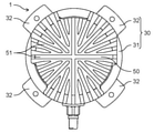
- FIG. 2 is a plan view of the motor according to the embodiment when viewed from the anti-output shaft side.
- FIG. 3 is a cross-sectional view taken along the line III-III of FIG.
- FIG. 4A is a diagram showing the relationship between the position angle of the rotor and the torque in the electric motor of the comparative example.
- FIG. 4B is a diagram showing the relationship between the position angle of the rotor and the torque in the electric motor of the embodiment.
- the radial direction of the stator 10 and the rotor 20 is the "diameter direction”
- the rotation direction of the rotor 20 is the "circumferential direction”. That is, the direction extending from the axis C around the axis C of the rotating shaft 21 is the "diameter direction”, and the direction rotating around the axis C around the axis C of the rotating shaft 21 is the "circumferential direction”. .. Therefore, the "diameter direction” is a direction orthogonal to the direction of the axis C of the rotating shaft 21.
- the rotor 20 rotates about the axis C of the rotating shaft 21 as the center of rotation.
- FIG. 1 is a half cross-sectional view of the electric motor 1 according to the embodiment.
- FIG. 2 is a plan view of the motor 1 when viewed from the anti-output shaft side.
- FIG. 3 is a cross-sectional view taken along the line III-III of FIG.
- the electric motor 1 includes a stator 10, a rotor 20 arranged facing the stator 10, and a mold resin 30 that covers the stator 10.
- the number of poles (number of magnetic poles) of the rotor 20 is 10.
- the slot 14 included in the stator 10 is 12. If the number of poles (number of magnetic poles) of the rotor 20 is 10 or more, the same effect can be expected.
- the motor 1 further includes a first bearing 41 and a second bearing 42, a heat sink 50, and a first bracket 61 and a second bracket 62.
- the electric motor 1 in the present embodiment is a mold motor in which the stator 10 is covered with the mold resin 30. Further, the electric motor 1 is a brushless motor that does not use a motor brush.
- the stator 10 (stator) is arranged to face the rotor 20 with a small air gap between the stator 10 and the stator 20.
- the stator 10 is arranged so as to surround the iron core 22 of the rotor 20. That is, the electric motor 1 is an inner rotor type motor in which the rotor 20 is arranged inside the stator 10.
- the stator 10 generates a magnetic force acting on the rotor 20.
- the stator 10 has a configuration in which a plurality of N poles and S poles are alternately and repeatedly present so as to generate a magnetic flux on the air gap surface between the rotor 20 and the iron core 22.
- the stator 10 and the rotor 20 form a magnetic circuit.
- the stator 10 has an iron core 11, a winding 12, and an insulator 13.
- the core 11 of the stator 10 is an annular stator core (stator core) that is the core of the stator 10, and generates a magnetic force for rotating the rotor 20.
- the iron core 11 is, for example, a laminated body in which a plurality of steel plates are laminated in the direction of the axis C of the rotating shaft 21 of the rotor 20.
- Each of the plurality of steel plates is, for example, a punched electrical steel plate formed into a predetermined shape.
- the iron core 11 is not limited to a laminated body of a plurality of steel plates, but may be a bulk body made of a magnetic material.
- the iron core 11 has a yoke 11a formed in an annular shape so as to surround the iron core 22 of the rotor 20, and a plurality of teeth 11b extending toward the rotor 20.
- the yoke 11a is a back yoke formed on the outside of each tooth 11b.
- the yoke 11a is formed in an annular shape centered on the axis C.
- the plurality of teeth 11b project from the yoke 11a toward the rotating shaft 21. Specifically, the plurality of teeth 11b extend radially in a direction (radial direction) orthogonal to the axis C of the rotation axis 21. The plurality of teeth 11b are arranged at equal intervals in the circumferential direction while forming slots 14 between two adjacent teeth 11b. That is, the slot 14 is located between the adjacent teeth 11b among the plurality of teeth 11b.
- the iron core 11 is provided with 12 teeth 11b, and the number of slots 14 is 12. That is, the number of slots of the motor 1 (stator 10) is 12.
- Each tooth 11b is provided with an extension portion extending from the tip end portion on the inner peripheral side of the tooth 11b to both sides in the circumferential direction.
- This stretched portion is formed so as to protrude from the tip portion on the inner peripheral side of the teeth 11b.
- the inner peripheral surface located at the tip end portion of the teeth 11b including the stretched portion serves as a magnetic pole surface facing the outer peripheral surface of the rotor 20.
- the winding 12 is an armature winding of the stator 10.
- the winding 12 is a winding coil wound around an iron core 11 as a stator coil (stator coil).
- the winding 12 is wound around each of the plurality of teeth 11b of the iron core 11. Specifically, the winding 12 is wound around each of the plurality of teeth 11b via the insulator 13. That is, a plurality of windings 12 are wound around the stator 10. Each winding 12 is a centralized winding coil wound around one corresponding tooth 11b and is housed in the slot 14 of the iron core 11.
- Each of the plurality of teeth 11b is a magnetic pole tooth, and a magnetic force is generated by energizing the winding 12.
- the plurality of windings 12 in the stator 10 are electrically connected as three-phase windings so that the rotor 20 rotates as a three-phase synchronous motor.
- the plurality of windings 12 are composed of unit coils of each of the three phases of U phase, V phase and W phase, which are electrically different in phase by 120 degrees from each other. That is, the winding 12 mounted on each tooth 11b is energized and driven by a three-phase alternating current that is energized in units of U phase, V phase, and W phase. As a result, the main magnetic flux of the stator 10 is generated in each tooth 11b.
- the twelve windings 12 wound around the twelve teeth 11b each have four U-phase coils, four V-phase coils, and four W-phase coils, depending on the phase of the current flowing through each winding 12. It is divided into and is arranged in a predetermined slot 14.
- the four U-phase coils are electrically connected so as to be connected in series.
- the four V-phase coils and the four W-phase coils are also electrically connected so as to be connected in series.
- the insulator 13 is a coil bobbin and has a frame-shaped frame portion around which the winding 12 is wound. Specifically, the frame portion of the insulator 13 is formed so as to surround the body portion of the teeth 11b. The insulator 13 is provided on each of the plurality of teeth 11b. Each insulator 13 is, for example, a resin molded product integrally formed of an insulating resin material.
- the rotor 20 (rotor) is rotated by the magnetic force generated in the stator 10.
- the rotor 20 also generates a magnetic force.
- the rotor 20 has a configuration in which a plurality of N poles and S poles that generate magnetic flux in the circumferential direction are alternately and repeatedly present.
- the rotor 20 generates a magnetic force acting on the stator 10.
- the direction of the magnetic flux generated from the rotor 20 is a direction orthogonal to the direction of the axis C of the rotation axis 21 (direction of the axis). That is, the direction of the magnetic flux generated by the rotor 20 is the radial direction (diameter direction).
- the rotor 20 has a rotating shaft 21, an iron core 22, a plurality of permanent magnets 23, and a dielectric 24.
- the rotor 20 rotates about the axis C of the rotating shaft 21 as the center of rotation. That is, the rotation shaft 21 becomes the center when the rotor 20 rotates.
- the rotor 20 is a permanent magnet embedded rotor (IPM rotor) in which the permanent magnet 23 is embedded in the iron core 22. Therefore, the electric motor 1 in the present embodiment is an IPM motor.
- IPM rotor permanent magnet embedded rotor
- the rotating shaft 21 has an axial center C which is the center when the rotor 20 rotates.
- the rotating shaft 21 extends in the direction of the axis C.
- the rotating shaft 21 is a long shaft, for example, a metal rod.
- the rotating shaft 21 is fixed to the iron core 22. Specifically, the rotating shaft 21 is inserted into a through hole provided in the center of the iron core 22 and fixed to the iron core 22 so as to extend on both sides of the iron core 22 along the direction of the axis C. ..
- the rotary shaft 21 is fixed to the iron core 22 by, for example, press-fitting or shrink-fitting into the through hole of the iron core 22.
- the first portion 21a which is one portion of the rotating shaft 21 protruding to one side of the iron core 22, is supported by the first bearing 41.
- the second portion 21b which is the other portion of the rotating shaft 21 protruding to the other side of the iron core 22, is supported by the second bearing 42. That is, the first bearing 41 and the second bearing 42 rotatably support the rotating shaft 21 as a pair of bearings. In this way, the rotating shaft 21 is held by the first bearing 41 and the second bearing 42 in a rotatable state. As a result, the rotor 20 is rotatable with respect to the stator 10.
- the first bearing 41 and the second bearing 42 are bearings.
- the first bearing 41 and the second bearing 42 are ball bearings, but may be other bearings such as thrust bearings.
- the end portion of the rotating shaft 21 at the first portion 21a is the end portion on the output side and protrudes from the first bracket 61 and the first bearing 41. That is, the first portion 21a of the rotating shaft 21 is an output shaft, and a load such as a rotating fan is attached to the end portion of the first portion 21a.
- the end of the rotating shaft 21 on the second portion 21b side is the end on the non-output side and does not protrude from the second bracket 62 and the second bearing 42.
- the second portion 21b of the rotating shaft 21 is a counter-output shaft.
- the iron core 22 of the rotor 20 is arranged via an air gap with the iron core 11 of the stator 10.
- the iron core 22 is a rotor core that is the core of the rotor 20.
- the iron core 22 is a laminated body in which a plurality of steel plates are laminated in the direction of the axis C of the rotating shaft 21.
- Each of the plurality of steel plates is, for example, a punched electrical steel plate formed into a predetermined shape.
- the plurality of steel plates are fixed to each other by, for example, caulking.
- the iron core 22 is not limited to a laminated body of a plurality of steel plates, but may be a bulk body made of a magnetic material.
- the iron core 22 has a plurality of magnet insertion holes 22a.
- Each of the plurality of magnet insertion holes 22a is a magnet embedding hole in which the permanent magnet 23 is embedded and arranged.
- the plurality of magnet insertion holes 22a are formed in the iron core 22 at equal intervals along the circumferential direction so as to surround the rotation shaft 21.
- Each of the plurality of magnet insertion holes 22a extends in the direction of the axis C of the rotating shaft 21.
- Permanent magnets 23 are arranged in each of the plurality of magnet insertion holes 22a. Specifically, one permanent magnet 23 is inserted in each magnet insertion hole 22a. Similar to the plurality of magnet insertion holes 22a, the plurality of permanent magnets 23 are arranged at equal intervals along the circumferential direction so as to surround the rotation shaft 21. Each permanent magnet 23 is a magnetized permanent magnet. The plurality of permanent magnets 23 are arranged so that the magnetic poles of the S pole and the N pole are alternately present in the circumferential direction of the rotor 20. That is, the directions of the magnetic poles of the S pole and the N pole of the two adjacent permanent magnets 23 are opposite to each other.
- the iron core 22 is provided with 10 magnet insertion holes 22a, 10 permanent magnets 23 are inserted into the iron core 22. Therefore, the number of poles of the rotor 20 is 10 (the logarithm of poles is 5).
- the permanent magnet 23 may be magnetized after being placed in the magnet insertion hole 22a, or the permanent magnet 23 may be magnetized in advance before being inserted into the magnet insertion hole 22a. However, considering the workability of inserting the permanent magnet 23 into the magnet insertion hole 22a, it is better to magnetize after inserting the permanent magnet 23 into the magnet insertion hole 22a.
- Each permanent magnet 23 has a plate shape.
- the permanent magnet 23 is a plate-shaped rectangular parallelepiped and has a rectangular shape in a plan view. Therefore, the cross-sectional shape of the permanent magnet 23 when cut in a plane having the axis C of the rotating shaft 21 as a perpendicular line is rectangular.
- Each permanent magnet 23 is arranged in the magnet insertion hole 22a so that the thickness direction is the radial direction of the iron core 22.
- Each permanent magnet 23 is arranged in the corresponding magnet insertion hole 22a toward the outer side (outer peripheral side) in the radial direction of the iron core 22.
- the permanent magnet 23 inserted in the magnet insertion hole 22a may be fixed to the iron core 22 with an adhesive, or a fixing member having a protrusion to be filled in the gap between the permanent magnet 23 and the magnet insertion hole 22a shall be separately provided.
- the permanent magnet 23 may be fixed to the iron core 22.
- the permanent magnet 23 is a rare earth magnet.
- the permanent magnet 23 is a neodymium rare earth magnet (Neodymium Magnet) containing neodymium, iron, and boron (Nd-Fe-B) as main components.
- the permanent magnet 23 is a sintered magnet, it may be a bonded magnet.
- the residual magnetic flux density of the permanent magnet 23 is preferably 1.33 T or more, more preferably 1.4 T or more.
- the coercive force (Hcj) of the permanent magnet decreases as the temperature rises.
- Dy dysprosium
- the coercive force of the permanent magnet 23 may be improved.
- the residual magnetic flux density (Br) of the rare earth magnet is lowered. Therefore, when dysprosium is added to the permanent magnet 23, the amount of dysprosium added may be small. In the present embodiment, the permanent magnet 23 does not contain dysprosium.
- the iron core 22 has a bulging portion 22c in which the corresponding positions of the plurality of permanent magnets 23 in the outermost peripheral portion bulge outward when viewed from the direction of the axis C of the rotating shaft 21. It becomes a shape. That is, the iron core 22 has a shape in which each bulging portion 22c becomes a petal when viewed from the direction of the axis C of the rotating shaft 21.
- the ten permanent magnets 23 are provided in the iron core 22, ten recesses 22b are formed in the outermost peripheral portion of the iron core 22.
- a bulging portion 22c is formed on the outermost peripheral portion of the iron core 22 so that a portion corresponding to the center of each of the magnetic poles of the 10 permanent magnets 23 bulges outward. That is, the rotor 20 is a petal rotor formed so that the iron core 22 has 10 petals.
- the outermost peripheral shape of the iron core 22 corresponding to each magnetic pole of the plurality of permanent magnets 23 includes a plurality of arcs having different radii. That is, in the bulging portion 22c (petal portion) corresponding to each permanent magnet 23, the outermost peripheral shape of the iron core 22 includes a plurality of arcs having different radii.
- the outermost peripheral shape of the iron core 22 in each bulging portion 22c includes a first arc and a second arc that are continuous through the inflection point. This inflection point is a connection point (boundary point) between the first arc and the second arc, and the first arc and the second arc form one continuous curve through the inflection point. ing.
- the first arc is an arc through which the first straight line (that is, the d-axis) passing through the center of the magnetic pole of the permanent magnet 23 and the axis C of the rotating shaft 21 passes through the first point where the outermost circumference of the iron core 22 intersects.
- the first arc is an arc that passes through the first point and connects two adjacent inflection points.
- the second straight line (that is, the q-axis) passing through the center between the magnetic poles of two adjacent permanent magnets 23 among the plurality of permanent magnets 23 and the axis C of the rotating shaft 21 is the outermost circumference of the iron core 22. It is an arc connecting the second point intersecting with and the turning point.
- the outermost peripheral shape of the iron core 22 in each bulging portion 22c is composed of one first arc and two second arcs. That is, the outermost peripheral shape of the iron core 22 corresponding to one magnetic pole of each permanent magnet 23 is composed of one first arc and two second arcs. Specifically, the outermost peripheral shape of the iron core 22 in each bulging portion 22c (one magnetic pole of each permanent magnet 23) has two inflection points, and one first arc has two second arcs. It is configured to be sandwiched between two arcs.
- the center of the first arc is the axis C of the rotating shaft 21. That is, assuming that the radius of the first arc is R1, the first arc is an arc having a radius R1 with the axis C as the center of rotation. Therefore, the first arc is a part of the circle forming the maximum diameter of the iron core 22.
- the center of the second arc is not located on the axis C of the rotating shaft 21, but is located between the axis C and the outermost circumference (outer edge) of the iron core 22.
- the second arc is an arc for forming the recess 22b by denting a part of the circle forming the maximum diameter of the iron core 22 toward the axis C. That is, by providing the second arc, a part of the outermost peripheral portion of the iron core 22 can be recessed.
- the center of the second arc is a point located on a line segment connecting the inflection point, which is the boundary point between the first arc and the second arc, and the axis C of the rotation axis 21. Is. That is, assuming that the radius of the second arc is R2, the second arc is an arc having a radius R2 with this point as the center of rotation.
- the dielectric 24 is provided between the rotating shaft 21 and the outer peripheral surface of the iron core 22. As shown in FIG. 3, when viewed from the direction of the axis C of the rotating shaft 21, the dielectric 24 is an annular shape surrounding the rotating shaft 21. Further, as shown in FIG. 1, the dielectric 24 extends in the direction of the axis C of the rotating shaft 21.
- the dielectric 24 is formed of an insulating material such as an insulating resin material. Therefore, the dielectric 24 insulates and separates the iron core 22 from the outer core and the inner core in series with the dielectric 24 as a boundary.
- thermosetting resin such as an unsaturated polyester resin or an epoxy resin
- thermoplastic resin such as polybutylene terephthalate or polyamide
- an elastic body such as an elastomer or a vulcanized rubber, or the like.
- the capacitance of the dielectric 24 is connected in series, and the impedance on the rotor 20 side can be increased. can.
- the potential difference between the inner ring and the outer ring in the first bearing 41 and the second bearing 42, that is, the shaft voltage can be lowered, so that electrolytic corrosion occurs in the first bearing 41 and the second bearing 42. Can be suppressed.
- the dielectric 24 is a polygonal ring around the rotating shaft 21 when viewed from the direction of the axis C of the rotating shaft 21.
- the number of angles and sides of the polygon of the dielectric 24 may be the same as the number of permanent magnets 23, so that the dielectric 24 is a regular pentagonal ring. In this way, by making the number of polygonal angles of the dielectric 24 equal to the number of magnetic poles of the permanent magnet 23 held by the rotor 20, the imbalance caused by the rotation of the rotor 20 is minimized. Can be limited.
- the apex of the polygonal corner of the dielectric 24 is located at the center of the pole magnetized by the permanent magnet 23 held by the rotor 20 around the rotation axis 21.
- the dielectric 24 can be arranged without obstructing the flow of the magnetic flux generated from the permanent magnet 23.
- the workability of the iron core 22 can be improved by rounding (R) the vertices of the polygonal corners of the dielectric 24.
- the stator 10 is covered with the mold resin 30.
- the mold resin 30 covers the outer portion of the stator 10 over the entire circumference in the circumferential direction of the stator 10. Specifically, the mold resin 30 covers the outer portions of the iron core 11, the winding 12, and the insulator 13. In the present embodiment, the mold resin 30 is in contact with the outer surfaces of the winding 12 and the insulator 13.
- the mold resin 30 is formed of an insulating resin material having excellent thermal conductivity, such as a polyester resin or an epoxy resin. Further, the mold resin 30 is formed of a thermosetting resin. In the present embodiment, the mold resin 30 is formed of unsaturated polyester which is a thermosetting resin. Specifically, the mold resin 30 is formed of a white BMC (Bulk Molding Compound) unsaturated polyester resin.
- the mold resin 30 constitutes the outer shell of the electric motor 1, and the outer surface of the mold resin 30 includes an exposed surface. Specifically, the outer peripheral surface which is the side surface of the mold resin 30 and the upper surface on the first bracket 61 side are exposed. Further, the mold resin 30 that covers the stator 10 constitutes a housing that includes the rotor 20. A printed circuit board to which the winding 12 of the stator 10 is connected may be arranged in this housing.
- the mold resin 30 has a main body portion 31 forming the body portion of the electric motor 1 and a protruding portion 32 provided on the main body portion 31.
- a plurality of protruding portions 32 are provided on the main body portion 31. Specifically, as shown in FIG. 2, four projecting portions 32 are provided at equal intervals along the circumferential direction.
- the main body portion 31 and the protruding portion 32 are integrally formed by molding to form one mold resin 30.
- the main body 31 covers the stator 10. Specifically, the main body 31 covers the iron core 11, the winding 12, and the insulator 13.
- the protruding portion 32 protrudes outward in the radial direction. Specifically, the protruding portion 32 protrudes outward from the side surface of the main body portion 31.
- the protruding portion 32 is a leg portion of the electric motor 1, and functions as a mounting portion for attaching the electric motor 1 to an external device or the like.
- the protrusion 32 is provided with a through hole for inserting a screw or the like.
- a heat sink 50 is arranged on one side of the mold resin 30 in the direction of the axis C of the rotating shaft 21. As shown in FIG. 2, the heat sink 50 has a plurality of fins 51.
- the heat sink 50 is made of, for example, aluminum, but may be made of a metal material other than aluminum.
- the first bracket 61 is fixed to one side of the mold resin 30 in the direction of the axis C of the rotating shaft 21.
- a second bracket 62 is fixed to the other end of the mold resin 30 in the direction of the axis C of the rotating shaft 21.
- the first bracket 61 holds the first bearing 41.
- the first bearing 41 is fixed to the recess of the first bracket 61.
- the second bracket 62 holds the second bearing 42.
- the second bearing 42 is fixed to the second bracket 62.
- the first bracket 61 and the second bracket 62 are made of, for example, a metal material such as iron.
- the first bracket 61 and the second bracket 62 are made of a metal plate having a constant thickness.
- the first bracket 61 and the second bracket 62 are fixed to the mold resin 30.
- a field current flows in the winding 12 to generate a magnetic field.
- a magnetic flux is generated from the stator 10 toward the rotor 20.
- a magnetic flux is generated from each of the teeth 11b of the iron core 11 of the stator 10 toward the iron core 22 of the rotor 20.
- a magnetic flux passing through the stator 10 is generated by a permanent magnet 23 embedded in the iron core 22.
- the magnetic force generated by the interaction between the magnetic flux generated by the stator 10 and the magnetic flux generated by the permanent magnet 23 of the rotor 20 becomes the torque for rotating the rotor 20, and the rotor 20 rotates.
- the motor 1 in the present embodiment is used for, for example, an air conditioner such as an air conditioner.
- the electric motor 1 is mounted on the compressor of the outdoor unit of the air conditioner as a fan motor in which a rotary fan is attached to the rotary shaft 21.
- a technique using a rare earth magnet having a high energy density is known as a permanent magnet of an IPM motor. Thereby, the output and efficiency of the IPM motor can be improved.
- an IPM motor the magnetic attraction force differs depending on the rotation position of the rotor due to the magnetic flux generated from the permanent magnet held in the iron core of the rotor, so that the torque called cogging torque is generated when the rotor rotates. Pulsation occurs. Therefore, when an IPM motor is used as a fan motor, vibration is generated by the cogging torque to generate noise, and the output and efficiency are lowered.
- the harmonic component of the drive current of the IPM motor will increase.
- the number of rotor poles is 10 or more, the harmonic component increases significantly. Therefore, in the conventional IPM motor using a rare earth magnet, the number of poles of the rotor has to be limited to 8 or less. Therefore, there is a limit to suppressing the vibration due to the cogging torque and suppressing the decrease in output and efficiency by increasing the number of poles of the rotor.
- a rare earth magnet having a high residual magnetic flux density (Br).
- a rare earth magnet having a high residual magnetic flux density for example, Br ⁇ 1.3T
- Vibration and noise will increase. Therefore, in a conventional fan motor equipped with an IPM motor using a rare earth magnet, a rare earth magnet (for example, Br ⁇ 1.3T) having a low residual magnetic flux density has to be used.
- the permanent magnet 23 arranged in the magnet insertion hole 22a of the iron core 22 of the rotor 20 has a residual magnetic flux density of 1.3 T or more (Br ⁇ 1.
- a 3T) rare earth magnet is used.
- the number of poles of the rotor 20 is set to 10 or more.
- the cogging torque can be suppressed, so that vibration and noise due to the cogging torque can be suppressed. That is, the increase in vibration and noise caused by using a rare earth magnet having a residual magnetic flux density of 1.3 T or more as the permanent magnet 23 is offset by increasing the number of poles of the rotor 20 to 10 or more. Can be done.
- the output and efficiency can be improved by setting the number of poles of the rotor 20 to 10 or more. That is, in addition to being able to improve the output and efficiency by using a rare earth magnet having a residual magnetic flux density of 1.3 T or more as the permanent magnet 23, it is possible to further improve the output and efficiency.
- the outermost peripheral shape of the iron core 22 corresponding to each magnetic pole of the plurality of permanent magnets 23 is configured to include a plurality of arcs having different radii. That is, the iron core 22 is configured to have a plurality of bulging portions 22c as petals when viewed from the direction of the axis C of the rotating shaft 21.
- the deviation of the magnetic flux density distribution from the ideal sinusoidal shape can be reduced, so that the induced voltage harmonic amplitude can be reduced in almost all orders. Therefore, the increase in the harmonic component due to the number of poles of the rotor 20 being 10 or more can be offset by forming the iron core 22 of the rotor 20 into a petal shape.
- the motor 1 although it is an IPM motor using a rare earth magnet, the harmonic component of the electric drive current is increased while achieving high output and high efficiency. While suppressing, the cogging torque can be suppressed and vibration and noise can also be suppressed. Therefore, even with an IPM motor using a rare earth magnet, it is possible to realize an electric motor 1 capable of suppressing vibration and noise and achieving both high output and high efficiency.
- the residual magnetic flux density of the permanent magnet 23, which is a rare earth magnet is preferably 1.4 T or more.
- the permanent magnet 23, which is a rare earth magnet, does not contain dysprosium.
- the residual magnetic flux density of the permanent magnet 23 can be improved as compared with the case where dysprosium is added to the permanent magnet 23, so that the output and efficiency of the motor 1 can be further improved.
- dysprosium is expensive and difficult to obtain, by not using dysprosium, it is possible to achieve both suppression of vibration and noise, high output, and high efficiency. And it can be easily manufactured.
- the motor 1 includes a mold resin 30 that covers the stator 10.
- the mold resin 30 may have a protruding portion 32 that protrudes outward from the side surface of the main body portion 31 that covers the stator 10.
- the natural frequency of the motor 1 can be increased, so that the vibration and noise of the motor 1 can be suppressed.
- the dielectric 24 is provided between the rotating shaft 21 and the outer peripheral surface of the iron core 22.
- the rotor 20 can have a double insulating structure and the impedance on the rotor 20 side can be increased.
- the potential difference (shaft voltage) between the inner ring and the outer ring in the first bearing 41 and the second bearing 42 can be lowered, so that electrolytic corrosion occurs in the first bearing 41 and the second bearing 42. Can be suppressed.
- FIG. 4A is a diagram showing the relationship between the position angle of the rotor and the torque in the electric motor of the comparative example.
- FIG. 4B is a diagram showing the relationship between the position angle of the rotor and the torque in the electric motor of the embodiment.
- the horizontal axis represents the mechanical angle A (deg) of the rotor
- the vertical axis represents the torque (unit: mN ⁇ m).
- the motor 1 according to the present embodiment shown in FIGS. 1 to 3 was used as the motor of the example.
- the electric motor of the embodiment is a 10-pole 12-slot (10P12S) IPM motor in which the number of poles of the rotor 20 is 10 and the number of slots of the stator 10 is 12.
- the permanent magnet 23 a neodymium rare earth magnet having a residual magnetic flux density (Br) of 1.41T was used.
- the cogging torque can be expected to be suppressed even if a neodymium rare earth magnet having a residual magnetic flux density of 1.5 T is used.
- the motor of the comparative example is an IPM motor of 8 poles and 12 slots (8P12S) having a structure in which the number of poles of the rotor 20 is changed to 8 poles in the motor 1 according to the present embodiment shown in FIGS. 1 to 3.
- a neodymium rare earth magnet having a residual magnetic flux density of 1.28 was used as the permanent magnet 23. Except for the number of poles of the rotor 20 and the residual magnetic flux density of the permanent magnet 23, the electric motor of the comparative example and the electric motor of the embodiment are the same.
- the maximum cogging torque width was 40.9 mN ⁇ m.
- the maximum cogging torque width of the electric motor (10P12S) of the embodiment was 20.9 mN ⁇ m.
- the electric motor 1 includes a rotor 20 having an iron core 22 to which a rotating shaft 21 extending in the axial direction is fixed, and a stator 10 arranged facing the rotor 20.
- the stator 10 has a plurality of teeth 11b extending toward the rotor 20 and slots 14 located between adjacent teeth 11b among the plurality of teeth 11b, and the iron core 22.
- the plurality of permanent magnets 23 are rare earth magnets, and the plurality of permanent magnets 23 have a plurality of permanent magnets 23.
- the outermost peripheral shape of the iron core 22 corresponding to each magnetic pole includes a plurality of arcs having different radii, the number of poles of the rotor 20 is 10 or more, and the residual magnetic flux density of the permanent magnet 23 is 1.3 T or more. be.
- the number of poles of the rotor is preferably 10, and the slot 14 of the stator 10 is preferably 12.
- the residual magnetic flux density of the permanent magnet 23 is preferably 1.4T or more.
- a mold resin 30 that covers the stator 10 may be provided.
- the mold resin 30 may have a main body portion 31 that covers the stator 10 and a protruding portion 32 that protrudes outward from the side surface of the main body portion 31.
- the rare earth magnet does not have to contain dysprosium.
- a bearing that rotatably supports the rotating shaft 21 may be provided, and a dielectric may be provided between the rotating shaft 21 and the outer peripheral surface of the iron core.
- the number of poles of the rotor 20 is 10 (that is, the number of permanent magnets 23 is 10), but the number is not limited to this. Any number can be applied as long as the number of poles of the rotor 20 is 10 or more.
- the number of slots of the stator 10 is 12, but the number is not limited to this. Any number can be applied to the number of slots of the stator 10.
- the winding 12 of the stator 10 is wound around the iron core 11 by centralized winding, but the present invention is not limited to this.
- the winding 12 of the stator 10 may be wound around the iron core 11 by distributed winding.
- the motor 1 in the above embodiment can be used for household electric equipment such as a vacuum cleaner or a refrigerator, or various electric equipment such as industrial electric equipment such as automobile equipment and robots.
- the electric motor according to the present disclosure can be widely used for equipment equipped with an electric motor in various fields such as a fan motor used for an air conditioner or the like.
Landscapes
- Engineering & Computer Science (AREA)
- Power Engineering (AREA)
- Iron Core Of Rotating Electric Machines (AREA)
- Permanent Field Magnets Of Synchronous Machinery (AREA)
Priority Applications (4)
| Application Number | Priority Date | Filing Date | Title |
|---|---|---|---|
| CN202180060754.4A CN116134707A (zh) | 2020-07-22 | 2021-06-30 | 电动机 |
| EP21845185.4A EP4187759A4 (en) | 2020-07-22 | 2021-06-30 | Electric motor |
| US18/004,624 US12542459B2 (en) | 2020-07-22 | 2021-06-30 | Electric motor |
| JP2022538665A JPWO2022019074A1 (https=) | 2020-07-22 | 2021-06-30 |
Applications Claiming Priority (2)
| Application Number | Priority Date | Filing Date | Title |
|---|---|---|---|
| JP2020125369 | 2020-07-22 | ||
| JP2020-125369 | 2020-07-22 |
Publications (1)
| Publication Number | Publication Date |
|---|---|
| WO2022019074A1 true WO2022019074A1 (ja) | 2022-01-27 |
Family
ID=79729424
Family Applications (1)
| Application Number | Title | Priority Date | Filing Date |
|---|---|---|---|
| PCT/JP2021/024801 Ceased WO2022019074A1 (ja) | 2020-07-22 | 2021-06-30 | 電動機 |
Country Status (5)
| Country | Link |
|---|---|
| US (1) | US12542459B2 (https=) |
| EP (1) | EP4187759A4 (https=) |
| JP (1) | JPWO2022019074A1 (https=) |
| CN (1) | CN116134707A (https=) |
| WO (1) | WO2022019074A1 (https=) |
Cited By (2)
| Publication number | Priority date | Publication date | Assignee | Title |
|---|---|---|---|---|
| JPWO2023203633A1 (https=) * | 2022-04-19 | 2023-10-26 | ||
| EP4485763A4 (en) * | 2022-02-24 | 2025-05-07 | Panasonic Intellectual Property Management Co., Ltd. | ROTOR AND ELECTRIC MOTOR |
Families Citing this family (4)
| Publication number | Priority date | Publication date | Assignee | Title |
|---|---|---|---|---|
| JP2020099121A (ja) * | 2018-12-17 | 2020-06-25 | 株式会社ミツバ | ロータ、モータ、及びワイパモータ |
| JP7010884B2 (ja) | 2019-05-15 | 2022-01-26 | 国立大学法人九州工業大学 | 希土類コバルト永久磁石及びその製造方法、並びにデバイス |
| JP7400597B2 (ja) * | 2020-03-31 | 2023-12-19 | 株式会社富士通ゼネラル | 電動機 |
| CN114844244A (zh) * | 2021-02-01 | 2022-08-02 | 宁波高悦电机技术有限公司 | 电机及电机定子 |
Citations (3)
| Publication number | Priority date | Publication date | Assignee | Title |
|---|---|---|---|---|
| WO2013054439A1 (ja) * | 2011-10-14 | 2013-04-18 | 三菱電機株式会社 | 永久磁石型モータ |
| JP5186899B2 (ja) | 2007-11-28 | 2013-04-24 | パナソニック株式会社 | ブラシレスモータ |
| JP2015223079A (ja) * | 2015-09-15 | 2015-12-10 | 信越化学工業株式会社 | 回転子及びスポーク型ipm永久磁石式回転機 |
Family Cites Families (16)
| Publication number | Priority date | Publication date | Assignee | Title |
|---|---|---|---|---|
| US8405270B2 (en) | 2007-05-07 | 2013-03-26 | Panasonic Corporation | Permanent magnet buried type electric motor |
| JP5161612B2 (ja) * | 2008-02-22 | 2013-03-13 | 株式会社東芝 | 永久磁石式回転電機、永久磁石式回転電機の組立方法及び永久磁石式回転電機の分解方法 |
| JP5413358B2 (ja) * | 2010-12-07 | 2014-02-12 | 株式会社安川電機 | 電動機 |
| EP2685611B1 (en) * | 2011-03-07 | 2016-05-25 | Panasonic Corporation | Motor and electrical appliance provided with same |
| JP5863410B2 (ja) | 2011-11-16 | 2016-02-16 | 信越化学工業株式会社 | 回転子及びスポーク型ipm永久磁石式回転機 |
| EP2800243B8 (en) | 2011-12-26 | 2018-02-28 | Mitsubishi Electric Corporation | Rotor of permanent-magnet embedded motor, and compressor, blower, and refrigerating/air conditioning device using the rotor |
| JP2013135542A (ja) * | 2011-12-27 | 2013-07-08 | Hitachi Ltd | 焼結磁石モータ |
| US20130270961A1 (en) * | 2012-04-16 | 2013-10-17 | Ming Tsung Chu | Internal permanent magnet motor |
| JP5288064B1 (ja) * | 2012-06-14 | 2013-09-11 | パナソニック株式会社 | モータ |
| JP6133350B2 (ja) | 2015-03-31 | 2017-05-24 | アイチエレック株式会社 | 永久磁石電動機および圧縮機 |
| US11637521B2 (en) * | 2016-10-31 | 2023-04-25 | Mitsubishi Electric Corporation | Driving device, air conditioner, and method for controlling compressor |
| JP2019208347A (ja) | 2018-05-30 | 2019-12-05 | 日立オートモティブシステムズ株式会社 | ロータコア、ロータ、回転電機、自動車用電動補機システム |
| JP6811222B2 (ja) * | 2018-09-28 | 2021-01-13 | ダイキン工業株式会社 | ロータ、モータ、及び圧縮機 |
| US11901772B2 (en) * | 2018-11-27 | 2024-02-13 | Mitsubishi Electric Corporation | Rotating electrical machine |
| CN110932511A (zh) * | 2019-11-26 | 2020-03-27 | 徐州鸿润达电动车有限公司 | 一种128型号12槽10极高功率永磁同步电机 |
| CN115088163A (zh) * | 2020-02-25 | 2022-09-20 | 三菱电机株式会社 | 送风机及空气调节装置 |
-
2021
- 2021-06-30 EP EP21845185.4A patent/EP4187759A4/en active Pending
- 2021-06-30 US US18/004,624 patent/US12542459B2/en active Active
- 2021-06-30 JP JP2022538665A patent/JPWO2022019074A1/ja active Pending
- 2021-06-30 CN CN202180060754.4A patent/CN116134707A/zh active Pending
- 2021-06-30 WO PCT/JP2021/024801 patent/WO2022019074A1/ja not_active Ceased
Patent Citations (3)
| Publication number | Priority date | Publication date | Assignee | Title |
|---|---|---|---|---|
| JP5186899B2 (ja) | 2007-11-28 | 2013-04-24 | パナソニック株式会社 | ブラシレスモータ |
| WO2013054439A1 (ja) * | 2011-10-14 | 2013-04-18 | 三菱電機株式会社 | 永久磁石型モータ |
| JP2015223079A (ja) * | 2015-09-15 | 2015-12-10 | 信越化学工業株式会社 | 回転子及びスポーク型ipm永久磁石式回転機 |
Cited By (3)
| Publication number | Priority date | Publication date | Assignee | Title |
|---|---|---|---|---|
| EP4485763A4 (en) * | 2022-02-24 | 2025-05-07 | Panasonic Intellectual Property Management Co., Ltd. | ROTOR AND ELECTRIC MOTOR |
| JPWO2023203633A1 (https=) * | 2022-04-19 | 2023-10-26 | ||
| WO2023203633A1 (ja) * | 2022-04-19 | 2023-10-26 | 三菱電機株式会社 | 固定子、電動機及び送風機 |
Also Published As
| Publication number | Publication date |
|---|---|
| US12542459B2 (en) | 2026-02-03 |
| EP4187759A4 (en) | 2024-01-03 |
| EP4187759A1 (en) | 2023-05-31 |
| JPWO2022019074A1 (https=) | 2022-01-27 |
| US20230253838A1 (en) | 2023-08-10 |
| CN116134707A (zh) | 2023-05-16 |
Similar Documents
| Publication | Publication Date | Title |
|---|---|---|
| US12542459B2 (en) | Electric motor | |
| CN109075681B (zh) | 电动机及空气调节机 | |
| JP6422595B2 (ja) | 電動機および空気調和機 | |
| JPWO2022019074A5 (https=) | ||
| CN109565195B (zh) | 换向极型转子、电动机以及空调机 | |
| KR20210011967A (ko) | 전동기, 송풍기 및 공기 조화 장치 | |
| US10784733B2 (en) | Motor and air conditioning apparatus | |
| JP6545393B2 (ja) | コンシクエントポール型の回転子、電動機および空気調和機 | |
| WO2023276514A1 (ja) | 回転子及びその製造方法、並びに電動機 | |
| US20230187984A1 (en) | Rotary electrical device | |
| EP4152568A1 (en) | Rotor and electric motor | |
| KR102189243B1 (ko) | 카트리지를 이용한 고정자 및 그를 포함하는 bldc 모터 | |
| CN117981205A (zh) | 转子的制造装置 | |
| TW202203549A (zh) | 旋轉電機 | |
| JP7850892B2 (ja) | 回転子及び電動機 | |
| CN104662778A (zh) | 径向间隙型旋转电机、送风机、压缩机和空调机 | |
| WO2026034079A1 (ja) | ロータおよびモータ | |
| WO2023162331A1 (ja) | ロータ及び電動機 | |
| JPWO2022219942A5 (https=) | ||
| WO2022219923A1 (ja) | 回転子及び電動機 | |
| WO2025204819A1 (ja) | ロータおよびモータ | |
| JPWO2022219923A5 (https=) | ||
| WO2022255038A1 (ja) | 回転子及び電動機 | |
| KR20200103964A (ko) | 카트리지를 이용한 고정자 및 그를 포함하는 bldc 모터 |
Legal Events
| Date | Code | Title | Description |
|---|---|---|---|
| 121 | Ep: the epo has been informed by wipo that ep was designated in this application |
Ref document number: 21845185 Country of ref document: EP Kind code of ref document: A1 |
|
| ENP | Entry into the national phase |
Ref document number: 2022538665 Country of ref document: JP Kind code of ref document: A |
|
| NENP | Non-entry into the national phase |
Ref country code: DE |
|
| ENP | Entry into the national phase |
Ref document number: 2021845185 Country of ref document: EP Effective date: 20230222 |
|
| WWG | Wipo information: grant in national office |
Ref document number: 18004624 Country of ref document: US |