WO2022019067A1 - 撮像機用加熱装置 - Google Patents
撮像機用加熱装置 Download PDFInfo
- Publication number
- WO2022019067A1 WO2022019067A1 PCT/JP2021/024685 JP2021024685W WO2022019067A1 WO 2022019067 A1 WO2022019067 A1 WO 2022019067A1 JP 2021024685 W JP2021024685 W JP 2021024685W WO 2022019067 A1 WO2022019067 A1 WO 2022019067A1
- Authority
- WO
- WIPO (PCT)
- Prior art keywords
- heating
- opening
- width
- imager
- plate
- Prior art date
- Legal status (The legal status is an assumption and is not a legal conclusion. Google has not performed a legal analysis and makes no representation as to the accuracy of the status listed.)
- Ceased
Links
Images

Classifications
-
- B—PERFORMING OPERATIONS; TRANSPORTING
- B60—VEHICLES IN GENERAL
- B60R—VEHICLES, VEHICLE FITTINGS, OR VEHICLE PARTS, NOT OTHERWISE PROVIDED FOR
- B60R11/00—Arrangements for holding or mounting articles, not otherwise provided for
- B60R11/04—Mounting of cameras operative during drive; Arrangement of controls thereof relative to the vehicle
-
- B—PERFORMING OPERATIONS; TRANSPORTING
- B60—VEHICLES IN GENERAL
- B60S—SERVICING, CLEANING, REPAIRING, SUPPORTING, LIFTING, OR MANOEUVRING OF VEHICLES, NOT OTHERWISE PROVIDED FOR
- B60S1/00—Cleaning of vehicles
- B60S1/02—Cleaning windscreens, windows or optical devices
-
- G—PHYSICS
- G02—OPTICS
- G02B—OPTICAL ELEMENTS, SYSTEMS OR APPARATUS
- G02B27/00—Optical systems or apparatus not provided for by any of the groups G02B1/00 - G02B26/00, G02B30/00
- G02B27/0006—Optical systems or apparatus not provided for by any of the groups G02B1/00 - G02B26/00, G02B30/00 with means to keep optical surfaces clean, e.g. by preventing or removing dirt, stains, contamination, condensation
-
- G—PHYSICS
- G03—PHOTOGRAPHY; CINEMATOGRAPHY; ANALOGOUS TECHNIQUES USING WAVES OTHER THAN OPTICAL WAVES; ELECTROGRAPHY; HOLOGRAPHY
- G03B—APPARATUS OR ARRANGEMENTS FOR TAKING PHOTOGRAPHS OR FOR PROJECTING OR VIEWING THEM; APPARATUS OR ARRANGEMENTS EMPLOYING ANALOGOUS TECHNIQUES USING WAVES OTHER THAN OPTICAL WAVES; ACCESSORIES THEREFOR
- G03B17/00—Details of cameras or camera bodies; Accessories therefor
- G03B17/55—Details of cameras or camera bodies; Accessories therefor with provision for heating or cooling, e.g. in aircraft
-
- H—ELECTRICITY
- H04—ELECTRIC COMMUNICATION TECHNIQUE
- H04N—PICTORIAL COMMUNICATION, e.g. TELEVISION
- H04N23/00—Cameras or camera modules comprising electronic image sensors; Control thereof
- H04N23/50—Constructional details
- H04N23/52—Elements optimising image sensor operation, e.g. for electromagnetic interference [EMI] protection or temperature control by heat transfer or cooling elements
-
- H—ELECTRICITY
- H05—ELECTRIC TECHNIQUES NOT OTHERWISE PROVIDED FOR
- H05B—ELECTRIC HEATING; ELECTRIC LIGHT SOURCES NOT OTHERWISE PROVIDED FOR; CIRCUIT ARRANGEMENTS FOR ELECTRIC LIGHT SOURCES, IN GENERAL
- H05B3/00—Ohmic-resistance heating
- H05B3/20—Heating elements having extended surface area substantially in a two-dimensional [2D] plane, e.g. plate-heater
- H05B3/22—Heating elements having extended surface area substantially in a two-dimensional [2D] plane, e.g. plate-heater non-flexible
- H05B3/26—Heating elements having extended surface area substantially in a two-dimensional [2D] plane, e.g. plate-heater non-flexible heating conductor mounted on insulating base
-
- H—ELECTRICITY
- H05—ELECTRIC TECHNIQUES NOT OTHERWISE PROVIDED FOR
- H05B—ELECTRIC HEATING; ELECTRIC LIGHT SOURCES NOT OTHERWISE PROVIDED FOR; CIRCUIT ARRANGEMENTS FOR ELECTRIC LIGHT SOURCES, IN GENERAL
- H05B3/00—Ohmic-resistance heating
- H05B3/84—Heating arrangements specially adapted for transparent or reflecting areas, e.g. for demisting or de-icing windows, mirrors or vehicle windshields
-
- B—PERFORMING OPERATIONS; TRANSPORTING
- B60—VEHICLES IN GENERAL
- B60R—VEHICLES, VEHICLE FITTINGS, OR VEHICLE PARTS, NOT OTHERWISE PROVIDED FOR
- B60R11/00—Arrangements for holding or mounting articles, not otherwise provided for
- B60R2011/0001—Arrangements for holding or mounting articles, not otherwise provided for characterised by position
- B60R2011/0003—Arrangements for holding or mounting articles, not otherwise provided for characterised by position inside the vehicle
- B60R2011/0026—Windows, e.g. windscreen
-
- G—PHYSICS
- G01—MEASURING; TESTING
- G01S—RADIO DIRECTION-FINDING; RADIO NAVIGATION; DETERMINING DISTANCE OR VELOCITY BY USE OF RADIO WAVES; LOCATING OR PRESENCE-DETECTING BY USE OF THE REFLECTION OR RERADIATION OF RADIO WAVES; ANALOGOUS ARRANGEMENTS USING OTHER WAVES
- G01S7/00—Details of systems according to groups G01S13/00, G01S15/00, G01S17/00
- G01S7/48—Details of systems according to groups G01S13/00, G01S15/00, G01S17/00 of systems according to group G01S17/00
- G01S7/481—Constructional features, e.g. arrangements of optical elements
- G01S7/4811—Constructional features, e.g. arrangements of optical elements common to transmitter and receiver
- G01S7/4813—Housing arrangements
Definitions
- the present disclosure relates to, for example, a heating device for an imager included in an imager mounted on a window glass of a vehicle.
- the light-shielding hood has a bottom wall portion and two side wall portions.
- the bottom wall portion has a substantially triangular shape that extends in the direction away from the camera unit in front of the camera unit.
- Each side wall portion has a shape that extends along a side extending in a direction away from the camera unit in the bottom wall portion and rises from the side.
- the heating portion has a shape that fits inside the bottom wall portion and is fixed to the back surface of the bottom wall portion.
- the heating device for an imager is configured to heat a part of the object to which the imager is attached, is located in front of the light receiving portion included in the camera unit, and is in a direction away from the light receiving portion. It is provided with an opening widened along the above opening and a heating portion having a sheet shape located on the side opposite to the mounting target with respect to the opening.
- the heating portion overlaps with at least a part of the opening when viewed from a viewpoint opposite to the opening with respect to the mounting target, and the opening in the portion of the opening where the heating portion overlaps. In the width direction in which the portion is expanded, the width of the heating portion is larger than the width of the opening.
- the heating device for an imager is a plate-shaped portion that is configured to heat a part of the mounting target of the imager and extends toward the front of the light receiving portion included in the camera unit.
- a plate-shaped portion having a size corresponding to the angle of view of the light receiving portion, and a heating portion having a sheet shape located on the side opposite to the mounting target with respect to the plate-shaped portion. ..
- the heating portion overlaps a part of the plate-shaped portion when viewed from a viewpoint opposite to the plate-shaped portion with respect to the mounting target, and in the portion of the plate-shaped portion where the heating portion overlaps, the heating portion overlaps.
- the width of the heating portion is larger than the width of the plate-shaped portion in the width direction in which the plate-shaped portion is expanded.
- the width of the heating portion 23 is larger than the width of the opening 22 in the width direction in which the opening 22 is expanded when viewed from the viewpoint opposite to the opening 22 with respect to the mounting target. Therefore, even if the position of the heating portion 23 with respect to the opening 22 is displaced in the width direction, if the displacement is within the difference between the size of the opening 22 and the size of the heating portion 23, the camera is included in the mounting target.
- the entire portion exposed to the opening 22 including the image pickup target of the unit 11 is the target of heating by the heating unit 23. That is, the displacement of the position of the heating portion 23 with respect to the opening 22 is allowed by the difference between the size of the opening 22 and the size of the heating portion 23. Therefore, it is possible to facilitate the attachment of the heating unit 23.
- the camera body 11A included in the camera unit 11 has an outer shape in which a substantially L-shaped cross-sectional shape is continuous along the left-right direction of the vehicle imager 10.
- the camera unit 11 includes a first right locking portion 11R1, a second right locking portion 11R2, a first left locking portion 11L1, and a second left locking portion 11L2.
- the pair of right locking portions 11R1 and 11R2 have columns protruding from the right side surface of the camera body 11A in the left-right direction.
- the pair of left locking portions 11L1 and 11L2 have columns protruding from the left side surface of the camera body 11A in the left-right direction.
- the pair of first locking portions 11R1, 11L1 extend along the same central axis.
- the pair of second locking portions 11R2, 11L2 extend along the same central axis at different positions from the pair of first locking portions 11R1, 11L1.
- the pair of second locking portions 11R2 and 11L2 are located in front of the pair of first locking portions 11R1 and 11L1.
- the heating device 12 includes a bracket 21.
- the bracket 21 is attached to the attachment target by an attachment member such as an adhesive member or a fastening member.
- the bracket 21 is a resin molded product formed of a synthetic resin.
- the bracket 21 includes a bracket main body 21A having a substantially rectangular plate shape.
- the bracket body 21A includes a front surface 21F and a back surface 21R opposite to the front surface 21F.
- the surface 21F of the bracket body 21A is arranged along the mounting target when the vehicle imager 10 is mounted on the mounting target.
- the bracket body 21A has a substantially V-shaped notch 21C at the front edge extending along the left-right direction.
- the right wall portion 21WR and the left wall portion 21WL extending downward are located in the notch 21C.
- the right wall portion 21WR and the left wall portion 21WL are examples of a pair of wall portions that sandwich the lens 11B and separate the opening 22 from the outside of the opening 22. Since a part of the light incident on the opening 22 from the outside of the opening 22 is blocked by the pair of wall portions 21WR and 21WL, it is possible to suppress excessive light from entering the opening 22. This makes it possible to suppress deterioration of image quality due to excessive light.
- the pair of wall portions 21WR and 21WL are central portions in the notch 21C and sandwich the portion of the camera unit 11 in which the lens 11B is arranged along the left-right direction.
- the right wall portion 21WR has a shape extending from the central portion of the notch 21C toward the right end of the notch 21C along the notch 21C.
- the left wall portion 21WL has a shape extending from the central portion of the notch 21C toward the left end of the notch 21C along the notch 21C.
- the substantially V-shaped region surrounded by the pair of wall portions 21WR and 21WL and located in front of the lens 11B is the opening 22 when viewed from the viewpoint facing the surface 21F of the bracket main body 21A. Is. Therefore, the width direction in which the opening 22 is widened is equal to the left-right direction.
- the bracket 21 includes a right locking leg 21LR and a left locking leg 21LL.
- the locking legs 21LR and 21LL are connected to the back surface 21R of the bracket main body 21A.
- the 21LL has a shape extending in the front-rear direction, and a part of each of the locking legs 21LR and 21LL is exposed from the notch 21C.
- the right locking leg 21LR has a first right locking groove (not shown) and a second right locking groove LR2.
- the left locking leg 21LL has a first left locking groove LL1 and a second left locking groove (not shown).
- the pair of first locking grooves are located on the same axis extending along the left-right direction.
- the pair of second locking grooves are located on the same axis extending along the left-right direction.
- the pair of second locking grooves LR2 is located in front of the pair of first locking grooves.
- the first right locking portion 11R1 fits into the first right locking groove, and the first left locking portion 11L1 fits into the first left locking groove LL1. .. Further, the second right locking portion 11R2 fits into the second right locking groove LR2, and the second left locking portion 11L2 fits into the second left locking groove. As a result, the bracket 21 supports the camera unit 11.
- the bracket 21 further includes a hood locking portion 21H.
- the hood locking portion 21H is connected to the back surface 21R of the bracket main body 21A.
- the cross section along the plane determined by the vertical direction and the horizontal direction has a substantially U-shape.
- the hood locking portion 21H has a shape in which the cross sections having a substantially U-shape are continuous in the front-rear direction.
- the bracket 21 has a hood locking groove (not shown).
- the hood locking groove is formed by the left locking leg 21LL and the bracket body 21A.
- the heating device 12 further includes a lens hood 24.
- the lens hood 24 is a resin molded product made of synthetic resin, similar to the bracket 21 described above.
- the lens hood 24 includes a hood body 24A, a right locking projection 24R, and a left locking projection 24L.
- the hood body 24A has a substantially trapezoidal shape. Of the pair of facing surfaces in the hood body 24A, the surface facing the heating portion 23 is the surface 24F.
- the surface 24F is a surface on which the heating unit 23 is arranged.
- the right locking projection 24R is located at the right end of the hood body 24A and has a shape extending in the front-rear direction.
- the left locking projection 24L is located at the left end of the hood body 24A and has a shape extending in the front-rear direction.
- the heating unit 23 includes a heat generating unit 23A and a supply unit 23B.
- the heat generating portion 23A has a substantially trapezoidal shape. In the left-right direction, the width of the heat generating portion 23A is substantially equal to the width of the hood body 24A. In the front-rear direction, the width of the heat generating portion 23A is substantially equal to the width of the hood body 24A.
- the target area to be heated by the heat generating portion 23A has substantially the same shape and size as the outer shape of the heat generating portion 23A. In the width direction, the width of the heating unit 23 is equal to the width of the heating unit 23A.
- the heating unit 23A may be, for example, a planar heating element.
- the heat generating portion 23A includes, for example, a good planar conductor, a current-carrying portion, and a pair of insulating films.
- the energizing unit is formed by one heating wire and is connected to the supply unit 23B.
- the energizing portion is sandwiched between a pair of insulating films.
- the good planar conductor is attached on one of the insulating films.
- the supply unit 23B is electrically connected to the heat generation unit 23A and supplies a current to the heat generation unit 23A.
- the supply unit 23B includes a protection circuit 23B1.
- the protection circuit 23B1 suppresses the magnitude of the current flowing through the planar heating element within a predetermined range.
- the protection circuit 23B1 includes a thermal fuse.
- the supply unit 23B is connected to the right end of the heat generation unit 23A and has a shape extending in the front-rear direction.
- the heat generating portion 23A is attached to the surface 24F of the hood body 24A by an adhesive, an adhesive or the like.
- the heating device 12 further includes a reflection suppression sheet 25.
- the reflection suppression sheet 25 has a substantially trapezoidal shape. In the left-right direction, the width of the reflection suppression sheet 25 is substantially equal to the width of the heat generating portion 23A. In the front-rear direction, the width of the reflection suppression sheet 25 is substantially equal to the width of the heat generating portion 23A.
- the reflection suppression sheet 25 covers the entire heat generating portion 23A.
- the reflection suppression sheet 25 is, for example, a resin film.
- the reflection suppression sheet 25 suppresses the reflection of light by, for example, absorbing the light incident on the reflection suppression sheet 25.
- the reflection suppression sheet 25 absorbs the light incident on the reflection suppression sheet 25, the reflection suppression sheet 25 exhibits, for example, black color.
- the reflection suppression sheet 25 is attached to the heating unit 23 with an adhesive, an adhesive, or the like.
- the lens 11B of the camera unit 11 is arranged between a pair of wall portions 21WR and 21WL in the left-right direction. As a result, the lens 11B is exposed to the opening 22.
- the lens 11B In the vehicle imager 10, only the light that can be incident on the region surrounded by the pair of wall portions 21WR and 21WL and the lens hood 24, that is, the opening portion 22, among the light incident on the vehicle interior through the mounting target. However, it is incident on the lens 11B.
- the light incident on the lens hood 24 is absorbed by the reflection suppression sheet 25 attached to the surface 24F of the lens hood 24 together with the heating unit 23. Therefore, since the light reflected by the lens hood 24 is hardly incident on the lens 11B, it is possible to prevent the quality of the image captured by the camera unit 11 from deteriorating.
- FIG. 3 shows the structure of the vehicle imager 10 as viewed from a viewpoint facing the surface of the bracket 21 in a state where the vehicle imager 10 is assembled. Note that in FIG. 3, for convenience of illustration, the camera unit 11 is not shown.
- the opening 22 is a pair of wall portions 21WR, 21WL and a pair of wall portions in the reflection suppression sheet 25. It is partitioned by a portion sandwiched by 21WR and 21WL. Therefore, since the heating unit 23 is covered with the reflection suppression sheet 25, it is possible to suppress the reflection of light in the heating unit 23, and thereby it is possible to suppress the deterioration of the image quality due to the reflection in the heating unit 23.
- the protection circuit 23B1 Since the protection circuit 23B1 is located outside the opening 22, the deterioration of image quality due to the protection circuit 23B1 facing the mounting target is suppressed as compared with the case where the protection circuit 23B1 is located inside the opening 22. be able to.
- the heating device 12 is also a structure including a plate-shaped portion and a heating portion.
- the plate-shaped portion spreads toward the front of the lens 11B included in the camera unit 11 and has a size corresponding to the angle of view ⁇ of the lens 11B.
- the heating portion 23 has a sheet shape located on the side opposite to the mounting target with respect to the plate-shaped portion. The heating portion 23 overlaps a part of the plate-shaped portion when viewed from the viewpoint opposite to the plate-shaped portion with respect to the mounting target, and in the portion of the plate-shaped portion where the heating portion 23 overlaps, the plate-shaped portion is formed. In the width direction to be expanded, the width of the heating portion 23 is larger than the width of the plate-shaped portion.
- the width of the heating portion 23 is larger than the width of the plate-shaped portion in the width direction in which the opening 22 is expanded when viewed from the viewpoint opposite to the plate-shaped portion with respect to the mounting target. Therefore, even if the position of the heating portion 23 is displaced with respect to the plate-shaped portion in the width direction, if the displacement is within the difference between the size of the plate-shaped portion and the size of the heating portion 23, the camera is included in the mounting target.
- the entire portion exposed to the plate-shaped portion including the image pickup target of the unit 11 is the target of heating by the heating unit 23. That is, the deviation of the position of the heating portion 23 with respect to the plate-shaped portion is allowed by the difference between the size of the plate-shaped portion and the size of the heating portion 23. Therefore, it is possible to facilitate the attachment of the heating unit 23.
- the range corresponding to the angle of view ⁇ is the range that overlaps with the angle of view ⁇ of the lens 11B when viewed from the viewpoint opposite to the plate-shaped portion with respect to the mounting target. In this embodiment, it is a region sandwiched by a pair of two-dot chain lines shown in FIG. That is, in the reflection suppression sheet 25, the portion sandwiched by the pair of two-dot chain lines is the plate-shaped portion.
- the reflection suppressing sheet 25 since a part of the reflection suppressing sheet 25 functions as a plate-shaped portion having a size corresponding to the angle of view ⁇ , the light reflected by the plate-shaped portion can be suppressed from being incident on the lens 11B. As a result, it is possible to prevent excessive light from being incident on the lens 11B.
- the heating unit 23 is covered with the reflection suppression sheet 25, it is possible to suppress the reflection of light in the heating unit 23, thereby suppressing the deterioration of image quality due to the reflection in the heating unit 23. ..
- the reflection suppression sheet 25 Since a part of the reflection suppression sheet 25 functions as a plate-shaped portion having a size corresponding to the angle of view ⁇ , the light reflected by the plate-shaped portion is suppressed from being incident on the lens 11B. As a result, it is possible to prevent excessive light from being incident on the lens 11B.
- the reflection suppression sheet 25 has a size corresponding to the angle of view ⁇
- the reflection suppression sheet 25 is a plate-shaped portion.
- the width of the heating portion 23 is larger than the width of the plate-shaped portion in the width direction when viewed from the viewpoint opposite to the reflection suppression sheet 25 with respect to the mounting target, and thus the above-mentioned (1). It is possible to obtain the same effect as above.
- the heating device 12 does not have to be provided with the reflection suppression sheet. Even in this case, in the portion of the opening 22 where the heating portion 23 overlaps, the width of the heating portion 23 is larger than the width of the opening 22 in the width direction in which the opening 22 is expanded. An effect according to (1) described above can be obtained.
- the protection circuit 23B1 may be located in the opening 22. Even in this case, when the heating device 12 includes the reflection suppression sheet 25, the protection circuit 23B1 is covered with the reflection suppression sheet 25, so that the deterioration of the image quality is suppressed.
- the lens hood 24 may have a recess recessed from the surface 24F of the lens hood 24, and the protection circuit 23B1 may be located in the recess.
- the depth of the recess is larger than the thickness of the protection circuit 23B1.
- the heating unit 23 may be located on the surface of the lens hood 24 opposite to the surface facing the mounting target. That is, the heating unit 23 may be located on the back surface of the lens hood 24 opposite to the front surface 24F. In this case, even if the protection circuit 23B1 is located in the opening 22, the protection circuit 23B1 is covered with the lens hood 24, so that deterioration of image quality due to the position of the protection circuit 23B1 can be suppressed. Further, in this case, even if the heating device 12 does not include the reflection suppression sheet 25, the reflection of light caused by the heating unit 23 does not occur.
- the heating unit 23 may overlap with the entire opening 22 when viewed from a viewpoint opposite to the opening 22 with respect to the mounting target. Also in this case, since the width of the heating portion 23 is larger than the width of the opening 22 in the width direction in which the opening 22 is expanded, the effect according to (1) described above can be obtained.
- the width of the heating portion 23 may be larger than the width of the opening 22 in the direction intersecting the width direction in which the opening 22 is expanded, in addition to the width direction in which the opening 22 is expanded.
- the width of the heating portion 23 may be larger than the width of the opening 22 in the front-rear direction. In this case, the displacement of the heating unit 23 with respect to the opening 22 is allowed by the difference between the width of the heating unit 23 and the width of the opening 22 in the front-rear direction.
- the heating device 12 may not be provided with the lens hood 24 for supporting the heating unit 23. Even in this case, the effect according to (1) described above can be obtained because the width of the heating portion 23 is larger than the width of the opening 22 in the width direction in which the opening 22 is expanded. ..
- the bracket body 21A does not have to be provided with the notch 21C. That is, the bracket body 21A may have a substantially rectangular shape when viewed from a viewpoint facing the surface 21F.
- the opening 22 is replaced with a pair of wall portions 21WR and 21WL, and the opening 22 is separated from the outside of the opening 22 by both ends in the left-right direction of the reflection suppression sheet 25.
- the width of the heating portion 23 is larger than the width of the opening 22 in the direction in which the opening 22 is widened, so that the effect according to (1) described above can be obtained. ..
- the camera unit 11 may include two or more lenses 11B.
- the heating device 12 may individually include an opening and a heating portion for each lens 11B, or may include an opening and a heating portion applied to a plurality of lenses 11B. Even in this case, the effect according to (1) described above can be obtained because the width of the heating portion 23 is larger than the width of the opening 22 in the width direction in which the opening 22 is expanded. ..
Landscapes
- Engineering & Computer Science (AREA)
- Physics & Mathematics (AREA)
- Mechanical Engineering (AREA)
- General Physics & Mathematics (AREA)
- Multimedia (AREA)
- Signal Processing (AREA)
- Electromagnetism (AREA)
- Aviation & Aerospace Engineering (AREA)
- Optics & Photonics (AREA)
- Studio Devices (AREA)
- Camera Bodies And Camera Details Or Accessories (AREA)
- Fittings On The Vehicle Exterior For Carrying Loads, And Devices For Holding Or Mounting Articles (AREA)
Abstract
撮像機用加熱装置は、撮像機の取付対象における一部を加熱するように構成され、カメラユニットが備える受光部の前方に位置し、受光部から離れる方向に沿って拡開された開口部と、開口部に対して取付対象とは反対側に位置してシート状を有した加熱部と、を備える。加熱部は、取付対象に対して開口部とは反対側の視点から見て、開口部の少なくとも一部と重なり、開口部のうちで加熱部が重なる部分では、開口部が拡開される幅方向において、加熱部の幅が開口部の幅よりも大きい。
Description
本開示は、例えば車両の窓ガラスに搭載される撮像機が備える撮像機用加熱装置に関する。
車両用の撮像機は、例えば、窓ガラスの一例であるウィンドシールドガラスが有する一対の面のうち、車室内側の面に取り付けられる。撮像機は、自車両の前方に位置する他車両および障害物の有無を検知するために用いられる。撮像機は、ウィンドシールドガラスに固定されるブラケット、ブラケットに支持されるカメラユニット、カメラユニットが受光する光の範囲を定める遮光フード、および、遮光フードの裏面に固定された加熱部を備えている。加熱部は、ウィンドシールドガラスのうちで、遮光フードに対向する部分を加熱することによって、当該部分に付着した結露による水滴、霜、および、氷などを消失させる。そのため、撮像機は、ウィンドシールドガラスを介してより鮮明な画像を撮像することが可能である(例えば、特許文献1を参照)。
ところで、遮光フードは、底壁部と2つの側壁部とを備えている。底壁部は、カメラユニットの前方において、カメラユニットから離れる方向に向かって広がる略三角形状を有している。各側壁部は、底壁部においてカメラユニットから離れる方向に沿って延びる辺に沿い、かつ、当該辺から立ち上がる形状を有している。加熱部は、底壁部内に収まる形状を有して、底壁部の裏面に固定されている。
上述したように、撮像機は、遮光フードによって定められた範囲の光を受光するから、撮像機は、ウィンドシールドのうちで、遮光フードに対向する部分を透過した光を受光する。一方、遮光フードの底壁部に対する加熱部の位置のずれは、ウィンドシールドのうちで、加熱部によって加熱される位置のずれを生じさせる。そのため、加熱部の位置のずれは、撮像機によって撮像される画像の鮮明さを低下させるおそれがあることから、底壁部に対する加熱部の位置には高い精度が求められる。加熱部の位置に要求される高い精度は、底壁部に対する加熱部の取り付けにおける難易度を高めるため、より容易に加熱部を取り付け可能であることが求められている。
本開示は、加熱部の取り付けを容易とすることを可能とした撮像機用加熱装置を提供することを目的とする。
本開示の一態様によれば、撮像機用加熱装置は、撮像機の取付対象における一部を加熱するように構成され、カメラユニットが備える受光部の前方に位置し、前記受光部から離れる方向に沿って拡開された開口部と、前記開口部に対して前記取付対象とは反対側に位置してシート状を有した加熱部と、を備える。前記加熱部は、前記取付対象に対して前記開口部とは反対側の視点から見て、前記開口部の少なくとも一部と重なり、前記開口部のうちで前記加熱部が重なる部分では、前記開口部が拡開される幅方向において、前記加熱部の幅が前記開口部の幅よりも大きい。
本開示の一態様によれば、撮像機用加熱装置は、撮像機の取付対象における一部を加熱するように構成され、カメラユニットが備える受光部の前方に向けて広がる板状部であって、前記受光部が有する画角に相応した大きさを有する前記板状部と、前記板状部に対して前記取付対象とは反対側に位置してシート状を有した加熱部と、を備える。前記加熱部は、前記取付対象に対して前記板状部とは反対側の視点から見て、前記板状部の一部と重なり、前記板状部のうちで前記加熱部が重なる部分では、前記板状部が拡開される幅方向において、前記加熱部の幅が前記板状部の幅よりも大きい。
図1から図3を参照して、撮像機用加熱装置の一実施形態を説明する。
図1が示す車両用撮像機10は、取付対象に取り付けられ、取付対象を介して入射する光を受光する。取付対象は、可視光を透過する光透過性を有した透明部材であり、例えば車両用の窓ガラスである。車両用撮像機10は、窓ガラスが備える一対の面のうち、車室内側の面に取り付けられる。窓ガラスは、例えばウィンドシールドガラスであるが、サンルーフガラス、および、リヤガラスなどであってもよい。車両用撮像機10は、カメラユニット11および加熱装置12を備えている。
図1が示す車両用撮像機10は、取付対象に取り付けられ、取付対象を介して入射する光を受光する。取付対象は、可視光を透過する光透過性を有した透明部材であり、例えば車両用の窓ガラスである。車両用撮像機10は、窓ガラスが備える一対の面のうち、車室内側の面に取り付けられる。窓ガラスは、例えばウィンドシールドガラスであるが、サンルーフガラス、および、リヤガラスなどであってもよい。車両用撮像機10は、カメラユニット11および加熱装置12を備えている。
カメラユニット11は、カメラ本体11Aと、受光部の一例であるレンズ11Bとを備えている。カメラ本体11Aは、例えば、撮像素子、記録素子、および、これらの素子を内蔵する筐体などを備えている。レンズ11Bは、カメラ本体11Aの外部に露出し、取付対象を介して入射した光を受光する。
加熱装置12は、車両用撮像機10が取付対象に取り付けられた状態において、車両用撮像機10の取付対象における一部を加熱する。加熱装置12は、開口部22と加熱部23とを備えている。開口部22は、カメラユニット11が備えるレンズ11Bの前方に位置し、レンズ11Bから離れる方向に沿って拡開されている。加熱部23は、開口部22に対して取付対象とは反対側に位置してシート状を有している。加熱部23は、取付対象に対して開口部22とは反対側の視点から見て、開口部22の少なくとも一部と重なり、開口部22のうちで加熱部23が重なる部分では、開口部22が拡開される幅方向において、加熱部23の幅が前記開口部の幅よりも大きい。
このように、取付対象に対して開口部22とは反対側の視点から見て、開口部22が拡開される幅方向において、加熱部23の幅が開口部22の幅よりも大きい。そのため、幅方向において開口部22に対する加熱部23の位置がずれたとしても、当該ずれが、開口部22の大きさと加熱部23の大きさとの差以内であれば、取付対象のうちで、カメラユニット11の撮像対象を含む開口部22に露出した部分の全体が加熱部23による加熱の対象である。すなわち、開口部22の大きさと加熱部23の大きさとの差の分だけ、開口部22に対する加熱部23の位置のずれが許容される。したがって、加熱部23の取り付けを容易とすることが可能である。
以下、車両用撮像機10が備える各部材について、図1を参照してより詳しく説明する。
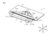
カメラユニット11が備えるカメラ本体11Aは、略L字状の断面形状が、車両用撮像機10の左右方向に沿って連なった外形を有している。カメラユニット11は、第1右係止部11R1、第2右係止部11R2、第1左係止部11L1、および、第2左係止部11L2を備えている。一対の右係止部11R1,11R2は、カメラ本体11Aの右側面から左右方向に沿って突き出た柱状を有している。一対の左係止部11L1,11L2は、カメラ本体11Aの左側面から左右方向に沿って突き出た柱状を有している。一対の第1係止部11R1,11L1は、同一の中心軸上に沿って延びている。一対の第2係止部11R2,11L2は、一対の第1係止部11R1,11L1とは異なる位置において、同一の中心軸に沿って延びている。一対の第2係止部11R2,11L2は、一対の第1係止部11R1,11L1よりも前方に位置している。
カメラユニット11が備えるカメラ本体11Aは、略L字状の断面形状が、車両用撮像機10の左右方向に沿って連なった外形を有している。カメラユニット11は、第1右係止部11R1、第2右係止部11R2、第1左係止部11L1、および、第2左係止部11L2を備えている。一対の右係止部11R1,11R2は、カメラ本体11Aの右側面から左右方向に沿って突き出た柱状を有している。一対の左係止部11L1,11L2は、カメラ本体11Aの左側面から左右方向に沿って突き出た柱状を有している。一対の第1係止部11R1,11L1は、同一の中心軸上に沿って延びている。一対の第2係止部11R2,11L2は、一対の第1係止部11R1,11L1とは異なる位置において、同一の中心軸に沿って延びている。一対の第2係止部11R2,11L2は、一対の第1係止部11R1,11L1よりも前方に位置している。
加熱装置12は、ブラケット21を備えている。ブラケット21は、接着部材や締結部材などの取付部材によって、取付対象に取り付けられる。ブラケット21は、合成樹脂によって形成された樹脂成形品である。ブラケット21は、略矩形板状を有したブラケット本体21Aを備えている。ブラケット本体21Aは、表面21Fと、表面21Fとは反対側の裏面21Rとを備えている。ブラケット本体21Aの表面21Fは、車両用撮像機10が取付対象に取り付けられた場合に、取付対象に沿って配置される。ブラケット本体21Aは、左右方向に沿って延びる前方の縁に、略V字状の切り欠き21Cを有している。
切り欠き21Cには、下方に向けて延びる右壁部21WRおよび左壁部21WLが位置している。右壁部21WRおよび左壁部21WLは、レンズ11Bを挟み、開口部22の外側から開口部22を区切る一対の壁部の一例である。開口部22の外側から開口部22内に入射する光の一部が一対の壁部21WR,21WLによって遮断されるため、開口部22内に過剰な光が入射することが抑えられる。これによって、過剰な光に起因した画像品質の低下を抑えることができる。
一対の壁部21WR,21WLは、切り欠き21Cにおける中央部であって、カメラユニット11のレンズ11Bが配置される部分を左右方向に沿って挟んでいる。右壁部21WRは、切り欠き21Cの中央部から切り欠き21Cの右端に向けて、切り欠き21Cに沿って延びる形状を有している。左壁部21WLは、切り欠き21Cの中央部から切り欠き21Cの左端に向けて、切り欠き21Cに沿って延びる形状を有している。本実施形態では、ブラケット本体21Aの表面21Fと対向する視点から見て、一対の壁部21WR,21WLによって囲まれ、かつ、レンズ11Bの前方に位置する略V字状の領域が、開口部22である。そのため、開口部22が拡開される幅方向は、左右方向に等しい。
ブラケット21は、右係止脚21LRと左係止脚21LLとを備えている。各係止脚21LR,21LLは、ブラケット本体21Aの裏面21Rに接続されている。各係止脚21LR.21LLは前後方向に沿って延びる形状を有し、各係止脚21LR,21LLの一部が、切り欠き21Cから露出している。
右係止脚21LRは、図示されない第1右係止溝と、第2右係止溝LR2とを有している。左係止脚21LLは、第1左係止溝LL1と、図示されない第2左係止溝とを有している。一対の第1係止溝は、左右方向に沿って延びる同一の軸上に位置している。一対の第2係止溝は、左右方向に沿って延びる同一の軸上に位置している。一対の第2係止溝LR2が、一対の第1係止溝よりも前方に位置している。
車両用撮像機10が組み立てられる際には、第1右係止部11R1が第1右係止溝に嵌まり、かつ、第1左係止部11L1が第1左係止溝LL1に嵌まる。また、第2右係止部11R2が第2右係止溝LR2に嵌まり、かつ、第2左係止部11L2が第2左係止溝に嵌まる。これにより、ブラケット21がカメラユニット11を支持する。
ブラケット21は、フード係止部21Hをさらに備えている。フード係止部21Hは、ブラケット本体21Aの裏面21Rに接続されている。フード係止部21Hにおいて、上下方向と左右方向とによって定まる平面に沿う断面が略コ字状を有している。フード係止部21Hは、当該略コ字状を有した断面が前後方向に沿って連なった形状を有している。
ブラケット21は、図示されないフード係止溝を有している。フード係止溝は、左係止脚21LLとブラケット本体21Aとによって形成される。
加熱装置12は、レンズフード24をさらに備えている。レンズフード24は、上述したブラケット21と同様、合成樹脂によって形成された樹脂成形品である。レンズフード24は、フード本体24A、右係止突起24R、および、左係止突起24Lを備えている。フード本体24Aは、略台形状を有している。フード本体24Aにおいて対向する一対の面のうち、加熱部23に対向する面が表面24Fである。表面24Fは、加熱部23が配置される面である。
加熱装置12は、レンズフード24をさらに備えている。レンズフード24は、上述したブラケット21と同様、合成樹脂によって形成された樹脂成形品である。レンズフード24は、フード本体24A、右係止突起24R、および、左係止突起24Lを備えている。フード本体24Aは、略台形状を有している。フード本体24Aにおいて対向する一対の面のうち、加熱部23に対向する面が表面24Fである。表面24Fは、加熱部23が配置される面である。
右係止突起24Rは、フード本体24Aの右端に位置し、前後方向に沿って延びる形状を有している。左係止突起24Lは、フード本体24Aの左端に位置し、前後方向に沿って延びる形状を有している。車両用撮像機10が組み立てられる際には、右係止突起24Rがフード係止部21Hに差し込まれ、かつ、左係止突起24Lがフード係止溝に差し込まれることによって、レンズフード24が、ブラケット21に支持される。このように、右係止突起24Rおよび左係止突起24Lは、ブラケット21との係合によって、フード本体24Aをブラケット21に係止する。
加熱部23は、発熱部23Aと供給部23Bとを備えている。発熱部23Aは、略台形状を有している。左右方向において、発熱部23Aが有する幅は、フード本体24Aが有する幅にほぼ等しい。前後方向において、発熱部23Aが有する幅は、フード本体24Aが有する幅にほぼ等しい。発熱部23Aが加熱する対象領域は、発熱部23Aの外形とほぼ同じ形状および大きさを有する。幅方向において、加熱部23の幅は発熱部23Aの幅に等しい。
発熱部23Aは、例えば面状発熱体であってよい。発熱部23Aは、例えば、面状良導体、通電部、および、一対の絶縁フィルムを備えている。通電部は、1本の発熱線によって形成され、供給部23Bに接続されている。通電部は、一対の絶縁フィルムによって挟まれている。面状良導体は、一方の絶縁フィルム上に貼り付けられている。
供給部23Bは、発熱部23Aに電気的に接続され、発熱部23Aに電流を供給する。供給部23Bは、保護回路23B1を備えている。保護回路23B1は、面状発熱体に流れる電流の大きさを、所定の範囲内に抑制する。保護回路23B1は、温度ヒューズを備えている。供給部23Bは、発熱部23Aの右端に接続され、前後方向に沿って延びる形状を有している。
発熱部23Aは、粘着剤および接着剤などによって、フード本体24Aの表面24Fに貼り付けられる。
加熱装置12は、反射抑制シート25をさらに備えている。反射抑制シート25は、略台形状を有している。左右方向において、反射抑制シート25が有する幅は、発熱部23Aが有する幅にほぼ等しい。前後方向において、反射抑制シート25が有する幅は、発熱部23Aが有する幅にほぼ等しい。反射抑制シート25は、発熱部23Aの全体を覆っている。
加熱装置12は、反射抑制シート25をさらに備えている。反射抑制シート25は、略台形状を有している。左右方向において、反射抑制シート25が有する幅は、発熱部23Aが有する幅にほぼ等しい。前後方向において、反射抑制シート25が有する幅は、発熱部23Aが有する幅にほぼ等しい。反射抑制シート25は、発熱部23Aの全体を覆っている。
反射抑制シート25は、例えば樹脂製のフィルムである。反射抑制シート25は、例えば、反射抑制シート25に入射した光を吸収することによって、光の反射を抑える。反射抑制シート25が反射抑制シート25に入射した光を吸収する場合には、反射抑制シート25は、例えば黒色を呈する。反射抑制シート25は、粘着剤および接着剤などによって、加熱部23に貼り付けられる。
図2は、車両用撮像機10が組み立てられた状態を示している。
図2が示すように、組み立てられた車両用撮像機10では、カメラユニット11が、ブラケット21が備える一対の係止脚21LR,21LLによって支持されている。車両用撮像機10では、加熱部23および反射抑制シート25が取り付けられたレンズフード24が、ブラケット21が備えるフード係止部21H、および、フード係止溝によって支持されている。
図2が示すように、組み立てられた車両用撮像機10では、カメラユニット11が、ブラケット21が備える一対の係止脚21LR,21LLによって支持されている。車両用撮像機10では、加熱部23および反射抑制シート25が取り付けられたレンズフード24が、ブラケット21が備えるフード係止部21H、および、フード係止溝によって支持されている。
車両用撮像機10において、カメラユニット11のレンズ11Bは、左右方向における一対の壁部21WR,21WLの間に配置される。これにより、レンズ11Bは、開口部22に露出する。車両用撮像機10では、取付対象を介して車室内に入射した光のうち、一対の壁部21WR,21WL、および、レンズフード24によって囲まれる領域、すなわち、開口部22に入射可能な光のみが、レンズ11Bに入射する。この際に、レンズフード24に向けて入射した光は、加熱部23とともにレンズフード24の表面24Fに取り付けられた反射抑制シート25によって吸収される。そのため、レンズ11Bには、レンズフード24において反射した光がほぼ入射しないから、カメラユニット11によって撮像される画像の品質が低下することが抑えられる。
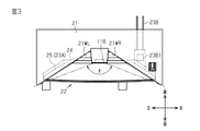
図3は、車両用撮像機10が組み立てられた状態において、ブラケット21の表面と対向する視点から見た車両用撮像機10の構造を示している。なお、図3では、図示の便宜上、カメラユニット11の図示が省略されている。
図3が示すように、取付対象に対して開口部22とは反対側の視点から見て、開口部22は、一対の壁部21WR,21WLと、反射抑制シート25のうちで一対の壁部21WR,21WLによって挟まれる部分によって区画される。そのため、加熱部23が反射抑制シート25によって覆われるため、加熱部23における光の反射を抑えることができ、これによって、加熱部23での反射に起因した画像品質の低下を抑えることができる。
取付対象に対して開口部22とは反対側の視点から見て、開口部22が拡開される左右方向において、発熱部23Aの幅が、開口部22の幅よりも大きい。そのため、発熱部23Aの右端に接続された供給部23Bは、取付対象に対して開口部22とは反対側の視点から見て、開口部22よりも外側に位置する。これにより、供給部23Bが備える保護回路23B1も開口部22よりも外側に位置する。言い換えれば、取付対象に対して開口部22とは反対側の視点から見て、保護回路23B1は、ブラケット21によって覆われている。
保護回路23B1が開口部22よりも外側に位置するため、保護回路23B1が開口部22内に位置する場合に比べて、保護回路23B1が取付対象に対向することに起因した画像品質の低下を抑えることができる。
なお、加熱装置12は、板状部と加熱部とを備える構造体でもある。板状部は、カメラユニット11が備えるレンズ11Bの前方に向けて広がり、レンズ11Bが有する画角θに相応した大きさを有している。加熱部23は、板状部に対して取付対象とは反対側に位置してシート状を有する。加熱部23は、取付対象に対して板状部とは反対側の視点から見て、板状部の一部と重なり、板状部のうちで加熱部23が重なる部分では、板状部が拡開される幅方向において、加熱部23の幅が板状部の幅よりも大きい。
取付対象に対して板状部とは反対側の視点から見て、開口部22が拡開される幅方向において、加熱部23の幅が板状部の幅よりも大きい。そのため、幅方向において板状部に対する加熱部23の位置がずれたとしても、当該ずれが、板状部の大きさと加熱部23の大きさとの差以内であれば、取付対象のうちで、カメラユニット11の撮像対象を含む板状部に露出した部分の全体が加熱部23による加熱の対象である。すなわち、板状部の大きさと加熱部23の大きさとの差の分だけ、板状部に対する加熱部23の位置のずれが許容される。したがって、加熱部23の取り付けを容易とすることが可能である。
画角θに相応する範囲は、取付対象に対して板状部とは反対側の視点から見て、レンズ11Bの画角θと重なる範囲である。本実施形態では、図3に示される一対の2点鎖線によって挟まれる領域である。すなわち、反射抑制シート25のうちで、一対の2点鎖線によって挟まれる部分が、板状部である。このように、反射抑制シート25の一部が画角θに相応した大きさを有する板状部として機能するから、板状部において反射した光がレンズ11Bに入射することが抑えられる。これによって、レンズ11Bに対して過剰な光が入射することが抑えられる。
以上説明したように、撮像機用加熱装置の一実施形態によれば、以下に記載の効果を得ることができる。
(1)開口部22の大きさと加熱部23の大きさとの差の分だけ、開口部22に対する加熱部23の位置のずれが許容される。したがって、加熱部23の取り付けを容易とすることが可能である。
(1)開口部22の大きさと加熱部23の大きさとの差の分だけ、開口部22に対する加熱部23の位置のずれが許容される。したがって、加熱部23の取り付けを容易とすることが可能である。
(2)開口部22の外側から開口部22内に入射する光の一部が一対の壁部21WR,21WLによって遮断されるため、開口部22内に過剰な光が入射することが抑えられる。これによって、過剰な光に起因した画像品質の低下を抑えることができる。
(3)加熱部23が反射抑制シート25によって覆われるため、加熱部23における光の反射を抑えることができ、これによって、加熱部23での反射に起因した画像品質の低下を抑えることができる。
(4)保護回路23B1が開口部22よりも外側に位置するため、保護回路23B1が開口部22内に位置する場合に比べて、保護回路23B1がレンズフード24における取付対象に対向することに起因した画像品質の低下を抑えることができる。
(5)板状部の大きさと加熱部23の大きさとの差の分だけ、板状部に対する加熱部23の位置のずれが許容される。したがって、加熱部23の取り付けを容易とすることが可能である。
(6)反射抑制シート25の一部が画角θに相応した大きさを有する板状部として機能するから、板状部において反射した光がレンズ11Bに入射することが抑えられる。これによって、レンズ11Bに対して過剰な光が入射することが抑えられる。
なお、上述した実施形態は、以下のように変更して実施することができる。
[反射抑制シート]
・反射抑制シート25が画角θに相応する大きさを有する場合には、反射抑制シート25が板状部である。この場合にも、取付対象に対して反射抑制シート25とは反対側の視点から見て、幅方向において、加熱部23の幅が板状部の幅よりも大きいことによって、上述した(1)に準じた効果を得ることはできる。
[反射抑制シート]
・反射抑制シート25が画角θに相応する大きさを有する場合には、反射抑制シート25が板状部である。この場合にも、取付対象に対して反射抑制シート25とは反対側の視点から見て、幅方向において、加熱部23の幅が板状部の幅よりも大きいことによって、上述した(1)に準じた効果を得ることはできる。
・反射抑制シート25は、光の吸収によってレンズフード24に入射した光の反射を抑えるシートに限らず、例えば、光の透過によってレンズフード24に入射した光の反射を抑えるシートであってもよい。光の透過によって光の反射を抑えるシートは、例えば、モスアイ構造を備えてもよい。これにより、レンズフード24に入射した光の反射を抑えられるから、上述した(3),(6)に準じた効果を得ることはできる。
・加熱装置12は、反射抑制シートを備えなくてもよい。この場合であっても、開口部22のうちで加熱部23が重なる部分では、開口部22の拡開される幅方向において、加熱部23の幅が開口部22の幅よりも大きいことによって、上述した(1)に準じた効果を得ることはできる。
[加熱部]
・保護回路23B1は、開口部22内に位置してもよい。この場合であっても、加熱装置12が反射抑制シート25を備える場合には、保護回路23B1が反射抑制シート25によって覆われることによって、画像品質の低下が抑えられる。
・保護回路23B1は、開口部22内に位置してもよい。この場合であっても、加熱装置12が反射抑制シート25を備える場合には、保護回路23B1が反射抑制シート25によって覆われることによって、画像品質の低下が抑えられる。
なお、保護回路23B1が開口部22内に位置する場合には、レンズフード24が、レンズフード24の表面24Fから窪む凹部を有し、当該凹部内に保護回路23B1が位置してもよい。この場合には、凹部の深さが、保護回路23B1が有する厚さよりも大きいことが好ましい。これにより、反射抑制シート25の一部が保護回路23B1に起因した凸状を有することが抑えられ、保護回路23B1に起因した凸状の部分が、撮影の妨げとなることが抑えられる。
・加熱部23は、レンズフード24のうちで、取付対象に対向する面とは反対側の面に位置してもよい。すなわち、加熱部23は、レンズフード24の表面24Fとは反対側の裏面に位置してもよい。この場合には、保護回路23B1が開口部22内に位置しても、保護回路23B1はレンズフード24に覆われるため、保護回路23B1の位置に起因した画像品質の低下は抑えられる。またこの場合には、加熱装置12が反射抑制シート25を備えなくとも、加熱部23に起因した光の反射は生じない。
・加熱部23は、取付対象に対して開口部22とは反対側の視点から見て、開口部22の全体と重なってもよい。この場合にも、開口部22が拡開される幅方向において、加熱部23の幅が開口部22の幅よりも大きいことによって、上述した(1)に準じた効果を得ることはできる。
・加熱部23の幅は、開口部22が拡開される幅方向に加えて、開口部22が拡開される幅方向と交差する方向において、開口部22の幅よりも大きくてもよい。例えば、上述した実施形態では、前後方向において、加熱部23の幅が開口部22の幅よりも大きくてもよい。この場合には、前後方向において、加熱部23の幅と開口部22の幅との差の分だけ、開口部22に対する加熱部23の位置ずれが許容される。
[レンズフード]
・加熱部23が十分に高い機械的な強度を有する場合には、加熱装置12は、加熱部23を支持するためのレンズフード24を備えなくてもよい。この場合であっても、開口部22が拡開される幅方向において、加熱部23の幅が開口部22の幅よりも大きいことによって、上述した(1)に準じた効果を得ることはできる。
・加熱部23が十分に高い機械的な強度を有する場合には、加熱装置12は、加熱部23を支持するためのレンズフード24を備えなくてもよい。この場合であっても、開口部22が拡開される幅方向において、加熱部23の幅が開口部22の幅よりも大きいことによって、上述した(1)に準じた効果を得ることはできる。
[ブラケット]
・ブラケット21は、一対の壁部21WR,21WLを備えなくてもよい。この場合には、開口部22は、レンズ11Bよりも前方の領域であって、かつ、ブラケット本体21Aが有する切り欠き21Cによって区画される略V字状を有した領域であってよい。この場合であっても、開口部22が拡開される幅方向において、加熱部23の幅が開口部22の幅よりも大きいことによって、上述した(1)に準じた効果を得ることはできる。
・ブラケット21は、一対の壁部21WR,21WLを備えなくてもよい。この場合には、開口部22は、レンズ11Bよりも前方の領域であって、かつ、ブラケット本体21Aが有する切り欠き21Cによって区画される略V字状を有した領域であってよい。この場合であっても、開口部22が拡開される幅方向において、加熱部23の幅が開口部22の幅よりも大きいことによって、上述した(1)に準じた効果を得ることはできる。
・ブラケット本体21Aは、切り欠き21Cを備えなくてもよい。すなわち、ブラケット本体21Aは、表面21Fと対向する視点から見て、略矩形状を有してもよい。この場合には、開口部22は、一対の壁部21WR,21WLに変えて、反射抑制シート25における左右方向の両端によって、開口部22は開口部22の外側から区切られる。そして、この場合には、開口部22が幅拡開される方向において、加熱部23の幅が開口部22の幅よりも大きいことによって、上述した(1)に準じた効果を得ることはできる。
[カメラユニット]
・カメラユニット11は、2つ以上のレンズ11Bを備えてもよい。この場合には、加熱装置12は、レンズ11Bごとに開口部および加熱部を個別に備えてもよいし、複数のレンズ11Bに対して適用される開口部および加熱部を備えてもよい。この場合であっても、開口部22が拡開される幅方向において、加熱部23の幅が開口部22の幅よりも大きいことによって、上述した(1)に準じた効果を得ることはできる。
・カメラユニット11は、2つ以上のレンズ11Bを備えてもよい。この場合には、加熱装置12は、レンズ11Bごとに開口部および加熱部を個別に備えてもよいし、複数のレンズ11Bに対して適用される開口部および加熱部を備えてもよい。この場合であっても、開口部22が拡開される幅方向において、加熱部23の幅が開口部22の幅よりも大きいことによって、上述した(1)に準じた効果を得ることはできる。
・カメラユニット11は、レンズ11B以外の受光部を備えてもよい。例えば、受光部は、被写体の像を投影することが可能な透過フィルムであってもよい。この場合であっても、開口部22が拡開される幅方向において、加熱部23の幅が開口部22の幅よりも大きいことによって、上述した(1)に準じた効果を得ることはできる。
Claims (6)
- 撮像機の取付対象における一部を加熱するように構成された撮像機用加熱装置であって、
カメラユニットが備える受光部の前方に位置し、前記受光部から離れる方向に沿って拡開された開口部と、
前記開口部に対して前記取付対象とは反対側に位置してシート状を有した加熱部と、を備え、
前記加熱部は、前記取付対象に対して前記開口部とは反対側の視点から見て、前記開口部の少なくとも一部と重なり、前記開口部のうちで前記加熱部が重なる部分では、前記開口部が拡開される幅方向において、前記加熱部の幅が前記開口部の幅よりも大きい
撮像機用加熱装置。 - 前記幅方向において、前記受光部を挟み、前記開口部の外側から前記開口部を区切る一対の壁部をさらに備える
請求項1に記載の撮像機用加熱装置。 - 前記加熱部は、保護回路を備え、
前記保護回路は、前記取付対象に対して前記開口部とは反対側の視点から見て、前記開口部よりも外側に位置する
請求項1または2に記載の撮像機用加熱装置。 - 可視光に対して前記加熱部よりも低い反射率を有し、前記加熱部を覆う反射抑制シートをさらに備える
請求項1から3のいずれか一項に記載の撮像機用加熱装置。 - 撮像機の取付対象における一部を加熱するように構成された撮像機用加熱装置であって、
カメラユニットが備える受光部の前方に向けて広がる板状部であって、前記受光部が有する画角に相応した大きさを有する前記板状部と、
前記板状部に対して前記取付対象とは反対側に位置してシート状を有した加熱部と、を備え、
前記加熱部は、前記取付対象に対して前記板状部とは反対側の視点から見て、前記板状部の一部と重なり、前記板状部のうちで前記加熱部が重なる部分では、前記板状部が拡開される幅方向において、前記加熱部の幅が前記板状部の幅よりも大きい
撮像機用加熱装置。 - 可視光に対して前記加熱部よりも低い反射率を有し、前記加熱部を覆う反射抑制シートをさらに備え、
前記板状部は、前記反射抑制シートの一部である
請求項5に記載の撮像機用加熱装置。
Priority Applications (2)
| Application Number | Priority Date | Filing Date | Title |
|---|---|---|---|
| US18/016,994 US20230284345A1 (en) | 2020-07-22 | 2021-06-30 | Heating device for imaging device |
| CN202180060179.8A CN116158083A (zh) | 2020-07-22 | 2021-06-30 | 摄像机用加热装置 |
Applications Claiming Priority (2)
| Application Number | Priority Date | Filing Date | Title |
|---|---|---|---|
| JP2020-125497 | 2020-07-22 | ||
| JP2020125497A JP7369677B2 (ja) | 2020-07-22 | 2020-07-22 | 撮像機用加熱装置 |
Publications (1)
| Publication Number | Publication Date |
|---|---|
| WO2022019067A1 true WO2022019067A1 (ja) | 2022-01-27 |
Family
ID=79729417
Family Applications (1)
| Application Number | Title | Priority Date | Filing Date |
|---|---|---|---|
| PCT/JP2021/024685 Ceased WO2022019067A1 (ja) | 2020-07-22 | 2021-06-30 | 撮像機用加熱装置 |
Country Status (4)
| Country | Link |
|---|---|
| US (1) | US20230284345A1 (ja) |
| JP (1) | JP7369677B2 (ja) |
| CN (1) | CN116158083A (ja) |
| WO (1) | WO2022019067A1 (ja) |
Cited By (1)
| Publication number | Priority date | Publication date | Assignee | Title |
|---|---|---|---|---|
| CN116552450A (zh) * | 2022-02-04 | 2023-08-08 | 本田技研工业株式会社 | 保持装置以及车辆 |
Families Citing this family (1)
| Publication number | Priority date | Publication date | Assignee | Title |
|---|---|---|---|---|
| JP7808494B2 (ja) * | 2022-03-17 | 2026-01-29 | 株式会社Subaru | 画像処理装置 |
Citations (3)
| Publication number | Priority date | Publication date | Assignee | Title |
|---|---|---|---|---|
| JP2018198375A (ja) * | 2017-05-23 | 2018-12-13 | 東京コスモス電機株式会社 | 発熱装置 |
| JP2019093794A (ja) * | 2017-11-20 | 2019-06-20 | 株式会社ニフコ | 加熱装置 |
| JP2020100213A (ja) * | 2018-12-20 | 2020-07-02 | 本田技研工業株式会社 | 移動体用撮影システム |
Family Cites Families (8)
| Publication number | Priority date | Publication date | Assignee | Title |
|---|---|---|---|---|
| JP6303974B2 (ja) * | 2014-10-22 | 2018-04-04 | 株式会社デンソー | 車載カメラ装置及び車載システム |
| JP6493087B2 (ja) * | 2015-08-24 | 2019-04-03 | 株式会社デンソー | 車載カメラ装置 |
| JP6589726B2 (ja) * | 2016-04-06 | 2019-10-16 | トヨタ自動車株式会社 | 車両用撮影装置 |
| JP7125261B2 (ja) * | 2017-12-12 | 2022-08-24 | 小島プレス工業株式会社 | 車両用撮影装置 |
| JP7006258B2 (ja) * | 2017-12-27 | 2022-01-24 | トヨタ自動車株式会社 | 車両用撮影装置及び加熱装置 |
| JP6702933B2 (ja) * | 2017-12-28 | 2020-06-03 | 株式会社ニフコ | 車両用ウインド装置の断熱構造 |
| JP7197587B2 (ja) * | 2018-07-27 | 2022-12-27 | 株式会社ニフコ | 面状発熱体、および、車両用ウインドシールド装置 |
| JP7172682B2 (ja) * | 2019-02-06 | 2022-11-16 | トヨタ自動車株式会社 | カメラ搭載構造 |
-
2020
- 2020-07-22 JP JP2020125497A patent/JP7369677B2/ja active Active
-
2021
- 2021-06-30 US US18/016,994 patent/US20230284345A1/en active Pending
- 2021-06-30 CN CN202180060179.8A patent/CN116158083A/zh active Pending
- 2021-06-30 WO PCT/JP2021/024685 patent/WO2022019067A1/ja not_active Ceased
Patent Citations (3)
| Publication number | Priority date | Publication date | Assignee | Title |
|---|---|---|---|---|
| JP2018198375A (ja) * | 2017-05-23 | 2018-12-13 | 東京コスモス電機株式会社 | 発熱装置 |
| JP2019093794A (ja) * | 2017-11-20 | 2019-06-20 | 株式会社ニフコ | 加熱装置 |
| JP2020100213A (ja) * | 2018-12-20 | 2020-07-02 | 本田技研工業株式会社 | 移動体用撮影システム |
Cited By (3)
| Publication number | Priority date | Publication date | Assignee | Title |
|---|---|---|---|---|
| CN116552450A (zh) * | 2022-02-04 | 2023-08-08 | 本田技研工业株式会社 | 保持装置以及车辆 |
| JP2023114295A (ja) * | 2022-02-04 | 2023-08-17 | 本田技研工業株式会社 | 保持装置および車両 |
| JP7345000B2 (ja) | 2022-02-04 | 2023-09-14 | 本田技研工業株式会社 | 保持装置および車両 |
Also Published As
| Publication number | Publication date |
|---|---|
| JP2022021725A (ja) | 2022-02-03 |
| US20230284345A1 (en) | 2023-09-07 |
| JP7369677B2 (ja) | 2023-10-26 |
| CN116158083A (zh) | 2023-05-23 |
Similar Documents
| Publication | Publication Date | Title |
|---|---|---|
| CN108696678B (zh) | 相机模块 | |
| US20180356634A1 (en) | Projection Device for a Head-Up Display, Head-Up Display, and Vehicle | |
| KR102123496B1 (ko) | 센서 탑재 구조 | |
| CN109969138B (zh) | 车辆用车窗装置的绝热结构 | |
| JP7369677B2 (ja) | 撮像機用加熱装置 | |
| JP7512046B2 (ja) | 取付装置 | |
| JP5488202B2 (ja) | 車載カメラ | |
| CA2171986C (en) | Multi-directional camera | |
| US20220295036A1 (en) | Vehicle body structure having camera | |
| KR20240167642A (ko) | 관통 베젤 적외선 조명을 갖는 풀 디스플레이 미러 어셈블리 | |
| JP7067422B2 (ja) | 車両用撮影装置 | |
| JP2022070434A (ja) | 撮像装置 | |
| JP7344853B2 (ja) | 撮像機用取付装置 | |
| WO2021182577A1 (ja) | 測距装置 | |
| JP4999386B2 (ja) | 後方カメラ付車両 | |
| CN223045643U (zh) | 车载前视摄像头总成和车辆 | |
| US20260029641A1 (en) | Inner mirror structure with built-in camera | |
| JP3259890B2 (ja) | 多方向撮像カメラ装置 | |
| JP3259889B2 (ja) | 多方向撮像カメラ装置 | |
| JP2023067565A (ja) | 車両周辺検出装置取付用ブラケット及び車両周辺検出装置取付構造 | |
| JPH1020369A (ja) | 多方向撮像カメラ装置 | |
| WO2025017204A1 (en) | Optical assembly | |
| JP2023119666A (ja) | 車載カメラ装置 | |
| JP2020152125A (ja) | 車両用撮影装置 | |
| CN116034054A (zh) | 摄像机用支撑装置以及摄像装置 |
Legal Events
| Date | Code | Title | Description |
|---|---|---|---|
| 121 | Ep: the epo has been informed by wipo that ep was designated in this application |
Ref document number: 21847398 Country of ref document: EP Kind code of ref document: A1 |
|
| NENP | Non-entry into the national phase |
Ref country code: DE |
|
| 122 | Ep: pct application non-entry in european phase |
Ref document number: 21847398 Country of ref document: EP Kind code of ref document: A1 |