WO2022019027A1 - 再構成たばこシートの製造装置および製造方法 - Google Patents
再構成たばこシートの製造装置および製造方法 Download PDFInfo
- Publication number
- WO2022019027A1 WO2022019027A1 PCT/JP2021/023574 JP2021023574W WO2022019027A1 WO 2022019027 A1 WO2022019027 A1 WO 2022019027A1 JP 2021023574 W JP2021023574 W JP 2021023574W WO 2022019027 A1 WO2022019027 A1 WO 2022019027A1
- Authority
- WO
- WIPO (PCT)
- Prior art keywords
- tobacco sheet
- reconstructed tobacco
- reconstructed
- die
- drum
- Prior art date
Links
Images


Classifications
-
- A—HUMAN NECESSITIES
- A24—TOBACCO; CIGARS; CIGARETTES; SIMULATED SMOKING DEVICES; SMOKERS' REQUISITES
- A24B—MANUFACTURE OR PREPARATION OF TOBACCO FOR SMOKING OR CHEWING; TOBACCO; SNUFF
- A24B3/00—Preparing tobacco in the factory
- A24B3/14—Forming reconstituted tobacco products, e.g. wrapper materials, sheets, imitation leaves, rods, cakes; Forms of such products
Definitions
- the present invention relates to a reconstructed tobacco sheet manufacturing apparatus and a manufacturing method.
- a rolling method, a cast (slurry) method, and a papermaking method are known as a method for manufacturing a reconstructed tobacco sheet. These production methods are selected according to the amount of water contained in the reconstituted tobacco raw material. In addition, each of these manufacturing methods is realized by different reconstructed tobacco sheet manufacturing devices.
- the rolling method is known to be particularly suitable for reconstituted tobacco raw materials containing 50% by volume or less of water.
- the kneaded product of the reconstituted tobacco raw material is rolled and molded by a rotating roller, the thickness is adjusted, and then the kneaded product is dried by a dryer provided separately.
- the cast (slurry) method is known to be particularly suitable for reconstituted tobacco raw materials containing 50% by volume or more of water.
- the fluid of the reconstituted tobacco raw material is continuously spread on a rotary drum or belt conveyor, leveled to a desired thickness with a member called a blade, and then the rotary drum or It is peeled off from the belt conveyor and dried by a separately provided dryer (see, for example, Patent Document 1).
- the papermaking method is known to be particularly suitable for reconstituted tobacco raw materials containing 80% by volume or more of water.
- the fluid of the reconstituted tobacco raw material is continuously spread on a liquid permeable belt conveyor, and after the water is removed by a squeezing roller and the desired thickness is obtained, a separately provided drying is performed. It is dried by the machine.
- An object of the present invention is to provide a reconstructed tobacco sheet manufacturing apparatus and a manufacturing method capable of obtaining a reconstructed tobacco sheet having a uniform thickness by a simple manufacturing process regardless of the amount of water contained in the reconstructed tobacco raw material. To provide.
- a reconstructed tobacco sheet manufacturing apparatus comprises a die for discharging the reconstructed tobacco raw material, and the die is formed on a housing, a supply port formed in the housing, and a supply port to which the reconstructed tobacco raw material is supplied, and one side surface of the housing. It has a discharge port for discharging the reconstituted tobacco raw material. According to this, it is possible to obtain a reconstructed tobacco sheet having a uniform thickness by a simple manufacturing process regardless of the amount of water contained in the reconstituted tobacco raw material.
- a plurality of dies are arranged along the longitudinal direction of the discharge port. According to this, the step of cutting the obtained reconstructed tobacco sheet to a desired width can be omitted.
- the die in the first form or the second form, has a variable width mechanism capable of changing the length of the discharge port in the width direction. According to this, it is possible to obtain a reconstructed tobacco sheet having a plurality of thicknesses without changing the die.
- the opening width of the discharge port so that the flow velocity of the reconstructed tobacco raw material at the discharge port of the die becomes uniform in the longitudinal direction of the discharge port, the occurrence of wrinkles is suppressed and the reconstructed tobacco sheet can be obtained. Can be molded flat.
- the die has a plurality of supply ports to which a plurality of raw materials are supplied, and the plurality of raw materials are laminated from the discharge port. And is discharged. According to this, the step of laminating a plurality of sheets can be omitted.
- the die has a partition portion for dividing the discharge port into a plurality of regions along the longitudinal direction of the discharge port. According to this, the step of stranding the sheet can be omitted.
- a method for manufacturing a reconstructed tobacco sheet includes a step of supplying the reconstituted tobacco raw material to the supply port of the die and a step of forming the reconstructed tobacco raw material into a sheet and discharging it from the discharge port of the die. According to this, it is possible to obtain a reconstructed tobacco sheet having a uniform thickness by a simple manufacturing process regardless of the amount of water contained in the reconstituted tobacco raw material.
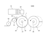
- FIG. 1 is a side view showing a reconstructed tobacco sheet manufacturing apparatus according to the first embodiment of the present invention.
- the reconstructed tobacco sheet manufacturing apparatus 100 includes an extruder 10, a die 20, a drum dryer (main drum) 30, a scraper 40, and rollers 51 and 52.
- the drum dryer 30 has a shaft 31 and a drum body 32.
- the extruder 10 pumps the reconstituted tobacco raw material supplied from a tank or the like (not shown) to the die 20.
- the die 20 discharges the reconstituted tobacco raw material supplied from the extruder 10, whereby the reconstituted tobacco raw material is formed on the drum body 32 of the drum dryer 30 as the reconstructed tobacco sheet 1.
- the drum dryer 30 dries and conveys the reconstructed tobacco sheet 1 formed on the drum main body 32.
- the scraper 40 peels the reconstructed tobacco sheet 1 dried by the drum dryer 30 from the drum body 32.
- the rollers 51 and 52 guide the transport of the reconstructed tobacco sheet 1 peeled off by the scraper 40.
- the reconstituted tobacco raw material is at least one substance selected from polysaccharides (starch, dextrin, etc.) and water or alcohol (ethanol, propylene glycol, etc.) or at least self-selected as a medium of any liquid.
- the reconstituted tobacco raw material is not limited to the above, and may contain other substances.
- FIG. 2 is a block diagram showing an extruder of the reconstructed tobacco sheet manufacturing apparatus according to the first embodiment of the present invention.
- FIG. 3 is a cross-sectional view taken along the line III-III shown in FIG.
- the extruder 10 is rotatably arranged in the housing 11, the supply port 12 formed at one end of the housing 11, the extrusion port 13 formed at the other end of the housing 11, and the housing 11. It has a screw 14.
- the reconstituted tobacco raw material supplied from the tank or the like to the extruder 10 via the supply port 12 is sent to the extrusion port 13 while being kneaded by the rotation of the screw 14, and is pressure-fed from the extrusion port 13 to the die 20.
- the discharge speed of the reconstructed tobacco sheet 1 discharged from the die 20 is determined according to the rotation speed of the screw 14.
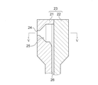
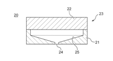
- FIG. 4 is a cross-sectional view showing a die of a reconstructed tobacco sheet manufacturing apparatus according to the first embodiment of the present invention.
- FIG. 5 is a cross-sectional view taken along the line VV shown in FIG.
- FIG. 6 is a side view of the die shown in FIG. 4 as viewed from the discharge port side.
- the die 20 is a housing 23 composed of a first block 21 and a second block 22, and a supply port 24 and a first block formed in the first block 21 and communicating with the extrusion port 13 of the extruder 10. It has a manifold 25 formed between the 21 and the second block 22 and in which the reconstituted tobacco raw material is stored, and a discharge port 26 communicating with the manifold 25.
- the discharge port 26 is formed in a slit shape on one side surface of the housing 23.
- the direction orthogonal to the longitudinal direction of the discharge port 26 is defined as the width direction of the discharge port 26.
- the length in the longitudinal direction of the discharge port 26 is referred to as an opening length
- the length in the width direction of the discharge port 26 is referred to as an opening width.
- the discharge port 26 may have a hole shape or a groove shape.
- the slit-shaped discharge port 26 adjusts the reconstituted tobacco raw material to a uniform thickness according to the opening width of the discharge port 26 when discharged from the die 20 regardless of the amount of water contained in the reconstructed tobacco raw material. , Formed into a sheet and extruded.
- the reconstituted tobacco raw material supplied from the extruder 10 to the die 20 via the supply port 24 is sent to the discharge port 26 through the manifold 25, and is discharged from the discharge port 26 as the reconstructed tobacco sheet 1 onto the drum body 32. Will be done.
- the drum dryer 30 has a shaft 31 and a drum body 32 that rotates about the shaft 31.
- the drum body 32 dries the reconstructed tobacco sheet 1 by, for example, steam sent into the drum body 32.
- the drum body 32 may be heated by a heater or the like.
- the scraper 40 is arranged so as to face the drum main body 32 over the entire length in the width direction of the drum main body 32 orthogonal to the rotation direction of the drum main body 32, and the tip portion thereof is adjusted so as to be in contact with or close to the drum main body 32. There is.
- the scraper 40 is arranged near the end of the drum body 32 on the downstream side in the rotation direction so that the reconstructed tobacco sheet 1 discharged on the upstream side in the rotation direction of the drum body 32 is sufficiently dried. There is.
- the reconstructed tobacco sheet 1 discharged onto the drum body 32 from the discharge port 26 of the die 20 is dried by the drum body 32 to which steam is sent into the inside, and the dried reconstructed tobacco sheet 1 is peeled off by the scraper 40. It is handed over to the subsequent process.
- the subsequent step is, for example, a step of cutting the reconstructed tobacco sheet 1 to a desired width, or a step of winding the cut reconstructed tobacco sheet onto a bobbin.
- the reconstructed tobacco sheet 1 comprises a step of supplying the reconstructed tobacco raw material to the supply port 24 of the die 20 and a step of forming the reconstructed tobacco raw material into a sheet from the discharge port 26 of the die 20 and discharging the reconstructed tobacco raw material.
- Manufactured by a manufacturing method that includes.
- the reconstructed tobacco sheet manufacturing apparatus includes a die for discharging the reconstructed tobacco raw material and a main drum for drying and transporting the reconstructed tobacco raw material discharged from the die.
- the die comprises a housing, a supply port formed in the housing to supply the reconstituted tobacco material, and a discharge port formed on one side of the housing to discharge the reconstituted tobacco material. Therefore, regardless of the amount of water contained in the reconstituted tobacco raw material, a reconstructed tobacco sheet having a uniform thickness can be obtained by a simple manufacturing process.
- FIG. 7 is a plan view showing a reconstructed tobacco sheet manufacturing apparatus according to a second embodiment of the present invention.
- the reconstructed tobacco sheet manufacturing apparatus 100A includes X extruders 10A to 10X and X dies 20A to 20X in place of the extruder 10 and die 20 shown in FIG.
- X may be 2 or more.
- X dies 20A to 20X may be connected to one extruder 10. Since other configurations are the same as those of the first embodiment described above, the description thereof will be omitted.
- Extruders 10A to 10X are connected to dies 20A to 20X, respectively. Further, the dies 20A to 20X are arranged along the longitudinal direction of the discharge port 26.
- the extruders 10A to 10X pump the reconstituted tobacco raw materials supplied from a tank or the like (not shown) to the dies 20A to 20X, respectively.
- the dies 20A to 20X discharge the reconstituted tobacco raw materials supplied from the extruders 10A to 10X onto the drum main body 32, respectively.
- the reconstructed tobacco in the above-mentioned latter step by adjusting the opening length of the discharge port 26 of the dies 20A to 20X to the width of the bobbin around which the reconstructed tobacco sheet 1 is wound in the above-mentioned subsequent step, the reconstructed tobacco in the above-mentioned latter step.
- the step of cutting the sheet 1 to a desired width becomes unnecessary.
- compositions of the reconstituted tobacco raw materials supplied to the extruders 10A to 10X different from each other, it is possible to manufacture a plurality of types of reconstructed tobacco sheets 1 with one drum dryer 30. Further, by selectively driving the set of the extruders 10A to 10X and the dies 20A to 20X, the manufacturing capacity of the reconstructed tobacco sheet manufacturing apparatus 100A can be easily adjusted.
- a plurality of dies are arranged along the longitudinal direction of the discharge port. Therefore, the step of cutting the obtained reconstructed tobacco sheet to a desired width can be omitted.
- the opening width of the discharge port 26 of the die 20 is constant, but in the reconstructed tobacco sheet manufacturing apparatus according to the third embodiment of the present invention, the die 20 has the opening width of the discharge port 26.
- the variable width mechanism is, for example, a screw.
- the variable width mechanism changes the opening width of the discharge port 26 by adjusting the gap between the first block 21 and the second block 22 shown in FIG. 6 according to the tightening amount of the screw.
- a plurality of screws may be provided so that the opening width of the discharge port 26 is different between the end portion and the center portion in the longitudinal direction of the discharge port 26. If the opening length of the discharge port 26 is larger than the opening width of the discharge port 26, the discharge state may differ in the longitudinal direction of the discharge port 26.
- the variable width mechanism may have an actuator such as a motor for driving a screw.
- the die has a variable width mechanism capable of changing the length in the width direction of the discharge port. Therefore, it is possible to obtain a reconstructed tobacco sheet having a plurality of thicknesses without changing the die.
- the opening width of the discharge port so that the flow velocity of the reconstructed tobacco raw material at the discharge port of the die becomes uniform in the longitudinal direction of the discharge port, the occurrence of wrinkles is suppressed and the reconstructed tobacco sheet can be obtained. Can be molded flat.
- FIG. 8 is a side view showing a reconstructed tobacco sheet manufacturing apparatus according to a fourth embodiment of the present invention.
- the reconstructed tobacco sheet manufacturing apparatus 100B includes three extruders 61 to 63 and a die 70 in place of the extruder 10 and the die 20 shown in FIG.
- the number of extruders is not limited to three, and may be two or more. Since other configurations are the same as those of the first embodiment described above, the description thereof will be omitted.
- the extruders 61 to 63 are connected to the die 70.
- Raw materials are supplied to the extruders 61 to 63 from tanks and the like (not shown). At least one of the raw materials supplied to the extruders 61-63 contains a reconstituted tobacco raw material. Further, the raw materials supplied to the extruders 61 to 63 may be different raw materials from each other or may contain the same raw materials.
- the extruders 61 to 63 pump the supplied raw material to the die 70 using a screw or the like (not shown).
- the die 70 has a plurality of supply ports 71 to 73 to which a plurality of raw materials are supplied from the extruders 61 to 63, and a discharge port 74 formed in a slit shape on one side surface of the die 70.
- the raw materials supplied from the extruders 61 to 63 via the supply ports 71 to 73 are spread by a manifold (not shown) and then merged in the vicinity of the discharge port 74 to form a laminated reconstructed tobacco sheet. 1 is discharged onto the drum body 32.
- the die 70 may have a plurality of raw materials merged in the manifold.
- the reconstructed tobacco sheet 1 having a simple structure and having a multi-layered structure can be obtained by omitting the sheet bonding step. Further, by forming the sheet in multiple layers before drying the reconstructed tobacco sheet 1 with the drum dryer 30, the adhesion of each layer can be strengthened. Furthermore, by inserting a sheet that suppresses stickiness into the multi-layered sheet, the reconstructed tobacco sheet 1 can be wound onto the bobbin and from the bobbin without taking measures such as dusting and release paper. The feeding can be easily performed.
- the die has a plurality of supply ports to which a plurality of raw materials are supplied, and the plurality of raw materials are laminated and discharged from the discharge port. Therefore, the step of laminating a plurality of sheets can be omitted.
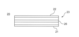
- FIG. 9 is a side view of the die of the reconstructed tobacco sheet manufacturing apparatus according to the fifth embodiment of the present invention as viewed from the discharge port side.
- the die 20 further has a partition 27 that divides the discharge port 26 into a plurality of regions along the longitudinal direction of the discharge port 26. That is, in FIG. 9, the slit-shaped discharge port 26 shown in FIG. 6 is intermittently opened. Since other configurations are the same as those of the first embodiment described above, the description thereof will be omitted.
- the reconstituted tobacco raw material supplied from the extruder 10 to the die 20 via the supply port 24 is sent to the discharge port 26 through the manifold 25, and is discharged from the discharge port 26 as the reconstructed tobacco sheet 1 onto the drum body 32. Will be done.
- the discharge port 26 is intermittently opened, the discharged reconstructed tobacco sheet 1 is already formed into a strip shape. Therefore, the reconstructed tobacco sheet 1 dried by the drum dryer 30 can be recovered as a strand as it is after the drying is completed.
- the die has a partition portion that divides the discharge port into a plurality of regions along the longitudinal direction of the discharge port. Therefore, the step of stranding the sheet can be omitted. Further, in the present invention, it is effective to use the die 20 having the partition portion 27 because the shape of the discharged reconstructed tobacco sheet is stable even before drying.
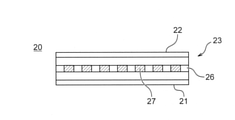
- FIG. 10 is a side view of the die of the reconstructed tobacco sheet manufacturing apparatus according to the sixth embodiment of the present invention as viewed from the discharge port side.
- the die 20 further has at least one raised portion 28 that faces the width direction of the discharge port 26 along the longitudinal direction of the discharge port 26.
- the cross-sectional shape of the raised portion 28 may be a triangle, a rectangle, a sinusoidal waveform, a T-shape, or the like. That is, in FIG. 10, the slit-shaped discharge port 26 shown in FIG. 6 is an opening having two widths, that is, the apex of the raised portion 28 or the side including the apex and the bottom of the raised portion 28. Since other configurations are the same as those of the first embodiment described above, the description thereof will be omitted.
- the reconstituted tobacco raw material supplied from the extruder 10 to the die 20 via the supply port 24 is sent to the discharge port 26 through the manifold 25, and is discharged from the discharge port 26 as the reconstructed tobacco sheet 1 onto the drum body 32. Will be done.
- the discharged reconstructed tobacco sheet 1 is already formed with strips having a cross-sectional shape corresponding to the raised portion 28. Therefore, the reconstructed tobacco sheet 1 dried by the drum dryer 30 can be recovered as the reconstructed tobacco sheet 1 in which the strips are formed as it is after the drying is completed.
- the die has at least one raised portion that faces the width direction of the discharge port along the longitudinal direction of the discharge port. Therefore, the reconstructed tobacco sheet can be reconstructed while omitting the step of passing the reconstructed tobacco sheet between the paired rollers and pressing the zigzag or corrugated shape, which has been performed with the conventional reconstructed tobacco sheet.
- Surface treatment eg, embossing
- FIG. 12 is a side view showing a reconstructed tobacco sheet manufacturing apparatus according to a seventh embodiment of the present invention.
- the reconstructed tobacco sheet manufacturing apparatus 100C includes a drum dryer (secondary drum) 35 and a scraper 45 in addition to the reconstructed tobacco sheet manufacturing apparatus 100 shown in FIG. Since other configurations are the same as those of the first embodiment described above, the description thereof will be omitted.
- the drum dryer 35 is arranged after the drum dryer 30 and is used in combination with the drum dryer 30.
- the drum dryer 35 has a shaft 36 and a drum body 37 that rotates about the shaft 36.
- the drum body 37 is heated, for example, by steam sent into the drum body 37.
- the drum body 37 may be heated by a heater or the like. Further, the drum dryer 30 and the drum dryer 35 are configured so that the temperature can be adjusted independently.
- the drum dryer 35 receives the reconstructed tobacco sheet 1 dried by the drum dryer 30 and peeled off by the scraper 40, and further dries and conveys the reconstructed tobacco sheet 1.
- the scraper 45 peels the reconstructed tobacco sheet 1 dried by the drum dryer 35 from the drum body 37.
- the drying distance of the reconstructed tobacco sheet 1 can be extended, and the drying capacity of the reconstructed tobacco sheet manufacturing apparatus 100C can be improved. Therefore, it is possible to cope with a reconstituted tobacco raw material having a large amount of water.
- the respective drum diameters are set to 1. It can be halved the drum diameter of one drum dryer. That is, the total volume of the two drum dryers can be reduced to half that of one drum dryer. Therefore, when two drum dryers are used, the required heat energy can be reduced to half that when one drum dryer is used.
- the sub-drum used in combination with the main drum is further provided, and the sub-drum is arranged after the main drum, and the reconstructed tobacco raw material conveyed by the main drum is used. Receive from the main drum and carry it further. Therefore, the reconstituted tobacco raw material dried and transported by the main drum can be further treated while extending the transport distance of the reconstituted tobacco raw material.
- the sub-drum is a drum dryer, but the sub-drum is not limited to this, and the sub-drum may be a cooling drum for cooling the reconstructed tobacco sheet 1 dried by the drum dryer 30.
- FIG. 13 is a side view showing a reconstructed tobacco sheet manufacturing apparatus according to an eighth embodiment of the present invention.
- the reconstructed tobacco sheet manufacturing apparatus 100D includes a drum dryer (secondary drum) 35 in addition to the reconstructed tobacco sheet manufacturing apparatus 100 shown in FIG. Since other configurations are the same as those of the first embodiment described above, the description thereof will be omitted.
- the drum dryer 35 is arranged to face the drum dryer 30 and is used in combination with the drum dryer 30.
- the drum dryer 35 has a shaft 36 and a drum body 37 that rotates about the shaft 36.
- the shaft 36 is configured so that the gap between the drum dryer 30 and the drum dryer 35 can be arbitrarily adjusted by a drive mechanism (not shown).
- the drum body 37 is heated by, for example, steam sent into the drum body 37.
- the drum body 37 may be heated by a heater or the like.
- the drum dryer 30 and the drum dryer 35 are configured so that the temperature can be adjusted independently.
- the drum dryer 35 dries and conveys the reconstructed tobacco sheet 1 formed on the drum body 32 in cooperation with the drum dryer 30.
- the reconstructed tobacco sheet 1 conveyed by the drum dryer 30 and the drum dryer 35 is compressed as it passes through the gap between the drum dryer 30 and the drum dryer 35.
- the density of the reconstructed tobacco sheet 1 is reduced by the compaction effect of the drum dryer 30 and the drum dryer 35 at the time of ejection from the die 20. Can be enhanced. Further, by adjusting the gap between the drum dryer 30 and the drum dryer 35, it is possible to control the thickness of the reconstructed tobacco sheet 1 that has passed through the gap between the drum dryer 30 and the drum dryer 35.
- the compaction effect of the drum dryer 30 and the drum dryer 35 causes the reconstructed tobacco according to the distribution of the ejection speed at the time of ejection from the die 20. Wrinkles and the like generated on the sheet 1 can be eliminated.
- embossing the surface of the drum body 37 when the reconstructed tobacco sheet 1 passes through the gap between the drum dryer 30 and the drum dryer 35, the surface of the reconstructed tobacco sheet 1 is embossed. And the specific surface area can be expanded.
- the processing performed on the surface of the drum body 37 is not limited to the embossing processing, and may be slit processing or the like for cutting the reconstructed tobacco sheet 1.
- the sub-drum used in combination with the main drum is further provided, and the sub-drum is arranged to face the main drum and is discharged from the die in cooperation with the main drum. Transport the reconstituted tobacco raw material. Therefore, in cooperation with the main drum, the reconstituted tobacco raw material dried and transported by the main drum can be further treated.
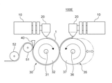
- FIG. 14 is a side view showing a reconstructed tobacco sheet manufacturing apparatus according to a ninth embodiment of the present invention.
- the reconstructed tobacco sheet manufacturing apparatus 100E includes an extruder 10 and a die 20 provided in the drum dryer 35 in addition to the reconstructed tobacco sheet manufacturing apparatus 100D shown in FIG. Since other configurations are the same as those of the eighth embodiment described above, the description thereof will be omitted.
- the extruder 10 provided in the drum dryer 35 is supplied with raw materials supplied from a tank or the like (not shown).
- the raw material supplied to the extruder 10 may or may not contain the reconstituted tobacco raw material.
- the extruder 10 pumps the supplied raw material to the die 20 using a screw or the like (not shown).
- the die 20 provided in the drum dryer 35 forms the raw material supplied from the extruder 10 into a sheet shape and discharges the raw material onto the drum main body 37.
- the sheets discharged from each of the die 20 provided in the drum dryer 30 and the die 20 provided in the drum dryer 35 are multi-layered when passing through the gap between the drum dryer 30 and the drum dryer 35.
- the sheets having different characteristics are bonded by passing the sheets discharged from the dies 20 provided in the drum dryer 30 and the drum dryer 35 through the gap between the drum dryer 30 and the drum dryer 35.
- the adhesion of each layer can be strengthened by making the sheets multi-layered before drying the tobacco sheet 1 reconstructed by the drum dryer 30 and the drum dryer 35. Further, by adjusting the gap between the drum dryer 30 and the drum dryer 35, it is possible to control the thickness of the reconstructed tobacco sheet 1 that has passed through the gap between the drum dryer 30 and the drum dryer 35.
- the sub-drum used in combination with the main drum and the die having the same configuration as the die provided on the main drum and discharging the discharge material to the sub-drum. Further prepare. Therefore, the step of laminating a plurality of sheets can be omitted.
- Tenth embodiment In the reconstructed tobacco sheet manufacturing apparatus according to the tenth embodiment of the present invention, the characteristics of the surface of the drum body 32 of the drum dryer 30 and the drum body 37 of the drum dryer 35 shown in the first embodiment and the like are obtained. Surface modification treatment is applied for improvement.
- the improvement of the characteristics is the improvement of wear resistance, corrosion resistance, peeling / releasability, and thermal conductivity
- the surface modification treatment is a chemical treatment such as plating or a physical treatment such as blasting. including. Examples of specific characteristics and surface modification treatment are shown in Tables 1 to 6. As a result, the surface characteristics of the drum body 32 of the drum dryer 30 and the drum body 37 of the drum dryer 35 are improved, and the usability and durability of the device can be improved.
- ⁇ indicates that it can be applied as a surface treatment regardless of the conditions of the extruded material or the apparatus. Further, in Tables 1 to 6, ⁇ indicates that it can be applied as a surface treatment if either the extruded material or the conditions of the apparatus are met. Further, in Tables 1 to 6, ⁇ indicates that it can be applied as a surface treatment if both the conditions of the extruded material and the apparatus are met.
- the main drum is subjected to surface modification treatment. Therefore, the characteristics of the surface of the main drum can be improved.
- the surface modification treatment may be applied to the sub drum, not limited to the main drum.
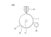
- FIG. 15 is a side view showing a reconstructed tobacco sheet manufacturing apparatus according to the eleventh embodiment of the present invention.
- the reconstructed tobacco sheet manufacturing apparatus 100F includes a hot air blower (auxiliary drying apparatus) 80 in addition to the reconstructed tobacco sheet manufacturing apparatus 100 shown in FIG. Since other configurations are the same as those of the first embodiment described above, the description thereof will be omitted.
- the hot air blower 80 is arranged on the drying path of the drum dryer 30 so as to face the drum main body 32 of the drum dryer 30.
- the hot air blower 80 sends hot air to dry the reconstructed tobacco sheet 1 discharged onto the drum body 32 from the discharge port 26 of the die 20 from the surface side of the reconstructed tobacco sheet 1.
- the surface of the reconstructed tobacco sheet 1 is a surface that is not in contact with the drum body 32 of the reconstructed tobacco sheet 1.
- the hot air blower 80 is configured so that the drying capacity can be adjusted by unique parameters such as air volume, output, and hot air temperature. Further, the hot air temperature can be set to a temperature equal to or higher than normal temperature.
- the drying capacity of the reconstructed tobacco sheet manufacturing apparatus 100F can be improved. Therefore, with a simple structure, it is possible to cope with a reconstituted tobacco raw material having a large amount of water. Further, by using the hot air blower 80, both sides of the reconstructed tobacco sheet 1 can be dried at the same time.
- an auxiliary drying device is further provided, which is arranged to face the main drum and dries the reconstituted tobacco raw material discharged from the die. Therefore, the drying capacity of the reconstructed tobacco sheet manufacturing apparatus can be improved.
- the auxiliary drying device is a hot air blower, but the present invention is not limited to this, and the auxiliary drying device may be an IR heater. Further, instead of the auxiliary drying device, a cooling device that sends cold air to the reconstructed tobacco sheet 1 may be provided.
- FIG. 16 is a side view showing a reconstructed tobacco sheet manufacturing apparatus according to a twelfth embodiment of the present invention.
- FIG. 17 is a block diagram showing an opening width control in the reconstructed tobacco sheet manufacturing apparatus according to the twelfth embodiment of the present invention.
- the reconstructed tobacco sheet manufacturing apparatus 100G includes a thickness detection sensor (state detection unit) 91 and a PLC (control unit) 200 in addition to the reconstructed tobacco sheet manufacturing apparatus 100 shown in FIG. To be equipped.
- the die 20 of the reconstructed tobacco sheet manufacturing apparatus 100G has a variable width mechanism 92 that can change the opening width of the discharge port 26 by using a motor as an actuator as shown in the third embodiment described above. Since other configurations are the same as those of the first embodiment described above, the description thereof will be omitted.
- the thickness detection sensor 91 is provided in the vicinity of the discharge port 26.
- the thickness detection sensor 91 detects the thickness of the reconstructed tobacco sheet 1 ejected from the die 20 in a non-contact manner using X-rays, a laser, ultrasonic waves, or the like, and as a thickness measurement value, a PLC (programmable logical controller). ) Output to 200.
- the PLC 200 may be built in the reconstructed tobacco sheet manufacturing apparatus 100G, or may be provided at a distance.
- the difference between the thickness setting value and the thickness measurement value is based on the thickness setting value which is the desired thickness of the reconstructed tobacco sheet 1 and the thickness measurement value from the thickness detection sensor 91.
- a control command is output to the variable width mechanism 92 so that it becomes zero, and the motor is controlled. As a result, the opening width of the discharge port 26 is changed, and the thickness of the reconstructed tobacco sheet 1 discharged from the die 20 changes.
- the sheet When the reconstructed tobacco sheet 1 is discharged from the die 20, the sheet may expand due to pressure release, and the thickness of the reconstructed tobacco sheet 1 may not match the opening width of the discharge port 26. Therefore, the thickness of the reconstructed tobacco sheet 1 can be adjusted to a desired thickness by feedback-controlling the opening width of the discharge port 26 with respect to the uncontrollable element of pressure release.
- the die has a variable width mechanism capable of changing the width direction length of the discharge port as an actuator, and the state detection unit is a reconstructed cigarette discharged from the die.
- the thickness of the raw material is detected, and the control unit controls the variable width mechanism based on the detection result by the state detection unit to change the length of the discharge port in the width direction. Therefore, the thickness of the reconstructed tobacco sheet can be adjusted to a desired thickness.
- FIG. 18 is a side view showing a reconstructed tobacco sheet manufacturing apparatus according to the thirteenth embodiment of the present invention.
- FIG. 19 is a block diagram showing discharge rate control in the reconstructed tobacco sheet manufacturing apparatus according to the thirteenth embodiment of the present invention.
- the reconstructed tobacco sheet manufacturing apparatus 100H includes a flow rate sensor (state detection unit) 93 and a PLC (control unit) 200 in addition to the reconstructed tobacco sheet manufacturing apparatus 100 shown in FIG. ..
- the screw 14 rotatably arranged in the housing 11 of the extruder 10 has a function as an actuator. Since other configurations are the same as those of the first embodiment described above, the description thereof will be omitted.
- the flow rate sensor 93 is provided in the vicinity of the discharge port 26.
- the flow rate sensor 93 detects the flow rate of the reconstructed tobacco sheet 1 discharged from the die 20 in a non-contact manner using a laser or the like, and outputs the flow rate measurement value to the PLC 200.
- the flow rate measurement value is used as a value for estimating the discharge speed of the reconstructed tobacco sheet 1 discharged from the die 20.
- the PLC 200 may be built in the reconstructed tobacco sheet manufacturing apparatus 100H, or may be provided at a distance.
- the PLC 200 is screwed so that the difference between the flow rate set value and the flow rate measured value becomes zero based on the flow rate set value which is the desired flow rate of the reconstructed tobacco sheet 1 and the flow rate measured value from the flow rate sensor 93.
- a control command is output to 14 to control the rotation of the screw 14. As a result, the ejection speed of the reconstructed tobacco sheet 1 ejected from the die 20 changes.
- the discharge speed of the reconstructed tobacco sheet 1 discharged from the die 20 varies to some extent due to the swell of the screw 14. Therefore, by feedback-controlling the discharge speed of the reconstructed tobacco sheet 1, the discharge speed of the reconstructed tobacco sheet 1 discharged from the die 20 can be kept within a certain range. Further, by keeping the discharge speed of the reconstructed tobacco sheet 1 constant, it is possible to prevent the reconstructed tobacco sheet 1 from dubbing on the drum dryer 30 and to prevent the reconstructed tobacco sheet 1 from being torn off due to an increase in tension. Can be done. Further, by keeping the discharge speed of the reconstructed tobacco sheet 1 constant, it is possible to suppress the variation in the thickness of the sheet due to the pressure release and stabilize the quality of the reconstructed tobacco sheet 1.
- an extruder for pumping the reconstituted tobacco raw material to the die is further provided, and the extruder has a screw rotatably arranged in the housing as an actuator.
- the state detection unit detects at least one of the flow rate and the discharge pressure of the reconstituted tobacco raw material discharged from the die, and the control unit controls the rotation of the screw based on the detection result by the state detection unit and discharges from the die.
- the discharge rate of the reconstituted tobacco raw material is changed. Therefore, the discharge speed of the reconstructed tobacco sheet discharged from the die can be kept constant.
- the discharge pressure of the reconstructed tobacco sheet 1 discharged from the die 20 is applied to the vicinity of the discharge port 26 or the inside of the die 20.
- a discharge pressure sensor for detection may be provided.
- the discharge pressure detected by the discharge pressure sensor can be used as a value for estimating the discharge speed of the reconstructed tobacco sheet 1 discharged from the die 20.
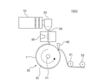
- FIG. 20 is a side view showing a reconstructed tobacco sheet manufacturing apparatus according to the 14th embodiment of the present invention.
- FIG. 21 is a block diagram showing hot air temperature control in the reconstructed tobacco sheet manufacturing apparatus according to the 14th embodiment of the present invention.
- the reconstructed tobacco sheet manufacturing apparatus 100I includes a water content sensor (state detection unit) 94 and a PLC (control unit) 200 in addition to the reconstructed tobacco sheet manufacturing apparatus 100 shown in FIG. Be prepared. Further, the reconstructed tobacco sheet manufacturing apparatus 100I has the hot air blower (auxiliary drying apparatus) 80 shown in the eleventh embodiment described above as an actuator. Since other configurations are the same as those of the first embodiment described above, the description thereof will be omitted.
- the water content sensor 94 is provided after the scraper 40.
- the water content sensor 94 detects the water content of the reconstructed tobacco sheet 1 peeled off by the scraper 40 in a non-contact manner using infrared rays, microwaves, or the like, and outputs it to the PLC 200 as a water content measurement value.
- the hot air blower 80 is arranged on the drying path of the drum dryer 30 so as to face the drum main body 32 of the drum dryer 30.
- the PLC 200 may be built in the reconstructed tobacco sheet manufacturing apparatus 100I, or may be provided at a distance.
- the difference between the water content setting value and the water content measurement value is zero based on the water content setting value which is the desired water content of the reconstructed tobacco sheet 1 and the water content measurement value from the water content sensor 94.
- a control command is output to the hot air blower 80 to control the temperature of the hot air sent from the hot air blower 80.
- the water content of the reconstructed tobacco sheet 1 dried by the drum dryer 30 and the hot air blower 80 changes.
- the water content of the reconstructed tobacco sheet 1 dried by the drum dryer 30 and the hot air blower 80 varies depending on the environment, the season, and the like. Therefore, by feedback-controlling the water content of the reconstructed tobacco sheet 1, the water content of the reconstructed tobacco sheet 1 dried by the drum dryer 30 and the hot air blower 80 can be kept within a certain range. As a result, the quality of the reconstructed tobacco sheet 1 can be stabilized. Further, since the hot air blower 80 has higher responsiveness and is easier to control than the drum dryer 30, the water content of the reconstructed tobacco sheet 1 can be controlled in detail. Further, since the water content of the reconstructed tobacco sheet 1 can be automatically controlled, it is possible to eliminate the need for constant monitoring by the operator.
- the reconstructed tobacco raw material discharged from the die is dried and transported, and the reconstructed tobacco raw material disposed facing the drum and discharged from the die is dried.
- the state detection unit detects the water content of the reconstituted tobacco raw material dried by the drum and the auxiliary drying device, and the control unit assists based on the detection result by the state detection unit.
- the drying device is controlled to change the moisture content of the reconstituted tobacco raw material dried by the drum and the auxiliary drying device. Therefore, the water content of the reconstructed tobacco sheet dried by the drum and the auxiliary drying device can be kept within a certain range.
- FIG. 22 is a side view showing a reconstructed tobacco sheet manufacturing apparatus according to the fifteenth embodiment of the present invention.
- the reconstructed tobacco sheet manufacturing apparatus 100J includes an addition mechanism 95 in addition to the reconstructed tobacco sheet manufacturing apparatus 100 shown in FIG. Since other configurations are the same as those of the first embodiment described above, the description thereof will be omitted.
- the addition mechanism 95 is provided in the vicinity of the discharge port 26, and a powdery or liquid fragrance is added to the reconstructed tobacco sheet 1 discharged from the die 20 by spraying.
- the installation position of the addition mechanism is not limited to the vicinity of the discharge port 26, and the addition mechanism may be provided on the drying path of the drum dryer 30.
- the reconstructed tobacco sheet 1 manufactured by the present invention has a smooth surface due to the pressure load on the die 20 and the shrinkage during drying on the drum dryer 30, so that the liquid permeability is low. Therefore, the fixability of the additive can be improved by adding the fragrance before or during the drying of the reconstructed tobacco sheet 1. Further, by providing the addition mechanism 95 in the reconstructed tobacco sheet manufacturing apparatus 100J, the step of adding the fragrance in the subsequent step becomes unnecessary.
- the fixing property of the additive can be improved by further providing an addition mechanism for adding the powdery or liquid fragrance on the downstream side of the die 20. ..
- FIG. 23 is a side view showing a reconstructed tobacco sheet manufacturing apparatus according to the 16th embodiment of the present invention.
- the reconstructed tobacco sheet manufacturing apparatus 100K includes a buffer mechanism 55 in addition to the reconstructed tobacco sheet manufacturing apparatus 100 shown in FIG. Since other configurations are the same as those of the first embodiment described above, the description thereof will be omitted.
- the buffer mechanism 55 is provided between the discharge port 26 and the drum dryer 30, and winds up the reconstructed tobacco sheet 1 discharged from the die 20 and temporarily holds it.
- the buffer mechanism 55 is suitable for a reconstituted tobacco raw material containing a small amount of water. Since the reconstructed tobacco sheet 1 before being dried by the drum dryer 30 has low strength, the structure of the buffer mechanism 55 is, for example, a fixed roller 56 and a movable roller 57 that can be moved according to the tension of the reconstructed tobacco sheet 1. Those having and are suitable.
- the buffer mechanism 55 moves the movable roller 57 so that the tension of the reconstructed tobacco sheet 1 becomes constant.
- the buffer mechanism 55 By providing the buffer mechanism 55, it corresponds to the case where the discharge speed of the reconstructed tobacco sheet 1 discharged from the die 20 and the rotation speed of the drum body 32 cannot be synchronized due to the fluctuation of the discharge amount from the die 20 or the like. can do. Specifically, by feeding out the reconstructed tobacco sheet 1 held in the buffer mechanism 55 or temporarily holding the reconstructed tobacco sheet 1 in the buffer mechanism 55, the discharge speed of the reconstructed tobacco sheet 1 can be determined. The rotation speed of the drum body 32 can be relatively synchronized. Further, even when the device upstream or downstream of the buffer mechanism 55 causes a chocolate stop, by using the buffer mechanism 55, it is possible to prevent the entire reconstructed tobacco sheet manufacturing device 100K from stopping. ..
- the reconstructed tobacco is further provided with the buffer mechanism 55 for temporarily holding the reconstructed tobacco sheet 1 discharged from the die 20 on the downstream side of the die 20. It is possible to deal with the case where the discharge speed of the sheet 1 and the rotation speed of the drum main body 32 cannot be synchronized.
Abstract
この再構成たばこシートの製造装置は、再構成たばこ原料を吐出するダイを備え、ダイは、ハウジングと、ハウジングに形成され、再構成たばこ原料が供給される供給口と、ハウジングの一側面に形成され、再構成たばこ原料を吐出する吐出口と、を有する。
Description
本発明は、再構成たばこシートの製造装置および製造方法に関する。
従来、再構成たばこシートの製造方法として、圧延法、キャスト(スラリー)法、抄造法が知られている。これらの製造方法は、再構成たばこ原料に含まれる水分量に応じて選択される。また、これらの製造方法のそれぞれは、互いに異なる再構成たばこシートの製造装置によって実現される。
圧延法は、特に50体積%以下の水分を含む再構成たばこ原料に適することが知られている。圧延法において、再構成たばこ原料の混練物は、回転ローラで圧延成形され、厚さが整えられた後、別途設けられた乾燥機で乾燥される。
キャスト(スラリー)法は、特に50体積%以上の水分を含む再構成たばこ原料に適することが知られている。キャスト(スラリー)法において、再構成たばこ原料の流動体は、回転ドラムまたはベルトコンベア上に連続的に展延され、ブレードと称される部材で所望の厚さに均された後、回転ドラムまたはベルトコンベアから剥離され、別途設けられた乾燥機で乾燥される(例えば、特許文献1参照)。
抄造法は、特に80体積%以上の水分を含む再構成たばこ原料に適することが知られている。抄造法において、再構成たばこ原料の流動体は、液体透過性のベルトコンベア上に連続的に展延され、圧搾ローラで水分が除去されかつ所望の厚さにされた後、別途設けられた乾燥機で乾燥される。
本発明の目的は、再構成たばこ原料に含まれる水分量によらず、簡素な製造工程で、均一な厚さの再構成たばこシートを得ることができる再構成たばこシートの製造装置および製造方法を提供することである。
本発明の第1形態によれば、再構成たばこシートの製造装置が提供される。この再構成たばこシートの製造装置は、再構成たばこ原料を吐出するダイを備え、ダイは、ハウジングと、ハウジングに形成され、再構成たばこ原料が供給される供給口と、ハウジングの一側面に形成され、再構成たばこ原料を吐出する吐出口と、を有する。これによれば、再構成たばこ原料に含まれる水分量によらず、簡素な製造工程で、均一な厚さの再構成たばこシートを得ることができる。
本発明の第2形態によれば、第1形態において、ダイを吐出口の長手方向に沿って複数配置した。これによれば、得られた再構成たばこシートを所望の幅に裁断する工程を省略することができる。
本発明の第3形態によれば、第1形態または第2形態において、ダイは、吐出口の幅方向長さを変更可能な可変幅機構を有する。これによれば、ダイを交換することなく、複数の厚さの再構成たばこシートを得ることができる。また、ダイの吐出口における再構成たばこ原料の流速が、吐出口の長手方向で一様となるように吐出口の開口幅を変更することで、しわの発生を抑制し、再構成たばこシートを平坦に成形することができる。
本発明の第4形態によれば、第1形態から第3形態のいずれかにおいて、ダイは、複数の原料がそれぞれ供給される複数の供給口を有し、複数の原料は、吐出口から積層して吐出される。これによれば、複数のシートを貼り合わせる工程を省略することができる。
本発明の第5形態によれば、第1形態から第4形態のいずれかにおいて、ダイは、吐出口の長手方向に沿って吐出口を複数の領域に分割する仕切り部を有する。これによれば、シートをストランド加工する工程を省略することができる。
本発明の第6形態によれば、再構成たばこシートの製造方法が提供される。この再構成たばこシートの製造方法は、再構成たばこ原料をダイの供給口に供給する工程と、ダイの吐出口から再構成たばこ原料をシート状に成形して吐出する工程と、を有する。これによれば、再構成たばこ原料に含まれる水分量によらず、簡素な製造工程で、均一な厚さの再構成たばこシートを得ることができる。
以下、本発明による再構成たばこシートの製造装置および製造方法について図面を用いて説明するが、各図において同一、または相当する部分については、同一符号を付して説明する。
第1実施形態:
図1は、本発明の第1実施形態に係る再構成たばこシートの製造装置を示す側面図である。図1において、再構成たばこシートの製造装置100は、押出機10、ダイ20、ドラムドライヤ(主ドラム)30、スクレッパ40およびローラ51、52を備える。ドラムドライヤ30は、軸31およびドラム本体32を有する。
図1は、本発明の第1実施形態に係る再構成たばこシートの製造装置を示す側面図である。図1において、再構成たばこシートの製造装置100は、押出機10、ダイ20、ドラムドライヤ(主ドラム)30、スクレッパ40およびローラ51、52を備える。ドラムドライヤ30は、軸31およびドラム本体32を有する。
押出機10は、図示しないタンク等から供給される再構成たばこ原料を、ダイ20に圧送する。ダイ20は、押出機10から供給される再構成たばこ原料を吐出し、これにより、再構成たばこ原料が再構成たばこシート1としてドラムドライヤ30のドラム本体32上に成形される。ドラムドライヤ30は、ドラム本体32上に成形された再構成たばこシート1を乾燥させるとともに搬送する。スクレッパ40は、ドラムドライヤ30で乾燥された再構成たばこシート1を、ドラム本体32から剥離する。ローラ51、52は、スクレッパ40で剥離された再構成たばこシート1の搬送を案内する。
ここで、再構成たばこ原料とは、多糖類(デンプンやデキストリン等)から選択される少なくとも1つの物質と、任意の液体の媒体として水またはアルコール(エタノールやプロピレングリコール等)または自ら選択される少なくとも1つの物質と、たばこ植物の細片または細粒とを含む混練物である。なお、再構成たばこ原料は、上記のものに限定されず、他の物質を含んでいてもよい。
図2は、本発明の第1実施形態に係る再構成たばこシートの製造装置の押出機を示す構成図である。また、図3は、図2に示した矢視III-IIIにおける断面図である。図2、3において、押出機10は、ハウジング11、ハウジング11の一端に形成された供給口12、ハウジング11の他端に形成された押出口13およびハウジング11内に回転可能に配設されたスクリュー14を有する。
タンク等から供給口12を介して押出機10に供給された再構成たばこ原料は、スクリュー14の回転によって混練されながら押出口13に送られ、押出口13からダイ20に圧送される。ここで、スクリュー14の回転速度に応じて、ダイ20から吐出される再構成たばこシート1の吐出速度が決定される。
図4は、本発明の第1実施形態に係る再構成たばこシートの製造装置のダイを示す断面図である。図5は、図4に示した矢視V-Vにおける断面図である。また、図6は、図4に示したダイを吐出口側から見た側面図である。図4~6において、ダイ20は、第1ブロック21および第2ブロック22からなるハウジング23と、第1ブロック21に形成され、押出機10の押出口13と連通する供給口24、第1ブロック21と第2ブロック22との間に形成され、再構成たばこ原料が貯留されるマニホールド25およびマニホールド25と連通する吐出口26を有する。
吐出口26は、ハウジング23の一側面にスリット状に形成されている。吐出口26の長手方向に直交する方向を、吐出口26の幅方向とする。また、吐出口26の長手方向長さを開口長さと称し、吐出口26の幅方向長さを開口幅と称する。なお、吐出口26は、孔状であってもよいし、溝状であってもよい。スリット状の吐出口26により、再構成たばこ原料は、再構成たばこ原料に含まれる水分量によらず、ダイ20からの吐出時に、吐出口26の開口幅に応じた均一な厚さに調整され、シート状に成形されて押し出される。
押出機10から供給口24を介してダイ20に供給された再構成たばこ原料は、マニホールド25を通って吐出口26に送られ、吐出口26から再構成たばこシート1としてドラム本体32上に吐出される。
図1に戻って、ドラムドライヤ30は、軸31と軸31を中心として回転するドラム本体32とを有する。ドラム本体32は、例えばドラム本体32内部に送り込まれる蒸気によって再構成たばこシート1を乾燥させる。なお、ドラム本体32は、ヒータ等によって加熱されてもよい。
スクレッパ40は、ドラム本体32の回転方向に直交するドラム本体32の幅方向の全長にわたって、ドラム本体32と対向して配置され、先端部がドラム本体32と当接ないし近接するように調整されている。なお、スクレッパ40は、ドラム本体32の回転方向の上流側で吐出された再構成たばこシート1が十分に乾燥されるように、ドラム本体32の回転方向の下流側の端部近傍に配置されている。
ダイ20の吐出口26からドラム本体32上に吐出された再構成たばこシート1は、内部に蒸気が送り込まれるドラム本体32によって乾燥され、乾燥された再構成たばこシート1は、スクレッパ40で剥離されて後段の工程に引き渡される。後段の工程とは、例えば再構成たばこシート1が所望の幅に裁断される工程や、裁断された再構成たばこシートがボビンに巻き取られる工程である。
すなわち、再構成たばこシート1は、再構成たばこ原料をダイ20の供給口24に供給する工程と、ダイ20の吐出口26から再構成たばこ原料をシート状に成形して吐出する工程と、を含む製造方法によって製造される。
以上のように、第1実施形態によれば、再構成たばこシートの製造装置は、再構成たばこ原料を吐出するダイと、ダイから吐出された再構成たばこ原料を乾燥させるとともに搬送する主ドラムと、を備え、ダイは、ハウジングと、ハウジングに形成され、再構成たばこ原料が供給される供給口と、ハウジングの一側面に形成され、再構成たばこ原料を吐出する吐出口と、を有する。そのため、再構成たばこ原料に含まれる水分量によらず、簡素な製造工程で、均一な厚さの再構成たばこシートを得ることができる。
第2実施形態:
図7は、本発明の第2実施形態に係る再構成たばこシートの製造装置を示す平面図である。図7において、再構成たばこシートの製造装置100Aは、図1に示した押出機10およびダイ20に代えて、X個の押出機10A~10XおよびX個のダイ20A~20Xを備える。なお、Xは、2以上であればよい。また、1個の押出機10に、X個のダイ20A~20Xが接続されてもよい。その他の構成は、上述した第1実施形態と同様なので、説明を省略する。
図7は、本発明の第2実施形態に係る再構成たばこシートの製造装置を示す平面図である。図7において、再構成たばこシートの製造装置100Aは、図1に示した押出機10およびダイ20に代えて、X個の押出機10A~10XおよびX個のダイ20A~20Xを備える。なお、Xは、2以上であればよい。また、1個の押出機10に、X個のダイ20A~20Xが接続されてもよい。その他の構成は、上述した第1実施形態と同様なので、説明を省略する。
押出機10A~10Xは、それぞれダイ20A~20Xと接続される。また、ダイ20A~20Xは、吐出口26の長手方向に沿って配置されている。押出機10A~10Xは、図示しないタンク等から供給される再構成たばこ原料を、それぞれダイ20A~20Xに圧送する。ダイ20A~20Xは、押出機10A~10Xから供給される再構成たばこ原料を、それぞれドラム本体32上に吐出する。
ここで、ダイ20A~20Xの吐出口26の開口長さを、上述した後段の工程において再構成たばこシート1が巻き取られるボビンの幅に合わせることにより、上述した後段の工程における、再構成たばこシート1を所望の幅に裁断する工程が不要になる。また、ダイ20A~20Xのそれぞれの開口幅を互いに異なるものにすることで、一台のドラムドライヤ30で複数の厚さの再構成たばこシート1を製造することができる。
また、押出機10A~10Xのそれぞれに供給される再構成たばこ原料の組成を互いに異なるものにすることで、一台のドラムドライヤ30で複数種類の再構成たばこシート1を製造することができる。さらに、押出機10A~10Xおよびダイ20A~20Xの組を選択的に駆動させることにより、再構成たばこシートの製造装置100Aの製造能力を容易に調整することができる。
以上のように、第2実施形態によれば、ダイを吐出口の長手方向に沿って複数配置している。そのため、得られた再構成たばこシートを所望の幅に裁断する工程を省略することができる。
第3実施形態:
上記第1実施形態では、ダイ20の吐出口26の開口幅を一定としたが、本発明の第3実施形態に係る再構成たばこシートの製造装置において、ダイ20は、吐出口26の開口幅を変更可能な可変幅機構(図示せず)を有する。その他の構成は、上述した第1実施形態と同様なので、説明を省略する。
上記第1実施形態では、ダイ20の吐出口26の開口幅を一定としたが、本発明の第3実施形態に係る再構成たばこシートの製造装置において、ダイ20は、吐出口26の開口幅を変更可能な可変幅機構(図示せず)を有する。その他の構成は、上述した第1実施形態と同様なので、説明を省略する。
可変幅機構は、例えばねじである。可変幅機構は、ねじの締め付け量に応じて、図6に示した第1ブロック21と第2ブロック22との間隙を調整することで、吐出口26の開口幅を変更する。なお、ねじが複数設けられ、吐出口26の長手方向の端部と中央部とで、吐出口26の開口幅を異ならしめるように構成されてもよい。吐出口26の開口幅と比して吐出口26の開口長さが大きいと、吐出口26の長手方向において吐出状態が異なることが発生する。前述のように吐出口26の長手方向に複数の可変幅機構を有することは、再構成たばこシート1の幅方向での状態を整えるために好ましい。また、可変幅機構は、ねじを駆動させるモータ等のアクチュエータを有していてもよい。可変幅機構を用いることにより、再構成たばこシート1の厚さを容易に変更することができる。
以上のように、第3実施形態によれば、ダイは、吐出口の幅方向長さを変更可能な可変幅機構を有する。そのため、ダイを交換することなく、複数の厚さの再構成たばこシートを得ることができる。また、ダイの吐出口における再構成たばこ原料の流速が、吐出口の長手方向で一様となるように吐出口の開口幅を変更することで、しわの発生を抑制し、再構成たばこシートを平坦に成形することができる。
第4実施形態:
図8は、本発明の第4実施形態に係る再構成たばこシートの製造装置を示す側面図である。図8において、再構成たばこシートの製造装置100Bは、図1に示した押出機10およびダイ20に代えて、3個の押出機61~63およびダイ70を備える。なお、押出機の数は、3個に限定されず、2個以上であればよい。その他の構成は、上述した第1実施形態と同様なので、説明を省略する。
図8は、本発明の第4実施形態に係る再構成たばこシートの製造装置を示す側面図である。図8において、再構成たばこシートの製造装置100Bは、図1に示した押出機10およびダイ20に代えて、3個の押出機61~63およびダイ70を備える。なお、押出機の数は、3個に限定されず、2個以上であればよい。その他の構成は、上述した第1実施形態と同様なので、説明を省略する。
押出機61~63は、ダイ70と接続される。押出機61~63には、それぞれ図示しないタンク等から原料が供給される。押出機61~63に供給される原料の少なくとも1つは、再構成たばこ原料を含んでいる。また、押出機61~63に供給される原料は、互いに異なる原料であっても、同一の原料を含んでいてもよい。押出機61~63は、図示しないスクリュー等を用いて、供給された原料をダイ70に圧送する。
ダイ70は、押出機61~63から複数の原料がそれぞれ供給される複数の供給口71~73と、ダイ70の一側面にスリット状に形成された吐出口74とを有する。ダイ70は、押出機61~63から供給口71~73を介して供給された原料を、それぞれ図示しないマニホールドで広げた後、吐出口74の近傍で合流させて、積層された再構成たばこシート1をドラム本体32上に吐出する。なお、ダイ70は、マニホールドにおいて複数の原料を合流させてもよい。
ここで、ダイ70の吐出口74から複数の原料が積層されて吐出されることにより、異なる特性を持ったシートを貼り合わせることなく多層化することができる。そのため、シートの貼り合わせ工程を省略して、簡素な構成で多層化された再構成たばこシート1を得ることができる。また、ドラムドライヤ30で再構成たばこシート1を乾燥させる前にシートを多層化することにより、各層の接着を強化することができる。さらに、多層化されたシートの中に、べたつきを抑制したシートを入れ込むことで、打ち粉や剥離紙等の対応をとることなく、再構成たばこシート1のボビンへの巻き取りおよびボビンからの繰り出しを容易に行うことができる。
以上のように、第4実施形態によれば、ダイは、複数の原料がそれぞれ供給される複数の供給口を有し、複数の原料は、吐出口から積層して吐出される。そのため、複数のシートを貼り合わせる工程を省略することができる。
第5実施形態:
図9は、本発明の第5実施形態に係る再構成たばこシートの製造装置のダイを吐出口側から見た側面図である。図9において、ダイ20は、吐出口26の長手方向に沿って吐出口26を複数の領域に分割する仕切り部27をさらに有する。すなわち、図9において、図6に示したスリット状の吐出口26は、間欠状に開口したものとなる。その他の構成は、上述した第1実施形態と同様なので、説明を省略する。
図9は、本発明の第5実施形態に係る再構成たばこシートの製造装置のダイを吐出口側から見た側面図である。図9において、ダイ20は、吐出口26の長手方向に沿って吐出口26を複数の領域に分割する仕切り部27をさらに有する。すなわち、図9において、図6に示したスリット状の吐出口26は、間欠状に開口したものとなる。その他の構成は、上述した第1実施形態と同様なので、説明を省略する。
押出機10から供給口24を介してダイ20に供給された再構成たばこ原料は、マニホールド25を通って吐出口26に送られ、吐出口26から再構成たばこシート1としてドラム本体32上に吐出される。このとき、吐出口26が間欠状に開口していることから、吐出された再構成たばこシート1は、すでにストリップ状に成形されている。そのため、ドラムドライヤ30で乾燥された再構成たばこシート1を、乾燥終了後そのままストランドとして回収することができる。
以上のように、第5実施形態によれば、ダイは、吐出口の長手方向に沿って吐出口を複数の領域に分割する仕切り部を有する。そのため、シートをストランド加工する工程を省略することができる。また、本発明では、乾燥前であっても、吐出された再構成たばこシートの形状が安定していることから、仕切り部27を有するダイ20を用いることは、有効である。
第6実施形態:
図10は、本発明の第6実施形態に係る再構成たばこシートの製造装置のダイを吐出口側から見た側面図である。図10において、ダイ20は、吐出口26の長手方向に沿って吐出口26の幅方向を向く少なくとも1つの隆起部28をさらに有する。ここで、隆起部28の断面形状は、三角形、矩形、正弦波形、T字形等であってよい。すなわち、図10において、図6に示したスリット状の吐出口26は、隆起部28の頂点または頂点を含む辺と隆起部28の底辺とで、2つの幅を有する開口となる。その他の構成は、上述した第1実施形態と同様なので、説明を省略する。
図10は、本発明の第6実施形態に係る再構成たばこシートの製造装置のダイを吐出口側から見た側面図である。図10において、ダイ20は、吐出口26の長手方向に沿って吐出口26の幅方向を向く少なくとも1つの隆起部28をさらに有する。ここで、隆起部28の断面形状は、三角形、矩形、正弦波形、T字形等であってよい。すなわち、図10において、図6に示したスリット状の吐出口26は、隆起部28の頂点または頂点を含む辺と隆起部28の底辺とで、2つの幅を有する開口となる。その他の構成は、上述した第1実施形態と同様なので、説明を省略する。
押出機10から供給口24を介してダイ20に供給された再構成たばこ原料は、マニホールド25を通って吐出口26に送られ、吐出口26から再構成たばこシート1としてドラム本体32上に吐出される。このとき、吐出口26に隆起部28が設けられていることから、吐出された再構成たばこシート1には、すでに隆起部28に対応する断面形状の条が形成されている。そのため、ドラムドライヤ30で乾燥された再構成たばこシート1を、乾燥終了後そのまま条が形成された再構成たばこシート1として回収することができる。
以上のように、第6実施形態によれば、ダイは、吐出口の長手方向に沿って吐出口の幅方向を向く少なくとも1つの隆起部を有する。そのため、従来の再構成たばこシートで行われていたような、対となるローラの間に再構成たばこシートを通し、ジグザグや波形の形状を押圧加工する工程を省略しながらも、再構成たばこシートの重量当たりの表面積を増す表面加工(例えば、エンボス加工)を行うことができる。また、本発明では、乾燥前であっても、吐出された再構成たばこシートの形状が安定していることから、隆起部28を有するダイ20を用いることは、有効である。
なお、図11に示されるように、隆起部28がT字形である場合には、再構成たばこシート1に形成された条が、再構成たばこシート1内で広がることになる。このような表面形状は、ローラによる再構成たばこシート1の押圧加工によって得られるものではなく、第6実施形態で示したダイ20を用いることによってのみ得られるものである。
第7実施形態:
図12は、本発明の第7実施形態に係る再構成たばこシートの製造装置を示す側面図である。図12において、再構成たばこシートの製造装置100Cは、図1に示した再構成たばこシートの製造装置100に加えて、ドラムドライヤ(副ドラム)35およびスクレッパ45を備える。その他の構成は、上述した第1実施形態と同様なので、説明を省略する。
図12は、本発明の第7実施形態に係る再構成たばこシートの製造装置を示す側面図である。図12において、再構成たばこシートの製造装置100Cは、図1に示した再構成たばこシートの製造装置100に加えて、ドラムドライヤ(副ドラム)35およびスクレッパ45を備える。その他の構成は、上述した第1実施形態と同様なので、説明を省略する。
ドラムドライヤ35は、ドラムドライヤ30の後段に配置され、ドラムドライヤ30と組み合わせて用いられる。ドラムドライヤ35は、軸36と軸36を中心として回転するドラム本体37とを有する。ドラム本体37は、例えばドラム本体37内部に送り込まれる蒸気によって加熱される。なお、ドラム本体37は、ヒータ等によって加熱されてもよい。また、ドラムドライヤ30およびドラムドライヤ35は、それぞれ独立して温度調節することができるよう構成されている。
ドラムドライヤ35は、ドラムドライヤ30で乾燥され、スクレッパ40で剥離された再構成たばこシート1を受け取って、再構成たばこシート1をさらに乾燥させるとともに搬送する。スクレッパ45は、ドラムドライヤ35で乾燥された再構成たばこシート1を、ドラム本体37から剥離する。
ここで、ドラムドライヤ30およびドラムドライヤ35を用いることにより、再構成たばこシート1の乾燥距離を延ばして、再構成たばこシートの製造装置100Cの乾燥能力を向上させることができる。そのため、水分量が多い再構成たばこ原料にも対応することができる。
また、同一の乾燥距離について、ドラム径の互いに等しい2つのドラムドライヤを用いる場合と、1つのドラムドライヤを用いる場合とを比較すると、2つのドラムドライヤを用いる場合には、それぞれのドラム径を1つのドラムドライヤのドラム径の半分にすることができる。すなわち、2つのドラムドライヤの総体積を、1つのドラムドライヤの半分にすることができる。そのため、2つのドラムドライヤを用いる場合には、必要な熱エネルギーを、1つのドラムドライヤを用いる場合の半分にすることができる。
以上のように、第7実施形態によれば、主ドラムと組み合わせて用いられる副ドラムをさらに備え、副ドラムは、主ドラムの後段に配置され、主ドラムによって搬送された再構成たばこ原料を、主ドラムから受け取ってさらに搬送する。そのため、再構成たばこ原料の搬送距離を延ばしながら、主ドラムで乾燥および搬送される再構成たばこ原料に対してさらなる処理を施すことができる。なお、第7実施形態では、副ドラムをドラムドライヤとしたが、これに限定されず、副ドラムは、ドラムドライヤ30で乾燥された再構成たばこシート1を冷却する冷却ドラムであってもよい。
第8実施形態:
図13は、本発明の第8実施形態に係る再構成たばこシートの製造装置を示す側面図である。図13において、再構成たばこシートの製造装置100Dは、図1に示した再構成たばこシートの製造装置100に加えて、ドラムドライヤ(副ドラム)35を備える。その他の構成は、上述した第1実施形態と同様なので、説明を省略する。
図13は、本発明の第8実施形態に係る再構成たばこシートの製造装置を示す側面図である。図13において、再構成たばこシートの製造装置100Dは、図1に示した再構成たばこシートの製造装置100に加えて、ドラムドライヤ(副ドラム)35を備える。その他の構成は、上述した第1実施形態と同様なので、説明を省略する。
ドラムドライヤ35は、ドラムドライヤ30と対向して配置され、ドラムドライヤ30と組み合わせて用いられる。ドラムドライヤ35は、軸36と軸36を中心として回転するドラム本体37とを有する。軸36は、図示しない駆動機構によって、ドラムドライヤ30とドラムドライヤ35との間隙を任意に調整することができるよう構成されている。
ドラム本体37は、例えばドラム本体37内部に送り込まれる蒸気によって加熱される。なお、ドラム本体37は、ヒータ等によって加熱されてもよい。また、ドラムドライヤ30およびドラムドライヤ35は、それぞれ独立して温度調節することができるよう構成されている。
ドラムドライヤ35は、ドラム本体32上に成形された再構成たばこシート1を、ドラムドライヤ30と協働して乾燥させるとともに搬送する。ドラムドライヤ30およびドラムドライヤ35によって搬送される再構成たばこシート1は、ドラムドライヤ30とドラムドライヤ35との間隙を通過する際に圧縮される。
ここで、ドラムドライヤ30とドラムドライヤ35とで再構成たばこシート1を圧縮することにより、ドラムドライヤ30およびドラムドライヤ35による圧密効果で、再構成たばこシート1の密度を、ダイ20からの吐出時よりも高めることができる。また、ドラムドライヤ30とドラムドライヤ35との間隙を調整することで、ドラムドライヤ30とドラムドライヤ35との間隙を通過した再構成たばこシート1の厚さを制御することができる。
また、ドラムドライヤ30とドラムドライヤ35との間隙に再構成たばこシート1を通すことにより、ドラムドライヤ30およびドラムドライヤ35による圧密効果で、ダイ20からの吐出時に、吐出速度の分布によって再構成たばこシート1に発生するしわ等を解消することができる。また、ドラム本体37の表面にエンボス加工を行うことにより、再構成たばこシート1がドラムドライヤ30とドラムドライヤ35との間隙を通過する際に、再構成たばこシート1の表面にエンボス処理を施すことができ、比表面積を拡大することができる。なお、ドラム本体37の表面に行われる加工は、エンボス加工に限定されず、再構成たばこシート1を裁断するためのスリット加工等であってもよい。
以上のように、第8実施形態によれば、主ドラムと組み合わせて用いられる副ドラムをさらに備え、副ドラムは、主ドラムと対向して配置され、主ドラムと協働してダイから吐出された再構成たばこ原料を搬送する。そのため、主ドラムと協働して、主ドラムで乾燥および搬送される再構成たばこ原料に対してさらなる処理を施すことができる。
第9実施形態:
図14は、本発明の第9実施形態に係る再構成たばこシートの製造装置を示す側面図である。図14において、再構成たばこシートの製造装置100Eは、図13に示した再構成たばこシートの製造装置100Dに加えて、ドラムドライヤ35に設けられた押出機10およびダイ20を備える。その他の構成は、上述した第8実施形態と同様なので、説明を省略する。
図14は、本発明の第9実施形態に係る再構成たばこシートの製造装置を示す側面図である。図14において、再構成たばこシートの製造装置100Eは、図13に示した再構成たばこシートの製造装置100Dに加えて、ドラムドライヤ35に設けられた押出機10およびダイ20を備える。その他の構成は、上述した第8実施形態と同様なので、説明を省略する。
ドラムドライヤ35に設けられた押出機10には、図示しないタンク等から供給される原料が供給される。押出機10に供給される原料は、再構成たばこ原料を含んでいてもよいし、含んでいなくてもよい。押出機10は、図示しないスクリュー等を用いて、供給された原料をダイ20に圧送する。ドラムドライヤ35に設けられたダイ20は、押出機10から供給される原料を、シート状に成形してドラム本体37上に吐出する。ドラムドライヤ30に設けられたダイ20およびドラムドライヤ35に設けられたダイ20のそれぞれから吐出されたシートは、ドラムドライヤ30とドラムドライヤ35との間隙を通過する際に多層化される。
ここで、ドラムドライヤ30とドラムドライヤ35との間隙に、ドラムドライヤ30およびドラムドライヤ35のそれぞれに設けられたダイ20から吐出されたシートを通すことにより、異なる特性を持ったシートを貼り合わせることなく多層化することができる。そのため、シートの貼り合わせ工程を省略して、簡素な構成で多層化された再構成たばこシート1を得ることができる。また、ドラムドライヤ30およびドラムドライヤ35で再構成たばこシート1を乾燥させる前にシートを多層化することにより、各層の接着を強化することができる。さらに、ドラムドライヤ30とドラムドライヤ35との間隙を調整することで、ドラムドライヤ30とドラムドライヤ35との間隙を通過した再構成たばこシート1の厚さを制御することができる。
以上のように、第9実施形態によれば、主ドラムと組み合わせて用いられる副ドラムと、主ドラムに設けられたダイと同一の構成を有し、副ドラムに対して吐出材料を吐出するダイをさらに備える。そのため、複数のシートを貼り合わせる工程を省略することができる。
第10実施形態:
本発明の第10実施形態に係る再構成たばこシートの製造装置では、上記第1実施形態等で示したドラムドライヤ30のドラム本体32やドラムドライヤ35のドラム本体37の表面に対して、特性の改善を狙って表面改質処理が施されている。
本発明の第10実施形態に係る再構成たばこシートの製造装置では、上記第1実施形態等で示したドラムドライヤ30のドラム本体32やドラムドライヤ35のドラム本体37の表面に対して、特性の改善を狙って表面改質処理が施されている。
ここで、特性の改善とは、耐摩耗性、耐腐食性、剥離/離型性、熱伝導性の改善であり、表面改質処理は、メッキ等の化学的処理やブラスト等の物理的処理を含む。具体的な特性と表面改質処理との例を、表1~6に示す。これにより、ドラムドライヤ30のドラム本体32やドラムドライヤ35のドラム本体37の表面の特性が改善され、装置の使用性や耐久性を向上させることができる。


当業者は、表1~6に記載の表面改質処理から、目的に適切な表面加工を選択し適用できる。なお、表1~6において、◎は、押出材料または装置の条件によらず、表面処理として適用できることを示している。また、表1~6において、○は、押出材料または装置の条件いずれかが整えば、表面処理として適用できることを示している。また、表1~6において、△は、押出材料および装置の条件がどちらも整えば、表面処理として適用できることを示している。また、表1~6において、※は、押出材料の条件(温度や粘度)と装置の条件(ドラム表面の温度やドラム表面の運動速度)とが整えば、表面処理として適用できることを示している。また、表3において、絶縁とは、絶縁により表面で電解腐食が起こりにくいことを示している。
以上のように、第10実施形態によれば、主ドラムは、表面改質処理が施されている。そのため、主ドラムの表面の特性を改善することができる。なお、主ドラムに限定されず、副ドラムに対して表面改質処理が施されていてもよい。
第11実施形態:
図15は、本発明の第11実施形態に係る再構成たばこシートの製造装置を示す側面図である。図15において、再構成たばこシートの製造装置100Fは、図1に示した再構成たばこシートの製造装置100に加えて、熱風ブロア(補助乾燥装置)80を備える。その他の構成は、上述した第1実施形態と同様なので、説明を省略する。
図15は、本発明の第11実施形態に係る再構成たばこシートの製造装置を示す側面図である。図15において、再構成たばこシートの製造装置100Fは、図1に示した再構成たばこシートの製造装置100に加えて、熱風ブロア(補助乾燥装置)80を備える。その他の構成は、上述した第1実施形態と同様なので、説明を省略する。
熱風ブロア80は、ドラムドライヤ30の乾燥経路上に、ドラムドライヤ30のドラム本体32と対向して配置されている。熱風ブロア80は、熱風を送って、ダイ20の吐出口26からドラム本体32上に吐出された再構成たばこシート1を、再構成たばこシート1の表面側から乾燥させる。ここで、再構成たばこシート1の表面とは、再構成たばこシート1のドラム本体32と接触していない面である。また、熱風ブロア80は、風量、出力、熱風温度といった固有のパラメタにより乾燥能力を調整することができるよう構成されている。また、熱風温度は、常温以上の温度に設定することができる。
ここで、熱風ブロア80を用いることにより、再構成たばこシートの製造装置100Fの乾燥能力を向上させることができる。そのため、簡素な構成で、水分量が多い再構成たばこ原料にも対応することができる。また、熱風ブロア80を用いることにより、再構成たばこシート1の両面を同時に乾燥させることができる。
以上のように、第11実施形態によれば、主ドラムと対向して配置され、ダイから吐出された再構成たばこ原料を乾燥させる補助乾燥装置をさらに備える。そのため、再構成たばこシートの製造装置の乾燥能力を向上させることができる。なお、第11実施形態では、補助乾燥装置を熱風ブロアとしたが、これに限定されず、補助乾燥装置は、IRヒータであってもよい。また、補助乾燥装置に代えて、再構成たばこシート1に冷風を送る冷却装置を備えていてもよい。
第12実施形態:
図16は、本発明の第12実施形態に係る再構成たばこシートの製造装置を示す側面図である。図17は、本発明の第12実施形態に係る再構成たばこシートの製造装置における開口幅制御を示すブロック図である。図16、17において、再構成たばこシートの製造装置100Gは、図1に示した再構成たばこシートの製造装置100に加えて、厚さ検出センサ(状態検出部)91およびPLC(制御部)200を備える。また、再構成たばこシートの製造装置100Gのダイ20は、上述した第3実施形態で示した、モータをアクチュエータとして、吐出口26の開口幅を変更可能な可変幅機構92を有する。その他の構成は、上述した第1実施形態と同様なので、説明を省略する。
図16は、本発明の第12実施形態に係る再構成たばこシートの製造装置を示す側面図である。図17は、本発明の第12実施形態に係る再構成たばこシートの製造装置における開口幅制御を示すブロック図である。図16、17において、再構成たばこシートの製造装置100Gは、図1に示した再構成たばこシートの製造装置100に加えて、厚さ検出センサ(状態検出部)91およびPLC(制御部)200を備える。また、再構成たばこシートの製造装置100Gのダイ20は、上述した第3実施形態で示した、モータをアクチュエータとして、吐出口26の開口幅を変更可能な可変幅機構92を有する。その他の構成は、上述した第1実施形態と同様なので、説明を省略する。
厚さ検出センサ91は、吐出口26の近傍に設けられている。厚さ検出センサ91は、X線やレーザ、超音波等を用いて、ダイ20から吐出された再構成たばこシート1の厚さを非接触で検出し、厚さ測定値としてPLC(programmable logic controller)200に出力する。
PLC200は、再構成たばこシートの製造装置100Gに内蔵されてもよいし、離隔して設けられてもよい。PLC200は、再構成たばこシート1の所望の厚さである厚さ設定値と、厚さ検出センサ91からの厚さ測定値とに基づいて、厚さ設定値と厚さ測定値との差がゼロになるように、可変幅機構92に制御指令を出力し、モータを制御する。これにより、吐出口26の開口幅が変更され、ダイ20から吐出される再構成たばこシート1の厚さが変化する。
再構成たばこシート1がダイ20から吐出される際、圧力開放によるシートの膨張が生じ、再構成たばこシート1の厚さが吐出口26の開口幅と一致しないことがある。そこで、圧力開放という制御できない要素に対して、吐出口26の開口幅をフィードバック制御することにより、再構成たばこシート1の厚さを所望の厚さに合わせることができる。
以上のように、第12実施形態によれば、ダイは、アクチュエータとして、吐出口の幅方向長さを変更可能な可変幅機構を有し、状態検出部は、ダイから吐出された再構成たばこ原料の厚さを検出し、制御部は、状態検出部による検出結果に基づいて、可変幅機構を制御し、吐出口の幅方向長さを変化させる。そのため、再構成たばこシートの厚さを所望の厚さに合わせることができる。
第13実施形態:
図18は、本発明の第13実施形態に係る再構成たばこシートの製造装置を示す側面図である。図19は、本発明の第13実施形態に係る再構成たばこシートの製造装置における吐出速度制御を示すブロック図である。図18、19において、再構成たばこシートの製造装置100Hは、図1に示した再構成たばこシートの製造装置100に加えて、流量センサ(状態検出部)93およびPLC(制御部)200を備える。また、再構成たばこシートの製造装置100Hにおいて、押出機10のハウジング11内に回転可能に配設されたスクリュー14が、アクチュエータとしての機能を有する。その他の構成は、上述した第1実施形態と同様なので、説明を省略する。
図18は、本発明の第13実施形態に係る再構成たばこシートの製造装置を示す側面図である。図19は、本発明の第13実施形態に係る再構成たばこシートの製造装置における吐出速度制御を示すブロック図である。図18、19において、再構成たばこシートの製造装置100Hは、図1に示した再構成たばこシートの製造装置100に加えて、流量センサ(状態検出部)93およびPLC(制御部)200を備える。また、再構成たばこシートの製造装置100Hにおいて、押出機10のハウジング11内に回転可能に配設されたスクリュー14が、アクチュエータとしての機能を有する。その他の構成は、上述した第1実施形態と同様なので、説明を省略する。
流量センサ93は、吐出口26の近傍に設けられている。流量センサ93は、レーザ等を用いて、ダイ20から吐出された再構成たばこシート1の流量を非接触で検出し、流量測定値としてPLC200に出力する。ここで、流量測定値は、ダイ20から吐出される再構成たばこシート1の吐出速度を推定するための値として用いられる。
PLC200は、再構成たばこシートの製造装置100Hに内蔵されてもよいし、離隔して設けられてもよい。PLC200は、再構成たばこシート1の所望の流量である流量設定値と、流量センサ93からの流量測定値とに基づいて、流量設定値と流量測定値との差がゼロになるように、スクリュー14に制御指令を出力し、スクリュー14の回転を制御する。これにより、ダイ20から吐出される再構成たばこシート1の吐出速度が変化する。
ダイ20から吐出される再構成たばこシート1の吐出速度は、スクリュー14のうねりによってある程度のばらつきを生じる。そこで、再構成たばこシート1の吐出速度をフィードバック制御することにより、ダイ20から吐出される再構成たばこシート1の吐出速度を一定の範囲に保つことができる。また、再構成たばこシート1の吐出速度を一定に保つことで、ドラムドライヤ30上で再構成たばこシート1がダブついたり、テンションの増大により再構成たばこシート1が引きちぎれたりすることを抑制することができる。さらに、再構成たばこシート1の吐出速度を一定に保つことで、圧力開放に伴うシートの厚さのばらつきを抑制し、再構成たばこシート1の品質を安定させることができる。
以上のように、第13実施形態によれば、ダイに再構成たばこ原料を圧送する押出機をさらに備え、押出機は、アクチュエータとして、ハウジング内に回転可能に配設されたスクリューを有し、状態検出部は、ダイから吐出された再構成たばこ原料の流量および吐出圧の少なくとも一方を検出し、制御部は、状態検出部による検出結果に基づいて、スクリューの回転を制御し、ダイから吐出される再構成たばこ原料の吐出速度を変化させる。そのため、ダイから吐出される再構成たばこシートの吐出速度を一定に保つことができる。
なお、第13実施形態において、流量センサ93に代えて、または流量センサ93に加えて、吐出口26の近傍またはダイ20の内部に、ダイ20から吐出される再構成たばこシート1の吐出圧を検出する吐出圧センサを設けてもよい。この場合、吐出圧センサで検出された吐出圧を、ダイ20から吐出される再構成たばこシート1の吐出速度を推定するための値として用いることができる。
第14実施形態:
図20は、本発明の第14実施形態に係る再構成たばこシートの製造装置を示す側面図である。図21は、本発明の第14実施形態に係る再構成たばこシートの製造装置における熱風温度制御を示すブロック図である。図20、21において、再構成たばこシートの製造装置100Iは、図1に示した再構成たばこシートの製造装置100に加えて、水分量センサ(状態検出部)94およびPLC(制御部)200を備える。また、再構成たばこシートの製造装置100Iは、上述した第11実施形態で示した熱風ブロア(補助乾燥装置)80を、アクチュエータとして有する。その他の構成は、上述した第1実施形態と同様なので、説明を省略する。
図20は、本発明の第14実施形態に係る再構成たばこシートの製造装置を示す側面図である。図21は、本発明の第14実施形態に係る再構成たばこシートの製造装置における熱風温度制御を示すブロック図である。図20、21において、再構成たばこシートの製造装置100Iは、図1に示した再構成たばこシートの製造装置100に加えて、水分量センサ(状態検出部)94およびPLC(制御部)200を備える。また、再構成たばこシートの製造装置100Iは、上述した第11実施形態で示した熱風ブロア(補助乾燥装置)80を、アクチュエータとして有する。その他の構成は、上述した第1実施形態と同様なので、説明を省略する。
水分量センサ94は、スクレッパ40の後段に設けられている。水分量センサ94は、赤外線やマイクロ波等を用いて、スクレッパ40で剥離された再構成たばこシート1の水分量を非接触で検出し、水分量測定値としてPLC200に出力する。熱風ブロア80は、ドラムドライヤ30の乾燥経路上に、ドラムドライヤ30のドラム本体32と対向して配置されている。
PLC200は、再構成たばこシートの製造装置100Iに内蔵されてもよいし、離隔して設けられてもよい。PLC200は、再構成たばこシート1の所望の水分量である水分量設定値と、水分量センサ94からの水分量測定値とに基づいて、水分量設定値と水分量測定値との差がゼロになるように、熱風ブロア80に制御指令を出力し、熱風ブロア80から送られる熱風の温度を制御する。これにより、ドラムドライヤ30および熱風ブロア80で乾燥される再構成たばこシート1の水分量が変化する。
ドラムドライヤ30および熱風ブロア80で乾燥される再構成たばこシート1の水分量は、環境や季節等によって変動する。そこで、再構成たばこシート1の水分量をフィードバック制御することにより、ドラムドライヤ30および熱風ブロア80で乾燥される再構成たばこシート1の水分量を一定の範囲に保つことができる。この結果、再構成たばこシート1の品質を安定させることができる。また、ドラムドライヤ30と比較して、熱風ブロア80は応答性が高く制御も容易であることから、再構成たばこシート1の水分量を詳細に制御することができる。さらに、再構成たばこシート1の水分量を自動で制御できるので、オペレータの常時監視を不要とすることができる。
以上のように、第14実施形態によれば、ダイから吐出された再構成たばこ原料を乾燥させるとともに搬送するドラムと、ドラムと対向して配置され、ダイから吐出された再構成たばこ原料を乾燥させる補助乾燥装置と、をさらに備え、状態検出部は、ドラムおよび補助乾燥装置によって乾燥された再構成たばこ原料の水分量を検出し、制御部は、状態検出部による検出結果に基づいて、補助乾燥装置を制御し、ドラムおよび補助乾燥装置によって乾燥される再構成たばこ原料の水分量を変化させる。そのため、ドラムおよび補助乾燥装置によって乾燥される再構成たばこシートの水分量を一定の範囲に保つことができる。
なお、第12実施形態に係る再構成たばこシートの製造装置100Gと、第13実施形態に係る再構成たばこシートの製造装置100Hと、第14実施形態に係る再構成たばこシートの製造装置100Iとを任意に組み合わせてもよい。
第15実施形態:
図22は、本発明の第15実施形態に係る再構成たばこシートの製造装置を示す側面図である。図22において、再構成たばこシートの製造装置100Jは、図1に示した再構成たばこシートの製造装置100に加えて、添加機構95を備える。その他の構成は、上述した第1実施形態と同様なので、説明を省略する。
図22は、本発明の第15実施形態に係る再構成たばこシートの製造装置を示す側面図である。図22において、再構成たばこシートの製造装置100Jは、図1に示した再構成たばこシートの製造装置100に加えて、添加機構95を備える。その他の構成は、上述した第1実施形態と同様なので、説明を省略する。
添加機構95は、吐出口26の近傍に設けられ、ダイ20から吐出された再構成たばこシート1に粉末状または液体状の香料を噴射により添加する。なお、添加機構の設置位置は、吐出口26の近傍に限定されず、添加機構は、ドラムドライヤ30の乾燥経路上に設けられてもよい。
本発明によって製造される再構成たばこシート1は、ダイ20での圧力負荷と、ドラムドライヤ30での乾燥時の収縮とにより、表面が平滑になっているため、液体浸透性が低い。そこで、再構成たばこシート1の乾燥前、または乾燥中に香料を添加することにより、添加物の定着性を向上させることができる。また、再構成たばこシートの製造装置100Jに添加機構95を設けることにより、後段の工程で香料を添加する工程が不要になる。
以上のように、第15実施形態によれば、ダイ20の下流側に、粉末状または液体状の香料を添加する添加機構をさらに備えたことにより、添加物の定着性を向上させることができる。
第16実施形態:
図23は、本発明の第16実施形態に係る再構成たばこシートの製造装置を示す側面図である。図23において、再構成たばこシートの製造装置100Kは、図1に示した再構成たばこシートの製造装置100に加えて、バッファ機構55を備える。その他の構成は、上述した第1実施形態と同様なので、説明を省略する。
図23は、本発明の第16実施形態に係る再構成たばこシートの製造装置を示す側面図である。図23において、再構成たばこシートの製造装置100Kは、図1に示した再構成たばこシートの製造装置100に加えて、バッファ機構55を備える。その他の構成は、上述した第1実施形態と同様なので、説明を省略する。
バッファ機構55は、吐出口26とドラムドライヤ30との間に設けられ、ダイ20から吐出された再構成たばこシート1を巻き取って一時的に保持する。ここで、バッファ機構55は、含まれる水分量が少ない再構成たばこ原料に適している。ドラムドライヤ30で乾燥される前の再構成たばこシート1は、強度が低いため、バッファ機構55の構造として、例えば固定ローラ56と、再構成たばこシート1のテンションに応じて移動可能な可動ローラ57とを有するものが適している。バッファ機構55は、再構成たばこシート1のテンションが一定になるように、可動ローラ57を移動させる。
バッファ機構55を設けることにより、ダイ20からの吐出量の変動等により、ダイ20から吐出される再構成たばこシート1の吐出速度とドラム本体32の回転速度との同期がとれなくなった場合に対応することができる。具体的には、バッファ機構55に保持された再構成たばこシート1を繰り出したり、バッファ機構55に再構成たばこシート1を一時的に保持したりすることで、再構成たばこシート1の吐出速度とドラム本体32の回転速度とを、相対的に同期させることができる。また、バッファ機構55の上流または下流の装置がチョコ停を起こした場合であっても、バッファ機構55を用いることで、再構成たばこシートの製造装置100K全体が停止することを抑制することができる。
以上のように、第16実施形態によれば、ダイ20の下流側に、ダイ20から吐出される再構成たばこシート1を一時的に保持するバッファ機構55をさらに備えたことにより、再構成たばこシート1の吐出速度とドラム本体32の回転速度との同期がとれなくなった場合に対応することができる。
以上、本発明のいくつかの実施形態について説明してきたが、上記した発明の実施形態は、本発明の理解を容易にするためのものであり、本発明を限定するものではない。本発明は、その趣旨を逸脱することなく、変更、改良され得るとともに、本発明にはその均等物が含まれる。また、上述した課題の少なくとも一部を解決できる範囲、または、効果の少なくとも一部を奏する範囲において、特許請求の範囲および明細書に記載された各構成要素の組み合わせ、または、省略が可能である。
1…再構成たばこシート
10、10A~10X…押出機
11…ハウジング
12…供給口
13…押出口
14…スクリュー
20、20A~20X…ダイ
21…第1ブロック
22…第2ブロック
23…ハウジング
24…供給口
25…マニホールド
26…吐出口
27…仕切り部
28…隆起部
30…ドラムドライヤ
31…軸
32…ドラム本体
35…ドラムドライヤ
36…軸
37…ドラム本体
40…スクレッパ
45…スクレッパ
51…ローラ
52…ローラ
55…バッファ機構
56…固定ローラ
57…可動ローラ
61~63…押出機
70…ダイ
71~73…供給口
74…吐出口
80…熱風ブロア
91…検出センサ
92…可変幅機構
93…流量センサ
94…水分量センサ
95…添加機構
100、100A~100K…再構成たばこシートの製造装置
Claims (6)
- 再構成たばこシートの製造装置であって、
再構成たばこ原料を吐出するダイを備え、
前記ダイは、
ハウジングと、
前記ハウジングに形成され、前記再構成たばこ原料が供給される供給口と、
前記ハウジングの一側面に形成され、前記再構成たばこ原料を吐出する吐出口と、を有する
再構成たばこシートの製造装置。 - 請求項1に記載の再構成たばこシートの製造装置であって、
前記ダイを前記吐出口の長手方向に沿って複数配置した
再構成たばこシートの製造装置。 - 請求項1または請求項2に記載の再構成たばこシートの製造装置であって、
前記ダイは、前記吐出口の幅方向長さを変更可能な可変幅機構を有する
再構成たばこシートの製造装置。 - 請求項1から請求項3までのいずれか1項に記載の再構成たばこシートの製造装置であって、
前記ダイは、複数の原料がそれぞれ供給される複数の供給口を有し、
前記複数の原料は、前記吐出口から積層して吐出される
再構成たばこシートの製造装置。 - 請求項1から請求項4までのいずれか1項に記載の再構成たばこシートの製造装置であって、
前記ダイは、前記吐出口の長手方向に沿って前記吐出口を複数の領域に分割する仕切り部を有する
再構成たばこシートの製造装置。 - 再構成たばこシートの製造方法であって、
再構成たばこ原料をダイの供給口に供給する工程と、
前記ダイの吐出口から前記再構成たばこ原料をシート状に成形して吐出する工程と、を有する
再構成たばこシートの製造方法。
Priority Applications (2)
| Application Number | Priority Date | Filing Date | Title |
|---|---|---|---|
| EP21846066.5A EP4183267A1 (en) | 2020-07-20 | 2021-06-22 | Manufacturing device and manufacturing method for reconstituted tobacco sheet |
| JP2022538643A JPWO2022019027A1 (ja) | 2020-07-20 | 2021-06-22 |
Applications Claiming Priority (2)
| Application Number | Priority Date | Filing Date | Title |
|---|---|---|---|
| JP2020-123438 | 2020-07-20 | ||
| JP2020123438 | 2020-07-20 |
Publications (1)
| Publication Number | Publication Date |
|---|---|
| WO2022019027A1 true WO2022019027A1 (ja) | 2022-01-27 |
Family
ID=79729459
Family Applications (1)
| Application Number | Title | Priority Date | Filing Date |
|---|---|---|---|
| PCT/JP2021/023574 WO2022019027A1 (ja) | 2020-07-20 | 2021-06-22 | 再構成たばこシートの製造装置および製造方法 |
Country Status (3)
| Country | Link |
|---|---|
| EP (1) | EP4183267A1 (ja) |
| JP (1) | JPWO2022019027A1 (ja) |
| WO (1) | WO2022019027A1 (ja) |
Citations (3)
| Publication number | Priority date | Publication date | Assignee | Title |
|---|---|---|---|---|
| JPS63192369A (ja) * | 1987-01-23 | 1988-08-09 | アール・ジエイ・レノルズ・タバコ・カンパニー | タバコ材の加工 |
| WO2012118034A1 (ja) * | 2011-03-02 | 2012-09-07 | 日本たばこ産業株式会社 | 喫煙物品用香料含有シートの製造方法、該方法により製造される喫煙物品用香料含有シート、およびそれを含む喫煙物品 |
| JP2019520036A (ja) | 2016-05-31 | 2019-07-18 | フィリップ・モーリス・プロダクツ・ソシエテ・アノニム | キャストシートの厚さをチェックするためのキャスティング装置および方法 |
-
2021
- 2021-06-22 WO PCT/JP2021/023574 patent/WO2022019027A1/ja unknown
- 2021-06-22 EP EP21846066.5A patent/EP4183267A1/en active Pending
- 2021-06-22 JP JP2022538643A patent/JPWO2022019027A1/ja active Pending
Patent Citations (3)
| Publication number | Priority date | Publication date | Assignee | Title |
|---|---|---|---|---|
| JPS63192369A (ja) * | 1987-01-23 | 1988-08-09 | アール・ジエイ・レノルズ・タバコ・カンパニー | タバコ材の加工 |
| WO2012118034A1 (ja) * | 2011-03-02 | 2012-09-07 | 日本たばこ産業株式会社 | 喫煙物品用香料含有シートの製造方法、該方法により製造される喫煙物品用香料含有シート、およびそれを含む喫煙物品 |
| JP2019520036A (ja) | 2016-05-31 | 2019-07-18 | フィリップ・モーリス・プロダクツ・ソシエテ・アノニム | キャストシートの厚さをチェックするためのキャスティング装置および方法 |
Also Published As
| Publication number | Publication date |
|---|---|
| JPWO2022019027A1 (ja) | 2022-01-27 |
| EP4183267A1 (en) | 2023-05-24 |
Similar Documents
| Publication | Publication Date | Title |
|---|---|---|
| JP7350750B2 (ja) | ウェブコーティング及びカレンダー加工システム並びに方法 | |
| RU2682770C2 (ru) | Установка для производства литого полотна из гомогенизированного табачного материала | |
| US5586963A (en) | Single-ply paperboard tube and method of forming same | |
| JPS6248524A (ja) | 熱可塑性プラスチツクウエブの連続的製造法および装置 | |
| WO2022019032A1 (ja) | 再構成たばこシートの製造装置および製造方法 | |
| JP3664865B2 (ja) | コルゲートマシン | |
| JPH10216603A (ja) | 両面塗工型塗工装置 | |
| AU2015361074A1 (en) | Active web spreading and stabilization shower | |
| US5221350A (en) | Gumming device for a strip of paper | |
| BR112018016165B1 (pt) | Métodos de fabricação de folha fibrosa | |
| KR880002558B1 (ko) | 합판 제조장치와 방법 | |
| WO2022019027A1 (ja) | 再構成たばこシートの製造装置および製造方法 | |
| WO2022019030A1 (ja) | 再構成たばこシートの製造装置および製造方法 | |
| WO2022019029A1 (ja) | 再構成たばこシートの製造装置および製造方法 | |
| US2081945A (en) | Means and method of drying coated flexible webs | |
| WO2022019031A1 (ja) | 再構成たばこシートの製造装置および製造方法 | |
| JP7214200B2 (ja) | 印刷塗工装置 | |
| JP3457919B2 (ja) | コルゲートマシン | |
| JP6826222B1 (ja) | シート化粧板材の製造方法及び製造装置 | |
| US20140014688A1 (en) | Preserving seasoning flavour profiles during the manufacturing of food-seasoning sheets | |
| JP3495425B2 (ja) | コルゲートマシン | |
| FI127490B (fi) | Aaltopahvin säätö- ja valmistuslaitteisto sekä säätö- ja valmistusmenetelmä | |
| WO2024004020A1 (ja) | 再構成たばこシートの製造装置及び製造方法 | |
| US2296171A (en) | Method of producing sheet material | |
| WO2024004019A1 (ja) | 再構成たばこシートの製造装置及び製造方法 |
Legal Events
| Date | Code | Title | Description |
|---|---|---|---|
| 121 | Ep: the epo has been informed by wipo that ep was designated in this application |
Ref document number: 21846066 Country of ref document: EP Kind code of ref document: A1 |
|
| ENP | Entry into the national phase |
Ref document number: 2022538643 Country of ref document: JP Kind code of ref document: A |
|
| NENP | Non-entry into the national phase |
Ref country code: DE |
|
| ENP | Entry into the national phase |
Ref document number: 2021846066 Country of ref document: EP Effective date: 20230220 |