WO2022018895A1 - 自動分析装置 - Google Patents
自動分析装置 Download PDFInfo
- Publication number
- WO2022018895A1 WO2022018895A1 PCT/JP2021/005309 JP2021005309W WO2022018895A1 WO 2022018895 A1 WO2022018895 A1 WO 2022018895A1 JP 2021005309 W JP2021005309 W JP 2021005309W WO 2022018895 A1 WO2022018895 A1 WO 2022018895A1
- Authority
- WO
- WIPO (PCT)
- Prior art keywords
- nozzle
- automatic analyzer
- dispensing
- unit
- dispensing nozzle
- Prior art date
Links
Images


Classifications
-
- G—PHYSICS
- G01—MEASURING; TESTING
- G01N—INVESTIGATING OR ANALYSING MATERIALS BY DETERMINING THEIR CHEMICAL OR PHYSICAL PROPERTIES
- G01N35/00—Automatic analysis not limited to methods or materials provided for in any single one of groups G01N1/00 - G01N33/00; Handling materials therefor
- G01N35/10—Devices for transferring samples or any liquids to, in, or from, the analysis apparatus, e.g. suction devices, injection devices
- G01N35/1004—Cleaning sample transfer devices
-
- G—PHYSICS
- G01—MEASURING; TESTING
- G01N—INVESTIGATING OR ANALYSING MATERIALS BY DETERMINING THEIR CHEMICAL OR PHYSICAL PROPERTIES
- G01N35/00—Automatic analysis not limited to methods or materials provided for in any single one of groups G01N1/00 - G01N33/00; Handling materials therefor
- G01N35/10—Devices for transferring samples or any liquids to, in, or from, the analysis apparatus, e.g. suction devices, injection devices
- G01N35/1065—Multiple transfer devices
Definitions
- the present invention relates to an automatic analyzer.
- the automatic analyzer is a device that automatically executes quantitative analysis or qualitative analysis by reacting a sample such as blood or urine with a reagent.
- the sample or reagent is dispensed from the sample container or reagent container to the reaction vessel for analysis by a dispensing nozzle.
- the dispensing nozzles are provided for samples and reagents, they are repeatedly used for different samples and reagents, so each time they are dispensed, they are washed and dried by spraying washing water or compressed air, and are clean. It is kept in a state. However, when compressed air is blown after cleaning, the cleaning water remaining in the dispensing nozzle may be scattered in the automatic analyzer.
- Patent Document 1 describes an upper opening through which the dispensing nozzle passes in a cleaning tank that sprays cleaning water or compressed air onto the dispensing nozzle in order to clean and dry the dispensing nozzle without scattering the cleaning water.
- An automatic analyzer with a wider lower opening for draining wash water is disclosed.
- Patent Document 1 it is necessary to move the dispensing nozzle to be washed and dried up and down in the washing tank. In order to move the dispensing nozzle up and down, it is necessary to switch the moving direction of the dispensing nozzle between the horizontal direction and the vertical direction, which requires time for the cleaning / drying process.
- an object of the present invention is to provide an automatic analyzer that can perform cleaning without moving the dispensing nozzle up and down in the cleaning tank.
- the present invention is an automatic analyzer including a dispensing nozzle for dispensing a sample or a reagent and a nozzle cleaning tank for cleaning the dispensing nozzle, and the nozzle cleaning tank is the same.
- the pouring nozzle has an injection unit for injecting cleaning water and an opening for the dispensing nozzle to enter and exit, and the opening is provided on the side surface of the nozzle cleaning tank along the trajectory of the dispensing nozzle in the horizontal plane. It is characterized by being able to be.
- an automatic analyzer that can perform cleaning without moving the dispensing nozzle up and down in the cleaning tank.
- AA arrow view of FIG. 4A showing another example of the nozzle cleaning tank.
- FIG. 6A is a view taken along the line EE showing a modified example of the injection portion.
- the automatic analyzer is an apparatus for analyzing a sample using a reaction solution obtained by reacting a sample with a reagent, and examples thereof include an automatic biochemical analyzer, an automatic immunoanalyzer, and an automatic gene analyzer. It also includes a mass spectrometer used for clinical examinations and a coagulation analyzer that measures the coagulation time of blood. Further, the present invention can be applied to a complex system of a mass spectrometer, a coagulation analyzer, etc. and an automatic biochemical analyzer, an automated immunoanalyzer, etc., or an automatic analysis system to which these are applied.
- the automatic analyzer includes a sample transport unit 102, a reagent storage 104, a sample dispensing unit 105, a reagent dispensing unit 106, a reaction promoting unit 107, a measuring unit 108, and a control unit 113.
- the vertical direction is the Z direction
- the horizontal plane is the XY plane.
- the sample transport unit 102 transports the sample container 101 containing a sample such as blood or urine to the sample suction position 110.
- the reagent storage 104 stores the reagent container 103 containing the reagent used for analysis in a predetermined temperature range.
- the sample dispensing unit 105 dispenses the sample from the sample container 101 transported to the sample suction position 110 to the reaction container arranged in the reaction promoting unit 107.
- the reaction container into which the sample is dispensed and the dispensing chip used at the time of dispensing the sample are stored in the consumables storage unit 111, and are transported to a predetermined position by the consumables transport unit 112.
- the reagent dispensing unit 106 dispenses the reagent from the reagent container 103 stored in the reagent storage 104 to the reaction container arranged in the reaction promotion unit 107 and from which the sample is dispensed. After dispensing the reagent, the reagent dispensing unit 106 is washed in the nozzle washing tank 114.
- the details of the reagent dispensing unit 106 will be described later with reference to FIGS. 2 and 3.
- the details of the nozzle cleaning tank 114 will be described later with reference to FIGS. 4A and 4B.
- the stirring unit 115 having a paddle for stirring at the tip stirs the reagent prior to dispensing the reagent.
- the stirring unit 115 is washed in the paddle washing tank 116 after stirring the reagent.
- the reaction promotion unit 107 promotes the reaction between the sample and the reagent in the reaction vessel and generates a reaction solution by keeping the reaction vessel in which the sample and the reagent are dispensed within a predetermined temperature range.
- the reaction promoting unit 107 has a disk shape
- the reaction container is rotated around the central axis of the disk as a rotation axis to a position where the sample dispensing unit 105 discharges a sample or a position where the reagent dispensing unit 106 discharges a reagent.
- the reaction vessel containing the reaction solution is conveyed from the reaction promotion unit 107 to the measurement unit 108 by the reaction vessel transport unit 109.
- the measuring unit 108 performs optical or electrical measurement on the reaction solution in the reaction vessel transported by the reaction vessel transport unit 109.
- the absorbance of the reaction solution the amount of light emitted when a voltage is applied to the reaction solution to which the reagent is added, the number of particles in the reaction solution, the fluctuation of the current value and the voltage value when the reaction solution comes into contact with the electrode film, etc. Be measured.
- Photometric devices such as photomultiplier tubes and photometers are used to measure absorbance and luminescence, imagers such as CCD cameras are used to measure the number of particles, and ammeters are used to measure fluctuations in current and voltmeters. A voltmeter is used respectively.
- the control unit 113 is a device that controls each unit included in the automatic analyzer, and is configured by, for example, a computer.
- An input / output device is connected to the control unit 113, and data necessary for analysis is input via an input device such as a keyboard, mouse, or touch panel, or an analysis result is output to an output device such as a liquid crystal display or touch panel. Or something.
- the reagent dispensing unit 106 includes a driving unit 208, a shaft 207, an arm 209, and a dispensing nozzle 210.
- the drive unit 208 has a drive source such as a motor, and moves the shaft 207 connected to the drive unit 208 up and down in the Z-axis direction or rotates around the Z-axis.
- the shaft 207 is a cylindrical rod, and one end of the arm 209 is connected to the upper end thereof.
- the arm 209 is a member that connects the shaft 207 and the dispensing nozzle 210, and the shaft 207 is connected to one end and the dispensing nozzle 210 is connected to the other end.
- the dispensing nozzle 210 is a thin tube that sucks and discharges reagents. Since the dispensing nozzle 210 is connected to the shaft 207 via the arm 209, it moves up and down together with the shaft 207 that moves up and down by the drive unit 208, and draws an arc trajectory in the XY plane that is a horizontal plane with the rotation of the shaft 207.
- a liquid level sensor 215 for detecting the liquid level in contact with the tip of the dispensing nozzle 210 is stored in the arm 209. Based on the detection signal of the liquid level sensor 215, the stop position of the vertical movement of the dispensing nozzle 210 is determined, and the amount of liquid in the reagent container 103 is measured. Further, in order to suppress the displacement of the tip of the dispensing nozzle 210, it is desirable to shorten the length of the arm 209 and increase the rigidity. The short arm 209 can speed up the operation by reducing the weight of the reagent dispensing unit 106, and can reduce the occupied space during operation.
- the dispensing nozzle 210 of the reagent dispensing section 106 draws a nozzle trajectory 205 which is an arc trajectory shown by a dotted line by rotating the shaft 207 by the driving section 208.
- the nozzle orbit 205 overlaps the reagent suction ports 203a to 203c where the reagent is sucked and the reagent discharge position 201 where the reagent is discharged.
- the reagent dispensing unit 106 is arranged. Further, it is desirable that the reagent dispensing unit 106 is arranged between the reaction promoting unit 107 and the reagent storage 104 so that the moving distance of the dispensing nozzle 210 becomes shorter.
- the nozzle cleaning tank 114 is arranged so that the nozzle cleaning position 202, which is the position where the dispensing nozzle 210 is cleaned, overlaps the nozzle trajectory 205. It is desirable that the nozzle cleaning tank 114 is also arranged between the reaction promoting unit 107 and the reagent storage 104 so that the moving distance of the dispensing nozzle 210 is shorter.
- the nozzle cleaning tank 114 has a first opening 301 and a second opening 302, and a first injection unit 303 and a second injection unit 304.
- the first opening 301 and the second opening 302 are openings that enter and exit the nozzle cleaning tank 114 when the dispensing nozzle 210 moves along the nozzle trajectory 205, and are provided on the side surface of the nozzle cleaning tank 114.
- the first opening 301 and the second opening 302, which are openings for the dispensing nozzle 210 to enter and exit, are provided along the nozzle trajectory 205, which is the trajectory of the dispensing nozzle 210 in the horizontal plane.
- the first injection unit 303 and the second injection unit 304 inject the cleaning water used for cleaning the dispensing nozzle 210 toward the nozzle cleaning position 202.
- the washing water that has washed the dispensing nozzle 210 is discharged to the outside of the automatic analyzer through the drain pipe 306. It is desirable that the first injection unit 303 and the second injection unit 304 are arranged so as to face each other. By arranging the first injection unit 303 and the second injection unit 304 so as to face each other, cleaning water is simultaneously ejected to both side surfaces of the cylindrical dispensing nozzle 210, and the entire outer wall of the dispensing nozzle 210 is cleaned.
- the first injection unit 303 and the second injection unit 304 may continuously inject the cleaning water, or may inject the cleaning water when the dispensing nozzle 210 reaches the nozzle cleaning position 202.
- the washing water is continuously sprayed, the washing is performed without stopping the dispensing nozzle 210 at the nozzle washing position 202, so that the washing step can be further shortened. If the cleaning water is sprayed when the dispensing nozzle 210 reaches the nozzle cleaning position 202, it is necessary to stop the dispensing nozzle 210 at the nozzle cleaning position 202, but the cleaning water can be saved. Further, it is desirable that the difference in water pressure of the washing water injected from the first injection unit 303 and the second injection unit 304 is smaller.
- the difference in water pressure When the difference in water pressure is extremely large, water droplets tend to remain on the side where the water pressure is low, whereas when the difference in water pressure is smaller, the water droplets remaining in the dispensing nozzle 210 after washing can be reduced. Therefore, when cleaning the dispensing nozzle 210 without stopping at the nozzle cleaning position 202, it is desirable that the cleaning water is sprayed from the direction orthogonal to the nozzle trajectory 205.
- the outer surface of the dispensing nozzle 210 may be subjected to a water repellent treatment.
- the cleaning water sprayed on the dispensing nozzle 210 may be scattered from the nozzle cleaning tank 114. Since the scattered wash water contains reagents and the like, if the automatic analyzer is contaminated by the scattered water droplets, the analysis result is adversely affected. Therefore, in order to suppress the scattering of the washing water, the extension portion 313 for keeping the positions of the first opening 301 and the second opening 302 away from the first injection portion 303 and the second injection portion 304, and both sides of the nozzle trajectory 205 are provided. A first roof 309 and a second roof 310 to be covered may be provided.
- the stretched portion 313 will be described with reference to FIGS. 4A and 4B.
- the extending portion 313 is a wall surface extending along the nozzle trajectory 205 in order to keep the first opening 301 away from the first injection portion 303 and the second injection portion 304. Since the stretched portion 313 extends along the nozzle trajectory 205, the expected width C from the direction orthogonal to the injection direction of the washing water, that is, the X-axis direction in FIG. 4A, is larger than the width B of the opening through which the dispensing nozzle 210 passes. Can be narrowed. By making the expected width C narrower than the width B of the opening, it is possible to suppress water droplets that linearly scatter in the X-axis direction from the nozzle cleaning position 202.
- the expected width C becomes narrower as the diameter of the nozzle orbit 205 becomes shorter, and the diameter of the nozzle orbit 205 depends on the arrangement of the reaction promoting unit 107, the reagent storage 104, and the reagent dispensing unit 106. It is desirable that the diameter of 205 is set to be short.
- the bottom surface 314 of the stretched portion 313 is an inclined surface inclined toward the nozzle cleaning tank 114. Since the bottom surface 314 is an inclined surface, the water droplets scattered on the stretched portion 313 flow toward the nozzle cleaning tank 114 and are discharged through the drain pipe 306.
- the stretched portion 313 exemplified in FIGS. 4A and 4B may be provided not only on the side of the first opening 301 but also on the side of the second opening 302.
- the width of the stretched portion 313 corresponding to the width B of the opening is narrower than the width of the nozzle cleaning tank 114, that is, the length in the Y direction. Since the width of the stretched portion 313 is narrower than the width of the nozzle cleaning tank 114, the cleaning water is less likely to scatter out of the nozzle cleaning tank 114.
- the first roof 309 and the second roof 310 are provided at positions higher than the height at which the first injection unit 303 and the second injection unit 304 inject the washing water 305.
- the first roof 309 and the second roof 310 are provided on both sides of the nozzle track 205 at a position higher than the height at which the washing water 305 is sprayed, the washing water 305 sprayed on the dispensing nozzle 210 is scattered. It is suppressed.
- the distance D from the first roof 309 or the second roof 310 to the bottom 315 is longer.
- the longer the distance D the more difficult it is for water droplets splashing from the bottom 315 to scatter out of the nozzle cleaning tank 114.
- the bottom portion 315 is inclined toward the drain pipe 306. Since the bottom 315 is inclined, the washing water after washing flows to the drain pipe 306 without staying in the bottom 315, so that the washing water staying in the bottom 315 does not jump up.
- the lower surfaces of the first roof 309 and the second roof 310 shown in FIG. 5B are inclined surfaces whose side near the nozzle track 205 is higher than the side far from the nozzle track 205.
- the water droplets adhering to the lower surfaces of the first roof 309 and the second roof 310 flow toward the inner wall 312 of the nozzle cleaning tank 114 along the inclined surface, so that the cleaned dispensing nozzle 210 does not get dirty.
- the nozzle cleaning tank 114 may be further provided with an inner wall cleaning unit 307 and a nozzle retracting unit 308. It is desirable that the inner wall cleaning unit 307 and the nozzle retracting unit 308 are separated from the first injection unit 303 and the second injection unit 304 by the partition wall 311. By being isolated by the partition wall 311, the inner wall cleaning portion 307 and the nozzle retracting portion 308 are kept in a clean state while avoiding scattered water droplets.
- the inner wall cleaning unit 307 is a container from which reagents for cleaning the inner wall of the dispensing nozzle 210 are discharged.
- a specified amount of reagent is sucked by the dispensing nozzle 210 whose tip is immersed in the springing reagent. Then, the dispensing nozzle 210 sucking the reagent discharges the reagent to the drain pipe 306, and the cleaning of the inner wall of the dispensing nozzle 210 is completed.
- the nozzle retracting unit 308 is a cylinder in which the dispensing nozzle 210 is stored during maintenance of the automatic analyzer. By storing the dispensing nozzle 210 in the nozzle retracting unit 308, it is possible to prevent an apparatus user or a service person from accidentally contacting the dispensing nozzle 210 and damaging the dispensing nozzle 210.
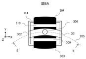
- the first injection unit 303 and the second injection unit 304 exemplified in FIGS. 6A and 6B spread the washing water in the direction of the nozzle trajectory 205 and inject it.
- the first injection unit 303 and the second injection unit 304 are configured such that a plurality of injection ports are arranged side by side in the direction of the nozzle trajectory 205, that is, in the horizontal direction, or the width in the horizontal direction is larger than the width in the vertical direction. Is composed of a wide-shaped injection port.
- the dispensing nozzle 210 moving in the horizontal direction can be washed more efficiently.
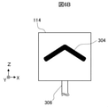
- the first injection unit 303 and the second injection unit 304 may inject cleaning water to a lower position as the dispensing nozzle 210 approaches the first opening 301 or the second opening 302.
- the position of the injection port in the central portion which is the farthest position from the first opening 301 and the second opening 302, is the highest, and the first opening 301 or the second opening 302 has the highest position.
- the position of the injection port is lowered as it approaches.
- the dispensing nozzle 210 approaches the outlet regardless of whether the dispensing nozzle 210 moves from the first opening 301 to the second opening 302 or in the opposite direction. As the washing water is sprayed to a lower position.
- the position of the injection port on the side of the first opening 301 is maximized to the second opening 302.
- the position of the injection port may be lowered as it approaches. Further, the method of lowering the position of the injection port is not limited to the linear one as illustrated in FIG. 6B, but is curved, for example, such that the injection port draws an upwardly convex arc shape. Is also good.
- the washing water is sprayed to a lower position, so that the dispensing nozzle 210 moving in the horizontal direction can be washed more efficiently.
- the time for drying the dispensing nozzle 210 can be shortened.
- Specimen container 101: Specimen container, 102: Specimen transport unit, 103: Nozzle container, 104: Nozzle storage, 105: Specimen dispensing unit, 106: Nozzle dispensing unit, 107: Reaction promoting unit, 108: Measuring unit, 109: Reaction Container transport unit, 110: Specimen suction position, 111: Consumables storage unit, 112: Consumables transport unit, 113: Control unit, 114: Nozzle cleaning tank, 115: Stirring unit, 116: Paddle cleaning tank, 201: Reagent discharge Position, 202: Nozzle cleaning position, 203a to 203c: Reagent suction port, 205: Nozzle trajectory, 207: Shaft, 208: Drive unit, 209: Arm, 210: Dispensing nozzle, 215: Liquid level sensor, 301: First Opening, 302: Second opening, 303: First injection part, 304: Second injection part, 305: Washing water, 306: Drain
Landscapes
- Physics & Mathematics (AREA)
- Health & Medical Sciences (AREA)
- Life Sciences & Earth Sciences (AREA)
- Chemical & Material Sciences (AREA)
- Analytical Chemistry (AREA)
- Biochemistry (AREA)
- General Health & Medical Sciences (AREA)
- General Physics & Mathematics (AREA)
- Immunology (AREA)
- Pathology (AREA)
- Automatic Analysis And Handling Materials Therefor (AREA)
Abstract
検体または試薬を分注する分注ノズルを洗浄槽にて上下動させることなく洗浄できる自動分析装置を提供する。検体または試薬を分注する分注ノズルと、前記分注ノズルを洗浄するノズル洗浄槽を備える自動分析装置であって、前記ノズル洗浄槽は、前記分注ノズルに洗浄水を噴射する噴射部と、前記分注ノズルが出入りする開口を有し、前記開口は、前記ノズル洗浄槽の側面に、前記分注ノズルの水平面内での軌道に沿って設けられることを特徴とする。
Description
本発明は、自動分析装置に関する。
自動分析装置は、血液や尿等の検体を試薬と反応させ、定量分析あるいは定性分析を自動的に実行する装置である。検体や試薬は、検体容器や試薬容器から分析用の反応容器へ分注ノズルによって分注される。分注ノズルは、検体用と試薬用とが設けられるものの、異なる検体や試薬に対して繰り返し使用されるので、分注する毎に洗浄水や圧縮空気の吹き付けによる洗浄・乾燥がなされ、清浄な状態に保たれる。ただし、洗浄後に圧縮空気を吹き付けるときに、分注ノズルに残存する洗浄水が自動分析装置内に飛散する場合がある。
特許文献1には、洗浄水を飛散させることなく分注ノズルを洗浄・乾燥するために、洗浄水や圧縮空気の分注ノズルへの吹き付けを行う洗浄槽において、分注ノズルが通過する上部開口よりも洗浄水を排出する下部開口を広くした自動分析装置が開示されている。
しかしながら特許文献1では、洗浄・乾燥される分注ノズルを洗浄槽にて上下動させる必要がある。分注ノズルを上下動させるには、分注ノズルの移動方向を水平方向と鉛直方向の間で切り替える必要があり、洗浄・乾燥の工程に時間を要する。
そこで、本発明は、分注ノズルを洗浄槽にて上下動させることなく洗浄できる自動分析装置を提供することを目的とする。
上記目的を達成するために本発明は、検体または試薬を分注する分注ノズルと、前記分注ノズルを洗浄するノズル洗浄槽を備える自動分析装置であって、前記ノズル洗浄槽は、前記分注ノズルに洗浄水を噴射する噴射部と、前記分注ノズルが出入りする開口を有し、前記開口は、前記ノズル洗浄槽の側面に、前記分注ノズルの水平面内での軌道に沿って設けられることを特徴とする。
本発明によれば、分注ノズルを洗浄槽にて上下動させることなく洗浄できる自動分析装置を提供することが可能となる。
以下、添付図面に従って本発明に係る自動分析装置の好ましい実施例について説明する。自動分析装置は、検体と試薬を反応させた反応液を用いて検体を分析する装置であり、例えば生化学自動分析装置、免疫自動分析装置や遺伝子自動分析装置等が挙げられる。また臨床検査に用いられる質量分析装置や血液の凝固時間を測定する凝固分析装置等も含まれる。さらに、質量分析装置や凝固分析装置等と生化学自動分析装置、免疫自動分析装置等との複合システム、またはこれらを応用した自動分析システムにも本発明は適用できる。
図1を用いて、本実施例の自動分析装置の全体構成の一例を説明する。自動分析装置は、検体搬送部102、試薬保管庫104、検体分注部105、試薬分注部106、反応促進部107、測定部108、制御部113を備える。以下、各部について説明する。なお、鉛直方向をZ方向、水平面をXY面とする。
検体搬送部102は、血液や尿等の検体が収容される検体容器101を検体吸引位置110まで搬送する。試薬保管庫104は、分析に使用される試薬を収容する試薬容器103を所定の温度範囲で保管する。
検体分注部105は、検体吸引位置110に搬送された検体容器101から反応促進部107に配置された反応容器へ検体を分注する。なお、検体が分注される反応容器と、検体の分注時に使用される分注チップとは消耗品保管部111に保管され、消耗品搬送部112によって所定の位置に搬送される。
試薬分注部106は、試薬保管庫104に保管される試薬容器103から反応促進部107に配置され検体が分注された反応容器へ試薬を分注する。試薬を分注した後、試薬分注部106は、ノズル洗浄槽114にて洗浄される。試薬分注部106の詳細については図2及び図3を用いて後述する。またノズル洗浄槽114の詳細については図4A及び図4Bを用いて後述する。なお試薬容器103の中の試薬が磁気ビーズ等を含む場合、試薬の分注に先立ち、先端に攪拌用のパドルを有する攪拌部115が試薬を撹拌する。攪拌部115は、試薬を撹拌した後、パドル洗浄槽116にて洗浄される。
反応促進部107は、検体と試薬が分注された反応容器を所定の温度範囲に保つことにより、反応容器内の検体と試薬との反応を促進させ反応液を生成する。反応促進部107が円盤形状である場合、円盤の中心軸を回転軸として回転することにより、検体分注部105が検体を吐出する位置や試薬分注部106が試薬を吐出する位置へ反応容器を移動させる。反応液を収容する反応容器は、反応容器搬送部109によって反応促進部107から測定部108へ搬送される。
測定部108は、反応容器搬送部109によって搬送された反応容器の中の反応液に対して光学的あるいは電気的な測定を行う。例えば反応液の吸光度や、試薬が添加された反応液に電圧を印加したときの発光量、反応液中の粒子数、反応液が電極膜に接触したときの電流値や電圧値の変動等が測定される。吸光度や発光量の測定には光電子増倍管や光度計等の測光器が、粒子数の計測にはCCDカメラ等の撮像素子が、電流値や電圧値の変動等の測定には電流計や電圧計がそれぞれ用いられる。
制御部113は、自動分析装置が備える各部を制御する装置であり、例えばコンピュータによって構成される。制御部113には入出力装置が接続され、入力装置、例えばキーボードやマウス、タッチパネル等を介して分析に必要なデータが入力されたり、出力装置、例えば液晶ディスプレイやタッチパネル等に分析結果が出力されたりする。
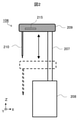
図2を用いて、試薬分注部106の一例について説明する。試薬分注部106は、駆動部208と、シャフト207、アーム209、分注ノズル210を備える。
駆動部208は、モータ等の駆動源を有し、駆動部208に接続されるシャフト207をZ軸方向に昇降させたり、Z軸周りで回転させたりする。シャフト207は円柱形状の棒であって、上端にはアーム209の一端が接続される。アーム209はシャフト207と分注ノズル210とをつなぐ部材であり、一端にシャフト207が、他端に分注ノズル210が接続される。
分注ノズル210は、試薬を吸引・吐出する細管である。分注ノズル210はアーム209を介してシャフト207に接続されるので、駆動部208によって昇降するシャフト207とともに上下動し、シャフト207の回転にともなって水平面であるXY面内で円弧軌道を描く。
なおアーム209の中には、分注ノズル210の先端に接する液面を検知する液面センサ215が格納される。液面センサ215の検知信号に基づいて、分注ノズル210の上下動の停止位置が決められたり、試薬容器103の中の液量が計測されたりする。また分注ノズル210の先端の変位を抑制するため、アーム209の長さをより短くし剛性を高めることが望ましい。短いアーム209は、試薬分注部106の軽量化による動作の高速化とともに、動作時の専有スペースを縮小できる。
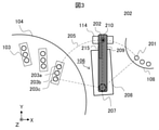
図3を用いて、試薬分注部106の配置の一例について説明する。前述のように試薬分注部106の分注ノズル210は、駆動部208がシャフト207を回転させることによって、点線で示される円弧軌道であるノズル軌道205を描く。
分注ノズル210はノズル軌道205において試薬を吸引・吐出するので、試薬が吸引される位置である試薬吸引口203a~203c及び試薬が吐出される位置である試薬吐出位置201にノズル軌道205が重なるように、試薬分注部106は配置される。また分注ノズル210の移動距離がより短くなるように、反応促進部107と試薬保管庫104の間に試薬分注部106が配置されることが望ましい。さらに、分注ノズル210が洗浄される位置であるノズル洗浄位置202がノズル軌道205に重なるように、ノズル洗浄槽114が配置される。分注ノズル210の移動距離がより短くなるように、ノズル洗浄槽114も反応促進部107と試薬保管庫104の間に配置されることが望ましい。
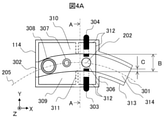
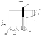
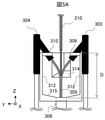
図4A及び図4Bを用いて、ノズル洗浄槽114の一例について説明する。ノズル洗浄槽114は、第一開口301と第二開口302及び第一噴射部303と第二噴射部304を有する。
第一開口301と第二開口302は、分注ノズル210がノズル軌道205に沿って移動するときに、ノズル洗浄槽114に出入りする開口であって、ノズル洗浄槽114の側面に設けられる。分注ノズル210が出入りする開口である第一開口301と第二開口302は、分注ノズル210の水平面内での軌道であるノズル軌道205に沿って設けられる。
第一噴射部303と第二噴射部304は、分注ノズル210の洗浄に用いられる洗浄水をノズル洗浄位置202に向けて噴射する。分注ノズル210を洗浄した洗浄水は、排水管306を介して自動分析装置の外へ排出される。第一噴射部303と第二噴射部304は互いに対向して配置されることが望ましい。第一噴射部303と第二噴射部304が対向配置されることにより、円筒形状である分注ノズル210の両側面に同時に洗浄水が噴射され、分注ノズル210の外壁全面が洗浄される。
第一噴射部303と第二噴射部304は、洗浄水を常に噴射し続けていても良いし、分注ノズル210がノズル洗浄位置202に達したときに洗浄水を噴射しても良い。洗浄水が噴射し続けられる場合は、分注ノズル210がノズル洗浄位置202に停止せずとも洗浄がなされるので、洗浄工程をより短縮できる。分注ノズル210がノズル洗浄位置202に達したときに洗浄水が噴射される場合は、分注ノズル210をノズル洗浄位置202に停止させる必要はあるものの洗浄水を節約できる。
また第一噴射部303と第二噴射部304から噴射される洗浄水の水圧の差異は、より小さいことが望ましい。水圧の差異が著しく大きいと水圧が低い側に水滴が残留しやすくなるのに対し、水圧の差異がより小さければ洗浄後の分注ノズル210に残留する水滴を低減できる。そのため、分注ノズル210をノズル洗浄位置202にて停止させることなく洗浄する場合は、ノズル軌道205に直交する方向から洗浄水が噴射されることが望ましい。なお、残留する水滴をより低減するために、分注ノズル210の外表面に撥水処理が施されても良い。
また第一噴射部303と第二噴射部304から噴射される洗浄水の水圧の差異は、より小さいことが望ましい。水圧の差異が著しく大きいと水圧が低い側に水滴が残留しやすくなるのに対し、水圧の差異がより小さければ洗浄後の分注ノズル210に残留する水滴を低減できる。そのため、分注ノズル210をノズル洗浄位置202にて停止させることなく洗浄する場合は、ノズル軌道205に直交する方向から洗浄水が噴射されることが望ましい。なお、残留する水滴をより低減するために、分注ノズル210の外表面に撥水処理が施されても良い。
分注ノズル210に噴射された洗浄水は、ノズル洗浄槽114から飛散する場合ある。飛散した洗浄水には試薬等が含まれるので、飛散した水滴によって自動分析装置が汚染されると分析結果に悪影響を及ぼす。そこで、洗浄水の飛散を抑制するために、第一開口301や第二開口302の位置を第一噴射部303と第二噴射部304から遠ざけるための延伸部313や、ノズル軌道205の両側を覆う第一屋根309と第二屋根310が設けられても良い。
図4A及び図4Bを用いて、延伸部313について説明する。延伸部313は第一開口301を第一噴射部303と第二噴射部304から遠ざけるために、ノズル軌道205に沿って伸びる壁面である。延伸部313がノズル軌道205に沿って伸びることにより、洗浄水の噴射方向と直交する方向、すなわち図4AにおけるX軸方向からの見込み幅Cを分注ノズル210が通過する開口の幅Bよりも狭くすることができる。見込み幅Cが開口の幅Bよりも狭くなることにより、ノズル洗浄位置202からX軸方向に直線的に飛散する水滴を抑制することができる。見込み幅Cはノズル軌道205の径が短くなるほど狭くなり、ノズル軌道205の径は、反応促進部107や試薬保管庫104、試薬分注部106の配置に依るので、三者の配置はノズル軌道205の径が短くなるように設定されることが望ましい。
また延伸部313の底面314は、ノズル洗浄槽114に向かって傾斜する傾斜面であることが望ましい。底面314が傾斜面であることにより、延伸部313に飛散した水滴はノズル洗浄槽114に向かって流れ、排水管306を介して排出される。なお図4A及び図4Bに例示される延伸部313は、第一開口301の側だけでなく第二開口302の側に設けられても良い。
さらに開口の幅Bに相当する延伸部313の幅は、ノズル洗浄槽114の幅、すなわちY方向の長さよりも狭いことが望ましい。延伸部313の幅がノズル洗浄槽114の幅よりも狭いことにより、洗浄水はノズル洗浄槽114の外へ飛散しにくくなる。
図5Aを用いて、第一屋根309と第二屋根310の一例について説明する。第一屋根309と第二屋根310は、第一噴射部303と第二噴射部304が洗浄水305を噴射する高さよりも高い位置に設けられる。洗浄水305が噴射される高さよりも高い位置であってノズル軌道205の両側に第一屋根309と第二屋根310が設けられることによって、分注ノズル210に噴射された洗浄水305の飛散が抑制される。
なお第一屋根309または第二屋根310から底部315までの距離Dはより長いことが望ましい。距離Dが長いほど、底部315から跳ね上がる水滴がノズル洗浄槽114の外へ飛散しにくくなる。また底部315は、排水管306に向かって傾斜することが望ましい。底部315が傾斜することによって、洗浄後の洗浄水は底部315に滞留せずに排水管306へ流れるので、底部315に滞留する洗浄水が跳ね上がらずに済む。
図5Bを用いて、第一屋根309と第二屋根310の他の例について説明する。図5Bに示される第一屋根309と第二屋根310の下面は、ノズル軌道205に近い側がノズル軌道205から遠い側よりも高い傾斜面である。第一屋根309と第二屋根310の下面に付着した水滴は、傾斜面に沿ってノズル洗浄槽114の内壁312の側へ流れるので、洗浄された分注ノズル210を汚さずに済む。
なお、図5A及び図5Bに例示される第一屋根309と第二屋根310は、図4Aに示されるようにノズル軌道205を覆うことなく設けられるので、分注ノズル210の水平移動を妨げない。またノズル洗浄槽114には、内壁洗浄部307とノズル退避部308がさらに設けられても良い。なお、内壁洗浄部307及びノズル退避部308は、仕切り壁311によって、第一噴射部303及び第二噴射部304から隔離されることが望ましい。仕切り壁311によって隔離されることにより、内壁洗浄部307及びノズル退避部308は飛散する水滴を避けて清浄な状態に保たれる。
内壁洗浄部307は、分注ノズル210の内壁を洗浄するための試薬が湧き出す容器である。内壁洗浄部307では、湧き出た試薬に先端を浸漬させた分注ノズル210によって、規定量の試薬が吸引される。そして試薬を吸引した分注ノズル210が排水管306へ試薬を吐出することで分注ノズル210の内壁の洗浄が完了する。
ノズル退避部308は、自動分析装置のメンテナンス時に分注ノズル210が格納される筒である。ノズル退避部308に分注ノズル210が格納されることにより、装置ユーザーやサービスマンが分注ノズル210に誤って接触し、分注ノズル210を破損させることを防止できる。
図6A及び図6Bを用いて、第一噴射部303と第二噴射部304の変形例について説明する。図6A及び図6Bに例示される第一噴射部303と第二噴射部304は、洗浄水をノズル軌道205の方向に広げて噴射する。具体的には、第一噴射部303と第二噴射部304は、複数の噴射口がノズル軌道205の方向、すなわち水平方向に並べられて構成されたり、鉛直方向の幅よりも水平方向の幅が広い形状の噴射口で構成されたりする。洗浄水がノズル軌道205の方向に広げられて噴射されることにより、水平方向に移動中の分注ノズル210をより効率的に洗浄することができる。なお分注ノズル210の両側面における水圧の差異をより小さくするため、ノズル軌道205に直交する方向から洗浄水が噴射されることが望ましい。
また第一噴射部303と第二噴射部304は、分注ノズル210が第一開口301又は第二開口302に近づくにつれて、より低い位置に洗浄水を噴射するようにしても良い。具体的には、図6Bに示されるように、第一開口301及び第二開口302から最も遠い位置である中央部における噴射口の位置が最高であり、第一開口301又は第二開口302に近づくにつれて噴射口の位置が下げられる。図6Bに例示される噴射口の配置であれば、分注ノズル210が第一開口301から第二開口302へ移動する場合でも、逆方向に移動する場合でも、分注ノズル210が出口に近づくにつれて、洗浄水がより低い位置に噴射される。
なお分注ノズル210の移動方向が第一開口301から第二開口302への一方向に限られるのであれば、第一開口301の側の噴射口の位置を最高にして、第二開口302に近づくにつれて噴射口の位置を下げても良い。また噴射口の位置の下げ方は、図6Bに例示されるような直線的なものに限定されず、曲線的なもの、例えば上に凸な円弧形状を噴射口が描くようなものであっても良い。
分注ノズル210が第一開口301又は第二開口302に近づくにつれて、洗浄水がより低い位置に噴射されることにより、水平方向に移動中の分注ノズル210をより効率的に洗浄できるとともに、分注ノズル210を乾燥させる時間を短縮できる。
以上、本発明の実施例について説明した。本発明は上記実施例に限定されるものではなく、発明の要旨を逸脱しない範囲で構成要素を変形しても良い。また、上記実施例に開示されている複数の構成要素を適宜組み合わせても良い。さらに、上記実施例に示される全構成要素からいくつかの構成要素を削除しても良い。
101:検体容器、102:検体搬送部、103:試薬容器、104:試薬保管庫、105:検体分注部、106:試薬分注部、107:反応促進部、108:測定部、109:反応容器搬送部、110:検体吸引位置、111:消耗品保管部、112:消耗品搬送部、113:制御部、114:ノズル洗浄槽、115:攪拌部、116:パドル洗浄槽、201:試薬吐出位置、202:ノズル洗浄位置、203a~203c:試薬吸引口、205:ノズル軌道、207:シャフト、208:駆動部、209:アーム、210:分注ノズル、215:液面センサ、301:第一開口、302:第二開口、303:第一噴射部、304:第二噴射部、305:洗浄水、306:排水管、307:内壁洗浄部、308:ノズル退避部、309:第一屋根、310:第二屋根、311:仕切り壁、312:内壁、313:延伸部、314:底面、315:底部
Claims (10)
- 検体または試薬を分注する分注ノズルと、
前記分注ノズルを洗浄するノズル洗浄槽を備える自動分析装置であって、
前記ノズル洗浄槽は、前記分注ノズルに洗浄水を噴射する噴射部と、前記分注ノズルが出入りする開口を有し、
前記開口は、前記ノズル洗浄槽の側面に、前記分注ノズルの水平面内での軌道に沿って設けられることを特徴とする自動分析装置。 - 請求項1に記載の自動分析装置であって、
前記ノズル洗浄槽は、前記噴射部が前記洗浄水を噴射する高さよりも高い位置に設けられ、前記軌道の両側を覆う屋根をさらに有することを特徴とする自動分析装置。 - 請求項2に記載の自動分析装置であって、
前記屋根の下面は、前記軌道に近い側が前記軌道から遠い側よりも高い傾斜面であることを特徴とする自動分析装置。 - 請求項1に記載の自動分析装置であって、
前記開口は、前記軌道に沿って伸びる延伸部を有することを特徴とする自動分析装置。 - 請求項4に記載の自動分析装置であって、
前記延伸部の底面は、前記ノズル洗浄槽に向かって傾斜する傾斜面であることを特徴とする自動分析装置。 - 請求項4に記載の自動分析装置であって、
前記延伸部の幅は、前記ノズル洗浄槽の幅よりも狭いことを特徴とする自動分析装置。 - 請求項1に記載の自動分析装置であって、
前記噴射部は、前記軌道に直交する方向から前記洗浄水を噴射することを特徴とする自動分析装置。 - 請求項7に記載の自動分析装置であって、
前記噴射部は前記洗浄水を前記軌道の方向に広げて噴射することを特徴とする自動分析装置。 - 請求項8に記載の自動分析装置であって、
前記噴射部は、前記分注ノズルが前記開口に近づくにつれて、前記洗浄水をより低い位置に噴射することを特徴とする自動分析装置。 - 請求項1に記載の自動分析装置であって、
前記軌道は円弧形状であることを特徴とする自動分析装置。
Priority Applications (4)
| Application Number | Priority Date | Filing Date | Title |
|---|---|---|---|
| US18/013,357 US20230341432A1 (en) | 2020-07-22 | 2021-02-12 | Automatic Analyzer |
| EP21844618.5A EP4187255A1 (en) | 2020-07-22 | 2021-02-12 | Automated analyzer |
| CN202180045582.3A CN115803637A (zh) | 2020-07-22 | 2021-02-12 | 自动分析装置 |
| JP2022538578A JP7433440B2 (ja) | 2020-07-22 | 2021-02-12 | 自動分析装置 |
Applications Claiming Priority (2)
| Application Number | Priority Date | Filing Date | Title |
|---|---|---|---|
| JP2020-124999 | 2020-07-22 | ||
| JP2020124999 | 2020-07-22 |
Publications (1)
| Publication Number | Publication Date |
|---|---|
| WO2022018895A1 true WO2022018895A1 (ja) | 2022-01-27 |
Family
ID=79729365
Family Applications (1)
| Application Number | Title | Priority Date | Filing Date |
|---|---|---|---|
| PCT/JP2021/005309 WO2022018895A1 (ja) | 2020-07-22 | 2021-02-12 | 自動分析装置 |
Country Status (5)
| Country | Link |
|---|---|
| US (1) | US20230341432A1 (ja) |
| EP (1) | EP4187255A1 (ja) |
| JP (1) | JP7433440B2 (ja) |
| CN (1) | CN115803637A (ja) |
| WO (1) | WO2022018895A1 (ja) |
Citations (6)
| Publication number | Priority date | Publication date | Assignee | Title |
|---|---|---|---|---|
| JPH05126836A (ja) * | 1991-10-31 | 1993-05-21 | Toshiba Corp | プローブ洗浄槽 |
| JPH11271321A (ja) * | 1998-03-23 | 1999-10-08 | Olympus Optical Co Ltd | 洗浄装置 |
| JP2005241442A (ja) * | 2004-02-26 | 2005-09-08 | Olympus Corp | 洗浄装置、洗浄装置を用いた分析装置及び洗浄方法 |
| JP2012167998A (ja) * | 2011-02-14 | 2012-09-06 | Toshiba Corp | 洗浄装置および自動分析装置 |
| JP2013134142A (ja) | 2011-12-26 | 2013-07-08 | Hitachi High-Technologies Corp | 自動分析装置 |
| US20190041414A1 (en) * | 2017-08-01 | 2019-02-07 | Euroimmun Medizinische Labordiagnostika Ag | Apparatus and method for cleaning pipetting needles |
-
2021
- 2021-02-12 WO PCT/JP2021/005309 patent/WO2022018895A1/ja unknown
- 2021-02-12 US US18/013,357 patent/US20230341432A1/en active Pending
- 2021-02-12 JP JP2022538578A patent/JP7433440B2/ja active Active
- 2021-02-12 EP EP21844618.5A patent/EP4187255A1/en active Pending
- 2021-02-12 CN CN202180045582.3A patent/CN115803637A/zh active Pending
Patent Citations (6)
| Publication number | Priority date | Publication date | Assignee | Title |
|---|---|---|---|---|
| JPH05126836A (ja) * | 1991-10-31 | 1993-05-21 | Toshiba Corp | プローブ洗浄槽 |
| JPH11271321A (ja) * | 1998-03-23 | 1999-10-08 | Olympus Optical Co Ltd | 洗浄装置 |
| JP2005241442A (ja) * | 2004-02-26 | 2005-09-08 | Olympus Corp | 洗浄装置、洗浄装置を用いた分析装置及び洗浄方法 |
| JP2012167998A (ja) * | 2011-02-14 | 2012-09-06 | Toshiba Corp | 洗浄装置および自動分析装置 |
| JP2013134142A (ja) | 2011-12-26 | 2013-07-08 | Hitachi High-Technologies Corp | 自動分析装置 |
| US20190041414A1 (en) * | 2017-08-01 | 2019-02-07 | Euroimmun Medizinische Labordiagnostika Ag | Apparatus and method for cleaning pipetting needles |
Also Published As
| Publication number | Publication date |
|---|---|
| JPWO2022018895A1 (ja) | 2022-01-27 |
| JP7433440B2 (ja) | 2024-02-19 |
| EP4187255A1 (en) | 2023-05-31 |
| CN115803637A (zh) | 2023-03-14 |
| US20230341432A1 (en) | 2023-10-26 |
Similar Documents
| Publication | Publication Date | Title |
|---|---|---|
| JP5744923B2 (ja) | 自動分析装置 | |
| US11231433B2 (en) | Automatic analyzer and cleaning method | |
| US9804184B2 (en) | Automated analyzer and method for lifting and lowering rod-like member in automated analyzer | |
| JP2009042067A (ja) | 自動分析装置 | |
| JP5236612B2 (ja) | 自動分析装置 | |
| JPH1062431A (ja) | 生化学自動分析装置における洗浄装置 | |
| JP2005241442A (ja) | 洗浄装置、洗浄装置を用いた分析装置及び洗浄方法 | |
| CN110320380B (zh) | 自动分析装置和自动分析方法 | |
| JP4977582B2 (ja) | 自動分析装置 | |
| JP5661259B2 (ja) | 自動分析装置 | |
| JP2008224244A (ja) | 洗浄装置および自動分析装置 | |
| WO2022018895A1 (ja) | 自動分析装置 | |
| JP4175916B2 (ja) | 自動分析装置 | |
| CN114729954A (zh) | 自动分析装置 | |
| CN112689764A (zh) | 自动分析装置 | |
| JP2005249585A (ja) | 自動分析装置及び分析方法 | |
| US11879902B2 (en) | Test method and dispensing device | |
| JP6355960B2 (ja) | 臨床検査装置及び容器の洗浄方法 | |
| JP2012026786A (ja) | 自動分析装置 | |
| JP2007309742A (ja) | 自動分析装置 | |
| JPH08101214A (ja) | 臨床用自動分析装置 | |
| JPWO2019176296A1 (ja) | 自動分析装置 | |
| JP7154407B2 (ja) | 自動分析装置 | |
| JP5124497B2 (ja) | 自動分析装置 | |
| JP7167037B2 (ja) | 自動分析装置および検体分注機構の異常検出方法 |
Legal Events
| Date | Code | Title | Description |
|---|---|---|---|
| 121 | Ep: the epo has been informed by wipo that ep was designated in this application |
Ref document number: 21844618 Country of ref document: EP Kind code of ref document: A1 |
|
| ENP | Entry into the national phase |
Ref document number: 2022538578 Country of ref document: JP Kind code of ref document: A |
|
| NENP | Non-entry into the national phase |
Ref country code: DE |
|
| ENP | Entry into the national phase |
Ref document number: 2021844618 Country of ref document: EP Effective date: 20230222 |