WO2022014491A1 - 豆腐類製造装置及び豆腐類製造方法 - Google Patents
豆腐類製造装置及び豆腐類製造方法 Download PDFInfo
- Publication number
- WO2022014491A1 WO2022014491A1 PCT/JP2021/025947 JP2021025947W WO2022014491A1 WO 2022014491 A1 WO2022014491 A1 WO 2022014491A1 JP 2021025947 W JP2021025947 W JP 2021025947W WO 2022014491 A1 WO2022014491 A1 WO 2022014491A1
- Authority
- WO
- WIPO (PCT)
- Prior art keywords
- coagulant
- coagulation tank
- tofu
- soymilk
- continuous
- Prior art date
- Legal status (The legal status is an assumption and is not a legal conclusion. Google has not performed a legal analysis and makes no representation as to the accuracy of the status listed.)
- Ceased
Links
Images


Classifications
-
- A—HUMAN NECESSITIES
- A23—FOODS OR FOODSTUFFS; TREATMENT THEREOF, NOT COVERED BY OTHER CLASSES
- A23P—SHAPING OR WORKING OF FOODSTUFFS, NOT FULLY COVERED BY A SINGLE OTHER SUBCLASS
- A23P30/00—Shaping or working of foodstuffs characterised by the process or apparatus
- A23P30/10—Moulding
-
- A—HUMAN NECESSITIES
- A23—FOODS OR FOODSTUFFS; TREATMENT THEREOF, NOT COVERED BY OTHER CLASSES
- A23L—FOODS, FOODSTUFFS OR NON-ALCOHOLIC BEVERAGES, NOT OTHERWISE PROVIDED FOR; PREPARATION OR TREATMENT THEREOF
- A23L11/00—Pulses, i.e. fruits of leguminous plants, for production of food; Products from legumes; Preparation or treatment thereof
- A23L11/40—Pulse curds
- A23L11/45—Soy bean curds, e.g. tofu
-
- A—HUMAN NECESSITIES
- A23—FOODS OR FOODSTUFFS; TREATMENT THEREOF, NOT COVERED BY OTHER CLASSES
- A23P—SHAPING OR WORKING OF FOODSTUFFS, NOT FULLY COVERED BY A SINGLE OTHER SUBCLASS
- A23P30/00—Shaping or working of foodstuffs characterised by the process or apparatus
-
- B—PERFORMING OPERATIONS; TRANSPORTING
- B65—CONVEYING; PACKING; STORING; HANDLING THIN OR FILAMENTARY MATERIAL
- B65G—TRANSPORT OR STORAGE DEVICES, e.g. CONVEYORS FOR LOADING OR TIPPING, SHOP CONVEYOR SYSTEMS OR PNEUMATIC TUBE CONVEYORS
- B65G15/00—Conveyors having endless load-conveying surfaces, i.e. belts and like continuous members, to which tractive effort is transmitted by means other than endless driving elements of similar configuration
- B65G15/10—Conveyors having endless load-conveying surfaces, i.e. belts and like continuous members, to which tractive effort is transmitted by means other than endless driving elements of similar configuration comprising two or more co-operating endless surfaces with parallel longitudinal axes, or a multiplicity of parallel elements, e.g. ropes defining an endless surface
- B65G15/12—Conveyors having endless load-conveying surfaces, i.e. belts and like continuous members, to which tractive effort is transmitted by means other than endless driving elements of similar configuration comprising two or more co-operating endless surfaces with parallel longitudinal axes, or a multiplicity of parallel elements, e.g. ropes defining an endless surface with two or more endless belts
- B65G15/14—Conveyors having endless load-conveying surfaces, i.e. belts and like continuous members, to which tractive effort is transmitted by means other than endless driving elements of similar configuration comprising two or more co-operating endless surfaces with parallel longitudinal axes, or a multiplicity of parallel elements, e.g. ropes defining an endless surface with two or more endless belts the load being conveyed between the belts
-
- B—PERFORMING OPERATIONS; TRANSPORTING
- B65—CONVEYING; PACKING; STORING; HANDLING THIN OR FILAMENTARY MATERIAL
- B65G—TRANSPORT OR STORAGE DEVICES, e.g. CONVEYORS FOR LOADING OR TIPPING, SHOP CONVEYOR SYSTEMS OR PNEUMATIC TUBE CONVEYORS
- B65G15/00—Conveyors having endless load-conveying surfaces, i.e. belts and like continuous members, to which tractive effort is transmitted by means other than endless driving elements of similar configuration
- B65G15/30—Belts or like endless load-carriers
- B65G15/32—Belts or like endless load-carriers made of rubber or plastics
- B65G15/42—Belts or like endless load-carriers made of rubber or plastics having ribs, ridges, or other surface projections
-
- B—PERFORMING OPERATIONS; TRANSPORTING
- B65—CONVEYING; PACKING; STORING; HANDLING THIN OR FILAMENTARY MATERIAL
- B65G—TRANSPORT OR STORAGE DEVICES, e.g. CONVEYORS FOR LOADING OR TIPPING, SHOP CONVEYOR SYSTEMS OR PNEUMATIC TUBE CONVEYORS
- B65G19/00—Conveyors comprising an impeller or a series of impellers carried by an endless traction element and arranged to move articles or materials over a supporting surface or underlying material, e.g. endless scraper conveyors
- B65G19/02—Conveyors comprising an impeller or a series of impellers carried by an endless traction element and arranged to move articles or materials over a supporting surface or underlying material, e.g. endless scraper conveyors for articles, e.g. for containers
-
- B—PERFORMING OPERATIONS; TRANSPORTING
- B65—CONVEYING; PACKING; STORING; HANDLING THIN OR FILAMENTARY MATERIAL
- B65G—TRANSPORT OR STORAGE DEVICES, e.g. CONVEYORS FOR LOADING OR TIPPING, SHOP CONVEYOR SYSTEMS OR PNEUMATIC TUBE CONVEYORS
- B65G19/00—Conveyors comprising an impeller or a series of impellers carried by an endless traction element and arranged to move articles or materials over a supporting surface or underlying material, e.g. endless scraper conveyors
- B65G19/04—Conveyors comprising an impeller or a series of impellers carried by an endless traction element and arranged to move articles or materials over a supporting surface or underlying material, e.g. endless scraper conveyors for moving bulk material in open troughs or channels
- B65G19/06—Conveyors comprising an impeller or a series of impellers carried by an endless traction element and arranged to move articles or materials over a supporting surface or underlying material, e.g. endless scraper conveyors for moving bulk material in open troughs or channels the impellers being scrapers similar in size and shape to the cross-section of the trough or channel
- B65G19/08—Conveyors comprising an impeller or a series of impellers carried by an endless traction element and arranged to move articles or materials over a supporting surface or underlying material, e.g. endless scraper conveyors for moving bulk material in open troughs or channels the impellers being scrapers similar in size and shape to the cross-section of the trough or channel and attached to a single belt, rope or chain
-
- B—PERFORMING OPERATIONS; TRANSPORTING
- B65—CONVEYING; PACKING; STORING; HANDLING THIN OR FILAMENTARY MATERIAL
- B65G—TRANSPORT OR STORAGE DEVICES, e.g. CONVEYORS FOR LOADING OR TIPPING, SHOP CONVEYOR SYSTEMS OR PNEUMATIC TUBE CONVEYORS
- B65G19/00—Conveyors comprising an impeller or a series of impellers carried by an endless traction element and arranged to move articles or materials over a supporting surface or underlying material, e.g. endless scraper conveyors
- B65G19/18—Details
- B65G19/22—Impellers, e.g. push-plates, scrapers; Guiding means therefor
-
- B—PERFORMING OPERATIONS; TRANSPORTING
- B65—CONVEYING; PACKING; STORING; HANDLING THIN OR FILAMENTARY MATERIAL
- B65G—TRANSPORT OR STORAGE DEVICES, e.g. CONVEYORS FOR LOADING OR TIPPING, SHOP CONVEYOR SYSTEMS OR PNEUMATIC TUBE CONVEYORS
- B65G2201/00—Indexing codes relating to handling devices, e.g. conveyors, characterised by the type of product or load being conveyed or handled
- B65G2201/02—Articles
- B65G2201/0202—Agricultural and processed food products
-
- B—PERFORMING OPERATIONS; TRANSPORTING
- B65—CONVEYING; PACKING; STORING; HANDLING THIN OR FILAMENTARY MATERIAL
- B65G—TRANSPORT OR STORAGE DEVICES, e.g. CONVEYORS FOR LOADING OR TIPPING, SHOP CONVEYOR SYSTEMS OR PNEUMATIC TUBE CONVEYORS
- B65G2812/00—Indexing codes relating to the kind or type of conveyors
- B65G2812/01—Conveyors composed of several types of conveyors
- B65G2812/016—Conveyors composed of several types of conveyors for conveying material by co-operating units in tandem
- B65G2812/018—Conveyors composed of several types of conveyors for conveying material by co-operating units in tandem between conveyor sections
Definitions
- the present invention relates to a tofu manufacturing apparatus and a tofu manufacturing method having a continuous coagulator and a continuous molding machine.
- Patent Documents 1 to 4 describe that the tofu seeds obtained by coagulating soymilk are sent to the automatic molding section via the charging port in the automatic coagulation section.
- Patent Document 1 extreme crushing of tofu does not give a good quality product, and tofu seeds are not crushed as much as possible to make a thick and long tofu. It is stated that the amount of tofu seeds is quantified with a balanced weighted damper at the inlet.
- Patent Documents 1 and 2 since the automatic solidifying portion has a two-story structure arranged above the upper caterpillar of the automatic molding portion, the difference between the automatic solidifying portion and the automatic molding portion is considerable. The tofu crumbles not a little. In addition, when tofu is fed with a damper, the input port opens wide when a large amount of tofu is dropped, and the input port closes when a small amount of tofu is dropped, even though it has the effect of alleviating fluctuations in the input amount, especially soybean quality. If there is a change in the firmness of tofu due to changes, it is poorly quantitative.
- the present invention has been made in view of the above-mentioned problems, and can be supplied from a continuous coagulant onto the lower cloth of a continuous molding machine without breaking the soymilk coagulant while ensuring quantitativeness.
- the present invention is to provide a tofu manufacturing apparatus and a tofu manufacturing method.
- a boat-shaped continuous coagulator having an endless conveyor in which a plurality of partition blades are attached to the surface of a conveyor belt at predetermined intervals, and a coagulation tank having a concave cross section through which the partition blades pass inside.
- a continuous molding machine having at least a lower endless conveyor on which the lower cloth is wound and an upper endless conveyor on which the upper cloth is wound. It is a tofu manufacturing equipment with The lower endless conveyor overlaps the coagulation tank when viewed from above so that the lower cloth is located below the outlet end of the coagulation tank.
- the bottom wall of the coagulation tank is a tofu manufacturing apparatus formed substantially horizontally from the vicinity of the inlet of the coagulation tank toward the end of the coagulation tank.
- the tofu manufacturing apparatus according to (1) wherein the coagulation tank and the upper endless transport conveyor are arranged side by side in a straight line.
- the endless conveyor of the continuous coagulator inclines upward toward the feed direction of the continuous coagulator so that the tip or the mounting end of the partition blade rises near the outlet of the coagulation tank.
- the continuous coagulant puts soymilk, a coagulant, and soymilk containing a coagulant or a cleaning agent solution on at least one of the side walls and the bottom wall of the coagulant near the inlet of the coagulant.
- the tofu manufacturing apparatus according to any one of (1) to (3), which has a supply port for supplying or a discharge port for discharging them.
- the tofu manufacturing apparatus according to any one of (1) to (8), wherein the width of the coagulation tank is substantially equal to the width of the press portion of the continuous molding machine.
- a breaking device is provided between the coagulation tank and the upper endless transport conveyor above the lower cloth of the lower endless transport conveyor. At a position below the breaking device, a protective plate with which the breaking device can come into contact is arranged.
- the tofu manufacturing apparatus according to any one of (1) to (9), wherein the lower cloth of the lower endless transport conveyor is pushed down and guided so as to bypass the protective plate.
- the continuous coagulator further includes a cover that covers the upper part of the endless conveyor.
- any of (1) to (11), wherein the chain connecting the conveyor belt and the sprocket to which the chain is hung are arranged on the outer side in the width direction of the side wall of the solidification tank.
- the tofu manufacturing equipment described in Crab. (13) A tofu manufacturing method for producing tofu using the tofu manufacturing apparatus according to any one of (1) to (12).
- the continuous coagulator produces almost purine-like soymilk coagulant by coagulating and aging soymilk at 50 to 95 ° C. and a solid content of 3 to 20% wt with a coagulant.
- the continuous molding machine is a method for producing tofu, in which the soymilk coagulant is conveyed by the lower cloth and pressed as necessary to mold the tofu.
- the "almost purine-like soymilk coagulant” refers to a state of the coagulated product after coagulation and aging, in which the water separation is 20% or less, preferably 10% or less.
- the soymilk coagulated product can be supplied from the continuous coagulant onto the lower cloth of the continuous molding machine while ensuring the quantitativeness.
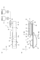
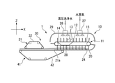
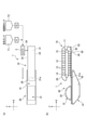
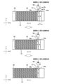
- (A) is a schematic top view showing a tofu manufacturing apparatus according to the first embodiment of the present invention
- (b) is a schematic side view of (a).
- FIG. 1 It is a schematic side view which shows the tofu manufacturing apparatus which concerns on 5th modification of 1st Embodiment of this invention. It is a schematic side view which shows the tofu manufacturing apparatus which concerns on the 6th modification of 1st Embodiment of this invention.
- (A) is a schematic side view corresponding to VIII-VIII of FIG. 1, showing a tofu manufacturing apparatus according to an example of a seventh modification of the first embodiment of the present invention, and (b) is the present invention.
- FIG. 1 It is a schematic side view corresponding to VIII-VIII of FIG. 1, which shows the tofu production apparatus which concerns on another example of 7th modification of 1st Embodiment of.
- FIG. 9 is a cross-sectional view of the vicinity of the inlet of the continuous coagulator of FIG. 9, where (a) shows a state in which the supply port is closed, and (b) shows a state in which the supply port is open. It is sectional drawing near the inlet of the continuous coagulant in the tofu manufacturing apparatus which concerns on 1st modification of 2nd Embodiment of this invention, (a) shows the state which the supply port is closed, (b). Indicates that the supply port is open.
- the feed portion of the coagulation tank of the continuous coagulator showing the process of supplying soymilk containing a coagulant to the continuous coagulant using a switching three-way valve.
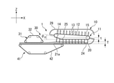
- A is a schematic top view showing a tofu manufacturing apparatus according to a third embodiment of the present invention
- (b) is a schematic side view of (a)
- (c) is (b). It is an enlarged view of the XV part.
- (A) is a figure corresponding to the XV part of FIG.
- the tofu manufacturing apparatus 1 of the first embodiment coagulates and matures soymilk containing a coagulant in which soymilk and a coagulant are mixed by a mixer 2 to produce a pudding-like soymilk coagulant.
- a boat-shaped continuous coagulator 10 and a continuous molding machine 30 for molding soymilk coagulant into tofu while dehydrating it are provided.
- the soymilk and the coagulant are sent from the stored soymilk tank T1 and the coagulant tank T2 at a predetermined flow rate by the metering pumps P1 and P2, mixed by the mixer 2, and sent to the continuous coagulant 10 as soymilk containing the coagulant. Will be supplied.
- the soymilk and the coagulant may be directly supplied separately to the continuous coagulant 10 and mixed in the coagulation tank 20. In any case, it is preferable that the majority (50% or more of the soymilk containing the coagulant in one section) is supplied below the liquid surface.
- the tofu manufacturing apparatus 1 of the present embodiment has a continuous coagulator 10 so that the continuous coagulant 10 feeds the soymilk containing the coagulant and the continuous molding machine 30 feeds the soymilk coagulant in the same direction.
- the continuous molding machine 30 and the continuous molding machine 30 are arranged side by side in a straight line. Although the installation space is widened, the soft, almost pudding-like coagulum can be transferred quantitatively without breaking it too much.
- the horizontal direction in which the continuous coagulator 10 and the continuous molding machine 30 are lined up is the X direction
- the width direction of the continuous coagulator 10 and the continuous molding machine 30, which is the horizontal direction orthogonal to the X direction is the Y direction, and is continuous.
- the vertical direction of the coagulator 10 and the continuous molding machine 30 is the Z direction.
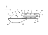
- the boat-shaped continuous coagulator 10 is made of an endless conveyor 11 on which a plurality of partition blades 13 are attached to the surface of a conveyor belt (endless chain) 12 at predetermined intervals, and a stainless steel having a concave cross section through which the partition blades 13 pass through. It mainly has a coagulation tank 20 and a cover 29 that covers the upper part of the endless conveyor 11.
- the conveyor belt (endless chain) 12 is hung around the two rollers 14 and 15 arranged substantially horizontally in the vicinity of the inlet and the outlet of the coagulation tank 20, and the two rollers 14 ,.
- the rotation of 15 orbits the conveyor belt (endless chain) 12 and the plurality of partition blades 13.
- the conveyor belt (endless chain) 12 of the continuous coagulator 10 is not particularly limited as long as it is a steel belt, a rigid metal belt such as stainless steel or titanium, a chain, or a wire and can fix a large number of partition blades.
- the plurality of partition blades 13 are composed of a metal steel plate member 13 such as stainless steel or titanium and a rubber member 13b, and have a rectangular shape that is long in the width direction and short in the vertical direction, and is a liquid such as soy milk or "yu".
- a rubber sealing member 13b such as flexible NBR, EPDM, FKM, etc. (fluororubber), silicon rubber, etc., inscribes or contacts the bottom wall 21 of the coagulation tank 20 and the inner surfaces of both side walls 22, 23 so as not to leak. Has a size. Therefore, the continuous coagulator 10 forms a coagulation section by the adjacent partition blades 13 and the coagulation tank 20.
- the bottom wall 21 of the coagulation tank 20 is curved in accordance with the trajectory of the tip of the partition blade 13 in the vicinity of the inlet for supplying soymilk containing a coagulant, while from the outlet end 21a to the curved portion toward the inlet. It is formed almost horizontally.
- At least one of the side walls 22 and 23 near the inlet of the coagulation tank 20 is provided with a supply port 24 for supplying soymilk containing a coagulant. Therefore, the soymilk containing the coagulant supplied from the supply port 24 is coagulated and aged by the partition blade 13 moving toward the outlet of the continuous coagulator 10.
- the supply port may be provided with an opening / closing member according to a second embodiment described later.
- the cover 29 is formed so as to cover the upper part of the entire plurality of partition blades 13 located at the return portion in accordance with the trajectory of the tip of the partition blade 13.
- the continuous molding machine 30 has an upper endless transfer conveyor 31 around which the upper cloth 32 is wound, and a lower endless transfer conveyor 41 around which the lower cloth 42 is wound.
- the surface of the upper cloth 32 facing downward and the surface of the lower cloth 42 facing upward are substantially horizontal and face each other with a gap.
- the central axes of the rollers of the upper endless conveyor 31 and the lower endless conveyor 41 are arranged parallel to the central axes of the two rollers 14 and 15 of the endless conveyor 11.
- the upper cloth 32 and the lower cloth 42 have flexibility and toughness, and are made of resin filter cloth (for example, patent No. 1) in which monofilaments such as fluororesin, polyester resin, polypropylene resin, and polyethylene resin are woven into plain weave or twill weave. (Refer to No. 400413, etc.), which is a flat-wound shape at the start and rear ends, and is a resin filter cloth belt that forms the bottom surface and side walls on the transport surface.
- a flat flex conveyor, chocolate conveyor, etc. may be used as long as it is a perforated or non-perforated food resin belt (Teflon belt or food belt).
- the upper endless transfer conveyor 31 and the lower endless transfer conveyor 41 sandwich the soymilk coagulant from above and below and press it to form tofu while dehydrating and transport it to the downstream process.
- the lower endless conveyor 41 overlaps the coagulation tank 20 when viewed from above so that the lower cloth 42 is located below the outlet end 21a of the bottom wall 21 of the coagulation tank 20. .. That is, the lower endless transfer conveyor 41 is configured to extend closer to the continuous coagulator side than the upper endless transfer conveyor 31 so as to be located close to the lower part of the coagulation tank 20.
- the coagulation tank 20 and the upper endless transfer conveyor 41 are arranged in a straight line in the X direction above the lower cloth 42 of the lower endless transfer conveyor 41.
- the continuous coagulator 10 is driven synchronously with the continuous molding machine 30. That is, the conveyor belt (endless chain) 12 of the endless conveyor 11 with the continuous coagulator 10, the upper cloth 32 of the endless transfer conveyor 31 on the upper side of the continuous molding machine 30, and the lower endless transfer conveyor 41.
- the cloth 42 is continuously driven in the same direction at the same speed at each feed portion.
- the head of the outlet end 21a of the bottom wall 21 of the coagulation tank 20 and the lower cloth 42 of the lower endless conveyor 41 are in a small state, and the soymilk coagulant does not go through the distributor or the input device.
- the inertial force of the pudding-like soymilk coagulant carried out from the continuous coagulator 10 can be directly transferred to the lower cloth 42. Further, the soymilk coagulated product can be transferred onto the lower cloth 42 while ensuring the quantitativeness by the coagulation section partitioned by the partition blade 13.
- the soymilk coagulant In the conventional two-story structure where the coagulant is placed above the molding machine, the soymilk coagulant is always in a crushed state due to the head, and tofu is produced in each partition division at the outlet of the coagulation tank. Since it flows out all at once, the endless conveyor of the coagulator is usually operated intermittently, and the molding machine is also operated intermittently accordingly. Further, when the coagulator and the molding machine were continuously operated, the soymilk coagulated product was likely to be incorporated unevenly.
- the tofu manufacturing apparatus 1 of the present embodiment has a one-story ground arrangement and is linear, the soymilk coagulant is suppressed from flowing out at once, and the soft pudding-like soymilk coagulant is not broken and remains as it is without a drop. Can be softly transferred onto the lower cloth 42.
- the tofu manufacturing apparatus 1 is maintained, the work at a high place is reduced and the work safety is improved.
- a coagulant using a steel belt (Patent No. 3568193) can be applied, but the breaking force is 60 gf / cm 2. less, specifically, 1 ⁇ 40gf / cm 2 or so, especially in the case of 5 ⁇ 20gf / cm 2 about very soft pudding-like soy milk coagulum, or slip, and cracked, transport well I can't.
- the continuous coagulator 10 of the present embodiment even the very soft pudding-like soymilk coagulated product having a small breaking force can be transported and transferred without being broken.
- the continuous coagulator 10 has a smaller head than the continuous molding machine 30 and is driven at the same speed at the same time, so that the extremely soft pudding-like soymilk coagulated product is not destroyed as it is, and is evenly under the continuous molding machine 30. It will be possible to transfer it on the cloth 42.
- the continuous coagulation machine 10 and the continuous molding machine 30 have less load on the machine and less starting current value of the drive motor than the intermittent operation (batch type), which saves energy.
- the effect of timing shift due to chain elongation due to long-term use is small.
- the width A of the coagulation tank 20 of the continuous coagulator 10 is substantially equal to the width B of the press portion (width in the Y direction of the upper cloth 32) of the continuous molding machine 30.
- the width A of the coagulation tank 20 is 80% to 100%, preferably 90% to 100%, with respect to the width B of the press portion.
- the width B of the press portion is 500 to 3,000 mm (generally 1,000 to 2,000 mm).
- the width of the coagulation tank of the boat-shaped coagulator is the molding width of the molding machine.
- the width A of the coagulation tank 20 of the continuous coagulator 10 is substantially equal to the width B of the press portion of the continuous molding machine 30, so that the soymilk coagulant is received by the continuous coagulator 10 and the continuous molding machine 30.
- the very soft, almost pudding-like coagulated soymilk that is carried out from the coagulator 10 is softened directly on the lower cloth 42 of the molding machine 30 without breaking it (without using a distributor or the like). You can land.
- the bottom wall 21 of the coagulation tank 20 is formed substantially horizontally from the vicinity of the inlet toward the outlet end 21a, there is no head and a little free water (so-called “yu”, “separation”, and “water”). In addition to preventing bias, it can be smoothly transported together with soft, almost pudding-like coagulated soymilk, and can prevent a slide-like phenomenon due to the influence of gravity when transferring to a molding machine.
- a gap is provided between the bottom wall 21 of the coagulation tank 20 and the lower cloth 42, but as in the first modification shown in FIG. 2, the outlet end portion 21a of the coagulation tank 20 is provided.
- the bottom wall 21 including the cloth may be configured to be substantially in contact with the lower cloth 42.
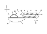
- the endless conveyor 11 of the continuous coagulator 10 is configured such that the tips or mounting ends of the plurality of partition blades 13 move horizontally in the feeding direction, as shown in FIG. As in the second modification, it may be configured to rise and move near the outlet of the coagulation tank 20. That is, the conveyor belt (endless chain) 12 of the endless conveyor 11 is inclined upward by an angle ⁇ 0 toward the feeding direction of the continuous coagulator 10 so that the tip or the mounting end of the partition blade 13 gradually rises upward. (Range of 0 ° ⁇ ⁇ 0 ⁇ 30 °).
- the roller 14 on the outlet side is arranged higher than the roller 15 on the inlet side, and the conveyor belt (endless chain) 12 rises together with the partition blade 13 after passing through the guide roller 25, and the partition blade 13 is used as a lower cloth. It is configured to gradually move away from 42.
- the endless conveyor 11 may be configured so that the inclination of the conveyor belt (endless chain) 12 can be arbitrarily adjusted.
- the continuous coagulator 10 is provided with a supply port 24 for supplying soymilk containing a coagulant on the side wall 22 of the coagulation tank 20 near the inlet of the coagulation tank 20, but the third is shown in FIG.
- the supply port 24 may be provided on the bottom wall 21 of the coagulation tank 20.
- the liquid level is set assuming the case of tofu having the smallest amount of coagulated soymilk supplied into the coagulation compartment.
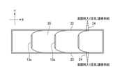
- soymilk and a coagulant are poured from above the inlet side of the coagulant 10, the supply port 24 is installed at a certain distance so as not to interfere with the orbiting partition blade 13, so that the coagulant is foamed or inflows. Bubbles were mixed and the coagulation tended to be non-uniform. In addition, the space of the solidification section was not stable and uneven solidification was likely to occur. In particular, soymilk, which is a non-foaming agent, is very easy to foam, and significant air bubbles are mixed.
- the shape of the space of the coagulation section is fixed (rectangular parallelepiped shape), and when the soymilk containing the coagulant is poured from the supply port 24, it is mostly near the liquid surface or in the liquid. Since it is poured into the soymilk, a homogeneous pudding-like soymilk coagulate with less foaming and less air bubbles can be stably obtained. Since the shape of the solidification section changes at the position where the partition plate turns from the return side to the feed side, the coagulant is formed when the solidification section is separated by the front and rear partition plates after the turning position and then fixed without change. It is possible to stably obtain a coagulated state with high water retention by adding soymilk containing soymilk.
- the supply port 24 is not limited to one side wall of the present embodiment or one bottom wall of the third modification, but two supply ports on both side walls, a plurality of places on the bottom wall, and both side walls and the bottom wall. It may be appropriately designed, such as the three locations of.
- the continuous coagulator 10 supplies steam above the cover 29 to the cleaning unit 26 for cleaning the partition blade 13 located at the return portion and the inside of the cover 29.
- a steam supply device 27 may be further provided.
- a saucer 28 for receiving the cleaning liquid may be provided below the partition blade 13 and the conveyor belt (endless chain) 12 located at the return portion below the cleaning portion 26. It can be washed easily and can maintain a hygienic environment even during long-term production.
- the supply port 24 may be a discharge port for discharging soymilk containing a coagulant or a cleaning chemical solution, or a discharge port may be separately provided near the inlet of the coagulation tank 20.
- the soymilk coagulated product By supplying steam into the cover 29 by the steam supply device 27, the soymilk coagulated product can be kept at a predetermined temperature.
- the space inside the cover 29 with saturated steam at 60 to 100 ° C. together with the steam generated from the soymilk coagulum, it is possible to prevent the growth of germs and hygienically transport the soymilk coagulation.
- the cleaning unit 26 can perform CIP (Cleaning in place) cleaning with a chemical solution and sterilization with steam, hot water, or a chemical solution. Since the partition blade 13 orbits the boat-shaped continuous coagulator 10, it is unsanitary if the tofu residue adhering to the partition blade 13 (a part made of stainless steel or rubber spatula) passes for a long time. Therefore, the partition blade 13 orbits during production.
- a cleaning section 26 equipped with a high-pressure cleaning nozzle is provided at the return portion of the track to wash off the tofu residue.
- the cleaning chemical solution is deeply stored in the coagulation tank 20 (preferably full liquid above the level of soymilk coagulant at the time of production), and the dipping cleaning in which the partition blade 13 is rotated is also used.
- the cleaning chemicals discharged from the outlet end 21a of the coagulation tank 20 are returned to the soymilk tank or the cleaning chemicals tank after removing solids with a filter. Rinse drainage is not returned, but drained.
- a spray nozzle rotary spray nozzle, spray ball, etc. capable of spraying the chemical solution may be provided in the cover 29, and the inside of the cover 29, the coagulation tank 20, and the partition blade 13 may be CIP-cleaned.
- the coagulation tank 20 may be provided with a double structure or a heat insulating means.
- the coagulation tank 20 is generally made of stainless steel, but in the one-sheet structure, heat dissipation is large and the quality of tofu near the side wall and the bottom wall becomes soft. It may cause trouble with cloth in the later molding machine 30.
- a heat insulating means such as providing an air layer with a double structure, putting a heat insulating material, making a vacuum layer, and controlling the circulation temperature of hot water or steam or a heat medium, the tofu after aging can be kept near the side wall.
- the quality of the tofu in the center is the same, and the tofu that has good adhesion, elasticity, and soft pudding is produced, and the loss is reduced.
- the amount of tofu lees adhering to the partition blade 13 can be reduced. It also saves money by not using extra coagulant or washing water.
- the partition blade 13 may be attached to the surface of the conveyor belt (endless chain) 12 in the range of 45 ° ⁇ ⁇ ⁇ 150 °, preferably 60 ° ⁇ ⁇ ⁇ 90 °.
- 45 ° ⁇ ⁇ ⁇ 90 ° or 60 ° ⁇ ⁇ ⁇ 90 so that the tip of the partition blade 13 is closer to the inlet with respect to the base end in the feed portion. It may be mounted at an angle of °, which can reduce the kicking up of the upper part of the soymilk coagulum near the outlet.
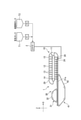
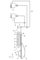
- soymilk and the coagulant are sent from the soymilk tank T1 and the coagulant tank T2 at a predetermined flow rate by the metering pumps P1 and P2, and the coagulant is mixed by the mixer 2.
- soymilk is supplied to the coagulation tank 20
- valves V1 and V2 are provided between the metering pumps P1 and P2 and the mixer 2
- soymilk is returned to the soymilk tank T1 and the coagulant is returned to the coagulant tank T2.
- C1 and C2 are provided.
- the soymilk containing the coagulant may be continuously supplied, or it may be supplied continuously. It may be a batch type supply.
- soymilk and coagulant switching valves V1 and V2 are switched to the production side, and each of them is constantly flowed at a predetermined flow rate, and the partition blade 13 of the coagulant tank 20 is continuously driven. do. In this case, the partition blade 13 cannot be driven in a batch manner.
- the switching valves V1 and V2 of the soymilk and the coagulant are switched from the circulation side to the production side, and the coagulant is mixed by the mixer 2.
- the supply of soymilk containing the agent to the coagulation tank 20 is started.
- the switching valves V1 and V2 are switched to the circulation side to stop the supply.
- the partition blade 13 may be continuously driven, or the partition blade 13 may be driven in batch after the supply is stopped, and the next partition blade 13 comes to a predetermined position. Therefore, the partition blade 13 is preferably driven by a basic continuous drive, but may be driven by a batch type.
- End cutting means that when the soymilk switching valve V1 and the coagulant switching valve V2 are switched from the production side to the circulation side, the valve V2 is switched more quickly, and the valves V1 to the mixer 2 to the supply port 24 are filled with only soymilk. To wait. As a result, the soymilk coagulant is prevented from being clogged in the front and back of the mixer 2 and the mixer 2, and the tofu whose coagulation is broken is prevented from being mixed and the quality is deteriorated.
- the soymilk content is supplied in the next batch, but it mixes with the soymilk containing a coagulant and there is no quality problem. Making a part where the coagulant is not put in for the last short time and delaying the timing of the valve V1 in this way is called “edge cutting".
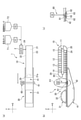
- a pair of endless chains 71, 71 connecting the conveyor belts 12 on both sides in the width direction thereof is a sprocket 70. , 70.
- the sprocket 70, 70 rotates the drive shaft 75 by the drive unit 74, so that the conveyor belt 12 is driven together with the endless chains 71, 71.
- the conveyor belt 12 is composed of a plurality of metal plates connected to endless chains 71, 71, and partition blades 13 are attached to the surface of these metal plates.
- the metal plate may be not only a flat plate shape but also an angle shape or a round bar shape, and H-shaped steel, C-shaped steel, or the like may be applied.
- the material of the metal plate is not limited to stainless steel, and may be titanium, aluminum, or hard resin.
- the endless conveyor 11 may have no conveyor belt 12 and the partition blades 13 may be directly attached to the endless chain 71. Further, a sprocket on the driven side is arranged at the position of the roller 15 in FIG. 1 (not shown).
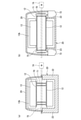
- the endless chains 71, 71 and the sprockets 70, 70 are arranged inside the side walls 22 and 23 of the coagulation tank 20 in the width direction, whereas in the example of FIG. 8 (b). , Is arranged on the outer side in the width direction of the side walls 22 and 23 of the coagulation tank 20.
- the continuous coagulator 10 can be designed compactly in the width direction, and at the time of cleaning, the conveyor belt 12, the endless chain 71, The 71 and the sprockets 70, 70 can be cleaned together with the partition blade 13.
- the endless chains 71 and 71 are not particularly limited, but it is preferable to use a chain such as an ultra-long-life non-lubricated stainless steel chain in which foreign matter is unlikely to be generated.
- a chain such as an ultra-long-life non-lubricated stainless steel chain in which foreign matter is unlikely to be generated.
- An example is a SUS-RB ultra-long-life stainless steel chain made of an RB ceramic (porous carbon material) composite material and SUS304, and even when used oil-free, wear elongation can be significantly suppressed.
- Other examples of the endless chains 71 and 71 include bearing roller conveyor chains with oil-free and water-resistant specifications, environment-resistant conveyor chains, and stainless steel conveyor chains with excellent corrosion resistance, chemical resistance, heat resistance, and cold resistance. Be done.
- the endless conveyor 11 may have a configuration having three sets of endless chains and sprockets by connecting the endless chain to the central portion in the width direction of the conveyor belt 12.
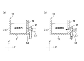
- the continuous coagulant has a supply port 24 for supplying soymilk containing a coagulant from the side wall 22 of the coagulation tank 20 in the vicinity of the inlet of the coagulation tank 20, but in the second embodiment.
- the coagulation tank 20 has an opening / closing member that opens and closes the supply port 24 to prevent liquid leakage and backflow from the supply port 24.
- a shutter-type lid 50 that can be opened and closed by a cylinder 53 is provided on the side wall 22 having the supply port 24.
- the shutter-type lid 50 is closed while the partition blade 13 passes through the supply port 24.
- the rear partition blade 13 comes to the lowermost end, and there is no leakage of soymilk coagulant between the side walls 22 and 23 and the inner surface of the bottom wall 21. From the state where the sealing property is firmly secured, the shutter-type lid 50 is opened, and soymilk containing a coagulant is weighed and poured into the coagulation section of the coagulation tank 20 almost under the liquid level for a predetermined time.
- the shutter-type lid 50 When the weighing is completed, the shutter-type lid 50 is closed. That is, the partition blade 13 may be driven continuously or in batch, but the soymilk containing the coagulant is supplied in batch. Further, the shutter-type lid 50 may be opened to supply soymilk containing a coagulant at least until the partition blade 13 overlaps the supply port 24 again.
- the semi-ripened or uncoagulated soymilk coagulant containing a coagulant leaks backward before and after the partition blades 13 that orbit continuously overlap. Therefore, as in the first modification shown in FIG. 11, it is preferable to use a shutter-type lid 51 that can be opened and closed up and down without a step between the inner surface of the side wall 22 and the lid surface in the closed state. Further, as in the second modification shown in FIG. 12, even in a form in which a commercially available sanitary tank valve (tank bottom valve) 52 is used and the tip portion of the valve 52 closes the inner surface of the side wall 22 without a step in the closed state. good.
- soymilk containing a coagulant is supplied in accordance with the opening and closing of the opening / closing members (shutter type lid 51, tank valve 52) at the timing when the partition blade 13 and the supply port 24 overlap. Will be intermittent (batch type supply).
- the opening / closing member when the opening / closing member is not provided in the supply port 24 as in the above embodiment, it is preferable to provide the supply port 24 above the liquid level of the soymilk containing the coagulant to be supplied to the coagulation section.
- the supply of soymilk containing a coagulant may be continuous.
- the liquid level is not so high and the moving speed of the partition blade 13 is not so slow (passing through the supply port 24). In this case, the moving speed may be increased for a moment.) Since the amount of leakage is small and there is no problem, in this case as well, the opening / closing member itself may not be provided.
- the rubber scraper 13a is formed long in the width direction, and the side wall 22 ,.
- the supply port 24 of 23 is temporarily closed.
- the rubber scraper 13a can also be applied when the supply port 24 is provided only on one side wall.
- the fourth modification shown in FIG. 14 when the supply port 24 is formed on the bottom wall 21 of the coagulation tank 20, the rubber scraper 13b is formed long in the vertical direction, and the supply port 24 of the bottom wall 21 is formed. I try to temporarily block it. In the case of the third and fourth modifications, soymilk containing a coagulant may be continuously supplied.
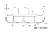
- two supply ports 24a and 24b are provided at positions close to one side wall 22 of the coagulation tank 20, soymilk containing a coagulant is continuously supplied, and a three-way valve 56 is used.
- the supply port is switched to supply to the continuous coagulator.
- the supply direction is changed by the three-way valve 56, the supply from the supply port 24b is not performed, and the supply from the supply port 24a is continued.
- the soymilk containing the coagulant is continuously supplied, and the partition blade 13 is also continuously driven.
- each supply port is provided with an opening / closing member such as a tank valve.
- the soymilk containing the coagulant is supplied to the compartment A by the flow path on the right side, while the flow path on the left side overlaps with the partition blade 13 and is closed.
- the three-way valve 56 is switched and soymilk containing a coagulant is supplied to the section B through the flow path on the right side. After that, the soymilk containing the coagulant is continuously supplied by repeating this process. Therefore, unlike batch-type solidification, edge cutting is not required, uneven solidification is reduced, and more uniform solidification quality is obtained.
- a switching valve may be provided according to the number of supply ports 24.
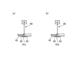
- the upper surface of the protective plate 61 can be firmly broken down to the bottom of the soymilk coagulant, the water can be separated from the lower cloth 42, and the drainage can be improved. Furthermore, it is possible to obtain tofu that is hard and has uniform hardness. Therefore, in the past, in order to protect the lower cloth 42, it was broken at a height of 5 to 10 mm above the lower cloth 42, so that the bottom surface hardly collapses and the problem of becoming "two-layer tofu" is solved. Can be done.
- the upper surface of the protective plate 61 is arranged so as to be flush with the portion of the lower cloth 42 on the upstream side and the downstream side with respect to the position below the breaking device 60, so that the soymilk coagulated product can be smoothly conveyed. can.
- the protective plate 61 to which the breaking device 60 can come into contact may also have the function of the guide roll 63, and specifically, protects the protective plate 61.
- the plates 61a and 61b have a thickness that does not damage the lower cloth 42, and are chamfered with rounded corners.
- the protective plate 61a of FIG. 17A has an elliptical shape in which both the upper surface side and the lower surface side are curved, and the protective plate 61b of FIG. 17B has a flat upper surface side and a curved lower surface side. ing.
- the protective plate 61 may be made of a rigid metal such as stainless steel, or may be made of a resin or rubber and made of an elastic material.
- the pudding-like and soft soymilk coagulant can be made into silken tofu or soybean flower (tofu flower) without pressing it as it is. Further, the pudding-like coagulated soymilk can be lightly pressed and only the texture is applied to make soft tofu.
- the pudding-like coagulated soymilk is appropriately crushed to a desired degree by the crushing device 60 and pressed to produce cotton tofu, fried tofu / fried tofu, hard tofu, and tofu.
- Fried tofu, hard tofu, and shimadofu are generally produced from rag-like coagulant, but it can also be produced by finely breaking the pudding-like coagulant obtained from thin soymilk. It becomes a tofu that retains water and does not easily lose its taste, and it becomes easier to maintain a delicious state even if it is stored for a long time such as boil sterilization.
- the continuous coagulator 10 produces soymilk having a solid content of 3 to 20% wt, preferably 5 to 15% wt at 50 to 95 ° C (preferably 60 to 85 ° C).
- soymilk having a solid content of 3 to 20% wt, preferably 5 to 15% wt at 50 to 95 ° C (preferably 60 to 85 ° C).
- the coagulated product may be separated from the "yu", which is a so-called “rag-like” coagulation state. You can expect it.
- a slow-acting coagulant in which the time from mixing with soymilk to the start of coagulation is 5 to 180 seconds, preferably 10 to 120 seconds, and emulsified bittern can also be preferably used.
- a commercially available slow-acting coagulant may be used, and in addition to emulsified bittern in which magnesium chloride is wrapped in oil or an emulsifier, for example, GDL (glucono delta lactone), sushi powder (calcium sulfate, coarse granules), salt.
- GDL glucono delta lactone
- sushi powder calcium sulfate, coarse granules
- salt for example, GDL (glucono delta lactone), sushi powder (calcium sulfate, coarse granules), salt.
- Use slow-acting coagulants such as transglutaminase.
- a gelling auxiliary material such as agar, carrageenan, curdlan, and starch. Further, a manufacturing method in which these are appropriately blended may be used. When emulsified bittern is used as the coagulant, the sweetness can also be increased.
- a pH adjuster such as baking soda
- a polyphosphoric acid-based additive having a chelating action may be used in combination with soymilk.
Landscapes
- Engineering & Computer Science (AREA)
- Life Sciences & Earth Sciences (AREA)
- Chemical & Material Sciences (AREA)
- Food Science & Technology (AREA)
- Polymers & Plastics (AREA)
- Mechanical Engineering (AREA)
- Agronomy & Crop Science (AREA)
- Botany (AREA)
- Health & Medical Sciences (AREA)
- Nutrition Science (AREA)
- Manufacturing & Machinery (AREA)
- Beans For Foods Or Fodder (AREA)
Priority Applications (4)
| Application Number | Priority Date | Filing Date | Title |
|---|---|---|---|
| US17/906,740 US20230137565A1 (en) | 2020-07-13 | 2021-07-09 | Soybean curd production device and soybean curd production method |
| KR1020227034210A KR20230036058A (ko) | 2020-07-13 | 2021-07-09 | 두부류 제조 장치 및 두부류 제조 방법 |
| JP2022536322A JPWO2022014491A1 (enExample) | 2020-07-13 | 2021-07-09 | |
| CN202180021434.8A CN115279203A (zh) | 2020-07-13 | 2021-07-09 | 豆腐制造装置及豆腐制造方法 |
Applications Claiming Priority (2)
| Application Number | Priority Date | Filing Date | Title |
|---|---|---|---|
| JP2020-119817 | 2020-07-13 | ||
| JP2020119817 | 2020-07-13 |
Publications (1)
| Publication Number | Publication Date |
|---|---|
| WO2022014491A1 true WO2022014491A1 (ja) | 2022-01-20 |
Family
ID=79555496
Family Applications (1)
| Application Number | Title | Priority Date | Filing Date |
|---|---|---|---|
| PCT/JP2021/025947 Ceased WO2022014491A1 (ja) | 2020-07-13 | 2021-07-09 | 豆腐類製造装置及び豆腐類製造方法 |
Country Status (5)
| Country | Link |
|---|---|
| US (1) | US20230137565A1 (enExample) |
| JP (1) | JPWO2022014491A1 (enExample) |
| KR (1) | KR20230036058A (enExample) |
| CN (1) | CN115279203A (enExample) |
| WO (1) | WO2022014491A1 (enExample) |
Cited By (2)
| Publication number | Priority date | Publication date | Assignee | Title |
|---|---|---|---|---|
| KR20230117029A (ko) * | 2022-01-29 | 2023-08-07 | 서신식품 주식회사 | 순두부 파쇄 시스템 |
| CN119079399A (zh) * | 2024-10-08 | 2024-12-06 | 潜江市昌贵水产食品股份有限公司 | 一种小龙虾计量输送机构、油炸生产线及其应用方法 |
Citations (8)
| Publication number | Priority date | Publication date | Assignee | Title |
|---|---|---|---|---|
| JPS5012282A (enExample) * | 1973-06-06 | 1975-02-07 | ||
| JPS5551536B2 (enExample) * | 1972-02-17 | 1980-12-24 | ||
| JPH01320965A (ja) * | 1988-06-21 | 1989-12-27 | Masamori Osada | 豆腐の自動製造方法及びその装置 |
| JPH02273151A (ja) * | 1989-04-14 | 1990-11-07 | Sanyo Shokuhin Kk | 豆腐の自動連続製造装置 |
| JPH0376554A (ja) * | 1989-08-17 | 1991-04-02 | Sanyo Shokuhin Kk | 豆腐の自動連続製造装置 |
| JPH0391453A (ja) * | 1989-09-01 | 1991-04-17 | Sanyo Shokuhin Kk | 自動豆腐製造装置の清浄方法 |
| JPH06276981A (ja) * | 1993-03-25 | 1994-10-04 | Sooee Mach:Kk | 豆腐の連続凝固装置 |
| JPH0928341A (ja) * | 1995-07-25 | 1997-02-04 | Yanagiya:Kk | 豆腐の製造方法及び豆腐製造装置並びに豆腐の連続製造装置 |
Family Cites Families (3)
| Publication number | Priority date | Publication date | Assignee | Title |
|---|---|---|---|---|
| JPS535736B2 (enExample) | 1972-02-17 | 1978-03-01 | ||
| JPS5227232B2 (enExample) | 1974-12-13 | 1977-07-19 | ||
| JPS5339507B2 (enExample) | 1975-03-12 | 1978-10-21 |
-
2021
- 2021-07-09 CN CN202180021434.8A patent/CN115279203A/zh active Pending
- 2021-07-09 KR KR1020227034210A patent/KR20230036058A/ko not_active Withdrawn
- 2021-07-09 US US17/906,740 patent/US20230137565A1/en not_active Abandoned
- 2021-07-09 WO PCT/JP2021/025947 patent/WO2022014491A1/ja not_active Ceased
- 2021-07-09 JP JP2022536322A patent/JPWO2022014491A1/ja active Pending
Patent Citations (8)
| Publication number | Priority date | Publication date | Assignee | Title |
|---|---|---|---|---|
| JPS5551536B2 (enExample) * | 1972-02-17 | 1980-12-24 | ||
| JPS5012282A (enExample) * | 1973-06-06 | 1975-02-07 | ||
| JPH01320965A (ja) * | 1988-06-21 | 1989-12-27 | Masamori Osada | 豆腐の自動製造方法及びその装置 |
| JPH02273151A (ja) * | 1989-04-14 | 1990-11-07 | Sanyo Shokuhin Kk | 豆腐の自動連続製造装置 |
| JPH0376554A (ja) * | 1989-08-17 | 1991-04-02 | Sanyo Shokuhin Kk | 豆腐の自動連続製造装置 |
| JPH0391453A (ja) * | 1989-09-01 | 1991-04-17 | Sanyo Shokuhin Kk | 自動豆腐製造装置の清浄方法 |
| JPH06276981A (ja) * | 1993-03-25 | 1994-10-04 | Sooee Mach:Kk | 豆腐の連続凝固装置 |
| JPH0928341A (ja) * | 1995-07-25 | 1997-02-04 | Yanagiya:Kk | 豆腐の製造方法及び豆腐製造装置並びに豆腐の連続製造装置 |
Cited By (3)
| Publication number | Priority date | Publication date | Assignee | Title |
|---|---|---|---|---|
| KR20230117029A (ko) * | 2022-01-29 | 2023-08-07 | 서신식품 주식회사 | 순두부 파쇄 시스템 |
| KR102623487B1 (ko) | 2022-01-29 | 2024-01-10 | 서신식품 주식회사 | 순두부 파쇄 시스템 |
| CN119079399A (zh) * | 2024-10-08 | 2024-12-06 | 潜江市昌贵水产食品股份有限公司 | 一种小龙虾计量输送机构、油炸生产线及其应用方法 |
Also Published As
| Publication number | Publication date |
|---|---|
| CN115279203A (zh) | 2022-11-01 |
| JPWO2022014491A1 (enExample) | 2022-01-20 |
| KR20230036058A (ko) | 2023-03-14 |
| US20230137565A1 (en) | 2023-05-04 |
Similar Documents
| Publication | Publication Date | Title |
|---|---|---|
| WO2022014491A1 (ja) | 豆腐類製造装置及び豆腐類製造方法 | |
| WO2017056280A1 (ja) | 豆腐類の連続成型装置 | |
| US20100275790A1 (en) | Continuous curding machine for tofu products | |
| JP2010227092A (ja) | 豆腐・油揚げ生地の脱水・成型方法とその装置 | |
| JP2018102264A (ja) | 豆腐類連続製造装置および製造方法 | |
| WO2021225128A1 (ja) | 豆腐の移送機構及び豆腐の連続製造装置 | |
| CN105558803A (zh) | 生鲜面的制造设备、制造方法及控制系统 | |
| JP2013244121A (ja) | 茹で器の給排水装置 | |
| JPWO2022014491A5 (enExample) | ||
| CN217407602U (zh) | 一种甜品的酱料层涂覆设备 | |
| CN209268675U (zh) | 一种荔枝清洗杀菌设备 | |
| US20230320393A1 (en) | Method and device for manufacturing tofu products | |
| CN218464486U (zh) | 一种粉剂线的混合物料缓冲罐 | |
| WO2022270473A1 (ja) | 豆腐類製造装置 | |
| JP2023001853A (ja) | 豆腐類製造装置 | |
| JP3436927B2 (ja) | 豆乳のインライン凝固装置 | |
| CN219781393U (zh) | 一种带有清洗装置的蛋糕充气系统 | |
| CN118926187A (zh) | 一种用于肉类产品中塑料颗粒去除的超声波清洗机 | |
| AU2005202561B2 (en) | Apparatus for preparing curd and for feeding the prepared curd to a curd processing apparatus | |
| CA2229356C (en) | Continuous cheese coagulation method | |
| CN117137063A (zh) | 一种食品熟化加热灭菌设备 | |
| CN120094292A (zh) | 一种利用乳品深加工制取酪蛋白的装置 | |
| JPH01320965A (ja) | 豆腐の自動製造方法及びその装置 | |
| CN207784200U (zh) | 一种凉糕生产系统 | |
| CN104286200A (zh) | 生产水豆腐的仿手工冲浆系统 |
Legal Events
| Date | Code | Title | Description |
|---|---|---|---|
| 121 | Ep: the epo has been informed by wipo that ep was designated in this application |
Ref document number: 21841729 Country of ref document: EP Kind code of ref document: A1 |
|
| ENP | Entry into the national phase |
Ref document number: 2022536322 Country of ref document: JP Kind code of ref document: A |
|
| NENP | Non-entry into the national phase |
Ref country code: DE |
|
| 122 | Ep: pct application non-entry in european phase |
Ref document number: 21841729 Country of ref document: EP Kind code of ref document: A1 |