WO2022014491A1 - Soybean curd production device and soybean curd production method - Google Patents
Soybean curd production device and soybean curd production method Download PDFInfo
- Publication number
- WO2022014491A1 WO2022014491A1 PCT/JP2021/025947 JP2021025947W WO2022014491A1 WO 2022014491 A1 WO2022014491 A1 WO 2022014491A1 JP 2021025947 W JP2021025947 W JP 2021025947W WO 2022014491 A1 WO2022014491 A1 WO 2022014491A1
- Authority
- WO
- WIPO (PCT)
- Prior art keywords
- coagulant
- coagulation tank
- tofu
- soymilk
- continuous
- Prior art date
Links
Images


Classifications
-
- A—HUMAN NECESSITIES
- A23—FOODS OR FOODSTUFFS; TREATMENT THEREOF, NOT COVERED BY OTHER CLASSES
- A23P—SHAPING OR WORKING OF FOODSTUFFS, NOT FULLY COVERED BY A SINGLE OTHER SUBCLASS
- A23P30/00—Shaping or working of foodstuffs characterised by the process or apparatus
- A23P30/10—Moulding
-
- A—HUMAN NECESSITIES
- A23—FOODS OR FOODSTUFFS; TREATMENT THEREOF, NOT COVERED BY OTHER CLASSES
- A23L—FOODS, FOODSTUFFS, OR NON-ALCOHOLIC BEVERAGES, NOT COVERED BY SUBCLASSES A21D OR A23B-A23J; THEIR PREPARATION OR TREATMENT, e.g. COOKING, MODIFICATION OF NUTRITIVE QUALITIES, PHYSICAL TREATMENT; PRESERVATION OF FOODS OR FOODSTUFFS, IN GENERAL
- A23L11/00—Pulses, i.e. fruits of leguminous plants, for production of food; Products from legumes; Preparation or treatment thereof
- A23L11/40—Pulse curds
- A23L11/45—Soy bean curds, e.g. tofu
-
- A—HUMAN NECESSITIES
- A23—FOODS OR FOODSTUFFS; TREATMENT THEREOF, NOT COVERED BY OTHER CLASSES
- A23P—SHAPING OR WORKING OF FOODSTUFFS, NOT FULLY COVERED BY A SINGLE OTHER SUBCLASS
- A23P30/00—Shaping or working of foodstuffs characterised by the process or apparatus
-
- B—PERFORMING OPERATIONS; TRANSPORTING
- B65—CONVEYING; PACKING; STORING; HANDLING THIN OR FILAMENTARY MATERIAL
- B65G—TRANSPORT OR STORAGE DEVICES, e.g. CONVEYORS FOR LOADING OR TIPPING, SHOP CONVEYOR SYSTEMS OR PNEUMATIC TUBE CONVEYORS
- B65G15/00—Conveyors having endless load-conveying surfaces, i.e. belts and like continuous members, to which tractive effort is transmitted by means other than endless driving elements of similar configuration
- B65G15/10—Conveyors having endless load-conveying surfaces, i.e. belts and like continuous members, to which tractive effort is transmitted by means other than endless driving elements of similar configuration comprising two or more co-operating endless surfaces with parallel longitudinal axes, or a multiplicity of parallel elements, e.g. ropes defining an endless surface
- B65G15/12—Conveyors having endless load-conveying surfaces, i.e. belts and like continuous members, to which tractive effort is transmitted by means other than endless driving elements of similar configuration comprising two or more co-operating endless surfaces with parallel longitudinal axes, or a multiplicity of parallel elements, e.g. ropes defining an endless surface with two or more endless belts
- B65G15/14—Conveyors having endless load-conveying surfaces, i.e. belts and like continuous members, to which tractive effort is transmitted by means other than endless driving elements of similar configuration comprising two or more co-operating endless surfaces with parallel longitudinal axes, or a multiplicity of parallel elements, e.g. ropes defining an endless surface with two or more endless belts the load being conveyed between the belts
-
- B—PERFORMING OPERATIONS; TRANSPORTING
- B65—CONVEYING; PACKING; STORING; HANDLING THIN OR FILAMENTARY MATERIAL
- B65G—TRANSPORT OR STORAGE DEVICES, e.g. CONVEYORS FOR LOADING OR TIPPING, SHOP CONVEYOR SYSTEMS OR PNEUMATIC TUBE CONVEYORS
- B65G15/00—Conveyors having endless load-conveying surfaces, i.e. belts and like continuous members, to which tractive effort is transmitted by means other than endless driving elements of similar configuration
- B65G15/30—Belts or like endless load-carriers
- B65G15/32—Belts or like endless load-carriers made of rubber or plastics
- B65G15/42—Belts or like endless load-carriers made of rubber or plastics having ribs, ridges, or other surface projections
-
- B—PERFORMING OPERATIONS; TRANSPORTING
- B65—CONVEYING; PACKING; STORING; HANDLING THIN OR FILAMENTARY MATERIAL
- B65G—TRANSPORT OR STORAGE DEVICES, e.g. CONVEYORS FOR LOADING OR TIPPING, SHOP CONVEYOR SYSTEMS OR PNEUMATIC TUBE CONVEYORS
- B65G19/00—Conveyors comprising an impeller or a series of impellers carried by an endless traction element and arranged to move articles or materials over a supporting surface or underlying material, e.g. endless scraper conveyors
- B65G19/02—Conveyors comprising an impeller or a series of impellers carried by an endless traction element and arranged to move articles or materials over a supporting surface or underlying material, e.g. endless scraper conveyors for articles, e.g. for containers
-
- B—PERFORMING OPERATIONS; TRANSPORTING
- B65—CONVEYING; PACKING; STORING; HANDLING THIN OR FILAMENTARY MATERIAL
- B65G—TRANSPORT OR STORAGE DEVICES, e.g. CONVEYORS FOR LOADING OR TIPPING, SHOP CONVEYOR SYSTEMS OR PNEUMATIC TUBE CONVEYORS
- B65G19/00—Conveyors comprising an impeller or a series of impellers carried by an endless traction element and arranged to move articles or materials over a supporting surface or underlying material, e.g. endless scraper conveyors
- B65G19/04—Conveyors comprising an impeller or a series of impellers carried by an endless traction element and arranged to move articles or materials over a supporting surface or underlying material, e.g. endless scraper conveyors for moving bulk material in open troughs or channels
- B65G19/06—Conveyors comprising an impeller or a series of impellers carried by an endless traction element and arranged to move articles or materials over a supporting surface or underlying material, e.g. endless scraper conveyors for moving bulk material in open troughs or channels the impellers being scrapers similar in size and shape to the cross-section of the trough or channel
- B65G19/08—Conveyors comprising an impeller or a series of impellers carried by an endless traction element and arranged to move articles or materials over a supporting surface or underlying material, e.g. endless scraper conveyors for moving bulk material in open troughs or channels the impellers being scrapers similar in size and shape to the cross-section of the trough or channel and attached to a single belt, rope or chain
-
- B—PERFORMING OPERATIONS; TRANSPORTING
- B65—CONVEYING; PACKING; STORING; HANDLING THIN OR FILAMENTARY MATERIAL
- B65G—TRANSPORT OR STORAGE DEVICES, e.g. CONVEYORS FOR LOADING OR TIPPING, SHOP CONVEYOR SYSTEMS OR PNEUMATIC TUBE CONVEYORS
- B65G19/00—Conveyors comprising an impeller or a series of impellers carried by an endless traction element and arranged to move articles or materials over a supporting surface or underlying material, e.g. endless scraper conveyors
- B65G19/18—Details
- B65G19/22—Impellers, e.g. push-plates, scrapers; Guiding means therefor
-
- B—PERFORMING OPERATIONS; TRANSPORTING
- B65—CONVEYING; PACKING; STORING; HANDLING THIN OR FILAMENTARY MATERIAL
- B65G—TRANSPORT OR STORAGE DEVICES, e.g. CONVEYORS FOR LOADING OR TIPPING, SHOP CONVEYOR SYSTEMS OR PNEUMATIC TUBE CONVEYORS
- B65G2201/00—Indexing codes relating to handling devices, e.g. conveyors, characterised by the type of product or load being conveyed or handled
- B65G2201/02—Articles
- B65G2201/0202—Agricultural and processed food products
-
- B—PERFORMING OPERATIONS; TRANSPORTING
- B65—CONVEYING; PACKING; STORING; HANDLING THIN OR FILAMENTARY MATERIAL
- B65G—TRANSPORT OR STORAGE DEVICES, e.g. CONVEYORS FOR LOADING OR TIPPING, SHOP CONVEYOR SYSTEMS OR PNEUMATIC TUBE CONVEYORS
- B65G2812/00—Indexing codes relating to the kind or type of conveyors
- B65G2812/01—Conveyors composed of several types of conveyors
- B65G2812/016—Conveyors composed of several types of conveyors for conveying material by co-operating units in tandem
- B65G2812/018—Conveyors composed of several types of conveyors for conveying material by co-operating units in tandem between conveyor sections
Definitions
- the present invention relates to a tofu manufacturing apparatus and a tofu manufacturing method having a continuous coagulator and a continuous molding machine.
- Patent Documents 1 to 4 describe that the tofu seeds obtained by coagulating soymilk are sent to the automatic molding section via the charging port in the automatic coagulation section.
- Patent Document 1 extreme crushing of tofu does not give a good quality product, and tofu seeds are not crushed as much as possible to make a thick and long tofu. It is stated that the amount of tofu seeds is quantified with a balanced weighted damper at the inlet.
- Patent Documents 1 and 2 since the automatic solidifying portion has a two-story structure arranged above the upper caterpillar of the automatic molding portion, the difference between the automatic solidifying portion and the automatic molding portion is considerable. The tofu crumbles not a little. In addition, when tofu is fed with a damper, the input port opens wide when a large amount of tofu is dropped, and the input port closes when a small amount of tofu is dropped, even though it has the effect of alleviating fluctuations in the input amount, especially soybean quality. If there is a change in the firmness of tofu due to changes, it is poorly quantitative.
- the present invention has been made in view of the above-mentioned problems, and can be supplied from a continuous coagulant onto the lower cloth of a continuous molding machine without breaking the soymilk coagulant while ensuring quantitativeness.
- the present invention is to provide a tofu manufacturing apparatus and a tofu manufacturing method.
- a boat-shaped continuous coagulator having an endless conveyor in which a plurality of partition blades are attached to the surface of a conveyor belt at predetermined intervals, and a coagulation tank having a concave cross section through which the partition blades pass inside.
- a continuous molding machine having at least a lower endless conveyor on which the lower cloth is wound and an upper endless conveyor on which the upper cloth is wound. It is a tofu manufacturing equipment with The lower endless conveyor overlaps the coagulation tank when viewed from above so that the lower cloth is located below the outlet end of the coagulation tank.
- the bottom wall of the coagulation tank is a tofu manufacturing apparatus formed substantially horizontally from the vicinity of the inlet of the coagulation tank toward the end of the coagulation tank.
- the tofu manufacturing apparatus according to (1) wherein the coagulation tank and the upper endless transport conveyor are arranged side by side in a straight line.
- the endless conveyor of the continuous coagulator inclines upward toward the feed direction of the continuous coagulator so that the tip or the mounting end of the partition blade rises near the outlet of the coagulation tank.
- the continuous coagulant puts soymilk, a coagulant, and soymilk containing a coagulant or a cleaning agent solution on at least one of the side walls and the bottom wall of the coagulant near the inlet of the coagulant.
- the tofu manufacturing apparatus according to any one of (1) to (3), which has a supply port for supplying or a discharge port for discharging them.
- the tofu manufacturing apparatus according to any one of (1) to (8), wherein the width of the coagulation tank is substantially equal to the width of the press portion of the continuous molding machine.
- a breaking device is provided between the coagulation tank and the upper endless transport conveyor above the lower cloth of the lower endless transport conveyor. At a position below the breaking device, a protective plate with which the breaking device can come into contact is arranged.
- the tofu manufacturing apparatus according to any one of (1) to (9), wherein the lower cloth of the lower endless transport conveyor is pushed down and guided so as to bypass the protective plate.
- the continuous coagulator further includes a cover that covers the upper part of the endless conveyor.
- any of (1) to (11), wherein the chain connecting the conveyor belt and the sprocket to which the chain is hung are arranged on the outer side in the width direction of the side wall of the solidification tank.
- the tofu manufacturing equipment described in Crab. (13) A tofu manufacturing method for producing tofu using the tofu manufacturing apparatus according to any one of (1) to (12).
- the continuous coagulator produces almost purine-like soymilk coagulant by coagulating and aging soymilk at 50 to 95 ° C. and a solid content of 3 to 20% wt with a coagulant.
- the continuous molding machine is a method for producing tofu, in which the soymilk coagulant is conveyed by the lower cloth and pressed as necessary to mold the tofu.
- the "almost purine-like soymilk coagulant” refers to a state of the coagulated product after coagulation and aging, in which the water separation is 20% or less, preferably 10% or less.
- the soymilk coagulated product can be supplied from the continuous coagulant onto the lower cloth of the continuous molding machine while ensuring the quantitativeness.
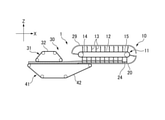
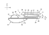
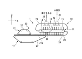
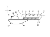
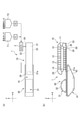
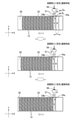
- (A) is a schematic top view showing a tofu manufacturing apparatus according to the first embodiment of the present invention
- (b) is a schematic side view of (a).
- FIG. 1 It is a schematic side view which shows the tofu manufacturing apparatus which concerns on 5th modification of 1st Embodiment of this invention. It is a schematic side view which shows the tofu manufacturing apparatus which concerns on the 6th modification of 1st Embodiment of this invention.
- (A) is a schematic side view corresponding to VIII-VIII of FIG. 1, showing a tofu manufacturing apparatus according to an example of a seventh modification of the first embodiment of the present invention, and (b) is the present invention.
- FIG. 1 It is a schematic side view corresponding to VIII-VIII of FIG. 1, which shows the tofu production apparatus which concerns on another example of 7th modification of 1st Embodiment of.
- FIG. 9 is a cross-sectional view of the vicinity of the inlet of the continuous coagulator of FIG. 9, where (a) shows a state in which the supply port is closed, and (b) shows a state in which the supply port is open. It is sectional drawing near the inlet of the continuous coagulant in the tofu manufacturing apparatus which concerns on 1st modification of 2nd Embodiment of this invention, (a) shows the state which the supply port is closed, (b). Indicates that the supply port is open.
- the feed portion of the coagulation tank of the continuous coagulator showing the process of supplying soymilk containing a coagulant to the continuous coagulant using a switching three-way valve.
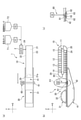
- A is a schematic top view showing a tofu manufacturing apparatus according to a third embodiment of the present invention
- (b) is a schematic side view of (a)
- (c) is (b). It is an enlarged view of the XV part.
- (A) is a figure corresponding to the XV part of FIG.
- the tofu manufacturing apparatus 1 of the first embodiment coagulates and matures soymilk containing a coagulant in which soymilk and a coagulant are mixed by a mixer 2 to produce a pudding-like soymilk coagulant.
- a boat-shaped continuous coagulator 10 and a continuous molding machine 30 for molding soymilk coagulant into tofu while dehydrating it are provided.
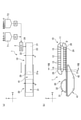
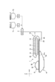
- the soymilk and the coagulant are sent from the stored soymilk tank T1 and the coagulant tank T2 at a predetermined flow rate by the metering pumps P1 and P2, mixed by the mixer 2, and sent to the continuous coagulant 10 as soymilk containing the coagulant. Will be supplied.
- the soymilk and the coagulant may be directly supplied separately to the continuous coagulant 10 and mixed in the coagulation tank 20. In any case, it is preferable that the majority (50% or more of the soymilk containing the coagulant in one section) is supplied below the liquid surface.
- the tofu manufacturing apparatus 1 of the present embodiment has a continuous coagulator 10 so that the continuous coagulant 10 feeds the soymilk containing the coagulant and the continuous molding machine 30 feeds the soymilk coagulant in the same direction.
- the continuous molding machine 30 and the continuous molding machine 30 are arranged side by side in a straight line. Although the installation space is widened, the soft, almost pudding-like coagulum can be transferred quantitatively without breaking it too much.
- the horizontal direction in which the continuous coagulator 10 and the continuous molding machine 30 are lined up is the X direction
- the width direction of the continuous coagulator 10 and the continuous molding machine 30, which is the horizontal direction orthogonal to the X direction is the Y direction, and is continuous.
- the vertical direction of the coagulator 10 and the continuous molding machine 30 is the Z direction.
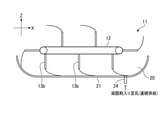
- the boat-shaped continuous coagulator 10 is made of an endless conveyor 11 on which a plurality of partition blades 13 are attached to the surface of a conveyor belt (endless chain) 12 at predetermined intervals, and a stainless steel having a concave cross section through which the partition blades 13 pass through. It mainly has a coagulation tank 20 and a cover 29 that covers the upper part of the endless conveyor 11.
- the conveyor belt (endless chain) 12 is hung around the two rollers 14 and 15 arranged substantially horizontally in the vicinity of the inlet and the outlet of the coagulation tank 20, and the two rollers 14 ,.
- the rotation of 15 orbits the conveyor belt (endless chain) 12 and the plurality of partition blades 13.
- the conveyor belt (endless chain) 12 of the continuous coagulator 10 is not particularly limited as long as it is a steel belt, a rigid metal belt such as stainless steel or titanium, a chain, or a wire and can fix a large number of partition blades.
- the plurality of partition blades 13 are composed of a metal steel plate member 13 such as stainless steel or titanium and a rubber member 13b, and have a rectangular shape that is long in the width direction and short in the vertical direction, and is a liquid such as soy milk or "yu".
- a rubber sealing member 13b such as flexible NBR, EPDM, FKM, etc. (fluororubber), silicon rubber, etc., inscribes or contacts the bottom wall 21 of the coagulation tank 20 and the inner surfaces of both side walls 22, 23 so as not to leak. Has a size. Therefore, the continuous coagulator 10 forms a coagulation section by the adjacent partition blades 13 and the coagulation tank 20.
- the bottom wall 21 of the coagulation tank 20 is curved in accordance with the trajectory of the tip of the partition blade 13 in the vicinity of the inlet for supplying soymilk containing a coagulant, while from the outlet end 21a to the curved portion toward the inlet. It is formed almost horizontally.
- At least one of the side walls 22 and 23 near the inlet of the coagulation tank 20 is provided with a supply port 24 for supplying soymilk containing a coagulant. Therefore, the soymilk containing the coagulant supplied from the supply port 24 is coagulated and aged by the partition blade 13 moving toward the outlet of the continuous coagulator 10.
- the supply port may be provided with an opening / closing member according to a second embodiment described later.
- the cover 29 is formed so as to cover the upper part of the entire plurality of partition blades 13 located at the return portion in accordance with the trajectory of the tip of the partition blade 13.
- the continuous molding machine 30 has an upper endless transfer conveyor 31 around which the upper cloth 32 is wound, and a lower endless transfer conveyor 41 around which the lower cloth 42 is wound.
- the surface of the upper cloth 32 facing downward and the surface of the lower cloth 42 facing upward are substantially horizontal and face each other with a gap.
- the central axes of the rollers of the upper endless conveyor 31 and the lower endless conveyor 41 are arranged parallel to the central axes of the two rollers 14 and 15 of the endless conveyor 11.
- the upper cloth 32 and the lower cloth 42 have flexibility and toughness, and are made of resin filter cloth (for example, patent No. 1) in which monofilaments such as fluororesin, polyester resin, polypropylene resin, and polyethylene resin are woven into plain weave or twill weave. (Refer to No. 400413, etc.), which is a flat-wound shape at the start and rear ends, and is a resin filter cloth belt that forms the bottom surface and side walls on the transport surface.
- a flat flex conveyor, chocolate conveyor, etc. may be used as long as it is a perforated or non-perforated food resin belt (Teflon belt or food belt).
- the upper endless transfer conveyor 31 and the lower endless transfer conveyor 41 sandwich the soymilk coagulant from above and below and press it to form tofu while dehydrating and transport it to the downstream process.
- the lower endless conveyor 41 overlaps the coagulation tank 20 when viewed from above so that the lower cloth 42 is located below the outlet end 21a of the bottom wall 21 of the coagulation tank 20. .. That is, the lower endless transfer conveyor 41 is configured to extend closer to the continuous coagulator side than the upper endless transfer conveyor 31 so as to be located close to the lower part of the coagulation tank 20.
- the coagulation tank 20 and the upper endless transfer conveyor 41 are arranged in a straight line in the X direction above the lower cloth 42 of the lower endless transfer conveyor 41.
- the continuous coagulator 10 is driven synchronously with the continuous molding machine 30. That is, the conveyor belt (endless chain) 12 of the endless conveyor 11 with the continuous coagulator 10, the upper cloth 32 of the endless transfer conveyor 31 on the upper side of the continuous molding machine 30, and the lower endless transfer conveyor 41.
- the cloth 42 is continuously driven in the same direction at the same speed at each feed portion.
- the head of the outlet end 21a of the bottom wall 21 of the coagulation tank 20 and the lower cloth 42 of the lower endless conveyor 41 are in a small state, and the soymilk coagulant does not go through the distributor or the input device.
- the inertial force of the pudding-like soymilk coagulant carried out from the continuous coagulator 10 can be directly transferred to the lower cloth 42. Further, the soymilk coagulated product can be transferred onto the lower cloth 42 while ensuring the quantitativeness by the coagulation section partitioned by the partition blade 13.
- the soymilk coagulant In the conventional two-story structure where the coagulant is placed above the molding machine, the soymilk coagulant is always in a crushed state due to the head, and tofu is produced in each partition division at the outlet of the coagulation tank. Since it flows out all at once, the endless conveyor of the coagulator is usually operated intermittently, and the molding machine is also operated intermittently accordingly. Further, when the coagulator and the molding machine were continuously operated, the soymilk coagulated product was likely to be incorporated unevenly.
- the tofu manufacturing apparatus 1 of the present embodiment has a one-story ground arrangement and is linear, the soymilk coagulant is suppressed from flowing out at once, and the soft pudding-like soymilk coagulant is not broken and remains as it is without a drop. Can be softly transferred onto the lower cloth 42.
- the tofu manufacturing apparatus 1 is maintained, the work at a high place is reduced and the work safety is improved.
- a coagulant using a steel belt (Patent No. 3568193) can be applied, but the breaking force is 60 gf / cm 2. less, specifically, 1 ⁇ 40gf / cm 2 or so, especially in the case of 5 ⁇ 20gf / cm 2 about very soft pudding-like soy milk coagulum, or slip, and cracked, transport well I can't.
- the continuous coagulator 10 of the present embodiment even the very soft pudding-like soymilk coagulated product having a small breaking force can be transported and transferred without being broken.
- the continuous coagulator 10 has a smaller head than the continuous molding machine 30 and is driven at the same speed at the same time, so that the extremely soft pudding-like soymilk coagulated product is not destroyed as it is, and is evenly under the continuous molding machine 30. It will be possible to transfer it on the cloth 42.
- the continuous coagulation machine 10 and the continuous molding machine 30 have less load on the machine and less starting current value of the drive motor than the intermittent operation (batch type), which saves energy.
- the effect of timing shift due to chain elongation due to long-term use is small.
- the width A of the coagulation tank 20 of the continuous coagulator 10 is substantially equal to the width B of the press portion (width in the Y direction of the upper cloth 32) of the continuous molding machine 30.
- the width A of the coagulation tank 20 is 80% to 100%, preferably 90% to 100%, with respect to the width B of the press portion.
- the width B of the press portion is 500 to 3,000 mm (generally 1,000 to 2,000 mm).
- the width of the coagulation tank of the boat-shaped coagulator is the molding width of the molding machine.
- the width A of the coagulation tank 20 of the continuous coagulator 10 is substantially equal to the width B of the press portion of the continuous molding machine 30, so that the soymilk coagulant is received by the continuous coagulator 10 and the continuous molding machine 30.
- the very soft, almost pudding-like coagulated soymilk that is carried out from the coagulator 10 is softened directly on the lower cloth 42 of the molding machine 30 without breaking it (without using a distributor or the like). You can land.
- the bottom wall 21 of the coagulation tank 20 is formed substantially horizontally from the vicinity of the inlet toward the outlet end 21a, there is no head and a little free water (so-called “yu”, “separation”, and “water”). In addition to preventing bias, it can be smoothly transported together with soft, almost pudding-like coagulated soymilk, and can prevent a slide-like phenomenon due to the influence of gravity when transferring to a molding machine.
- a gap is provided between the bottom wall 21 of the coagulation tank 20 and the lower cloth 42, but as in the first modification shown in FIG. 2, the outlet end portion 21a of the coagulation tank 20 is provided.
- the bottom wall 21 including the cloth may be configured to be substantially in contact with the lower cloth 42.
- the endless conveyor 11 of the continuous coagulator 10 is configured such that the tips or mounting ends of the plurality of partition blades 13 move horizontally in the feeding direction, as shown in FIG. As in the second modification, it may be configured to rise and move near the outlet of the coagulation tank 20. That is, the conveyor belt (endless chain) 12 of the endless conveyor 11 is inclined upward by an angle ⁇ 0 toward the feeding direction of the continuous coagulator 10 so that the tip or the mounting end of the partition blade 13 gradually rises upward. (Range of 0 ° ⁇ ⁇ 0 ⁇ 30 °).
- the roller 14 on the outlet side is arranged higher than the roller 15 on the inlet side, and the conveyor belt (endless chain) 12 rises together with the partition blade 13 after passing through the guide roller 25, and the partition blade 13 is used as a lower cloth. It is configured to gradually move away from 42.
- the endless conveyor 11 may be configured so that the inclination of the conveyor belt (endless chain) 12 can be arbitrarily adjusted.
- the continuous coagulator 10 is provided with a supply port 24 for supplying soymilk containing a coagulant on the side wall 22 of the coagulation tank 20 near the inlet of the coagulation tank 20, but the third is shown in FIG.
- the supply port 24 may be provided on the bottom wall 21 of the coagulation tank 20.
- the liquid level is set assuming the case of tofu having the smallest amount of coagulated soymilk supplied into the coagulation compartment.
- soymilk and a coagulant are poured from above the inlet side of the coagulant 10, the supply port 24 is installed at a certain distance so as not to interfere with the orbiting partition blade 13, so that the coagulant is foamed or inflows. Bubbles were mixed and the coagulation tended to be non-uniform. In addition, the space of the solidification section was not stable and uneven solidification was likely to occur. In particular, soymilk, which is a non-foaming agent, is very easy to foam, and significant air bubbles are mixed.
- the shape of the space of the coagulation section is fixed (rectangular parallelepiped shape), and when the soymilk containing the coagulant is poured from the supply port 24, it is mostly near the liquid surface or in the liquid. Since it is poured into the soymilk, a homogeneous pudding-like soymilk coagulate with less foaming and less air bubbles can be stably obtained. Since the shape of the solidification section changes at the position where the partition plate turns from the return side to the feed side, the coagulant is formed when the solidification section is separated by the front and rear partition plates after the turning position and then fixed without change. It is possible to stably obtain a coagulated state with high water retention by adding soymilk containing soymilk.
- the supply port 24 is not limited to one side wall of the present embodiment or one bottom wall of the third modification, but two supply ports on both side walls, a plurality of places on the bottom wall, and both side walls and the bottom wall. It may be appropriately designed, such as the three locations of.
- the continuous coagulator 10 supplies steam above the cover 29 to the cleaning unit 26 for cleaning the partition blade 13 located at the return portion and the inside of the cover 29.
- a steam supply device 27 may be further provided.
- a saucer 28 for receiving the cleaning liquid may be provided below the partition blade 13 and the conveyor belt (endless chain) 12 located at the return portion below the cleaning portion 26. It can be washed easily and can maintain a hygienic environment even during long-term production.
- the supply port 24 may be a discharge port for discharging soymilk containing a coagulant or a cleaning chemical solution, or a discharge port may be separately provided near the inlet of the coagulation tank 20.
- the soymilk coagulated product By supplying steam into the cover 29 by the steam supply device 27, the soymilk coagulated product can be kept at a predetermined temperature.
- the space inside the cover 29 with saturated steam at 60 to 100 ° C. together with the steam generated from the soymilk coagulum, it is possible to prevent the growth of germs and hygienically transport the soymilk coagulation.
- the cleaning unit 26 can perform CIP (Cleaning in place) cleaning with a chemical solution and sterilization with steam, hot water, or a chemical solution. Since the partition blade 13 orbits the boat-shaped continuous coagulator 10, it is unsanitary if the tofu residue adhering to the partition blade 13 (a part made of stainless steel or rubber spatula) passes for a long time. Therefore, the partition blade 13 orbits during production.
- a cleaning section 26 equipped with a high-pressure cleaning nozzle is provided at the return portion of the track to wash off the tofu residue.
- the cleaning chemical solution is deeply stored in the coagulation tank 20 (preferably full liquid above the level of soymilk coagulant at the time of production), and the dipping cleaning in which the partition blade 13 is rotated is also used.
- the cleaning chemicals discharged from the outlet end 21a of the coagulation tank 20 are returned to the soymilk tank or the cleaning chemicals tank after removing solids with a filter. Rinse drainage is not returned, but drained.
- a spray nozzle rotary spray nozzle, spray ball, etc. capable of spraying the chemical solution may be provided in the cover 29, and the inside of the cover 29, the coagulation tank 20, and the partition blade 13 may be CIP-cleaned.
- the coagulation tank 20 may be provided with a double structure or a heat insulating means.
- the coagulation tank 20 is generally made of stainless steel, but in the one-sheet structure, heat dissipation is large and the quality of tofu near the side wall and the bottom wall becomes soft. It may cause trouble with cloth in the later molding machine 30.
- a heat insulating means such as providing an air layer with a double structure, putting a heat insulating material, making a vacuum layer, and controlling the circulation temperature of hot water or steam or a heat medium, the tofu after aging can be kept near the side wall.
- the quality of the tofu in the center is the same, and the tofu that has good adhesion, elasticity, and soft pudding is produced, and the loss is reduced.
- the amount of tofu lees adhering to the partition blade 13 can be reduced. It also saves money by not using extra coagulant or washing water.
- the partition blade 13 may be attached to the surface of the conveyor belt (endless chain) 12 in the range of 45 ° ⁇ ⁇ ⁇ 150 °, preferably 60 ° ⁇ ⁇ ⁇ 90 °.
- 45 ° ⁇ ⁇ ⁇ 90 ° or 60 ° ⁇ ⁇ ⁇ 90 so that the tip of the partition blade 13 is closer to the inlet with respect to the base end in the feed portion. It may be mounted at an angle of °, which can reduce the kicking up of the upper part of the soymilk coagulum near the outlet.
- soymilk and the coagulant are sent from the soymilk tank T1 and the coagulant tank T2 at a predetermined flow rate by the metering pumps P1 and P2, and the coagulant is mixed by the mixer 2.
- soymilk is supplied to the coagulation tank 20
- valves V1 and V2 are provided between the metering pumps P1 and P2 and the mixer 2
- soymilk is returned to the soymilk tank T1 and the coagulant is returned to the coagulant tank T2.
- C1 and C2 are provided.
- the soymilk containing the coagulant may be continuously supplied, or it may be supplied continuously. It may be a batch type supply.
- soymilk and coagulant switching valves V1 and V2 are switched to the production side, and each of them is constantly flowed at a predetermined flow rate, and the partition blade 13 of the coagulant tank 20 is continuously driven. do. In this case, the partition blade 13 cannot be driven in a batch manner.
- the switching valves V1 and V2 of the soymilk and the coagulant are switched from the circulation side to the production side, and the coagulant is mixed by the mixer 2.
- the supply of soymilk containing the agent to the coagulation tank 20 is started.
- the switching valves V1 and V2 are switched to the circulation side to stop the supply.
- the partition blade 13 may be continuously driven, or the partition blade 13 may be driven in batch after the supply is stopped, and the next partition blade 13 comes to a predetermined position. Therefore, the partition blade 13 is preferably driven by a basic continuous drive, but may be driven by a batch type.
- End cutting means that when the soymilk switching valve V1 and the coagulant switching valve V2 are switched from the production side to the circulation side, the valve V2 is switched more quickly, and the valves V1 to the mixer 2 to the supply port 24 are filled with only soymilk. To wait. As a result, the soymilk coagulant is prevented from being clogged in the front and back of the mixer 2 and the mixer 2, and the tofu whose coagulation is broken is prevented from being mixed and the quality is deteriorated.
- the soymilk content is supplied in the next batch, but it mixes with the soymilk containing a coagulant and there is no quality problem. Making a part where the coagulant is not put in for the last short time and delaying the timing of the valve V1 in this way is called “edge cutting".
- a pair of endless chains 71, 71 connecting the conveyor belts 12 on both sides in the width direction thereof is a sprocket 70. , 70.
- the sprocket 70, 70 rotates the drive shaft 75 by the drive unit 74, so that the conveyor belt 12 is driven together with the endless chains 71, 71.
- the conveyor belt 12 is composed of a plurality of metal plates connected to endless chains 71, 71, and partition blades 13 are attached to the surface of these metal plates.
- the metal plate may be not only a flat plate shape but also an angle shape or a round bar shape, and H-shaped steel, C-shaped steel, or the like may be applied.
- the material of the metal plate is not limited to stainless steel, and may be titanium, aluminum, or hard resin.
- the endless conveyor 11 may have no conveyor belt 12 and the partition blades 13 may be directly attached to the endless chain 71. Further, a sprocket on the driven side is arranged at the position of the roller 15 in FIG. 1 (not shown).
- the endless chains 71, 71 and the sprockets 70, 70 are arranged inside the side walls 22 and 23 of the coagulation tank 20 in the width direction, whereas in the example of FIG. 8 (b). , Is arranged on the outer side in the width direction of the side walls 22 and 23 of the coagulation tank 20.
- the continuous coagulator 10 can be designed compactly in the width direction, and at the time of cleaning, the conveyor belt 12, the endless chain 71, The 71 and the sprockets 70, 70 can be cleaned together with the partition blade 13.
- the endless chains 71 and 71 are not particularly limited, but it is preferable to use a chain such as an ultra-long-life non-lubricated stainless steel chain in which foreign matter is unlikely to be generated.
- a chain such as an ultra-long-life non-lubricated stainless steel chain in which foreign matter is unlikely to be generated.
- An example is a SUS-RB ultra-long-life stainless steel chain made of an RB ceramic (porous carbon material) composite material and SUS304, and even when used oil-free, wear elongation can be significantly suppressed.
- Other examples of the endless chains 71 and 71 include bearing roller conveyor chains with oil-free and water-resistant specifications, environment-resistant conveyor chains, and stainless steel conveyor chains with excellent corrosion resistance, chemical resistance, heat resistance, and cold resistance. Be done.
- the endless conveyor 11 may have a configuration having three sets of endless chains and sprockets by connecting the endless chain to the central portion in the width direction of the conveyor belt 12.
- the continuous coagulant has a supply port 24 for supplying soymilk containing a coagulant from the side wall 22 of the coagulation tank 20 in the vicinity of the inlet of the coagulation tank 20, but in the second embodiment.
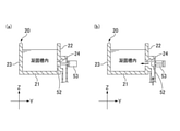
- the coagulation tank 20 has an opening / closing member that opens and closes the supply port 24 to prevent liquid leakage and backflow from the supply port 24.
- a shutter-type lid 50 that can be opened and closed by a cylinder 53 is provided on the side wall 22 having the supply port 24.
- the shutter-type lid 50 is closed while the partition blade 13 passes through the supply port 24.
- the rear partition blade 13 comes to the lowermost end, and there is no leakage of soymilk coagulant between the side walls 22 and 23 and the inner surface of the bottom wall 21. From the state where the sealing property is firmly secured, the shutter-type lid 50 is opened, and soymilk containing a coagulant is weighed and poured into the coagulation section of the coagulation tank 20 almost under the liquid level for a predetermined time.
- the shutter-type lid 50 When the weighing is completed, the shutter-type lid 50 is closed. That is, the partition blade 13 may be driven continuously or in batch, but the soymilk containing the coagulant is supplied in batch. Further, the shutter-type lid 50 may be opened to supply soymilk containing a coagulant at least until the partition blade 13 overlaps the supply port 24 again.
- the semi-ripened or uncoagulated soymilk coagulant containing a coagulant leaks backward before and after the partition blades 13 that orbit continuously overlap. Therefore, as in the first modification shown in FIG. 11, it is preferable to use a shutter-type lid 51 that can be opened and closed up and down without a step between the inner surface of the side wall 22 and the lid surface in the closed state. Further, as in the second modification shown in FIG. 12, even in a form in which a commercially available sanitary tank valve (tank bottom valve) 52 is used and the tip portion of the valve 52 closes the inner surface of the side wall 22 without a step in the closed state. good.
- soymilk containing a coagulant is supplied in accordance with the opening and closing of the opening / closing members (shutter type lid 51, tank valve 52) at the timing when the partition blade 13 and the supply port 24 overlap. Will be intermittent (batch type supply).
- the opening / closing member when the opening / closing member is not provided in the supply port 24 as in the above embodiment, it is preferable to provide the supply port 24 above the liquid level of the soymilk containing the coagulant to be supplied to the coagulation section.
- the supply of soymilk containing a coagulant may be continuous.
- the liquid level is not so high and the moving speed of the partition blade 13 is not so slow (passing through the supply port 24). In this case, the moving speed may be increased for a moment.) Since the amount of leakage is small and there is no problem, in this case as well, the opening / closing member itself may not be provided.
- the rubber scraper 13a is formed long in the width direction, and the side wall 22 ,.
- the supply port 24 of 23 is temporarily closed.
- the rubber scraper 13a can also be applied when the supply port 24 is provided only on one side wall.
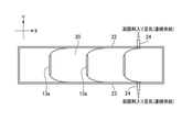
- the fourth modification shown in FIG. 14 when the supply port 24 is formed on the bottom wall 21 of the coagulation tank 20, the rubber scraper 13b is formed long in the vertical direction, and the supply port 24 of the bottom wall 21 is formed. I try to temporarily block it. In the case of the third and fourth modifications, soymilk containing a coagulant may be continuously supplied.
- two supply ports 24a and 24b are provided at positions close to one side wall 22 of the coagulation tank 20, soymilk containing a coagulant is continuously supplied, and a three-way valve 56 is used.
- the supply port is switched to supply to the continuous coagulator.
- the supply direction is changed by the three-way valve 56, the supply from the supply port 24b is not performed, and the supply from the supply port 24a is continued.
- the soymilk containing the coagulant is continuously supplied, and the partition blade 13 is also continuously driven.
- each supply port is provided with an opening / closing member such as a tank valve.
- the soymilk containing the coagulant is supplied to the compartment A by the flow path on the right side, while the flow path on the left side overlaps with the partition blade 13 and is closed.
- the three-way valve 56 is switched and soymilk containing a coagulant is supplied to the section B through the flow path on the right side. After that, the soymilk containing the coagulant is continuously supplied by repeating this process. Therefore, unlike batch-type solidification, edge cutting is not required, uneven solidification is reduced, and more uniform solidification quality is obtained.
- a switching valve may be provided according to the number of supply ports 24.
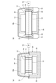
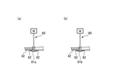
- the upper surface of the protective plate 61 can be firmly broken down to the bottom of the soymilk coagulant, the water can be separated from the lower cloth 42, and the drainage can be improved. Furthermore, it is possible to obtain tofu that is hard and has uniform hardness. Therefore, in the past, in order to protect the lower cloth 42, it was broken at a height of 5 to 10 mm above the lower cloth 42, so that the bottom surface hardly collapses and the problem of becoming "two-layer tofu" is solved. Can be done.
- the upper surface of the protective plate 61 is arranged so as to be flush with the portion of the lower cloth 42 on the upstream side and the downstream side with respect to the position below the breaking device 60, so that the soymilk coagulated product can be smoothly conveyed. can.
- the protective plate 61 to which the breaking device 60 can come into contact may also have the function of the guide roll 63, and specifically, protects the protective plate 61.
- the plates 61a and 61b have a thickness that does not damage the lower cloth 42, and are chamfered with rounded corners.
- the protective plate 61a of FIG. 17A has an elliptical shape in which both the upper surface side and the lower surface side are curved, and the protective plate 61b of FIG. 17B has a flat upper surface side and a curved lower surface side. ing.
- the protective plate 61 may be made of a rigid metal such as stainless steel, or may be made of a resin or rubber and made of an elastic material.
- the pudding-like and soft soymilk coagulant can be made into silken tofu or soybean flower (tofu flower) without pressing it as it is. Further, the pudding-like coagulated soymilk can be lightly pressed and only the texture is applied to make soft tofu.
- the pudding-like coagulated soymilk is appropriately crushed to a desired degree by the crushing device 60 and pressed to produce cotton tofu, fried tofu / fried tofu, hard tofu, and tofu.
- Fried tofu, hard tofu, and shimadofu are generally produced from rag-like coagulant, but it can also be produced by finely breaking the pudding-like coagulant obtained from thin soymilk. It becomes a tofu that retains water and does not easily lose its taste, and it becomes easier to maintain a delicious state even if it is stored for a long time such as boil sterilization.
- the continuous coagulator 10 produces soymilk having a solid content of 3 to 20% wt, preferably 5 to 15% wt at 50 to 95 ° C (preferably 60 to 85 ° C).
- soymilk having a solid content of 3 to 20% wt, preferably 5 to 15% wt at 50 to 95 ° C (preferably 60 to 85 ° C).
- the coagulated product may be separated from the "yu", which is a so-called “rag-like” coagulation state. You can expect it.
- a slow-acting coagulant in which the time from mixing with soymilk to the start of coagulation is 5 to 180 seconds, preferably 10 to 120 seconds, and emulsified bittern can also be preferably used.
- a commercially available slow-acting coagulant may be used, and in addition to emulsified bittern in which magnesium chloride is wrapped in oil or an emulsifier, for example, GDL (glucono delta lactone), sushi powder (calcium sulfate, coarse granules), salt.
- GDL glucono delta lactone
- sushi powder calcium sulfate, coarse granules
- salt for example, GDL (glucono delta lactone), sushi powder (calcium sulfate, coarse granules), salt.
- Use slow-acting coagulants such as transglutaminase.
- a gelling auxiliary material such as agar, carrageenan, curdlan, and starch. Further, a manufacturing method in which these are appropriately blended may be used. When emulsified bittern is used as the coagulant, the sweetness can also be increased.
- a pH adjuster such as baking soda
- a polyphosphoric acid-based additive having a chelating action may be used in combination with soymilk.
Landscapes
- Engineering & Computer Science (AREA)
- Life Sciences & Earth Sciences (AREA)
- Chemical & Material Sciences (AREA)
- Food Science & Technology (AREA)
- Polymers & Plastics (AREA)
- Mechanical Engineering (AREA)
- Agronomy & Crop Science (AREA)
- Botany (AREA)
- Health & Medical Sciences (AREA)
- Nutrition Science (AREA)
- Manufacturing & Machinery (AREA)
- Beans For Foods Or Fodder (AREA)
Abstract
This soybean curd production device has: a boat-shaped continuous coagulation machine which has an endless conveyor having a plurality of separation blades attached at predetermined intervals on the surface of the conveyor belt, and a coagulation tank through which the separation blades pass and which has a concave cross-sectional shape; and a continuous molding machine which has at least a lower side endless conveying conveyor around which lower cloth is wound, and an upper side endless conveying conveyor around which upper cloth is wound. When viewed from above, the lower side endless conveying conveyor overlaps the coagulation tank so that the lower cloth is positioned below an outlet end of the coagulation tank. The bottom wall of the coagulation tank is formed substantially parallel from the vicinity of an inlet of the coagulation tank toward the outlet end. This makes it possible to deliver a substantially pudding-like soymilk coagulate onto the lower cloth of the continuous molding machine from the continuous coagulation machine without damaging the coagulate while ensuring quantitativity.
Description
本発明は、連続凝固機と連続成型機とを有する豆腐類製造装置及び豆腐類製造方法に関する。
The present invention relates to a tofu manufacturing apparatus and a tofu manufacturing method having a continuous coagulator and a continuous molding machine.
従来、舟形の連続凝固機を有する豆腐類製造装置としては、種々のものが知られている(例えば、特許文献1~4参照)。
特許文献1及び2では、自動凝固部には豆乳を凝固させたとうふ種を、投入口を介して、自動成型部へ送ることが記載されている。特に、特許文献1には、極端なとうふの砕きは良質の製品を得られず、とうふ種をなるべく砕かないで、厚い長いとうふを作るため、成型部へのとうふの送り込みは、その緩慢な落下ととうふ種の量の定量化が投入口においてバランスウェイトのある梃子付きダンパーで行われることが記載されている。 Conventionally, various tofu manufacturing devices having a boat-shaped continuous coagulator are known (see, for example, Patent Documents 1 to 4).
Patent Documents 1 and 2 describe that the tofu seeds obtained by coagulating soymilk are sent to the automatic molding section via the charging port in the automatic coagulation section. In particular, according to Patent Document 1, extreme crushing of tofu does not give a good quality product, and tofu seeds are not crushed as much as possible to make a thick and long tofu. It is stated that the amount of tofu seeds is quantified with a balanced weighted damper at the inlet.
特許文献1及び2では、自動凝固部には豆乳を凝固させたとうふ種を、投入口を介して、自動成型部へ送ることが記載されている。特に、特許文献1には、極端なとうふの砕きは良質の製品を得られず、とうふ種をなるべく砕かないで、厚い長いとうふを作るため、成型部へのとうふの送り込みは、その緩慢な落下ととうふ種の量の定量化が投入口においてバランスウェイトのある梃子付きダンパーで行われることが記載されている。 Conventionally, various tofu manufacturing devices having a boat-shaped continuous coagulator are known (see, for example, Patent Documents 1 to 4).
しかしながら、特許文献1及び2では、自動凝固部は、自動成型部の上部キャタピラの上部に配置される2階建ての構成である以上、自動凝固部と自動成型部との間には落差は相当にあり、豆腐の崩れは少なからず起きる。また、豆腐の送り込みをダンパーで行う場合、投入量の変動を多少和らげる効果はあっても、大量に落下するときは投入口が大きく開き、少量の時は投入口が閉じる動作となり、特に大豆品質変化による豆腐の堅さの変動があると、定量性に乏しい。
However, in Patent Documents 1 and 2, since the automatic solidifying portion has a two-story structure arranged above the upper caterpillar of the automatic molding portion, the difference between the automatic solidifying portion and the automatic molding portion is considerable. The tofu crumbles not a little. In addition, when tofu is fed with a damper, the input port opens wide when a large amount of tofu is dropped, and the input port closes when a small amount of tofu is dropped, even though it has the effect of alleviating fluctuations in the input amount, especially soybean quality. If there is a change in the firmness of tofu due to changes, it is poorly quantitative.
本発明は、上述した課題に鑑みて為されたものであり、定量性を確保しつつ、豆乳凝固物を崩さずに、連続凝固機から連続成型機の下布の上に供給することができる豆腐類製造装置及び豆腐類製造方法を提供することにある。
The present invention has been made in view of the above-mentioned problems, and can be supplied from a continuous coagulant onto the lower cloth of a continuous molding machine without breaking the soymilk coagulant while ensuring quantitativeness. The present invention is to provide a tofu manufacturing apparatus and a tofu manufacturing method.
本発明の上記目的は、以下の構成によって達成される。
(1) コンベアベルトの表面に所定の間隔で複数の仕切り羽根が取り付けられた無端状コンベアと、前記仕切り羽根が内部を通過する、断面凹状の凝固槽と、を有する舟形の連続凝固機と、
下布が巻回される下側の無端状搬送コンベアと上布が巻回される上側の無端状搬送コンベアと、を少なくとも有する連続成型機と、
を有する豆腐類製造装置であって、
前記下側の無端状搬送コンベアは、前記下布が前記凝固槽の出口端部の下方に位置するように、上方から見て前記凝固槽とオーバーラップし、
前記凝固槽の底壁は、前記凝固槽の入口付近から該出口端部に向かって略水平に形成される、豆腐類製造装置。
(2) 前記凝固槽と前記上側の無端状搬送コンベアとは、直線状に並んで配置されている、(1)に記載の豆腐類製造装置。
(3) 前記連続凝固機の無端状コンベアは、前記凝固槽の出口付近において、前記仕切り羽根の先端ないし取付端がせり上がるように、前記連続凝固機の送り方向に向かって上方に傾斜する、(1)又は(2)に記載の豆腐類製造装置。
(4) 前記連続凝固機は、前記凝固槽の入口付近において、前記凝固槽の両側壁及び底壁の少なくとも1か所に、豆乳、凝固剤、及び凝固剤入り豆乳あるいは洗浄薬液のいずれかを供給する供給口ないしはそれらを排出する排出口を有する、(1)~(3)のいずれかに記載の豆腐類製造装置。
(5) 前記凝固槽は、前記供給口を開閉する開閉部材を有する、(4)に記載の豆腐類製造装置。
(6) 前記開閉部材は、前記供給口が開口する前記凝固槽の側壁に形成された窪みを埋め、前記供給口を平坦に塞ぐように配置される、(5)に記載の豆腐類製造装置。
(7) 前記仕切り羽根は、ゴム製のスクレーパーであり、
前記開閉部材は、前記凝固槽の内面と接触して撓むことで前記供給口を塞ぐ、前記ゴム製のスクレーパーによって構成される、(5)又は(6)に記載の豆腐類製造装置。
(8) 前記連続凝固機は、前記連続成型機と同期駆動される、(1)~(7)のいずれかに記載の豆腐類製造装置。
(9) 前記凝固槽の幅は、前記連続成型機のプレス部の幅とほぼ等しい、(1)~(8)のいずれかに記載の豆腐類製造装置。
(10) 前記凝固槽と、前記上側の無端状搬送コンベアとの間で、前記下側の無端状搬送コンベアの下布の上方には、崩し装置が設けられ、
前記崩し装置の下方の位置では、前記崩し装置が当接可能な保護板が配置され、
前記下側の無端状搬送コンベアの下布は、前記保護板を迂回するように、下方に押し下げられて案内される、(1)~(9)のいずれかに記載の豆腐類製造装置。
(11) 前記連続凝固機は、前記無端状コンベアの上方を覆うカバーをさらに備える、(1)~(10)のいずれかに記載の豆腐類製造装置。
(12) 前記無端状コンベアでは、前記コンベアベルトを連結するチェーン、及び該チェーンが掛け渡されるスプロケットが、前記凝固槽の側壁の幅方向外側に配置される、(1)~(11)のいずれかに記載の豆腐類製造装置。
(13) (1)~(12)のいずれかに記載の豆腐類製造装置を用いて豆腐類を製造する豆腐類製造方法であって、
前記連続凝固機は、50~95℃、固形分が3~20%wtの豆乳を凝固剤によって凝固熟成させることで、ほぼプリン状の豆乳凝固物を生成し、
前記連続成型機は、前記下布で前記豆乳凝固物を搬送し、必要に応じてプレスすることで、前記豆腐類を成型する、豆腐類製造方法。
(14) 前記凝固剤は、遅効性凝固剤、又は乳化苦汁である、(13)に記載の豆腐類製造方法。
なお、本明細書において、「ほぼプリン状の豆乳凝固物」とは、凝固熟成後の凝固物の状態で、離水が20%以下、好ましくは10%以下である状態を言う。 The above object of the present invention is achieved by the following configuration.
(1) A boat-shaped continuous coagulator having an endless conveyor in which a plurality of partition blades are attached to the surface of a conveyor belt at predetermined intervals, and a coagulation tank having a concave cross section through which the partition blades pass inside.
A continuous molding machine having at least a lower endless conveyor on which the lower cloth is wound and an upper endless conveyor on which the upper cloth is wound.
It is a tofu manufacturing equipment with
The lower endless conveyor overlaps the coagulation tank when viewed from above so that the lower cloth is located below the outlet end of the coagulation tank.
The bottom wall of the coagulation tank is a tofu manufacturing apparatus formed substantially horizontally from the vicinity of the inlet of the coagulation tank toward the end of the coagulation tank.
(2) The tofu manufacturing apparatus according to (1), wherein the coagulation tank and the upper endless transport conveyor are arranged side by side in a straight line.
(3) The endless conveyor of the continuous coagulator inclines upward toward the feed direction of the continuous coagulator so that the tip or the mounting end of the partition blade rises near the outlet of the coagulation tank. The tofu manufacturing apparatus according to (1) or (2).
(4) The continuous coagulant puts soymilk, a coagulant, and soymilk containing a coagulant or a cleaning agent solution on at least one of the side walls and the bottom wall of the coagulant near the inlet of the coagulant. The tofu manufacturing apparatus according to any one of (1) to (3), which has a supply port for supplying or a discharge port for discharging them.
(5) The tofu manufacturing apparatus according to (4), wherein the coagulation tank has an opening / closing member for opening / closing the supply port.
(6) The tofu manufacturing apparatus according to (5), wherein the opening / closing member fills a recess formed in a side wall of the coagulation tank in which the supply port opens, and is arranged so as to flatly close the supply port. ..
(7) The partition blade is a rubber scraper.
The tofu manufacturing apparatus according to (5) or (6), wherein the opening / closing member is composed of a rubber scraper that closes the supply port by coming into contact with the inner surface of the coagulation tank and bending.
(8) The tofu manufacturing apparatus according to any one of (1) to (7), wherein the continuous coagulator is driven synchronously with the continuous molding machine.
(9) The tofu manufacturing apparatus according to any one of (1) to (8), wherein the width of the coagulation tank is substantially equal to the width of the press portion of the continuous molding machine.
(10) A breaking device is provided between the coagulation tank and the upper endless transport conveyor above the lower cloth of the lower endless transport conveyor.
At a position below the breaking device, a protective plate with which the breaking device can come into contact is arranged.
The tofu manufacturing apparatus according to any one of (1) to (9), wherein the lower cloth of the lower endless transport conveyor is pushed down and guided so as to bypass the protective plate.
(11) The tofu production apparatus according to any one of (1) to (10), wherein the continuous coagulator further includes a cover that covers the upper part of the endless conveyor.
(12) In the endless conveyor, any of (1) to (11), wherein the chain connecting the conveyor belt and the sprocket to which the chain is hung are arranged on the outer side in the width direction of the side wall of the solidification tank. The tofu manufacturing equipment described in Crab.
(13) A tofu manufacturing method for producing tofu using the tofu manufacturing apparatus according to any one of (1) to (12).
The continuous coagulator produces almost purine-like soymilk coagulant by coagulating and aging soymilk at 50 to 95 ° C. and a solid content of 3 to 20% wt with a coagulant.
The continuous molding machine is a method for producing tofu, in which the soymilk coagulant is conveyed by the lower cloth and pressed as necessary to mold the tofu.
(14) The method for producing tofu according to (13), wherein the coagulant is a slow-acting coagulant or emulsified bittern.
In the present specification, the "almost purine-like soymilk coagulant" refers to a state of the coagulated product after coagulation and aging, in which the water separation is 20% or less, preferably 10% or less.
本発明によれば、定量性を確保しつつ、豆乳凝固物を崩さずに、連続凝固機から連続成型機の下布の上に供給することができる。
According to the present invention, the soymilk coagulated product can be supplied from the continuous coagulant onto the lower cloth of the continuous molding machine while ensuring the quantitativeness.
以下、本発明の各実施形態に係る豆腐類製造装置及び豆腐類製造方法について、図面を参照して詳細に説明する。
Hereinafter, the tofu manufacturing apparatus and the tofu manufacturing method according to each embodiment of the present invention will be described in detail with reference to the drawings.
(第1実施形態)
図1に示すように、第1実施形態の豆腐類製造装置1は、豆乳と凝固剤がミキサー2によって混合された凝固剤入り豆乳を凝固・熟成して、プリン状の豆乳凝固物を生成する舟形の連続凝固機10と、豆乳凝固物を脱水しながら豆腐類に成型する連続成型機30と、を備える。
豆乳と凝固剤は、貯留される豆乳タンクT1及び凝固剤タンクT2から、定量ポンプP1,P2で所定の流量を送液し、ミキサー2で混合して、凝固剤入り豆乳として連続凝固機10に供給される。なお、連続凝固機10には、豆乳、凝固剤が別々に直接供給されて凝固槽20内で混合されてもよい。いずれにしても、大部分(1区画の凝固剤入り豆乳の50%以上)が液面下に供給されることが好ましい。 (First Embodiment)
As shown in FIG. 1, the tofu manufacturing apparatus 1 of the first embodiment coagulates and matures soymilk containing a coagulant in which soymilk and a coagulant are mixed by amixer 2 to produce a pudding-like soymilk coagulant. A boat-shaped continuous coagulator 10 and a continuous molding machine 30 for molding soymilk coagulant into tofu while dehydrating it are provided.
The soymilk and the coagulant are sent from the stored soymilk tank T1 and the coagulant tank T2 at a predetermined flow rate by the metering pumps P1 and P2, mixed by themixer 2, and sent to the continuous coagulant 10 as soymilk containing the coagulant. Will be supplied. The soymilk and the coagulant may be directly supplied separately to the continuous coagulant 10 and mixed in the coagulation tank 20. In any case, it is preferable that the majority (50% or more of the soymilk containing the coagulant in one section) is supplied below the liquid surface.
図1に示すように、第1実施形態の豆腐類製造装置1は、豆乳と凝固剤がミキサー2によって混合された凝固剤入り豆乳を凝固・熟成して、プリン状の豆乳凝固物を生成する舟形の連続凝固機10と、豆乳凝固物を脱水しながら豆腐類に成型する連続成型機30と、を備える。
豆乳と凝固剤は、貯留される豆乳タンクT1及び凝固剤タンクT2から、定量ポンプP1,P2で所定の流量を送液し、ミキサー2で混合して、凝固剤入り豆乳として連続凝固機10に供給される。なお、連続凝固機10には、豆乳、凝固剤が別々に直接供給されて凝固槽20内で混合されてもよい。いずれにしても、大部分(1区画の凝固剤入り豆乳の50%以上)が液面下に供給されることが好ましい。 (First Embodiment)
As shown in FIG. 1, the tofu manufacturing apparatus 1 of the first embodiment coagulates and matures soymilk containing a coagulant in which soymilk and a coagulant are mixed by a
The soymilk and the coagulant are sent from the stored soymilk tank T1 and the coagulant tank T2 at a predetermined flow rate by the metering pumps P1 and P2, mixed by the
なお、本実施形態の豆腐類製造装置1は、連続凝固機10が凝固剤入り豆乳の送り方向と連続成型機30が豆乳凝固物の送り方向が同じ方向となるように、連続凝固機10と連続成型機30とが直線状に並んで配置されている。設置スペースは広がるが、柔らかなほぼプリン状の凝固物をあまり崩さずに定量的に乗り移らせることができる。ここでは、連続凝固機10と連続成型機30とが並ぶ水平方向をX方向とし、X方向と直交する水平方向である、連続凝固機10及び連続成型機30の幅方向をY方向とし、連続凝固機10及び連続成型機30の上下方向をZ方向とする。
The tofu manufacturing apparatus 1 of the present embodiment has a continuous coagulator 10 so that the continuous coagulant 10 feeds the soymilk containing the coagulant and the continuous molding machine 30 feeds the soymilk coagulant in the same direction. The continuous molding machine 30 and the continuous molding machine 30 are arranged side by side in a straight line. Although the installation space is widened, the soft, almost pudding-like coagulum can be transferred quantitatively without breaking it too much. Here, the horizontal direction in which the continuous coagulator 10 and the continuous molding machine 30 are lined up is the X direction, and the width direction of the continuous coagulator 10 and the continuous molding machine 30, which is the horizontal direction orthogonal to the X direction, is the Y direction, and is continuous. The vertical direction of the coagulator 10 and the continuous molding machine 30 is the Z direction.
舟形の連続凝固機10はコンベアベルト(無端チェーン)12の表面に所定の間隔で複数の仕切り羽根13が取り付けられた無端状コンベア11と、仕切り羽根13が内部を通過する、断面凹状のステンレス製の凝固槽20と、無端状コンベア11の上方を覆うカバー29と、を主に有する。
The boat-shaped continuous coagulator 10 is made of an endless conveyor 11 on which a plurality of partition blades 13 are attached to the surface of a conveyor belt (endless chain) 12 at predetermined intervals, and a stainless steel having a concave cross section through which the partition blades 13 pass through. It mainly has a coagulation tank 20 and a cover 29 that covers the upper part of the endless conveyor 11.
無端状コンベア11は、凝固槽20の入口付近と出口付近に、略水平に並んで配置される2つのローラ14,15の回りにコンベアベルト(無端チェーン)12を掛け渡し、2つのローラ14,15の回転によりコンベアベルト(無端チェーン)12及び複数の仕切り羽根13を周回する。
In the endless conveyor 11, the conveyor belt (endless chain) 12 is hung around the two rollers 14 and 15 arranged substantially horizontally in the vicinity of the inlet and the outlet of the coagulation tank 20, and the two rollers 14 ,. The rotation of 15 orbits the conveyor belt (endless chain) 12 and the plurality of partition blades 13.
連続凝固機10のコンベアベルト(無端チェーン)12は、スチールベルト、ステンレスやチタン等の剛性のある金属製ベルトやチェーンやワイヤーであって、仕切り羽根を多数固定できるものであれば特に限定しない。
The conveyor belt (endless chain) 12 of the continuous coagulator 10 is not particularly limited as long as it is a steel belt, a rigid metal belt such as stainless steel or titanium, a chain, or a wire and can fix a large number of partition blades.
複数の仕切り羽根13は、ステンレスやチタン等の金属鋼製板部材13とゴム製部材13bから成り、幅方向に長く縦方向に短い長方形状を有しており、豆乳や「ゆ」などの液が漏れないように柔軟なNBRやEPDM、FKM等の(フッ素ゴム)、シリコンゴムなどのゴム製シール部材13bで凝固槽20の底壁21及び両側壁22,23の内面と内接又は接触する大きさを有する。したがって、連続凝固機10は、隣り合う仕切り羽根13と凝固槽20とによって凝固区画を形成する。
The plurality of partition blades 13 are composed of a metal steel plate member 13 such as stainless steel or titanium and a rubber member 13b, and have a rectangular shape that is long in the width direction and short in the vertical direction, and is a liquid such as soy milk or "yu". A rubber sealing member 13b such as flexible NBR, EPDM, FKM, etc. (fluororubber), silicon rubber, etc., inscribes or contacts the bottom wall 21 of the coagulation tank 20 and the inner surfaces of both side walls 22, 23 so as not to leak. Has a size. Therefore, the continuous coagulator 10 forms a coagulation section by the adjacent partition blades 13 and the coagulation tank 20.
凝固槽20の底壁21は、凝固剤入り豆乳を供給する入口付近においては、仕切り羽根13の先端の軌道に合わせて湾曲している一方、出口端部21aから入口付近に向かって湾曲部分まで略水平に形成されている。
The bottom wall 21 of the coagulation tank 20 is curved in accordance with the trajectory of the tip of the partition blade 13 in the vicinity of the inlet for supplying soymilk containing a coagulant, while from the outlet end 21a to the curved portion toward the inlet. It is formed almost horizontally.
また、凝固槽20の入口付近の側壁22,23の少なくとも一方には、凝固剤入り豆乳を供給するための供給口24が設けられている。したがって、供給口24から供給された凝固剤入り豆乳は、仕切り羽根13が連続凝固機10の出口付近に向けて移動することで、凝固・熟成される。なお、供給口には、後述する第2実施形態の開閉部材が設けられてもよい。
Further, at least one of the side walls 22 and 23 near the inlet of the coagulation tank 20 is provided with a supply port 24 for supplying soymilk containing a coagulant. Therefore, the soymilk containing the coagulant supplied from the supply port 24 is coagulated and aged by the partition blade 13 moving toward the outlet of the continuous coagulator 10. The supply port may be provided with an opening / closing member according to a second embodiment described later.
また、カバー29は、戻り部分に位置する複数の仕切り羽根13全体の上方を覆うように、仕切り羽根13の先端の軌道に合わせて形成されている。これにより、生産中、空気中の落下菌による二次汚染を防ぐとともに、凝固熟成工程での保温性を高めることができる。
Further, the cover 29 is formed so as to cover the upper part of the entire plurality of partition blades 13 located at the return portion in accordance with the trajectory of the tip of the partition blade 13. As a result, it is possible to prevent secondary contamination due to falling bacteria in the air during production and to improve heat retention in the coagulation and aging process.
連続成型機30は、上布32が巻回される上側の無端状搬送コンベア31と、下布42が巻回される下側の無端状搬送コンベア41と、を有する。下向きとなる上布32の表面と、上向きとなる下布42の表面とは、それぞれ略水平で、隙間を持って対向する。
The continuous molding machine 30 has an upper endless transfer conveyor 31 around which the upper cloth 32 is wound, and a lower endless transfer conveyor 41 around which the lower cloth 42 is wound. The surface of the upper cloth 32 facing downward and the surface of the lower cloth 42 facing upward are substantially horizontal and face each other with a gap.
上側の無端状搬送コンベア31と下側の無端状搬送コンベア41の各ローラの中心軸は、無端状コンベア11の2つのローラ14,15の中心軸と互いに平行に配置されている。
The central axes of the rollers of the upper endless conveyor 31 and the lower endless conveyor 41 are arranged parallel to the central axes of the two rollers 14 and 15 of the endless conveyor 11.
また、上布32や下布42は、柔軟性と強靭性があって、フッ素樹脂やポリエステル樹脂、ポリプロピレン樹脂、ポリエチレン樹脂などのモノフィラメントを平織、綾織など編み込まれた樹脂製濾布(例えば特許第4004413号等参照)であり、始端や後端では平巻状で、搬送面で底面と側壁を形成する樹脂製濾布ベルトステンレス等の金属製ワイヤーを編み込んだワイヤーネットベルト(メガネリンクベルトコンベア、フラットフレックスコンベア、チョコレートコンベア等)で、有孔ないし無孔の食品用樹脂ベルト(テフロンベルトや食品用ベルト)であればよい。
Further, the upper cloth 32 and the lower cloth 42 have flexibility and toughness, and are made of resin filter cloth (for example, patent No. 1) in which monofilaments such as fluororesin, polyester resin, polypropylene resin, and polyethylene resin are woven into plain weave or twill weave. (Refer to No. 400413, etc.), which is a flat-wound shape at the start and rear ends, and is a resin filter cloth belt that forms the bottom surface and side walls on the transport surface. A flat flex conveyor, chocolate conveyor, etc.) may be used as long as it is a perforated or non-perforated food resin belt (Teflon belt or food belt).
上側の無端状搬送コンベア31と下側の無端状搬送コンベア41は、豆乳凝固物を上下から挟んでプレスして、脱水しながら豆腐類を成型し、下流工程に搬送する。
The upper endless transfer conveyor 31 and the lower endless transfer conveyor 41 sandwich the soymilk coagulant from above and below and press it to form tofu while dehydrating and transport it to the downstream process.
ここで、下側の無端状搬送コンベア41は、下布42が凝固槽20の底壁21の出口端部21aの下方に位置するように、上方から見て凝固槽20とオーバーラップしている。即ち、下側の無端状搬送コンベア41は、凝固槽20の下方に近接して位置するように、上側の無端状搬送コンベア31よりも連続凝固機側に延長して構成される。
Here, the lower endless conveyor 41 overlaps the coagulation tank 20 when viewed from above so that the lower cloth 42 is located below the outlet end 21a of the bottom wall 21 of the coagulation tank 20. .. That is, the lower endless transfer conveyor 41 is configured to extend closer to the continuous coagulator side than the upper endless transfer conveyor 31 so as to be located close to the lower part of the coagulation tank 20.
また、凝固槽20と上側の無端状搬送コンベア41とは、下側の無端状搬送コンベア41の下布42の上方で、X方向に直線状に並んで配置されている。
Further, the coagulation tank 20 and the upper endless transfer conveyor 41 are arranged in a straight line in the X direction above the lower cloth 42 of the lower endless transfer conveyor 41.
また、連続凝固機10は、連続成型機30と同期駆動される。即ち、連続凝固機10との無端状コンベア11のコンベアベルト(無端チェーン)12と、連続成型機30の上側の無端状搬送コンベア31の上布32と、下側の無端状搬送コンベア41の下布42とは、それぞれの送り部分において同速で同じ方向に連続駆動される。
Further, the continuous coagulator 10 is driven synchronously with the continuous molding machine 30. That is, the conveyor belt (endless chain) 12 of the endless conveyor 11 with the continuous coagulator 10, the upper cloth 32 of the endless transfer conveyor 31 on the upper side of the continuous molding machine 30, and the lower endless transfer conveyor 41. The cloth 42 is continuously driven in the same direction at the same speed at each feed portion.
これにより、凝固槽20の底壁21の出口端部21aと下側の無端状搬送コンベア41の下布42とは落差が小さい状態となり、豆乳凝固物は、分配器や投入器を介さずに、連続凝固機10から搬出されるプリン状の豆乳凝固物の慣性力をそのままに、直接下布42に移載することができる。また、仕切り羽根13によって仕切られた凝固区画によって、定量性を確保しながら、豆乳凝固物を下布42上に移載することができる。
As a result, the head of the outlet end 21a of the bottom wall 21 of the coagulation tank 20 and the lower cloth 42 of the lower endless conveyor 41 are in a small state, and the soymilk coagulant does not go through the distributor or the input device. , The inertial force of the pudding-like soymilk coagulant carried out from the continuous coagulator 10 can be directly transferred to the lower cloth 42. Further, the soymilk coagulated product can be transferred onto the lower cloth 42 while ensuring the quantitativeness by the coagulation section partitioned by the partition blade 13.
従来のような、成型機の上方に凝固機が配置される2階建ての構造では、豆乳凝固物は落差で必ず砕かれた状態になり、また、凝固槽の出口では仕切り区分ごとに豆腐が一気に流れ出るため、凝固機の無端状コンベアは断続運転で、成型機もそれに合わせて断続運転するのが通常であった。また、凝固機と成型機とを連続運転した場合には、豆乳凝固物の盛り込みがムラになりやすかった。
一方、本実施形態の豆腐類製造装置1は、1階建ての地上配列で直線的なので、豆乳凝固物が一気に流れ出ることが抑えられ、柔らかいプリン状の豆乳凝固物を崩さずに、落差なくそのままソフトに下布42上に移載できる。また、豆腐類製造装置1のメンテナンスの際などに、高所での作業が減り、作業安全性も高まる。 In the conventional two-story structure where the coagulant is placed above the molding machine, the soymilk coagulant is always in a crushed state due to the head, and tofu is produced in each partition division at the outlet of the coagulation tank. Since it flows out all at once, the endless conveyor of the coagulator is usually operated intermittently, and the molding machine is also operated intermittently accordingly. Further, when the coagulator and the molding machine were continuously operated, the soymilk coagulated product was likely to be incorporated unevenly.
On the other hand, since the tofu manufacturing apparatus 1 of the present embodiment has a one-story ground arrangement and is linear, the soymilk coagulant is suppressed from flowing out at once, and the soft pudding-like soymilk coagulant is not broken and remains as it is without a drop. Can be softly transferred onto thelower cloth 42. In addition, when the tofu manufacturing apparatus 1 is maintained, the work at a high place is reduced and the work safety is improved.
一方、本実施形態の豆腐類製造装置1は、1階建ての地上配列で直線的なので、豆乳凝固物が一気に流れ出ることが抑えられ、柔らかいプリン状の豆乳凝固物を崩さずに、落差なくそのままソフトに下布42上に移載できる。また、豆腐類製造装置1のメンテナンスの際などに、高所での作業が減り、作業安全性も高まる。 In the conventional two-story structure where the coagulant is placed above the molding machine, the soymilk coagulant is always in a crushed state due to the head, and tofu is produced in each partition division at the outlet of the coagulation tank. Since it flows out all at once, the endless conveyor of the coagulator is usually operated intermittently, and the molding machine is also operated intermittently accordingly. Further, when the coagulator and the molding machine were continuously operated, the soymilk coagulated product was likely to be incorporated unevenly.
On the other hand, since the tofu manufacturing apparatus 1 of the present embodiment has a one-story ground arrangement and is linear, the soymilk coagulant is suppressed from flowing out at once, and the soft pudding-like soymilk coagulant is not broken and remains as it is without a drop. Can be softly transferred onto the
例えば、破断力が60gf/cm2以上の硬めのプリン状の豆乳凝固物であれば、スチールベルトを用いた凝固機(特許3568193号)を適用することができるが、破断力が60gf/cm2未満、具体的には、1~40gf/cm2程度、特に、5~20gf/cm2程度の非常に柔らかいプリン状の豆乳凝固物の場合、スリップしたり、割れたりして、うまく搬送することができない。一方、本実施形態の連続凝固機10を用いることで、上記破断力の小さい非常に柔らかいプリン状の豆乳凝固物でもほぼ崩さずに搬送、乗り移りさせることができる。
For example, in the case of a hard pudding-like soymilk coagulant having a breaking force of 60 gf / cm 2 or more, a coagulant using a steel belt (Patent No. 3568193) can be applied, but the breaking force is 60 gf / cm 2. less, specifically, 1 ~ 40gf / cm 2 or so, especially in the case of 5 ~ 20gf / cm 2 about very soft pudding-like soy milk coagulum, or slip, and cracked, transport well I can't. On the other hand, by using the continuous coagulator 10 of the present embodiment, even the very soft pudding-like soymilk coagulated product having a small breaking force can be transported and transferred without being broken.
また、連続凝固機10は、連続成型機30と落差が少なく、かつ同期同速で駆動されることで、極めて柔らかいプリン状の豆乳凝固物をそのまま崩さずに、均等に連続成型機30の下布42上に移載することが可能になる。
連続凝固機10と連続成型機30は、断続運転(バッチ式)するより、機械の負担が少なく、駆動モータの起動電流値も少なく省エネルギーになる。また、バッチ駆動に比べて、長期間使用によるチェーンの伸びなどによるタイミングのずれの影響も少ない。 Further, thecontinuous coagulator 10 has a smaller head than the continuous molding machine 30 and is driven at the same speed at the same time, so that the extremely soft pudding-like soymilk coagulated product is not destroyed as it is, and is evenly under the continuous molding machine 30. It will be possible to transfer it on the cloth 42.
Thecontinuous coagulation machine 10 and the continuous molding machine 30 have less load on the machine and less starting current value of the drive motor than the intermittent operation (batch type), which saves energy. In addition, compared to batch drive, the effect of timing shift due to chain elongation due to long-term use is small.
連続凝固機10と連続成型機30は、断続運転(バッチ式)するより、機械の負担が少なく、駆動モータの起動電流値も少なく省エネルギーになる。また、バッチ駆動に比べて、長期間使用によるチェーンの伸びなどによるタイミングのずれの影響も少ない。 Further, the
The
さらに、連続凝固機10の凝固槽20の幅Aは、連続成型機30のプレス部(上布32のY方向幅)の幅Bとほぼ等しい。具体的に、凝固槽20の幅Aは、プレス部の幅Bに対して、80%~100%、好ましくは90%~100%である。実寸では、プレス部の幅Bは500~3,000mm(概ね1,000~2,000mm)である。
従来の油揚生地成型機では、おぼろ状(豆乳凝固物と黄緑色の「ゆ」が混合した凝固状態)の凝固状態であって、舟形の凝固機の凝固槽の幅は、成型機の成型幅より狭いのが一般的であるため、分配器(投入器)によって成型機幅に広げて均等に分配される。
一方、本実施形態では、連続凝固機10の凝固槽20の幅Aは、連続成型機30のプレス部の幅Bとほぼ等しいので、連続凝固機10と連続成型機30で豆乳凝固物を受け渡す際に、凝固機10から搬出されてくる非常に柔らかなほぼプリン状に凝固した豆乳凝固物を、崩さずにそのまま直接(分配器など介さずに)成型機30の下布42上にソフトランディングすることができる。 Further, the width A of thecoagulation tank 20 of the continuous coagulator 10 is substantially equal to the width B of the press portion (width in the Y direction of the upper cloth 32) of the continuous molding machine 30. Specifically, the width A of the coagulation tank 20 is 80% to 100%, preferably 90% to 100%, with respect to the width B of the press portion. In the actual size, the width B of the press portion is 500 to 3,000 mm (generally 1,000 to 2,000 mm).
In the conventional frying dough molding machine, it is in a rag-like (coagulation state in which soymilk coagulant and yellow-green "yu" are mixed), and the width of the coagulation tank of the boat-shaped coagulator is the molding width of the molding machine. Since it is generally narrower, it is spread evenly over the width of the molding machine by a distributor (loader).
On the other hand, in the present embodiment, the width A of thecoagulation tank 20 of the continuous coagulator 10 is substantially equal to the width B of the press portion of the continuous molding machine 30, so that the soymilk coagulant is received by the continuous coagulator 10 and the continuous molding machine 30. When handing over, the very soft, almost pudding-like coagulated soymilk that is carried out from the coagulator 10 is softened directly on the lower cloth 42 of the molding machine 30 without breaking it (without using a distributor or the like). You can land.
従来の油揚生地成型機では、おぼろ状(豆乳凝固物と黄緑色の「ゆ」が混合した凝固状態)の凝固状態であって、舟形の凝固機の凝固槽の幅は、成型機の成型幅より狭いのが一般的であるため、分配器(投入器)によって成型機幅に広げて均等に分配される。
一方、本実施形態では、連続凝固機10の凝固槽20の幅Aは、連続成型機30のプレス部の幅Bとほぼ等しいので、連続凝固機10と連続成型機30で豆乳凝固物を受け渡す際に、凝固機10から搬出されてくる非常に柔らかなほぼプリン状に凝固した豆乳凝固物を、崩さずにそのまま直接(分配器など介さずに)成型機30の下布42上にソフトランディングすることができる。 Further, the width A of the
In the conventional frying dough molding machine, it is in a rag-like (coagulation state in which soymilk coagulant and yellow-green "yu" are mixed), and the width of the coagulation tank of the boat-shaped coagulator is the molding width of the molding machine. Since it is generally narrower, it is spread evenly over the width of the molding machine by a distributor (loader).
On the other hand, in the present embodiment, the width A of the
また、凝固槽20の底壁21は、入口付近から出口端部21aに向かって略水平に形成されるので、落差がなく、少し遊離する水(いわゆる「ゆ」、「離水」「しみず」ともいう)の偏りを防ぐとともに、柔らかいほぼプリン状の豆乳凝固物と一緒にスムーズに搬送し、成型機への乗り移りの際に重力の影響による滑り台のような現象を防ぐことができる。
Further, since the bottom wall 21 of the coagulation tank 20 is formed substantially horizontally from the vicinity of the inlet toward the outlet end 21a, there is no head and a little free water (so-called “yu”, “separation”, and “water”). In addition to preventing bias, it can be smoothly transported together with soft, almost pudding-like coagulated soymilk, and can prevent a slide-like phenomenon due to the influence of gravity when transferring to a molding machine.
<変形例>
なお、上記実施形態では、凝固槽20の底壁21と下布42との間に隙間を有する構成としたが、図2に示す第1変形例のように、凝固槽20の出口端部21aを含む底壁21が下布42にほぼ接するように構成されてもよい。
これにより、凝固槽20の底壁21の出口端部21aと下側の無端状搬送コンベア41の下布42とは落差がさらに小さい状態となり、豆腐凝固物をより確実に崩さずに下布42上に移載することができる。 <Modification example>
In the above embodiment, a gap is provided between thebottom wall 21 of the coagulation tank 20 and the lower cloth 42, but as in the first modification shown in FIG. 2, the outlet end portion 21a of the coagulation tank 20 is provided. The bottom wall 21 including the cloth may be configured to be substantially in contact with the lower cloth 42.
As a result, the head of theoutlet end 21a of the bottom wall 21 of the coagulation tank 20 and the lower cloth 42 of the lower endless conveyor 41 becomes even smaller, and the lower cloth 42 does not break the tofu coagulant more reliably. Can be reprinted above.
なお、上記実施形態では、凝固槽20の底壁21と下布42との間に隙間を有する構成としたが、図2に示す第1変形例のように、凝固槽20の出口端部21aを含む底壁21が下布42にほぼ接するように構成されてもよい。
これにより、凝固槽20の底壁21の出口端部21aと下側の無端状搬送コンベア41の下布42とは落差がさらに小さい状態となり、豆腐凝固物をより確実に崩さずに下布42上に移載することができる。 <Modification example>
In the above embodiment, a gap is provided between the
As a result, the head of the
また、上記実施形態では、連続凝固機10の無端状コンベア11は、複数の仕切り羽根13の先端ないし取付端が、送り方向において、水平に移動するように構成していたが、図3に示す第2変形例のように、凝固槽20の出口付近において、せり上がって移動するように構成されてもよい。即ち、無端状コンベア11のコンベアベルト(無端チェーン)12は、仕切り羽根13の先端ないし取付端が漸次、上方に上がるように、連続凝固機10の送り方向に向かって上方に角度θ0だけ傾斜させる(0°≦θ0≦30°の範囲)。具体的には、コンベアベルト(無端チェーン)12を送り側から戻り側に転回して案内するローラ14のローラ15に対する高さtが豆乳凝固物の高さT以上となるように調整することが好ましい。このため、出口側のローラ14を入口側のローラ15よりも高く配置し、コンベアベルト(無端チェーン)12は、ガイドローラ25を通過したのち、仕切り羽根13と共にせり上がり、仕切り羽根13が下布42から徐々に離れるように構成される。
Further, in the above embodiment, the endless conveyor 11 of the continuous coagulator 10 is configured such that the tips or mounting ends of the plurality of partition blades 13 move horizontally in the feeding direction, as shown in FIG. As in the second modification, it may be configured to rise and move near the outlet of the coagulation tank 20. That is, the conveyor belt (endless chain) 12 of the endless conveyor 11 is inclined upward by an angle θ 0 toward the feeding direction of the continuous coagulator 10 so that the tip or the mounting end of the partition blade 13 gradually rises upward. (Range of 0 ° ≤ θ 0 ≤ 30 °). Specifically, it is possible to adjust the height t of the roller 14 for guiding the conveyor belt (endless chain) 12 from the feed side to the return side so that the height t with respect to the roller 15 is equal to or higher than the height T of the soymilk coagulant. preferable. Therefore, the roller 14 on the outlet side is arranged higher than the roller 15 on the inlet side, and the conveyor belt (endless chain) 12 rises together with the partition blade 13 after passing through the guide roller 25, and the partition blade 13 is used as a lower cloth. It is configured to gradually move away from 42.
仕切り羽根13の先端が、出口付近において、送り方向において水平に移動する場合、仕切り羽根13は、送り部分から戻り部分に反転する際に、豆乳凝固物の上端を蹴り上げて、多少崩してしまう可能性がある。
When the tip of the partition blade 13 moves horizontally in the feed direction near the outlet, the partition blade 13 kicks up the upper end of the soymilk coagulant and collapses to some extent when reversing from the feed portion to the return portion. there is a possibility.
一方、この変形例にように、仕切り羽根13を、出口付近において、上方に移動させることで、豆乳凝固物の上端を蹴り上げることがなくなり、豆乳凝固物が崩れるのを確実に防止できる。また、凝固熟成中、隣接する仕切り羽根13間(各凝固区画)に溜まった離水をより早く除去することもできる。
なお、無端状コンベア11は、コンベアベルト(無端チェーン)12の傾斜を任意に調整できるように構成されてもよい。 On the other hand, by moving thepartition blade 13 upward in the vicinity of the outlet as in this modification, the upper end of the soymilk coagulant is not kicked up, and the soymilk coagulant can be reliably prevented from collapsing. Further, during solidification and aging, the water separation accumulated between the adjacent partition blades 13 (each solidification section) can be removed more quickly.
Theendless conveyor 11 may be configured so that the inclination of the conveyor belt (endless chain) 12 can be arbitrarily adjusted.
なお、無端状コンベア11は、コンベアベルト(無端チェーン)12の傾斜を任意に調整できるように構成されてもよい。 On the other hand, by moving the
The
また、上記実施形態では、連続凝固機10は、凝固槽20の入口付近において、凝固槽20の側壁22に凝固剤入り豆乳を供給する供給口24を設けているが、図4に示す第3変形例のように、供給口24は、凝固槽20の底壁21に設けられてもよい。
なお、いずれの形態においても、供給口24は、液面レベルより下から凝固剤入り豆乳を流入させるのが泡立ちや泡かみを抑える上で好ましい。液面レベルとは、凝固区画内に供給される凝固入り豆乳の量が最も少ない豆腐類の場合を想定して設定される。 Further, in the above embodiment, thecontinuous coagulator 10 is provided with a supply port 24 for supplying soymilk containing a coagulant on the side wall 22 of the coagulation tank 20 near the inlet of the coagulation tank 20, but the third is shown in FIG. As in the modified example, the supply port 24 may be provided on the bottom wall 21 of the coagulation tank 20.
In any form, it is preferable to allow the soymilk containing the coagulant to flow into thesupply port 24 from below the liquid level in order to suppress foaming and foaming. The liquid level is set assuming the case of tofu having the smallest amount of coagulated soymilk supplied into the coagulation compartment.
なお、いずれの形態においても、供給口24は、液面レベルより下から凝固剤入り豆乳を流入させるのが泡立ちや泡かみを抑える上で好ましい。液面レベルとは、凝固区画内に供給される凝固入り豆乳の量が最も少ない豆腐類の場合を想定して設定される。 Further, in the above embodiment, the
In any form, it is preferable to allow the soymilk containing the coagulant to flow into the
例えば、凝固機10の入口側の上方から豆乳と凝固剤を流し込む場合、周回する仕切り羽根13に干渉しないように一定の距離で供給口24を設置するため、泡立ちや流入の勢いで凝固物に気泡が混じり、凝固が不均一になりやすかった。また凝固区画の空間が安定せず凝固ムラも生じやすかった。特に、無消泡剤の豆乳では非常に泡立ちやすく、著しい気泡の混入が起きた。
一方、上記実施形態や第3変形例では、凝固区画の空間の形状が固定した(直方体形状)状態であって、供給口24から凝固剤入り豆乳を流し込む際、大方は液面近くないしは液中に流し込むので、泡立ちは少なく、気泡の混入の少ない、均質なプリン状の豆乳凝固物が安定して得られやすい。仕切り板が戻り側から送り側に転回する位置では凝固区画形状が変化するため、転回する位置を過ぎて前後の仕切り板で区切られその後変化なく固定された凝固区画が形成されたところで、凝固剤入り豆乳を投入した方が保水性の高い凝固状態を安定して得ることができる。 For example, when soymilk and a coagulant are poured from above the inlet side of thecoagulant 10, the supply port 24 is installed at a certain distance so as not to interfere with the orbiting partition blade 13, so that the coagulant is foamed or inflows. Bubbles were mixed and the coagulation tended to be non-uniform. In addition, the space of the solidification section was not stable and uneven solidification was likely to occur. In particular, soymilk, which is a non-foaming agent, is very easy to foam, and significant air bubbles are mixed.
On the other hand, in the above embodiment and the third modification, the shape of the space of the coagulation section is fixed (rectangular parallelepiped shape), and when the soymilk containing the coagulant is poured from thesupply port 24, it is mostly near the liquid surface or in the liquid. Since it is poured into the soymilk, a homogeneous pudding-like soymilk coagulate with less foaming and less air bubbles can be stably obtained. Since the shape of the solidification section changes at the position where the partition plate turns from the return side to the feed side, the coagulant is formed when the solidification section is separated by the front and rear partition plates after the turning position and then fixed without change. It is possible to stably obtain a coagulated state with high water retention by adding soymilk containing soymilk.
一方、上記実施形態や第3変形例では、凝固区画の空間の形状が固定した(直方体形状)状態であって、供給口24から凝固剤入り豆乳を流し込む際、大方は液面近くないしは液中に流し込むので、泡立ちは少なく、気泡の混入の少ない、均質なプリン状の豆乳凝固物が安定して得られやすい。仕切り板が戻り側から送り側に転回する位置では凝固区画形状が変化するため、転回する位置を過ぎて前後の仕切り板で区切られその後変化なく固定された凝固区画が形成されたところで、凝固剤入り豆乳を投入した方が保水性の高い凝固状態を安定して得ることができる。 For example, when soymilk and a coagulant are poured from above the inlet side of the
On the other hand, in the above embodiment and the third modification, the shape of the space of the coagulation section is fixed (rectangular parallelepiped shape), and when the soymilk containing the coagulant is poured from the
なお、供給口24は、本実施形態の側壁1か所や、第3変形例の底壁1か所に限らず、両側壁の2か所、底壁に複数か所、両側壁と底壁の3箇所など、適宜設計されればよい。
The supply port 24 is not limited to one side wall of the present embodiment or one bottom wall of the third modification, but two supply ports on both side walls, a plurality of places on the bottom wall, and both side walls and the bottom wall. It may be appropriately designed, such as the three locations of.
また、図5に示す第4変形例のように、連続凝固機10は、カバー29の上方に、戻り部分に位置する仕切り羽根13を洗浄する洗浄部26や、カバー29内に蒸気を供給する蒸気供給装置27をさらに備えてもよい。洗浄部26の下方で、戻り部分に位置する仕切り羽根13やコンベアベルト(無端チェーン)12の下側に洗浄液を受ける受け皿28を設けてもよく、非生産時以外に、生産時も周回するごとに洗浄することができ、長時間生産時も衛生的な環境を維持できる。
また、洗浄する際には、供給口24は、凝固剤入り豆乳や洗浄薬液を排出する排出口としてもよく、或いは、排出口を凝固槽20の入口付近に別途設けてもよい。 Further, as in the fourth modification shown in FIG. 5, thecontinuous coagulator 10 supplies steam above the cover 29 to the cleaning unit 26 for cleaning the partition blade 13 located at the return portion and the inside of the cover 29. A steam supply device 27 may be further provided. A saucer 28 for receiving the cleaning liquid may be provided below the partition blade 13 and the conveyor belt (endless chain) 12 located at the return portion below the cleaning portion 26. It can be washed easily and can maintain a hygienic environment even during long-term production.
Further, when cleaning, thesupply port 24 may be a discharge port for discharging soymilk containing a coagulant or a cleaning chemical solution, or a discharge port may be separately provided near the inlet of the coagulation tank 20.
また、洗浄する際には、供給口24は、凝固剤入り豆乳や洗浄薬液を排出する排出口としてもよく、或いは、排出口を凝固槽20の入口付近に別途設けてもよい。 Further, as in the fourth modification shown in FIG. 5, the
Further, when cleaning, the
蒸気供給装置27によって蒸気をカバー29内に供給することで、豆乳凝固物を所定温度に保温することができる。豆乳凝固物から発生する湯気とともに、飽和蒸気で60~100℃でカバー29内の空間を維持することで、雑菌の繁殖を防き、衛生的に豆乳凝固物を搬送することができる。
By supplying steam into the cover 29 by the steam supply device 27, the soymilk coagulated product can be kept at a predetermined temperature. By maintaining the space inside the cover 29 with saturated steam at 60 to 100 ° C. together with the steam generated from the soymilk coagulum, it is possible to prevent the growth of germs and hygienically transport the soymilk coagulation.
また、洗浄部26により、薬液によるCIP(Cleaning in place)洗浄や、蒸気又は熱水や薬液による殺菌を行うことができる。舟形の連続凝固機10は仕切り羽根13が周回するため、仕切り羽根13(ステンレス鋼やゴムベラからなる部品)に付着する豆腐カスが長時間経つと不衛生なため、生産中は仕切り羽根13の周回軌道の戻り部分にて高圧洗浄ノズルを備えた洗浄部26を設けて豆腐カスを洗い落とす。
Further, the cleaning unit 26 can perform CIP (Cleaning in place) cleaning with a chemical solution and sterilization with steam, hot water, or a chemical solution. Since the partition blade 13 orbits the boat-shaped continuous coagulator 10, it is unsanitary if the tofu residue adhering to the partition blade 13 (a part made of stainless steel or rubber spatula) passes for a long time. Therefore, the partition blade 13 orbits during production. A cleaning section 26 equipped with a high-pressure cleaning nozzle is provided at the return portion of the track to wash off the tofu residue.
なお、生産後の洗浄の際は、凝固槽20に洗浄薬液を深めに(生産時の豆乳凝固物レベル以上、満液が好ましい)貯めて、仕切り羽根13を周回させる浸漬洗浄も併用する。凝固槽20の出口端部21aで排出された洗浄薬液はフィルターで固形物除去後、豆乳タンクないしは洗浄薬液タンクへ戻す。濯ぎ洗いの排液は戻さず、排水する。また、カバー29内に薬液散布できる散液ノズル(回転式スプレーノズルやスプレーボール等)を設けて、カバー29内や凝固槽20や仕切り羽根13をCIP洗浄するようにしてもよい。
At the time of cleaning after production, the cleaning chemical solution is deeply stored in the coagulation tank 20 (preferably full liquid above the level of soymilk coagulant at the time of production), and the dipping cleaning in which the partition blade 13 is rotated is also used. The cleaning chemicals discharged from the outlet end 21a of the coagulation tank 20 are returned to the soymilk tank or the cleaning chemicals tank after removing solids with a filter. Rinse drainage is not returned, but drained. Further, a spray nozzle (rotary spray nozzle, spray ball, etc.) capable of spraying the chemical solution may be provided in the cover 29, and the inside of the cover 29, the coagulation tank 20, and the partition blade 13 may be CIP-cleaned.
さらに、凝固槽20は、二重構造ないしは保温手段を設けてもよい。凝固槽20は一般にステンレス鋼からなるが、1枚構造では放熱が大きく、側壁や底壁付近の豆腐の質が柔らかめになる。それが後の成型機30で布付きのトラブルになる可能性がある。二重構造で空気層を設けるか、断熱材を入れるか、真空層にする、お湯又は水蒸気又は熱媒を循環温調する、などの保温手段を設けることによって、熟成後の豆腐は側壁近くでも底壁近くでも、中心部の豆腐の品質と変わらなくなり、全体に結着のよい、弾力のある、柔らかなプリン状豆腐ができ、ロスも軽減する。また仕切り羽根13に付着する豆腐粕の量も減らせる。余計な凝固剤や洗浄水を使わず、節約にもなる。
Further, the coagulation tank 20 may be provided with a double structure or a heat insulating means. The coagulation tank 20 is generally made of stainless steel, but in the one-sheet structure, heat dissipation is large and the quality of tofu near the side wall and the bottom wall becomes soft. It may cause trouble with cloth in the later molding machine 30. By providing a heat insulating means such as providing an air layer with a double structure, putting a heat insulating material, making a vacuum layer, and controlling the circulation temperature of hot water or steam or a heat medium, the tofu after aging can be kept near the side wall. Even near the bottom wall, the quality of the tofu in the center is the same, and the tofu that has good adhesion, elasticity, and soft pudding is produced, and the loss is reduced. In addition, the amount of tofu lees adhering to the partition blade 13 can be reduced. It also saves money by not using extra coagulant or washing water.
また、上記実施形態では、仕切り羽根13は、送り部分における水平なコンベアベルトに対して、θ=90°で取り付けられているが、凝固槽20の底壁21と側壁22,23に近接又は接触する構成であれば、所定の角度θで傾斜して取り付けられてもよい。
Further, in the above embodiment, the partition blade 13 is attached to the horizontal conveyor belt at the feed portion at θ = 90 °, but is close to or in contact with the bottom wall 21 of the coagulation tank 20 and the side walls 22 and 23. If it is configured to be used, it may be mounted at an angle of θ.
具体的には、仕切り羽根13は、45°≦θ≦150°の範囲で、好ましくは60°≦θ≦90°で、コンベアベルト(無端チェーン)12の表面に取り付けられればよい。特に、図6に示す第5変形例のように、送り部分において、仕切り羽根13の先端が基端に対して入口寄りとなるように、45°≦θ<90°ないしは60°≦θ<90°で傾斜して取り付けられてもよく、これにより、出口付近において、豆乳凝固物の上部の蹴り上げを少なくすることができる。
Specifically, the partition blade 13 may be attached to the surface of the conveyor belt (endless chain) 12 in the range of 45 ° ≤ θ ≤ 150 °, preferably 60 ° ≤ θ ≤ 90 °. In particular, as in the fifth modification shown in FIG. 6, 45 ° ≤ θ <90 ° or 60 ° ≤ θ <90 so that the tip of the partition blade 13 is closer to the inlet with respect to the base end in the feed portion. It may be mounted at an angle of °, which can reduce the kicking up of the upper part of the soymilk coagulum near the outlet.
また、図7に示す第6変形例では、豆乳タンクT1及び凝固剤タンクT2から、豆乳と凝固剤を定量ポンプP1,P2で所定の流量で送液して、ミキサー2で混合した凝固剤入り豆乳を凝固槽20に供給しているが、定量ポンプP1,P2とミキサー2との間にバルブV1,V2を設け、豆乳を豆乳タンクT1に、凝固剤を凝固剤タンクT2にそれぞれ戻す循環路C1,C2を設けている。この場合、凝固剤入り豆乳は連続式供給でもよいし、
バッチ式供給でもよい。 Further, in the sixth modification shown in FIG. 7, the soymilk and the coagulant are sent from the soymilk tank T1 and the coagulant tank T2 at a predetermined flow rate by the metering pumps P1 and P2, and the coagulant is mixed by themixer 2. Although soymilk is supplied to the coagulation tank 20, valves V1 and V2 are provided between the metering pumps P1 and P2 and the mixer 2, soymilk is returned to the soymilk tank T1 and the coagulant is returned to the coagulant tank T2. C1 and C2 are provided. In this case, the soymilk containing the coagulant may be continuously supplied, or it may be supplied continuously.
It may be a batch type supply.
バッチ式供給でもよい。 Further, in the sixth modification shown in FIG. 7, the soymilk and the coagulant are sent from the soymilk tank T1 and the coagulant tank T2 at a predetermined flow rate by the metering pumps P1 and P2, and the coagulant is mixed by the
It may be a batch type supply.
例えば、凝固剤入り豆乳の連続式供給の場合、豆乳と凝固剤の切り替えバルブV1、V2が生産側に切り替わった状態で、各々常に所定流量で流し、凝固槽20の仕切り羽根13は連続で駆動する。この場合、仕切り羽根13のバッチ式の駆動はできない。
For example, in the case of continuous supply of soymilk containing a coagulant, the soymilk and coagulant switching valves V1 and V2 are switched to the production side, and each of them is constantly flowed at a predetermined flow rate, and the partition blade 13 of the coagulant tank 20 is continuously driven. do. In this case, the partition blade 13 cannot be driven in a batch manner.
一方、凝固剤入り豆乳のバッチ式供給の場合、仕切り羽根13が所定位置にきた時点で、豆乳と凝固剤の切り替えバルブV1、V2が循環側から生産側に切り替わって、ミキサー2で混合した凝固剤入り豆乳を凝固槽20に供給を開始する。所定量の供給が終われば、切り替えバルブV1、V2が循環側に切り替わって、供給を停止する。その間、仕切り羽根13は連続で駆動していてもよく、或いは、仕切り羽根13は、供給停止後にバッチで駆動して次の仕切り羽根13が所定位置にくる。したがって、仕切り羽根13は、基本連続駆動が好ましいが、バッチ式な駆動でもよい。
On the other hand, in the case of batch type supply of soymilk containing a coagulant, when the partition blade 13 comes to a predetermined position, the switching valves V1 and V2 of the soymilk and the coagulant are switched from the circulation side to the production side, and the coagulant is mixed by the mixer 2. The supply of soymilk containing the agent to the coagulation tank 20 is started. When the supply of a predetermined amount is completed, the switching valves V1 and V2 are switched to the circulation side to stop the supply. During that time, the partition blade 13 may be continuously driven, or the partition blade 13 may be driven in batch after the supply is stopped, and the next partition blade 13 comes to a predetermined position. Therefore, the partition blade 13 is preferably driven by a basic continuous drive, but may be driven by a batch type.
供給停止の際、いわゆる「端切り」(特開平11-346696号参照)を行うことが好ましい。端切りとは、豆乳切り替えバルブV1と凝固剤切り替えバルブV2が生産側から循環側に切り替わる際に、バルブV2の切り替えをより早く行い、バルブV1~ミキサー2~供給口24に豆乳のみを充満させて待機させる。それにより、豆乳凝固物がミキサー2やミキサー2の前後に詰まるのを防ぎ、凝固が崩れた豆腐が混合して品質を落とすのを防ぐ。豆乳分は次のバッチで供給されるが、凝固剤入り豆乳と混じり、品質上の問題はない。このように最後の短時間は凝固剤を入れない部分を作ること、バルブV1のタイミングを遅らせることを「端切り」という。
When the supply is stopped, it is preferable to perform so-called "edge cutting" (see JP-A-11-346696). End cutting means that when the soymilk switching valve V1 and the coagulant switching valve V2 are switched from the production side to the circulation side, the valve V2 is switched more quickly, and the valves V1 to the mixer 2 to the supply port 24 are filled with only soymilk. To wait. As a result, the soymilk coagulant is prevented from being clogged in the front and back of the mixer 2 and the mixer 2, and the tofu whose coagulation is broken is prevented from being mixed and the quality is deteriorated. The soymilk content is supplied in the next batch, but it mixes with the soymilk containing a coagulant and there is no quality problem. Making a part where the coagulant is not put in for the last short time and delaying the timing of the valve V1 in this way is called "edge cutting".
また、図8(a)及び図8(b)に示す第7変形例のように、無端状コンベア11では、コンベアベルト12をその幅方向両側で連結する一対の無端チェーン71,71がスプロケット70,70に掛け渡されている。そして、スプロケット70,70が、駆動部74によって駆動軸75を回転することで、無端チェーン71,71と共にコンベアベルト12が駆動される。コンベアベルト12は、無端チェーン71,71に連結された複数の金属プレートによって構成され、これら金属プレートの表面に仕切り羽根13が取り付けられている。
なお、金属プレートは、平板状だけでなく、アングル状、丸棒状であってもよく、H形鋼やC形鋼などが適用されてもよい。金属プレートの材質も、ステンレスに限らず、チタン、アルミニウム、硬質樹脂のいずれであってもいい。また、無端状コンベア11は、コンベアベルト12がなく、仕切り羽根13が直に無端チェーン71に取り付く形態であってもよい。
また、図示しない図1のローラ15の位置には、従動側のスプロケットが配置される。 Further, as in the seventh modification shown in FIGS. 8A and 8B, in theendless conveyor 11, a pair of endless chains 71, 71 connecting the conveyor belts 12 on both sides in the width direction thereof is a sprocket 70. , 70. Then, the sprocket 70, 70 rotates the drive shaft 75 by the drive unit 74, so that the conveyor belt 12 is driven together with the endless chains 71, 71. The conveyor belt 12 is composed of a plurality of metal plates connected to endless chains 71, 71, and partition blades 13 are attached to the surface of these metal plates.
The metal plate may be not only a flat plate shape but also an angle shape or a round bar shape, and H-shaped steel, C-shaped steel, or the like may be applied. The material of the metal plate is not limited to stainless steel, and may be titanium, aluminum, or hard resin. Further, theendless conveyor 11 may have no conveyor belt 12 and the partition blades 13 may be directly attached to the endless chain 71.
Further, a sprocket on the driven side is arranged at the position of theroller 15 in FIG. 1 (not shown).
なお、金属プレートは、平板状だけでなく、アングル状、丸棒状であってもよく、H形鋼やC形鋼などが適用されてもよい。金属プレートの材質も、ステンレスに限らず、チタン、アルミニウム、硬質樹脂のいずれであってもいい。また、無端状コンベア11は、コンベアベルト12がなく、仕切り羽根13が直に無端チェーン71に取り付く形態であってもよい。
また、図示しない図1のローラ15の位置には、従動側のスプロケットが配置される。 Further, as in the seventh modification shown in FIGS. 8A and 8B, in the
The metal plate may be not only a flat plate shape but also an angle shape or a round bar shape, and H-shaped steel, C-shaped steel, or the like may be applied. The material of the metal plate is not limited to stainless steel, and may be titanium, aluminum, or hard resin. Further, the
Further, a sprocket on the driven side is arranged at the position of the
図8(a)の例では、無端チェーン71,71及びスプロケット70,70が、凝固槽20の側壁22,23の幅方向内側に配置されているのに対し、図8(b)の例では、凝固槽20の側壁22,23の幅方向外側に配置される。
In the example of FIG. 8 (a), the endless chains 71, 71 and the sprockets 70, 70 are arranged inside the side walls 22 and 23 of the coagulation tank 20 in the width direction, whereas in the example of FIG. 8 (b). , Is arranged on the outer side in the width direction of the side walls 22 and 23 of the coagulation tank 20.
図8(a)のような、無端チェーン71,71及びスプロケット70,70の配置の場合、連続凝固機10を幅方向にコンパクトに設計でき、また、洗浄時には、コンベアベルト12、無端チェーン71,71及びスプロケット70,70を仕切り羽根13と共に洗浄することができる。
In the case of the arrangement of the endless chains 71, 71 and the sprockets 70, 70 as shown in FIG. 8A, the continuous coagulator 10 can be designed compactly in the width direction, and at the time of cleaning, the conveyor belt 12, the endless chain 71, The 71 and the sprockets 70, 70 can be cleaned together with the partition blade 13.
また、図8(b)のような、無端チェーン71,71及びスプロケット70,70の配置の場合、チェ―ンに付着したグリース粕、オイル粕、豆腐粕等のごみや、経年使用により電食や摩耗によってこれらの金属製部品のサビ等の金属粉が発生しても、ごみや金属粉が凝固槽20内に落下するのを防止でき、異物混入防止効果を高めた安全で衛生的な実施形態が得られ、HACCP(ハサップ:Hazard Analysis Critical Control Point;日本では2021年6月から義務化)による衛生管理にも対応したものとなる。さらに、凝固槽20の側壁22,23の幅方向外側で、無端チェーン71,71の下方には、金属粉や異物を別途回収可能な回収槽72、72が設けられている。このため、洗浄時、金属粉を含む排液と、製品側の回収液とを区別することができ、ごみや金属粉が薬液配管や薬液タンク側(製品側の回収液が流れる配管やタンク)に流入するのを防止できる。
Further, in the case of the arrangement of the endless chains 71, 71 and the sprocket 70, 70 as shown in FIG. Even if metal powder such as rust on these metal parts is generated due to wear or wear, it is possible to prevent dust and metal powder from falling into the coagulation tank 20, and it is safe and hygienic to enhance the effect of preventing foreign matter from entering. The morphology is obtained, and it also supports hygiene management by HACCP (Hazard Analysis Critical Point; mandatory from June 2021 in Japan). Further, on the outer side of the side walls 22 and 23 of the coagulation tank 20 in the width direction and below the endless chains 71 and 71, recovery tanks 72 and 72 capable of separately collecting metal powder and foreign matter are provided. Therefore, at the time of cleaning, it is possible to distinguish between the drainage containing metal powder and the recovery liquid on the product side, and the waste and metal powder are on the chemical liquid pipe or the chemical liquid tank side (the pipe or tank through which the recovery liquid on the product side flows). Can be prevented from flowing into.
なお、無端チェーン71,71は、特に限定されないが、超長寿命無給油ステンレスチェーンなど、異物発生し難いチェーンを使用することが好ましい。一例として、RBセラミックス(多孔性炭素材料)複合材とSUS304とからなるSUS-RB超長寿命ステンレスチェーンが挙げられ、オイルフリーで使用しても、摩耗伸びを大幅に抑えることができる。また、無端チェーン71,71の他の例としては、無給油耐水仕様のベアリングローラコンベアチェーン、耐環境コンベアチェーン、耐食性・耐薬品性・耐熱性・耐寒性に優れたステンレス製のコンベアチェーンが挙げられる。
また、無端状コンベア11は、無端チェーンをコンベアベルト12の幅方向中央部とも連結することで、3組の無端チェーン及びスプロケットを有する構成であってもよい。 The endless chains 71 and 71 are not particularly limited, but it is preferable to use a chain such as an ultra-long-life non-lubricated stainless steel chain in which foreign matter is unlikely to be generated. An example is a SUS-RB ultra-long-life stainless steel chain made of an RB ceramic (porous carbon material) composite material and SUS304, and even when used oil-free, wear elongation can be significantly suppressed. Other examples of the endless chains 71 and 71 include bearing roller conveyor chains with oil-free and water-resistant specifications, environment-resistant conveyor chains, and stainless steel conveyor chains with excellent corrosion resistance, chemical resistance, heat resistance, and cold resistance. Be done.
Further, theendless conveyor 11 may have a configuration having three sets of endless chains and sprockets by connecting the endless chain to the central portion in the width direction of the conveyor belt 12.
また、無端状コンベア11は、無端チェーンをコンベアベルト12の幅方向中央部とも連結することで、3組の無端チェーン及びスプロケットを有する構成であってもよい。 The
Further, the
(第2実施形態)
次に、本発明の第2実施形態に係る豆腐類製造装置を、図9及び図10を参照して説明する。
上述した第1実施形態では、連続凝固機は、凝固槽20の入口付近において、凝固槽20の側壁22から凝固剤入り豆乳を供給する供給口24を有する構成としているが、第2実施形態では、凝固槽20が供給口24を開閉する開閉部材を有する構成として、供給口24からの液漏れや逆流を防止するようにしている。 (Second Embodiment)
Next, the tofu manufacturing apparatus according to the second embodiment of the present invention will be described with reference to FIGS. 9 and 10.
In the first embodiment described above, the continuous coagulant has asupply port 24 for supplying soymilk containing a coagulant from the side wall 22 of the coagulation tank 20 in the vicinity of the inlet of the coagulation tank 20, but in the second embodiment. The coagulation tank 20 has an opening / closing member that opens and closes the supply port 24 to prevent liquid leakage and backflow from the supply port 24.
次に、本発明の第2実施形態に係る豆腐類製造装置を、図9及び図10を参照して説明する。
上述した第1実施形態では、連続凝固機は、凝固槽20の入口付近において、凝固槽20の側壁22から凝固剤入り豆乳を供給する供給口24を有する構成としているが、第2実施形態では、凝固槽20が供給口24を開閉する開閉部材を有する構成として、供給口24からの液漏れや逆流を防止するようにしている。 (Second Embodiment)
Next, the tofu manufacturing apparatus according to the second embodiment of the present invention will be described with reference to FIGS. 9 and 10.
In the first embodiment described above, the continuous coagulant has a
具体的に、図10に拡大して示すように、供給口24を有する側壁22にシリンダ53で開閉可能なシャッター式の蓋50を設けている。
この場合、仕切り羽根13が供給口24を通過している間は、シャッター式の蓋50が閉じている。そして、仕切り羽根13が供給口24を通過していない間で、後方の仕切り羽根13が最下端に来て、側壁22,23や底壁21の内面との間で豆乳凝固物の漏れがないようにシール性がしっかり確保された状態から、シャッター式の蓋50が開いて、所定時間、凝固剤入り豆乳を計量しながら凝固槽20の凝固区画にほぼ液面下で流し込みを行い、所定の計量を終えたら、シャッター式の蓋50を閉じる。即ち、仕切り羽根13は連続式の駆動でも、バッチ式の駆動でもよいが、凝固剤入り豆乳はバッチ式の供給となる。また、少なくとも再度供給口24に仕切り羽根13が重なるまでは、シャッター式の蓋50が開いて、凝固剤入り豆乳を供給していてもよい。 Specifically, as shown in an enlarged manner in FIG. 10, a shutter-type lid 50 that can be opened and closed by a cylinder 53 is provided on the side wall 22 having the supply port 24.
In this case, the shutter-type lid 50 is closed while the partition blade 13 passes through the supply port 24. Then, while the partition blade 13 does not pass through the supply port 24, the rear partition blade 13 comes to the lowermost end, and there is no leakage of soymilk coagulant between the side walls 22 and 23 and the inner surface of the bottom wall 21. From the state where the sealing property is firmly secured, the shutter-type lid 50 is opened, and soymilk containing a coagulant is weighed and poured into the coagulation section of the coagulation tank 20 almost under the liquid level for a predetermined time. When the weighing is completed, the shutter-type lid 50 is closed. That is, the partition blade 13 may be driven continuously or in batch, but the soymilk containing the coagulant is supplied in batch. Further, the shutter-type lid 50 may be opened to supply soymilk containing a coagulant at least until the partition blade 13 overlaps the supply port 24 again.
この場合、仕切り羽根13が供給口24を通過している間は、シャッター式の蓋50が閉じている。そして、仕切り羽根13が供給口24を通過していない間で、後方の仕切り羽根13が最下端に来て、側壁22,23や底壁21の内面との間で豆乳凝固物の漏れがないようにシール性がしっかり確保された状態から、シャッター式の蓋50が開いて、所定時間、凝固剤入り豆乳を計量しながら凝固槽20の凝固区画にほぼ液面下で流し込みを行い、所定の計量を終えたら、シャッター式の蓋50を閉じる。即ち、仕切り羽根13は連続式の駆動でも、バッチ式の駆動でもよいが、凝固剤入り豆乳はバッチ式の供給となる。また、少なくとも再度供給口24に仕切り羽根13が重なるまでは、シャッター式の蓋50が開いて、凝固剤入り豆乳を供給していてもよい。 Specifically, as shown in an enlarged manner in FIG. 10, a shutter-
In this case, the shutter-
なお、供給口24に空間部があると、連続で周回する仕切り羽根13が重なる前後では、半熟ないしは未凝固の凝固剤入り豆乳凝固物が後方に漏れ出る。このため、図11に示す第1変形例のように、閉じた状態で側壁22の内面と蓋面の段差のない、上下に開閉自在のシャッター式の蓋51を用いることが好ましい。また、図12に示す第2変形例のように、市販のサニタリータンクバルブ(タンクボトムバルブ)52を利用して、閉じた状態でバルブ52の先端部が側壁22の内面を段差なく塞ぐ形態でもよい。即ち、供給口24が開口する凝固槽20の側壁に形成された窪み(空間部)を一時的に埋め、供給口24を平坦に塞ぐ開閉部材であればよい。
なお、第1及び第2変形例においても、仕切り羽根13と供給口24の重なるタイミングで開閉部材(シャッター式の蓋51、タンクバルブ52)が開閉するのに合わせて、凝固剤入り豆乳の供給も断続的(バッチ式供給)になる。 If there is a space in thesupply port 24, the semi-ripened or uncoagulated soymilk coagulant containing a coagulant leaks backward before and after the partition blades 13 that orbit continuously overlap. Therefore, as in the first modification shown in FIG. 11, it is preferable to use a shutter-type lid 51 that can be opened and closed up and down without a step between the inner surface of the side wall 22 and the lid surface in the closed state. Further, as in the second modification shown in FIG. 12, even in a form in which a commercially available sanitary tank valve (tank bottom valve) 52 is used and the tip portion of the valve 52 closes the inner surface of the side wall 22 without a step in the closed state. good. That is, it may be an opening / closing member that temporarily fills the recess (space portion) formed in the side wall of the coagulation tank 20 in which the supply port 24 opens and flatly closes the supply port 24.
Also in the first and second modifications, soymilk containing a coagulant is supplied in accordance with the opening and closing of the opening / closing members (shuttertype lid 51, tank valve 52) at the timing when the partition blade 13 and the supply port 24 overlap. Will be intermittent (batch type supply).
なお、第1及び第2変形例においても、仕切り羽根13と供給口24の重なるタイミングで開閉部材(シャッター式の蓋51、タンクバルブ52)が開閉するのに合わせて、凝固剤入り豆乳の供給も断続的(バッチ式供給)になる。 If there is a space in the
Also in the first and second modifications, soymilk containing a coagulant is supplied in accordance with the opening and closing of the opening / closing members (shutter
ただし、上記実施形態のように、供給口24に開閉部材を設けない場合には、凝固区画に供給する凝固剤入り豆乳の液面以上に供給口24を設けることが好ましく、その場合には、凝固剤入り豆乳の供給は連続式でよい。
また、供給口24が液面下であり、供給口24の窪みから多少の漏れが生じても、液位がそれほど高くなく、仕切り羽根13の移動速度もそれほど遅くなければ(供給口24を通過する際は一瞬、移動速度を速めてもよい。)、漏れる量は少量であり問題ないことから、この場合も、開閉部材自体を設けない構成としてもよい。 However, when the opening / closing member is not provided in thesupply port 24 as in the above embodiment, it is preferable to provide the supply port 24 above the liquid level of the soymilk containing the coagulant to be supplied to the coagulation section. The supply of soymilk containing a coagulant may be continuous.
Further, even if thesupply port 24 is below the liquid level and some leakage occurs from the recess of the supply port 24, the liquid level is not so high and the moving speed of the partition blade 13 is not so slow (passing through the supply port 24). In this case, the moving speed may be increased for a moment.) Since the amount of leakage is small and there is no problem, in this case as well, the opening / closing member itself may not be provided.
また、供給口24が液面下であり、供給口24の窪みから多少の漏れが生じても、液位がそれほど高くなく、仕切り羽根13の移動速度もそれほど遅くなければ(供給口24を通過する際は一瞬、移動速度を速めてもよい。)、漏れる量は少量であり問題ないことから、この場合も、開閉部材自体を設けない構成としてもよい。 However, when the opening / closing member is not provided in the
Further, even if the
また、仕切り羽根であるゴム製スクレーパー(開閉部材)を長めにして、該スクレーパーを十分撓ませて、凝固槽20の内面と接するようにして、供給口24をスクレーパーの面で塞ぐようにしてもよい。
Further, even if the rubber scraper (opening / closing member) which is a partition blade is lengthened and the scraper is sufficiently bent so as to be in contact with the inner surface of the coagulation tank 20, the supply port 24 is closed by the scraper surface. good.
具体的に、図13に示す第3変形例では、供給口24が凝固槽20の両側壁22,23に形成される場合、ゴム製のスクレーパー13aを幅方向に長く形成して、側壁22,23の供給口24を一時的に塞ぐようにしている。なお、このゴム製のスクレーパー13aは、一方の側壁のみに供給口24がある場合にも適用できる。また、図14に示す第4変形例では、供給口24が凝固槽20の底壁21に形成される場合、ゴム製のスクレーパー13bを上下方向に長く形成して、底壁21の供給口24を一時的に塞ぐようにしている。
上記第3及び第4変形例の場合には、いずれも凝固剤入り豆乳の供給を連続で行ってもよい。 Specifically, in the third modification shown in FIG. 13, when thesupply port 24 is formed on both side walls 22 and 23 of the coagulation tank 20, the rubber scraper 13a is formed long in the width direction, and the side wall 22 ,. The supply port 24 of 23 is temporarily closed. The rubber scraper 13a can also be applied when the supply port 24 is provided only on one side wall. Further, in the fourth modification shown in FIG. 14, when the supply port 24 is formed on the bottom wall 21 of the coagulation tank 20, the rubber scraper 13b is formed long in the vertical direction, and the supply port 24 of the bottom wall 21 is formed. I try to temporarily block it.
In the case of the third and fourth modifications, soymilk containing a coagulant may be continuously supplied.
上記第3及び第4変形例の場合には、いずれも凝固剤入り豆乳の供給を連続で行ってもよい。 Specifically, in the third modification shown in FIG. 13, when the
In the case of the third and fourth modifications, soymilk containing a coagulant may be continuously supplied.
また、図15に示す第5変形例では、凝固槽20の一方の側壁22の近接した位置に2箇所の供給口24a,24bを設けて、凝固剤入り豆乳を連続供給し三方バルブ56を用いて供給口を切り替えて連続凝固機に供給している。
仕切り羽根13と供給口24bが少しでも重なる位置では、三方バルブ56で供給方向を変更し、供給口24bからの供給は行わないものとし、給口24aからの供給を続けるものとする。この場合、凝固剤入り豆乳は連続供給され、仕切り羽根13も連続駆動する。したがって、バッチ式凝固機のように一時供給停止や端切りは不要で、凝固ムラが少なくなり、より均一な凝固品質になる。2つのノズル57の水平芯間距離aは、仕切り羽根13のピッチb、供給口24の開口水平幅cとした場合、b>2c、b>a、a=b/2、c≦a≦b-cという関係になる寸法が好ましい。 Further, in the fifth modification shown in FIG. 15, two supply ports 24a and 24b are provided at positions close to one side wall 22 of the coagulation tank 20, soymilk containing a coagulant is continuously supplied, and a three-way valve 56 is used. The supply port is switched to supply to the continuous coagulator.
At a position where thepartition blade 13 and the supply port 24b overlap even a little, the supply direction is changed by the three-way valve 56, the supply from the supply port 24b is not performed, and the supply from the supply port 24a is continued. In this case, the soymilk containing the coagulant is continuously supplied, and the partition blade 13 is also continuously driven. Therefore, unlike a batch type coagulator, it is not necessary to temporarily stop the supply or cut off the edges, the coagulation unevenness is reduced, and the coagulation quality becomes more uniform. When the horizontal core distance a between the two nozzles 57 is the pitch b of the partition blade 13 and the opening horizontal width c of the supply port 24, b> 2c, b> a, a = b / 2, c≤a≤b. Dimensions that have a relationship of -c are preferable.
仕切り羽根13と供給口24bが少しでも重なる位置では、三方バルブ56で供給方向を変更し、供給口24bからの供給は行わないものとし、給口24aからの供給を続けるものとする。この場合、凝固剤入り豆乳は連続供給され、仕切り羽根13も連続駆動する。したがって、バッチ式凝固機のように一時供給停止や端切りは不要で、凝固ムラが少なくなり、より均一な凝固品質になる。2つのノズル57の水平芯間距離aは、仕切り羽根13のピッチb、供給口24の開口水平幅cとした場合、b>2c、b>a、a=b/2、c≦a≦b-cという関係になる寸法が好ましい。 Further, in the fifth modification shown in FIG. 15, two
At a position where the
ミキサー2から凝固剤入り豆乳を連続供給しつつ、凝固槽20の2箇所の供給口24a,24bに交互に供給している。また、図示しないが、各供給口には、タンクバルブ等の開閉部材が設けられている。
まず、凝固剤入り豆乳が右側の流路で区画Aに供給する一方、左側の流路は仕切り羽根13に重なるので閉じている。
次に、仕切り羽根13が左側に進み、右側の供給口24aに重なると、三方バルブ56が切り替わり、引き続き、凝固剤入り豆乳が左側の流路で区画Aに供給され、所定量の供給が終わる。 While continuously supplying soymilk containing a coagulant from themixer 2, the soymilk containing the coagulant is alternately supplied to the two supply ports 24a and 24b of the coagulation tank 20. Further, although not shown, each supply port is provided with an opening / closing member such as a tank valve.
First, the soymilk containing the coagulant is supplied to the compartment A by the flow path on the right side, while the flow path on the left side overlaps with thepartition blade 13 and is closed.
Next, when thepartition blade 13 advances to the left side and overlaps with the supply port 24a on the right side, the three-way valve 56 is switched, and soymilk containing a coagulant is continuously supplied to the section A through the flow path on the left side, and the supply of a predetermined amount is completed. ..
まず、凝固剤入り豆乳が右側の流路で区画Aに供給する一方、左側の流路は仕切り羽根13に重なるので閉じている。
次に、仕切り羽根13が左側に進み、右側の供給口24aに重なると、三方バルブ56が切り替わり、引き続き、凝固剤入り豆乳が左側の流路で区画Aに供給され、所定量の供給が終わる。 While continuously supplying soymilk containing a coagulant from the
First, the soymilk containing the coagulant is supplied to the compartment A by the flow path on the right side, while the flow path on the left side overlaps with the
Next, when the
仕切り羽根13がさらに左側に進み、左側の供給口24bに重なると、三方バルブ56が切り替わり、凝固剤入り豆乳が右側の流路で区画Bに供給される。
以降、この繰り返しで、凝固剤入り豆乳は連続的に供給されている。したがって、バッチ式凝固のように端切りは不要で、凝固ムラが少なくなり、より均一な凝固品質になる。
なお、凝固槽20の側壁22に、3か所以上の供給口24を設けた場合には、供給口24の数に応じた切替バルブを設けてもよい。 When thepartition blade 13 further advances to the left side and overlaps with the supply port 24b on the left side, the three-way valve 56 is switched and soymilk containing a coagulant is supplied to the section B through the flow path on the right side.
After that, the soymilk containing the coagulant is continuously supplied by repeating this process. Therefore, unlike batch-type solidification, edge cutting is not required, uneven solidification is reduced, and more uniform solidification quality is obtained.
When theside wall 22 of the coagulation tank 20 is provided with three or more supply ports 24, a switching valve may be provided according to the number of supply ports 24.
以降、この繰り返しで、凝固剤入り豆乳は連続的に供給されている。したがって、バッチ式凝固のように端切りは不要で、凝固ムラが少なくなり、より均一な凝固品質になる。
なお、凝固槽20の側壁22に、3か所以上の供給口24を設けた場合には、供給口24の数に応じた切替バルブを設けてもよい。 When the
After that, the soymilk containing the coagulant is continuously supplied by repeating this process. Therefore, unlike batch-type solidification, edge cutting is not required, uneven solidification is reduced, and more uniform solidification quality is obtained.
When the
(第3実施形態)
次に、第3実施形態では、図16に示すように、凝固槽20と、上側の無端状搬送コンベア31との間で、下側の無端状搬送コンベア41の下布42の上方には、崩し装置60が設けられている。
また、崩し装置60の下方の位置に、崩し装置60が当接可能な保護板61が設けられる。このため、下側の無端状搬送コンベア41の下布42が、保護板61を迂回するように、案内ロール62,63などを用いて、下方に押し下げられて案内される。 (Third Embodiment)
Next, in the third embodiment, as shown in FIG. 16, between thecoagulation tank 20 and the upper endless transfer conveyor 31, above the lower cloth 42 of the lower endless transfer conveyor 41, A breaking device 60 is provided.
Further, aprotective plate 61 with which the breaking device 60 can come into contact is provided at a position below the breaking device 60. Therefore, the lower cloth 42 of the lower endless conveyor 41 is pushed downward and guided by using the guide rolls 62, 63 and the like so as to bypass the protective plate 61.
次に、第3実施形態では、図16に示すように、凝固槽20と、上側の無端状搬送コンベア31との間で、下側の無端状搬送コンベア41の下布42の上方には、崩し装置60が設けられている。
また、崩し装置60の下方の位置に、崩し装置60が当接可能な保護板61が設けられる。このため、下側の無端状搬送コンベア41の下布42が、保護板61を迂回するように、案内ロール62,63などを用いて、下方に押し下げられて案内される。 (Third Embodiment)
Next, in the third embodiment, as shown in FIG. 16, between the
Further, a
これにより、保護板61の上面で豆乳凝固物の底までしっかり崩すことができ、下布42からの離水を促し、水切りがよくなる。さらに、硬めで、均等な硬さの豆腐を得ることができる。したがって、従来、下布42を保護するため、下布42から上に5~10mm離れた高さで崩していたので、底面が殆ど崩れず、「2層豆腐」になるという課題を解消することができる。
また、保護板61の上面は、崩し装置60の下方の位置に対して上流側及び下流側の下布42の部分と面一となるように配置され、豆乳凝固物を円滑に搬送することができる。 As a result, the upper surface of theprotective plate 61 can be firmly broken down to the bottom of the soymilk coagulant, the water can be separated from the lower cloth 42, and the drainage can be improved. Furthermore, it is possible to obtain tofu that is hard and has uniform hardness. Therefore, in the past, in order to protect the lower cloth 42, it was broken at a height of 5 to 10 mm above the lower cloth 42, so that the bottom surface hardly collapses and the problem of becoming "two-layer tofu" is solved. Can be done.
Further, the upper surface of theprotective plate 61 is arranged so as to be flush with the portion of the lower cloth 42 on the upstream side and the downstream side with respect to the position below the breaking device 60, so that the soymilk coagulated product can be smoothly conveyed. can.
また、保護板61の上面は、崩し装置60の下方の位置に対して上流側及び下流側の下布42の部分と面一となるように配置され、豆乳凝固物を円滑に搬送することができる。 As a result, the upper surface of the
Further, the upper surface of the
なお、崩し装置60が当接可能な保護板61は、図17(a)や図17(b)に示すように、案内ロール63の機能を兼ねるものであってもよく、具体的に、保護板61a、61bは、下布42に損傷を与えないような厚みを有し、角に丸みがある面取りが施される。図17(a)の保護板61aは、上面側と下面側の両面を湾曲した楕円形状としており、図17(b)の保護板61bは、上面側を平坦とする一方、下面側を湾曲させている。なお、保護板61はステンレス製等の剛性のある金属製や、樹脂製やゴム製で弾性のある材料からなるものであってもよい。
As shown in FIGS. 17 (a) and 17 (b), the protective plate 61 to which the breaking device 60 can come into contact may also have the function of the guide roll 63, and specifically, protects the protective plate 61. The plates 61a and 61b have a thickness that does not damage the lower cloth 42, and are chamfered with rounded corners. The protective plate 61a of FIG. 17A has an elliptical shape in which both the upper surface side and the lower surface side are curved, and the protective plate 61b of FIG. 17B has a flat upper surface side and a curved lower surface side. ing. The protective plate 61 may be made of a rigid metal such as stainless steel, or may be made of a resin or rubber and made of an elastic material.
したがって、本発明は、上述した豆腐類製造装置を用いることで、絹ごし豆腐、ソフト豆腐、木綿豆腐、油揚生地、厚揚げ・生揚げ生地、堅豆腐、豆花などを製造することができる。
具体的には、プリン状で柔らかな豆乳凝固物をそのままプレスせずに、絹ごし豆腐や豆花(豆腐花)とすることができる。また、プリン状の豆乳凝固物を軽くプレスして布目だけつけて、ソフト豆腐とすることができる。さらに、プリン状の豆乳凝固物を前記崩し装置60によって適宜所望の程度に崩して、プレスすることで、木綿豆腐、厚揚げ・生揚げ生地、堅豆腐、豆花が製造される。
油揚や堅豆腐・島豆腐は一般におぼろ状凝固物から製造するが、薄めの豆乳から得たプリン状に近い凝固物をよく細かく崩しても製造することが可能である。その方が保水性と味抜けしにくい豆腐質になり、ボイル殺菌など保存日数が長くなっても美味しい状態を保ちやすくなる。 Therefore, according to the present invention, by using the above-mentioned tofu manufacturing apparatus, silken tofu, soft tofu, cotton tofu, fried tofu, thick-fried tofu, fried tofu, hard tofu, tofu and the like can be produced.
Specifically, the pudding-like and soft soymilk coagulant can be made into silken tofu or soybean flower (tofu flower) without pressing it as it is. Further, the pudding-like coagulated soymilk can be lightly pressed and only the texture is applied to make soft tofu. Further, the pudding-like coagulated soymilk is appropriately crushed to a desired degree by the crushingdevice 60 and pressed to produce cotton tofu, fried tofu / fried tofu, hard tofu, and tofu.
Fried tofu, hard tofu, and shimadofu are generally produced from rag-like coagulant, but it can also be produced by finely breaking the pudding-like coagulant obtained from thin soymilk. It becomes a tofu that retains water and does not easily lose its taste, and it becomes easier to maintain a delicious state even if it is stored for a long time such as boil sterilization.
具体的には、プリン状で柔らかな豆乳凝固物をそのままプレスせずに、絹ごし豆腐や豆花(豆腐花)とすることができる。また、プリン状の豆乳凝固物を軽くプレスして布目だけつけて、ソフト豆腐とすることができる。さらに、プリン状の豆乳凝固物を前記崩し装置60によって適宜所望の程度に崩して、プレスすることで、木綿豆腐、厚揚げ・生揚げ生地、堅豆腐、豆花が製造される。
油揚や堅豆腐・島豆腐は一般におぼろ状凝固物から製造するが、薄めの豆乳から得たプリン状に近い凝固物をよく細かく崩しても製造することが可能である。その方が保水性と味抜けしにくい豆腐質になり、ボイル殺菌など保存日数が長くなっても美味しい状態を保ちやすくなる。 Therefore, according to the present invention, by using the above-mentioned tofu manufacturing apparatus, silken tofu, soft tofu, cotton tofu, fried tofu, thick-fried tofu, fried tofu, hard tofu, tofu and the like can be produced.
Specifically, the pudding-like and soft soymilk coagulant can be made into silken tofu or soybean flower (tofu flower) without pressing it as it is. Further, the pudding-like coagulated soymilk can be lightly pressed and only the texture is applied to make soft tofu. Further, the pudding-like coagulated soymilk is appropriately crushed to a desired degree by the crushing
Fried tofu, hard tofu, and shimadofu are generally produced from rag-like coagulant, but it can also be produced by finely breaking the pudding-like coagulant obtained from thin soymilk. It becomes a tofu that retains water and does not easily lose its taste, and it becomes easier to maintain a delicious state even if it is stored for a long time such as boil sterilization.
また、上述した各豆腐類製造装置1では、連続凝固機10は、固形分が3~20%wt、好ましくは5~15%wtの50~95℃(好ましくは60~85℃)の豆乳を凝固剤によって凝固熟成させることで、プリン状の豆乳凝固物を生成する。
Further, in each of the tofu manufacturing apparatus 1 described above, the continuous coagulator 10 produces soymilk having a solid content of 3 to 20% wt, preferably 5 to 15% wt at 50 to 95 ° C (preferably 60 to 85 ° C). By coagulating and aging with a coagulant, a purine-like soymilk coagulant is produced.
凝固熟成後、「ゆ」と凝固物が分離する、いわゆる“おぼろ状”の凝固状態にしてもよいが、本発明は、プリン状、絹ごし豆腐状の保水性の良い凝固状態において、大きな効果を期待できる。
After coagulation and aging, the coagulated product may be separated from the "yu", which is a so-called "rag-like" coagulation state. You can expect it.
また、柔らかいプリン状の豆乳凝固物をあまり崩さずに成型機下布上に載せて、適宜、
崩し装置60で崩し、保水性のいいソフトな高品質の木綿豆腐(豆花風)を成型してもよく、これにより、衛生的かつ省力化して生産効率がよく、量産化を可能にする。 Also, place the soft pudding-like soymilk coagulant on the lower cloth of the molding machine without breaking it too much, as appropriate.
It may be broken by the breakingdevice 60 to mold soft, high-quality cotton tofu (tofu-style) with good water retention, which is hygienic and labor-saving, has good production efficiency, and enables mass production.
崩し装置60で崩し、保水性のいいソフトな高品質の木綿豆腐(豆花風)を成型してもよく、これにより、衛生的かつ省力化して生産効率がよく、量産化を可能にする。 Also, place the soft pudding-like soymilk coagulant on the lower cloth of the molding machine without breaking it too much, as appropriate.
It may be broken by the breaking
また、凝固剤としては、豆乳と混合後、凝固が始まるまでの時間が5~180秒、好ましくは10~120秒である遅効性凝固剤や、乳化苦汁も好適に利用できる。例えば、市販で遅効性の凝固剤であればよく、塩化マグネシウムを油や乳化剤で包み込んだ乳化苦汁のほか、例えば、GDL(グルコノデルタラクトン)、すまし粉(硫酸カルシウム、粗粒)、食塩、トランスグルタミナーゼのような遅効性凝固剤を用いる。寒天、カラギーナン、カードラン、デンプンなどのゲル化力のある副材(増粘多糖類)を含んでもよい。さらに、これらを適宜配合した製法であってもよい。凝固剤として、乳化苦汁を用いた場合には、甘みも増すことができる。遅効性を補助するために、豆乳にアルカリ性に調整するpH調整剤(重曹など)やキレート作用を有するポリリン酸系添加物などを併用してもよい。
Further, as the coagulant, a slow-acting coagulant in which the time from mixing with soymilk to the start of coagulation is 5 to 180 seconds, preferably 10 to 120 seconds, and emulsified bittern can also be preferably used. For example, a commercially available slow-acting coagulant may be used, and in addition to emulsified bittern in which magnesium chloride is wrapped in oil or an emulsifier, for example, GDL (glucono delta lactone), sushi powder (calcium sulfate, coarse granules), salt. , Use slow-acting coagulants such as transglutaminase. It may contain a gelling auxiliary material (thickening polysaccharide) such as agar, carrageenan, curdlan, and starch. Further, a manufacturing method in which these are appropriately blended may be used. When emulsified bittern is used as the coagulant, the sweetness can also be increased. In order to assist the delayed effect, a pH adjuster (such as baking soda) that adjusts to alkalinity or a polyphosphoric acid-based additive having a chelating action may be used in combination with soymilk.
以上、図面を参照しながら各種の実施の形態について説明したが、本発明はかかる例に限定されないことは言うまでもない。当業者であれば、特許請求の範囲に記載された範疇内において、各種の変更例又は修正例に想到し得ることは明らかであり、それらについても当然に本発明の技術的範囲に属するものと了解される。また、発明の趣旨を逸脱しない範囲において、上記実施の形態における各構成要素を任意に組み合わせてもよい。
Although various embodiments have been described above with reference to the drawings, it goes without saying that the present invention is not limited to such examples. It is clear that a person skilled in the art can come up with various modifications or modifications within the scope of the claims, which naturally belong to the technical scope of the present invention. Understood. Further, each component in the above-described embodiment may be arbitrarily combined as long as the gist of the invention is not deviated.
なお、本出願は、2020年7月13日出願の日本特許出願(特願2020-119817)に基づくものであり、その内容は本出願の中に参照として援用される。
Note that this application is based on a Japanese patent application filed on July 13, 2020 (Japanese Patent Application No. 2020-119817), the contents of which are incorporated herein by reference.
1 豆腐類製造装置
10 連続凝固機
11 無端状コンベア
12 コンベアベルト(無端チェーン)
13 仕切り羽根
20 凝固槽
24 供給口
30 連続成型機
31 上側の無端状搬送コンベア
32 上布
41 下側の無端状搬送コンベア
42 下布
50,51 シャッター式の蓋(開閉部材)
52 タンクバルブ(開閉部材) 1Tofu manufacturing equipment 10 Continuous coagulant 11 Endless conveyor 12 Conveyor belt (endless chain)
13Partition blade 20 Coagulation tank 24 Supply port 30 Continuous molding machine 31 Upper endless transfer conveyor 32 Upper cloth 41 Lower endless transfer conveyor 42 Lower cloth 50,51 Shutter-type lid (opening / closing member)
52 Tank valve (opening and closing member)
10 連続凝固機
11 無端状コンベア
12 コンベアベルト(無端チェーン)
13 仕切り羽根
20 凝固槽
24 供給口
30 連続成型機
31 上側の無端状搬送コンベア
32 上布
41 下側の無端状搬送コンベア
42 下布
50,51 シャッター式の蓋(開閉部材)
52 タンクバルブ(開閉部材) 1
13
52 Tank valve (opening and closing member)
Claims (14)
- コンベアベルトの表面に所定の間隔で複数の仕切り羽根が取り付けられた無端状コンベアと、前記仕切り羽根が内部を通過する、断面凹状の凝固槽と、を有する舟形の連続凝固機と、
下布が巻回される下側の無端状搬送コンベアと上布が巻回される上側の無端状搬送コンベアと、を少なくとも有する連続成型機と、
を有する豆腐類製造装置であって、
前記下側の無端状搬送コンベアは、前記下布が前記凝固槽の出口端部の下方に位置するように、上方から見て前記凝固槽とオーバーラップし、
前記凝固槽の底壁は、前記凝固槽の入口付近から該出口端部に向かって略水平に形成される、豆腐類製造装置。 A boat-shaped continuous coagulator having an endless conveyor in which a plurality of partition blades are attached to the surface of a conveyor belt at predetermined intervals, and a coagulation tank having a concave cross section through which the partition blades pass inside.
A continuous molding machine having at least a lower endless conveyor on which the lower cloth is wound and an upper endless conveyor on which the upper cloth is wound.
It is a tofu manufacturing equipment with
The lower endless conveyor overlaps the coagulation tank when viewed from above so that the lower cloth is located below the outlet end of the coagulation tank.
The bottom wall of the coagulation tank is a tofu manufacturing apparatus formed substantially horizontally from the vicinity of the inlet of the coagulation tank toward the end of the coagulation tank. - 前記凝固槽と前記上側の無端状搬送コンベアとは、直線状に並んで配置されている、請求項1に記載の豆腐類製造装置。 The tofu manufacturing apparatus according to claim 1, wherein the coagulation tank and the upper endless conveyor are arranged side by side in a straight line.
- 前記連続凝固機の無端状コンベアは、前記凝固槽の出口付近において、前記仕切り羽根の先端ないし取付端がせり上がるように、前記連続凝固機の送り方向に向かって上方に傾斜する、請求項1又は2に記載の豆腐類製造装置。 The endless conveyor of the continuous coagulation machine is inclined upward toward the feed direction of the continuous coagulation machine so that the tip or the mounting end of the partition blade rises near the outlet of the coagulation tank. Or the tofu manufacturing apparatus according to 2.
- 前記連続凝固機は、前記凝固槽の入口付近において、前記凝固槽の両側壁及び底壁の少なくとも1か所に、豆乳、凝固剤、及び凝固剤入り豆乳あるいは洗浄薬液のいずれかを供給する供給口ないしはそれらを排出する排出口を有する、請求項1~3のいずれか1項に記載の豆腐類製造装置。 The continuous coagulant supplies soymilk, a coagulant, and soymilk containing a coagulant or a cleaning chemical solution to at least one of both side walls and the bottom wall of the coagulant near the inlet of the coagulant. The tofu manufacturing apparatus according to any one of claims 1 to 3, which has a mouth or a discharge port for discharging them.
- 前記凝固槽は、前記供給口を開閉する開閉部材を有する、請求項4に記載の豆腐類製造装置。 The tofu manufacturing apparatus according to claim 4, wherein the coagulation tank has an opening / closing member for opening / closing the supply port.
- 前記開閉部材は、前記供給口が開口する前記凝固槽の側壁に形成された窪みを埋め、前記供給口を平坦に塞ぐように配置される、請求項5に記載の豆腐類製造装置。 The tofu manufacturing apparatus according to claim 5, wherein the opening / closing member fills a recess formed in a side wall of the coagulation tank in which the supply port opens, and is arranged so as to flatly close the supply port.
- 前記仕切り羽根は、ゴム製のスクレーパーであり、
前記開閉部材は、前記凝固槽の内面と接触して撓むことで前記供給口を塞ぐ、前記ゴム製のスクレーパーによって構成される、請求項5又は6に記載の豆腐類製造装置。 The partition blade is a rubber scraper.
The tofu manufacturing apparatus according to claim 5 or 6, wherein the opening / closing member is composed of a rubber scraper that closes the supply port by coming into contact with the inner surface of the coagulation tank and bending. - 前記連続凝固機は、前記連続成型機と同期駆動される、請求項1~7のいずれか1項に記載の豆腐類製造装置。 The tofu manufacturing apparatus according to any one of claims 1 to 7, wherein the continuous coagulator is driven synchronously with the continuous molding machine.
- 前記凝固槽の幅は、前記連続成型機のプレス部の幅とほぼ等しい、請求項1~8のいずれか1項に記載の豆腐類製造装置。 The tofu manufacturing apparatus according to any one of claims 1 to 8, wherein the width of the coagulation tank is substantially equal to the width of the press portion of the continuous molding machine.
- 前記凝固槽と、前記上側の無端状搬送コンベアとの間で、前記下側の無端状搬送コンベアの下布の上方には、崩し装置が設けられ、
前記崩し装置の下方の位置では、前記崩し装置が当接可能な保護板が配置され、
前記下側の無端状搬送コンベアの下布は、前記保護板を迂回するように、下方に押し下げられて案内される、請求項1~9のいずれか1項に記載の豆腐類製造装置。 A breaking device is provided between the coagulation tank and the upper endless conveyor, above the lower cloth of the lower endless conveyor.
At a position below the breaking device, a protective plate with which the breaking device can come into contact is arranged.
The tofu manufacturing apparatus according to any one of claims 1 to 9, wherein the lower cloth of the lower endless conveyor is pushed down and guided so as to bypass the protective plate. - 前記連続凝固機は、前記無端状コンベアの上方を覆うカバーをさらに備える、請求項1~10のいずれか1項に記載の豆腐類製造装置。 The tofu manufacturing apparatus according to any one of claims 1 to 10, further comprising a cover that covers the upper part of the endless conveyor.
- 前記無端状コンベアでは、前記コンベアベルトを連結するチェーン、及び該チェーンが掛け渡されるスプロケットが、前記凝固槽の側壁の幅方向外側に配置される、請求項1~11のいずれか1項に記載の豆腐類製造装置。 13. Tofu manufacturing equipment.
- 請求項1~12のいずれか1項に記載の豆腐類製造装置を用いて豆腐類を製造する豆腐類製造方法であって、
前記連続凝固機は、50~95℃、固形分が3~20%wtの豆乳を凝固剤によって凝固熟成させることで、プリン状の豆乳凝固物を生成し、
前記連続成型機は、前記下布で前記豆乳凝固物を搬送し、必要に応じてプレスすることで、前記豆腐類を成型する、豆腐類製造方法。 A tofu manufacturing method for producing tofu using the tofu manufacturing apparatus according to any one of claims 1 to 12.
The continuous coagulator produces a purine-like soymilk coagulant by coagulating and aging soymilk at 50 to 95 ° C. and a solid content of 3 to 20% wt with a coagulant.
The continuous molding machine is a method for producing tofu, in which the soymilk coagulant is conveyed by the lower cloth and pressed as necessary to mold the tofu. - 前記凝固剤は、遅効性凝固剤、又は乳化苦汁である、請求項13に記載の豆腐類製造方法。 The tofu production method according to claim 13, wherein the coagulant is a slow-acting coagulant or emulsified bittern.
Priority Applications (4)
| Application Number | Priority Date | Filing Date | Title |
|---|---|---|---|
| CN202180021434.8A CN115279203A (en) | 2020-07-13 | 2021-07-09 | Bean curd manufacturing device and bean curd manufacturing method |
| US17/906,740 US20230137565A1 (en) | 2020-07-13 | 2021-07-09 | Soybean curd production device and soybean curd production method |
| JP2022536322A JPWO2022014491A1 (en) | 2020-07-13 | 2021-07-09 | |
| KR1020227034210A KR20230036058A (en) | 2020-07-13 | 2021-07-09 | Tofu manufacturing device and tofu manufacturing method |
Applications Claiming Priority (2)
| Application Number | Priority Date | Filing Date | Title |
|---|---|---|---|
| JP2020119817 | 2020-07-13 | ||
| JP2020-119817 | 2020-07-13 |
Publications (1)
| Publication Number | Publication Date |
|---|---|
| WO2022014491A1 true WO2022014491A1 (en) | 2022-01-20 |
Family
ID=79555496
Family Applications (1)
| Application Number | Title | Priority Date | Filing Date |
|---|---|---|---|
| PCT/JP2021/025947 WO2022014491A1 (en) | 2020-07-13 | 2021-07-09 | Soybean curd production device and soybean curd production method |
Country Status (5)
| Country | Link |
|---|---|
| US (1) | US20230137565A1 (en) |
| JP (1) | JPWO2022014491A1 (en) |
| KR (1) | KR20230036058A (en) |
| CN (1) | CN115279203A (en) |
| WO (1) | WO2022014491A1 (en) |
Cited By (1)
| Publication number | Priority date | Publication date | Assignee | Title |
|---|---|---|---|---|
| KR20230117029A (en) * | 2022-01-29 | 2023-08-07 | 서신식품 주식회사 | Crushing system for bean curd |
Citations (8)
| Publication number | Priority date | Publication date | Assignee | Title |
|---|---|---|---|---|
| JPS5012282A (en) * | 1973-06-06 | 1975-02-07 | ||
| JPS5551536B2 (en) * | 1972-02-17 | 1980-12-24 | ||
| JPH01320965A (en) * | 1988-06-21 | 1989-12-27 | Masamori Osada | Process for automatic preparation of bean curd and apparatus therefor |
| JPH02273151A (en) * | 1989-04-14 | 1990-11-07 | Sanyo Shokuhin Kk | Device for automatically and continuously producing 'tofu' |
| JPH0376554A (en) * | 1989-08-17 | 1991-04-02 | Sanyo Shokuhin Kk | Apparatus for automatic and continuous preparation of bean curd |
| JPH0391453A (en) * | 1989-09-01 | 1991-04-17 | Sanyo Shokuhin Kk | Cleaning method for automatic soybean-curd production unit |
| JPH06276981A (en) * | 1993-03-25 | 1994-10-04 | Sooee Mach:Kk | Device for continuously coagulating tofu |
| JPH0928341A (en) * | 1995-07-25 | 1997-02-04 | Yanagiya:Kk | Production of tofu, apparatus for producing tofu and apparatus for continuously producing tofu |
Family Cites Families (3)
| Publication number | Priority date | Publication date | Assignee | Title |
|---|---|---|---|---|
| JPS535736B2 (en) | 1972-02-17 | 1978-03-01 | ||
| JPS5227232B2 (en) | 1974-12-13 | 1977-07-19 | ||
| JPS5339507B2 (en) | 1975-03-12 | 1978-10-21 |
-
2021
- 2021-07-09 WO PCT/JP2021/025947 patent/WO2022014491A1/en active Application Filing
- 2021-07-09 US US17/906,740 patent/US20230137565A1/en active Pending
- 2021-07-09 KR KR1020227034210A patent/KR20230036058A/en unknown
- 2021-07-09 JP JP2022536322A patent/JPWO2022014491A1/ja active Pending
- 2021-07-09 CN CN202180021434.8A patent/CN115279203A/en active Pending
Patent Citations (8)
| Publication number | Priority date | Publication date | Assignee | Title |
|---|---|---|---|---|
| JPS5551536B2 (en) * | 1972-02-17 | 1980-12-24 | ||
| JPS5012282A (en) * | 1973-06-06 | 1975-02-07 | ||
| JPH01320965A (en) * | 1988-06-21 | 1989-12-27 | Masamori Osada | Process for automatic preparation of bean curd and apparatus therefor |
| JPH02273151A (en) * | 1989-04-14 | 1990-11-07 | Sanyo Shokuhin Kk | Device for automatically and continuously producing 'tofu' |
| JPH0376554A (en) * | 1989-08-17 | 1991-04-02 | Sanyo Shokuhin Kk | Apparatus for automatic and continuous preparation of bean curd |
| JPH0391453A (en) * | 1989-09-01 | 1991-04-17 | Sanyo Shokuhin Kk | Cleaning method for automatic soybean-curd production unit |
| JPH06276981A (en) * | 1993-03-25 | 1994-10-04 | Sooee Mach:Kk | Device for continuously coagulating tofu |
| JPH0928341A (en) * | 1995-07-25 | 1997-02-04 | Yanagiya:Kk | Production of tofu, apparatus for producing tofu and apparatus for continuously producing tofu |
Cited By (2)
| Publication number | Priority date | Publication date | Assignee | Title |
|---|---|---|---|---|
| KR20230117029A (en) * | 2022-01-29 | 2023-08-07 | 서신식품 주식회사 | Crushing system for bean curd |
| KR102623487B1 (en) | 2022-01-29 | 2024-01-10 | 서신식품 주식회사 | Crushing system for bean curd |
Also Published As
| Publication number | Publication date |
|---|---|
| CN115279203A (en) | 2022-11-01 |
| US20230137565A1 (en) | 2023-05-04 |
| JPWO2022014491A1 (en) | 2022-01-20 |
| KR20230036058A (en) | 2023-03-14 |
Similar Documents
| Publication | Publication Date | Title |
|---|---|---|
| WO2022014491A1 (en) | Soybean curd production device and soybean curd production method | |
| WO2017056280A1 (en) | Device for continuous molding of soybean curd | |
| CN103212555B (en) | Multiaction formula cleaning sea cucumber machine | |
| JP2010227092A (en) | Method and apparatus for dehydrating and molding tofu and deep-fried tofu dough | |
| JP5164763B2 (en) | Belt type concentrator and belt cleaning method for belt type concentrator | |
| JP2018102264A (en) | Tofu continuous production device and method for producing the same | |
| CN206824294U (en) | A kind of new Tilapia Fillet cleaning device | |
| JP2022017583A (en) | Coagulating device of soybean curd | |
| JP2013244121A (en) | Water supply and discharge device of boiling device | |
| CN207692917U (en) | A kind of sweet potato powder manufacturing system | |
| WO2021225128A1 (en) | Tofu transfer mechanism and tofu continuous production device | |
| US20230320393A1 (en) | Method and device for manufacturing tofu products | |
| JP2007306820A (en) | Method for producing boiled noodle | |
| WO2022270473A1 (en) | Tofu product production device | |
| JPWO2022014491A5 (en) | ||
| CN217407602U (en) | Sauce coating equipment for dessert | |
| CN218464486U (en) | Mixed material buffer tank of powder line | |
| JP3327503B2 (en) | Method and apparatus for thawing frozen raw materials | |
| JP2023001853A (en) | Tofu manufacturing apparatus | |
| CN109198492A (en) | A kind of remaining production method of reduction freezing shrimp meat sulfite salt and device | |
| JP3436927B2 (en) | In-line coagulation equipment for soymilk | |
| CN215775361U (en) | Automatic skin of soya-bean milk machine | |
| CN210729749U (en) | Memory cotton recovery processing device | |
| JP2791834B2 (en) | Continuous decompression frying method and apparatus | |
| JPH01320965A (en) | Process for automatic preparation of bean curd and apparatus therefor |
Legal Events
| Date | Code | Title | Description |
|---|---|---|---|
| 121 | Ep: the epo has been informed by wipo that ep was designated in this application |
Ref document number: 21841729 Country of ref document: EP Kind code of ref document: A1 |
|
| ENP | Entry into the national phase |
Ref document number: 2022536322 Country of ref document: JP Kind code of ref document: A |
|
| NENP | Non-entry into the national phase |
Ref country code: DE |
|
| 122 | Ep: pct application non-entry in european phase |
Ref document number: 21841729 Country of ref document: EP Kind code of ref document: A1 |