KR20230036058A - Tofu manufacturing device and tofu manufacturing method - Google Patents
Tofu manufacturing device and tofu manufacturing method Download PDFInfo
- Publication number
- KR20230036058A KR20230036058A KR1020227034210A KR20227034210A KR20230036058A KR 20230036058 A KR20230036058 A KR 20230036058A KR 1020227034210 A KR1020227034210 A KR 1020227034210A KR 20227034210 A KR20227034210 A KR 20227034210A KR 20230036058 A KR20230036058 A KR 20230036058A
- Authority
- KR
- South Korea
- Prior art keywords
- coagulation tank
- tofu
- continuous
- conveyor
- soymilk
- Prior art date
Links
Images


Classifications
-
- A—HUMAN NECESSITIES
- A23—FOODS OR FOODSTUFFS; TREATMENT THEREOF, NOT COVERED BY OTHER CLASSES
- A23P—SHAPING OR WORKING OF FOODSTUFFS, NOT FULLY COVERED BY A SINGLE OTHER SUBCLASS
- A23P30/00—Shaping or working of foodstuffs characterised by the process or apparatus
- A23P30/10—Moulding
-
- A—HUMAN NECESSITIES
- A23—FOODS OR FOODSTUFFS; TREATMENT THEREOF, NOT COVERED BY OTHER CLASSES
- A23L—FOODS, FOODSTUFFS, OR NON-ALCOHOLIC BEVERAGES, NOT COVERED BY SUBCLASSES A21D OR A23B-A23J; THEIR PREPARATION OR TREATMENT, e.g. COOKING, MODIFICATION OF NUTRITIVE QUALITIES, PHYSICAL TREATMENT; PRESERVATION OF FOODS OR FOODSTUFFS, IN GENERAL
- A23L11/00—Pulses, i.e. fruits of leguminous plants, for production of food; Products from legumes; Preparation or treatment thereof
- A23L11/40—Pulse curds
- A23L11/45—Soy bean curds, e.g. tofu
-
- A—HUMAN NECESSITIES
- A23—FOODS OR FOODSTUFFS; TREATMENT THEREOF, NOT COVERED BY OTHER CLASSES
- A23P—SHAPING OR WORKING OF FOODSTUFFS, NOT FULLY COVERED BY A SINGLE OTHER SUBCLASS
- A23P30/00—Shaping or working of foodstuffs characterised by the process or apparatus
-
- B—PERFORMING OPERATIONS; TRANSPORTING
- B65—CONVEYING; PACKING; STORING; HANDLING THIN OR FILAMENTARY MATERIAL
- B65G—TRANSPORT OR STORAGE DEVICES, e.g. CONVEYORS FOR LOADING OR TIPPING, SHOP CONVEYOR SYSTEMS OR PNEUMATIC TUBE CONVEYORS
- B65G15/00—Conveyors having endless load-conveying surfaces, i.e. belts and like continuous members, to which tractive effort is transmitted by means other than endless driving elements of similar configuration
- B65G15/10—Conveyors having endless load-conveying surfaces, i.e. belts and like continuous members, to which tractive effort is transmitted by means other than endless driving elements of similar configuration comprising two or more co-operating endless surfaces with parallel longitudinal axes, or a multiplicity of parallel elements, e.g. ropes defining an endless surface
- B65G15/12—Conveyors having endless load-conveying surfaces, i.e. belts and like continuous members, to which tractive effort is transmitted by means other than endless driving elements of similar configuration comprising two or more co-operating endless surfaces with parallel longitudinal axes, or a multiplicity of parallel elements, e.g. ropes defining an endless surface with two or more endless belts
- B65G15/14—Conveyors having endless load-conveying surfaces, i.e. belts and like continuous members, to which tractive effort is transmitted by means other than endless driving elements of similar configuration comprising two or more co-operating endless surfaces with parallel longitudinal axes, or a multiplicity of parallel elements, e.g. ropes defining an endless surface with two or more endless belts the load being conveyed between the belts
-
- B—PERFORMING OPERATIONS; TRANSPORTING
- B65—CONVEYING; PACKING; STORING; HANDLING THIN OR FILAMENTARY MATERIAL
- B65G—TRANSPORT OR STORAGE DEVICES, e.g. CONVEYORS FOR LOADING OR TIPPING, SHOP CONVEYOR SYSTEMS OR PNEUMATIC TUBE CONVEYORS
- B65G15/00—Conveyors having endless load-conveying surfaces, i.e. belts and like continuous members, to which tractive effort is transmitted by means other than endless driving elements of similar configuration
- B65G15/30—Belts or like endless load-carriers
- B65G15/32—Belts or like endless load-carriers made of rubber or plastics
- B65G15/42—Belts or like endless load-carriers made of rubber or plastics having ribs, ridges, or other surface projections
-
- B—PERFORMING OPERATIONS; TRANSPORTING
- B65—CONVEYING; PACKING; STORING; HANDLING THIN OR FILAMENTARY MATERIAL
- B65G—TRANSPORT OR STORAGE DEVICES, e.g. CONVEYORS FOR LOADING OR TIPPING, SHOP CONVEYOR SYSTEMS OR PNEUMATIC TUBE CONVEYORS
- B65G19/00—Conveyors comprising an impeller or a series of impellers carried by an endless traction element and arranged to move articles or materials over a supporting surface or underlying material, e.g. endless scraper conveyors
- B65G19/02—Conveyors comprising an impeller or a series of impellers carried by an endless traction element and arranged to move articles or materials over a supporting surface or underlying material, e.g. endless scraper conveyors for articles, e.g. for containers
-
- B—PERFORMING OPERATIONS; TRANSPORTING
- B65—CONVEYING; PACKING; STORING; HANDLING THIN OR FILAMENTARY MATERIAL
- B65G—TRANSPORT OR STORAGE DEVICES, e.g. CONVEYORS FOR LOADING OR TIPPING, SHOP CONVEYOR SYSTEMS OR PNEUMATIC TUBE CONVEYORS
- B65G19/00—Conveyors comprising an impeller or a series of impellers carried by an endless traction element and arranged to move articles or materials over a supporting surface or underlying material, e.g. endless scraper conveyors
- B65G19/04—Conveyors comprising an impeller or a series of impellers carried by an endless traction element and arranged to move articles or materials over a supporting surface or underlying material, e.g. endless scraper conveyors for moving bulk material in open troughs or channels
- B65G19/06—Conveyors comprising an impeller or a series of impellers carried by an endless traction element and arranged to move articles or materials over a supporting surface or underlying material, e.g. endless scraper conveyors for moving bulk material in open troughs or channels the impellers being scrapers similar in size and shape to the cross-section of the trough or channel
- B65G19/08—Conveyors comprising an impeller or a series of impellers carried by an endless traction element and arranged to move articles or materials over a supporting surface or underlying material, e.g. endless scraper conveyors for moving bulk material in open troughs or channels the impellers being scrapers similar in size and shape to the cross-section of the trough or channel and attached to a single belt, rope or chain
-
- B—PERFORMING OPERATIONS; TRANSPORTING
- B65—CONVEYING; PACKING; STORING; HANDLING THIN OR FILAMENTARY MATERIAL
- B65G—TRANSPORT OR STORAGE DEVICES, e.g. CONVEYORS FOR LOADING OR TIPPING, SHOP CONVEYOR SYSTEMS OR PNEUMATIC TUBE CONVEYORS
- B65G19/00—Conveyors comprising an impeller or a series of impellers carried by an endless traction element and arranged to move articles or materials over a supporting surface or underlying material, e.g. endless scraper conveyors
- B65G19/18—Details
- B65G19/22—Impellers, e.g. push-plates, scrapers; Guiding means therefor
-
- B—PERFORMING OPERATIONS; TRANSPORTING
- B65—CONVEYING; PACKING; STORING; HANDLING THIN OR FILAMENTARY MATERIAL
- B65G—TRANSPORT OR STORAGE DEVICES, e.g. CONVEYORS FOR LOADING OR TIPPING, SHOP CONVEYOR SYSTEMS OR PNEUMATIC TUBE CONVEYORS
- B65G2201/00—Indexing codes relating to handling devices, e.g. conveyors, characterised by the type of product or load being conveyed or handled
- B65G2201/02—Articles
- B65G2201/0202—Agricultural and processed food products
-
- B—PERFORMING OPERATIONS; TRANSPORTING
- B65—CONVEYING; PACKING; STORING; HANDLING THIN OR FILAMENTARY MATERIAL
- B65G—TRANSPORT OR STORAGE DEVICES, e.g. CONVEYORS FOR LOADING OR TIPPING, SHOP CONVEYOR SYSTEMS OR PNEUMATIC TUBE CONVEYORS
- B65G2812/00—Indexing codes relating to the kind or type of conveyors
- B65G2812/01—Conveyors composed of several types of conveyors
- B65G2812/016—Conveyors composed of several types of conveyors for conveying material by co-operating units in tandem
- B65G2812/018—Conveyors composed of several types of conveyors for conveying material by co-operating units in tandem between conveyor sections
Landscapes
- Engineering & Computer Science (AREA)
- Life Sciences & Earth Sciences (AREA)
- Chemical & Material Sciences (AREA)
- Food Science & Technology (AREA)
- Polymers & Plastics (AREA)
- Mechanical Engineering (AREA)
- Agronomy & Crop Science (AREA)
- Botany (AREA)
- Health & Medical Sciences (AREA)
- Nutrition Science (AREA)
- Manufacturing & Machinery (AREA)
- Beans For Foods Or Fodder (AREA)
Abstract
두부류 제조 장치는, 컨베이어 벨트의 표면에 소정의 간격으로 복수의 분할 블레이드(仕切羽根)가 부착된 무단 형상(無端狀) 컨베이어와, 상기 분할 블레이드가 내부를 통과하는, 단면(斷面)이 오목한 형상인 응고조(凝固槽)를 갖는 배 형상(舟形)의 연속 응고기와, 하측 포(下布; lower cloth)가 감기는 하측의 무단 형상 반송(搬送) 컨베이어와 상측 포(上布; upper cloth)가 감기는 상측의 무단 형상 반송 컨베이어를 적어도 갖는 연속 성형기를 갖는다. 상기 하측의 무단 형상 반송 컨베이어는, 상기 하측 포가 상기 응고조의 출구단부(出口端部)의 하방에 위치하도록, 상방에서 볼 때 상기 응고조와 오버랩되고, 상기 응고조의 바닥벽(底壁)은, 상기 응고조의 입구 부근으로부터 해당 출구단부를 향해 대략 수평으로 형성된다. 이에 의해, 정량성을 확보하면서, 대략 푸딩 형상의 두유 응고물을 부서뜨리지 않고, 연속 응고기로부터 연속 성형기의 하측 포 위에 공급할 수 있다.The tofu production device includes an endless conveyor having a plurality of dividing blades attached to the surface of the conveyor belt at predetermined intervals, and a concave cross section in which the dividing blades pass through the inside. A pear-shaped continuous coagulation machine having a coagulation tank, a lower endless shape transfer conveyor on which a lower cloth is wound, and an upper cloth. ) has a continuous forming machine having at least an upper endless shape conveyor on which is wound. The lower endless conveyor overlaps the coagulation tank when viewed from above so that the lower fabric is located below the exit end of the coagulation tank, and the bottom wall of the coagulation tank is It is formed substantially horizontally from the vicinity of the inlet of the coagulation tank toward the corresponding outlet end. In this way, it is possible to supply from the continuous coagulator onto the lower fabric of the continuous molding machine without crushing the substantially pudding-shaped soymilk curd while securing quantitative properties.

Description
[0001] 본 발명은, 연속 응고기와 연속 성형기를 갖는 두부류 제조 장치 및 두부류 제조 방법에 관한 것이다.[0001] The present invention relates to a tofu production device and a tofu production method having a continuous coagulator and a continuous molding machine.
[0002] 종래, 배 형상(舟形)의 연속 응고기를 갖는 두부류 제조 장치로서는, 다양한 것이 알려져 있다(예컨대, 특허문헌 1~4 참조). [0002] Conventionally, as a tofu production apparatus having a pear-shaped continuous coagulation machine, various types are known (for example, see Patent Literatures 1 to 4).
특허문헌 1 및 2에서는, 자동 응고부에서 두유를 응고시킨 두부 재료(種)를, 투입구를 통해, 자동 성형부로 보내는 것이 기재되어 있다. 특히, 특허문헌 1에는, 극단적인 두부의 파쇄는 양질의 제품을 얻지 못하여, 두부 재료를 가능한 한 깨뜨리지 않고, 두껍고 긴 두부를 만들기 위해, 성형부로의 두부의 이송은, 그 완만한 낙하와 두부 재료의 양(量)의 정량화가 투입구에 있어서 밸런스 웨이트가 있는 레버가 달린 댐퍼로 행해지는 것이 기재되어 있다.In
[0004] 그러나, 특허문헌 1 및 2에서는, 자동 응고부가, 자동 성형부의 상부 캐터필러의 상부에 배치되는 2층 구조로 된 구성인 이상, 자동 응고부와 자동 성형부 사이에 낙차가 상당하여, 두부의 부서짐이 적잖이 발생한다. 또한, 두부의 이송을 댐퍼로 행하는 경우, 투입량의 변동을 다소 완화시키는 효과는 있어도, 대량으로 낙하할 때는 투입구가 크게 열리며, 소량일 때는 투입구가 닫히는 동작이 되고, 특히 대두 품질 변화로 인한 두부의 단단함의 변동이 있으면, 정량성이 부족하다.[0004] However, in
[0005] 본 발명은, 상술한 과제를 감안하여 이루어진 것으로, 정량성을 확보하면서, 두유 응고물을 부서뜨리지 않고, 연속 응고기로부터 연속 성형기의 하측 포(下布; lower cloth) 위에 공급할 수 있는 두부류 제조 장치 및 두부류 제조 방법을 제공하는 데 있다.[0005] The present invention has been made in view of the above-mentioned problems, and can be supplied from a continuous coagulator to a lower cloth of a continuous forming machine without breaking the soymilk curd while securing quantitative properties. It is to provide a tofu manufacturing device and a tofu manufacturing method.
[0006] 본 발명의 상기 목적은, 이하의 구성에 의해 달성된다.[0006] The above object of the present invention is achieved by the following configuration.
(1) 컨베이어 벨트의 표면에 소정의 간격으로 복수의 분할 블레이드(仕切羽根)가 부착된 무단 형상(無端狀; 이음매가 없는 형상) 컨베이어와, 상기 분할 블레이드가 내부를 통과하는, 단면이 오목한 형상인 응고조(凝固槽)를 갖는 배 형상(舟形)의 연속 응고기와,(1) An endless (seamless) conveyor in which a plurality of dividing blades are attached to the surface of the conveyor belt at predetermined intervals, and a concave cross section in which the dividing blades pass through the inside A pear-shaped continuous coagulation device having a phosphorus coagulation tank;
하측 포가 감기는 하측의 무단 형상 반송(搬送) 컨베이어와 상측 포(上布; upper cloth)가 감기는 상측의 무단 형상 반송 컨베이어를 적어도 갖는 연속 성형기 A continuous forming machine having at least a lower endless form conveyor on which the lower fabric is wound and an upper endless form conveyor on which the upper cloth is wound.
를 갖는 두부류 제조 장치로서,As a tofu manufacturing apparatus having,
상기 하측의 무단 형상 반송 컨베이어는, 상기 하측 포가 상기 응고조의 출구단부(出口端部)의 하방에 위치하도록, 상방에서 볼 때 상기 응고조와 오버랩되고,The lower endless conveyor overlaps the coagulation tank when viewed from above so that the lower fabric is located below the exit end of the coagulation tank,
상기 응고조의 바닥벽(底壁)은, 상기 응고조의 입구 부근으로부터 해당 출구단부를 향해 대략 수평으로 형성되는, 두부류 제조 장치.The bottom wall of the coagulation tank is formed substantially horizontally from the vicinity of the inlet of the coagulation tank toward the corresponding outlet end.
(2) 상기 응고조와 상기 상측의 무단 형상 반송 컨베이어는, 직선형으로 나란히 배치되어 있는, (1)에 기재된 두부류 제조 장치.(2) The tofu production device according to (1), wherein the coagulation tank and the upper endless conveyor are arranged in a straight line.
(3) 상기 연속 응고기의 무단 형상 컨베이어는, 상기 응고조의 출구 부근에 있어서, 상기 분할 블레이드의 선단 내지 부착단(取付端)이 상승하도록, 상기 연속 응고기의 이송 방향을 향해 상방으로 경사지는, (1) 또는 (2)에 기재된 두부류 제조 장치.(3) The endless conveyor of the continuous coagulator slopes upward toward the conveying direction of the continuous coagulator so that the front end or the attached end of the dividing blade rises near the exit of the coagulation tank. , (1) or (2) tofu production device.
(4) 상기 연속 응고기는, 상기 응고조의 입구 부근에 있어서, 상기 응고조의 양 측벽 및 바닥벽 중 적어도 한 군데에, 두유, 응고제, 및 응고제 함유 두유 혹은 세정약액 중 어느 것을 공급하는 공급구 내지는 이들을 배출하는 배출구를 갖는, (1)~(3) 중 어느 하나에 기재된 두부류 제조 장치.(4) The continuous coagulator is near the inlet of the coagulation tank, to at least one of both side walls and bottom walls of the coagulation tank, a supply port for supplying any of soymilk, coagulant, and coagulant-containing soymilk or cleaning liquid, or these The tofu production device according to any one of (1) to (3), having an outlet for discharging.
(5) 상기 응고조는, 상기 공급구를 개폐하는 개폐 부재를 갖는, (4)에 기재된 두부류 제조 장치.(5) The tofu production device according to (4), wherein the coagulation tank has an opening and closing member that opens and closes the supply port.
(6) 상기 개폐 부재는, 상기 공급구가 개구되는 상기 응고조의 측벽에 형성된 구멍을 메워, 상기 공급구를 평탄하게 막도록 배치되는, (5)에 기재된 두부류 제조 장치.(6) The tofu production device according to (5), wherein the opening and closing member is disposed so as to close the supply port evenly by filling a hole formed in the side wall of the coagulation tank through which the supply port is opened.
(7) 상기 분할 블레이드는, 고무제의 스크레이퍼이며, (7) The split blade is a rubber scraper,
상기 개폐 부재는, 상기 응고조의 내면과 접촉하여 휨으로써 상기 공급구를 막는, 상기 고무제의 스크레이퍼에 의해 구성되는, (5) 또는 (6)에 기재된 두부류 제조 장치. The tofu production device according to (5) or (6), wherein the opening/closing member is constituted by the rubber scraper that contacts the inner surface of the coagulation tank and closes the supply port by bending.
(8) 상기 연속 응고기는, 상기 연속 성형기와 동기하여 구동되는, (1)~(7) 중 어느 하나에 기재된 두부류 제조 장치.(8) The tofu production device according to any one of (1) to (7), wherein the continuous coagulation machine is driven in synchronism with the continuous molding machine.
(9) 상기 응고조의 폭은, 상기 연속 성형기의 프레스부의 폭과 거의 동일한, (1)~(8) 중 어느 하나에 기재된 두부류 제조 장치.(9) The tofu manufacturing device according to any one of (1) to (8), wherein the width of the coagulation tank is substantially the same as the width of the press section of the continuous forming machine.
(10) 상기 응고조와, 상기 상측의 무단 형상 반송 컨베이어 사이에서, 상기 하측의 무단 형상 반송 컨베이어의 하측 포의 상방에는, 으깸 장치가 설치되며,(10) A crushing device is installed above the lower fabric of the lower endless conveyor between the coagulation tank and the upper endless conveyor,
상기 으깸 장치의 하방의 위치에서는, 상기 으깸 장치가 접촉 가능한 보호판이 배치되고,At a position below the crushing device, a protective plate contactable with the crushing device is disposed,
상기 하측의 무단 형상 반송 컨베이어의 하측 포는, 상기 보호판을 우회하도록, 하방으로 눌려 내려가며 안내되는, (1)~(9) 중 어느 하나에 기재된 두부류 제조 장치.The tofu production device according to any one of (1) to (9), wherein the lower fabric of the lower endless conveyor is pushed down and guided so as to bypass the guard plate.
(11) 상기 연속 응고기는, 상기 무단 형상 컨베이어의 상방을 덮는 커버를 더 구비하는, (1)~(10) 중 어느 하나에 기재된 두부류 제조 장치.(11) The tofu production device according to any one of (1) to (10), wherein the continuous coagulator further includes a cover covering an upper side of the endless conveyor.
(12) 상기 무단 형상 컨베이어에서는, 상기 컨베이어 벨트를 연결하는 체인, 및 해당 체인이 걸쳐지는 스프로킷이, 상기 응고조의 측벽의 폭방향 외측에 배치되는, (1)~(11) 중 어느 하나에 기재된 두부류 제조 장치.(12) In the endless conveyor, according to any one of (1) to (11), a chain connecting the conveyor belt and a sprocket over which the chain spans are disposed outside the side wall of the coagulation tank in the width direction. Tofu making device.
(13) (1)~(12) 중 어느 하나에 기재된 두부류 제조 장치를 이용하여 두부류를 제조하는 두부류 제조 방법으로서,(13) A tofu production method for producing tofu using the tofu production device according to any one of (1) to (12),
상기 연속 응고기는, 50~95℃, 고형분이 3~20%wt인 두유를 응고제에 의해 응고 숙성시킴으로써, 대략 푸딩 형상의 두유 응고물을 생성하고,The continuous coagulator produces a substantially pudding-shaped soymilk coagulum by coagulating and aging soymilk having a solid content of 3 to 20%wt at 50 to 95 ° C. with a coagulant,
상기 연속 성형기는, 상기 하측 포에 의해 상기 두유 응고물을 반송하고, 필요에 따라 프레스함으로써, 상기 두부류를 성형하는, 두부류 제조 방법.The tofu production method according to claim 1 , wherein the continuous molding machine conveys the soybean milk coagulum by the lower cloth and presses as necessary to shape the tofu.
(14) 상기 응고제는, 지효성 응고제, 또는 유화(乳化) 간수인, (13)에 기재된 두부류 제조 방법.(14) The tofu production method according to (13), wherein the coagulant is a delayed-acting coagulant or emulsified brine.
또한, 본 명세서에 있어서, 「대략 푸딩 형상의 두유 응고물」이란, 응고 숙성 후의 응고물의 상태로, 이수(離水)가 20% 이하, 바람직하게는 10% 이하인 상태를 말한다.In addition, in this specification, "a substantially pudding-shaped soymilk curdled substance" refers to the state of the curdled substance after coagulation aging, wherein the water separation is 20% or less, preferably 10% or less.
[0007] 본 발명에 의하면, 정량성을 확보하면서, 두유 응고물을 부서뜨리지 않고, 연속 응고기로부터 연속 성형기의 하측 포 위에 공급할 수 있다.[0007] According to the present invention, it is possible to supply from the continuous coagulator onto the lower fabric of the continuous molding machine without breaking the soymilk curd while ensuring quantitative properties.
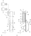
[0008] 도 1의 (a)는, 본 발명의 제1 실시형태에 따른 두부류 제조 장치를 나타낸 개략 상면도이고, (b)는, (a)의 개략 측면도이다.
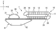
도 2는, 본 발명의 제1 실시형태의 제1 변형예에 따른 두부류 제조 장치를 나타낸 개략 측면도이다.
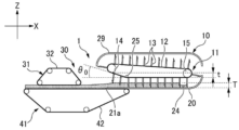
도 3은, 본 발명의 제1 실시형태의 제2 변형예에 따른 두부류 제조 장치를 나타낸 개략 측면도이다.
도 4는, 본 발명의 제1 실시형태의 제3 변형예에 따른 두부류 제조 장치를 나타낸 개략 측면도이다.
도 5는, 본 발명의 제1 실시형태의 제4 변형예에 따른 두부류 제조 장치를 나타낸 개략 측면도이다.
도 6은, 본 발명의 제1 실시형태의 제5 변형예에 따른 두부류 제조 장치를 나타낸 개략 측면도이다.
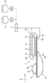
도 7은, 본 발명의 제1 실시형태의 제6 변형예에 따른 두부류 제조 장치를 나타낸 개략 측면도이다.
도 8의 (a)는, 본 발명의 제1 실시형태의 제7 변형예의 일례에 따른 두부류 제조 장치를 나타낸, 도 1의 VIII-VIII에 대응하는 개략 측면도이고, (b)는, 본 발명의 제1 실시형태의 제7 변형예의 다른 예에 따른 두부류 제조 장치를 나타낸, 도 1의 VIII-VIII에 대응하는 개략 측면도이다.
도 9의 (a)는, 본 발명의 제2 실시형태에 따른 두부류 제조 장치를 나타낸 개략 상면도이고, (b)는, (a)의 개략 측면도이다.
도 10은, 도 9의 연속 응고기의 입구 부근의 단면도이며, (a)는, 공급구가 닫혀 있는 상태를 나타내고, (b)는, 공급구가 열려 있는 상태를 나타낸다.
도 11은, 본 발명의 제2 실시형태의 제1 변형예에 따른 두부류 제조 장치에 있어서, 연속 응고기의 입구 부근의 단면도이며, (a)는, 공급구가 닫혀 있는 상태를 나타내고, (b)는, 공급구가 열려 있는 상태를 나타낸다.
도 12는, 본 발명의 제2 실시형태의 제2 변형예에 따른 두부류 제조 장치에 있어서, 연속 응고기의 입구 부근의 단면도이며, (a)는, 공급구가 닫혀 있는 상태를 나타내고, (b)는, 공급구가 열려 있는 상태를 나타낸다.
도 13은, 본 발명의 제2 실시형태의 제3 변형예에 따른 두부류 제조 장치에 있어서, 연속 응고기의 응고조의 이송 부분을 상면에서 본 개략도이다.
도 14는, 본 발명의 제2 실시형태의 제4 변형예에 따른 두부류 제조 장치에 있어서, 연속 응고기의 응고조의 개략 측면도이다.
도 15는, 본 발명의 제2 실시형태의 제4 변형예에 따른 두부류 제조 장치에 있어서, 응고제 함유 두유를 전환 삼방 밸브를 이용하여 연속 응고기에 공급하는 과정을 나타낸, 연속 응고기의 응고조의 이송 부분을 위에서 본 개략도이다.
도 16의 (a)는, 본 발명의 제3 실시형태에 따른 두부류 제조 장치를 나타낸 개략 상면도이고, (b)는, (a)의 개략 측면도이고, (c)는, (b)의 XV부 확대도이다.
도 17의 (a)는, 본 발명의 제3 실시형태의 변형예에 따른 두부류 제조 장치에 있어서, 도 16의 (b)의 XV부에 대응하는 도면이고, (b)는, 본 발명의 제3 실시형태의 다른 변형예에 따른 두부류 제조 장치에 있어서, 도 16의 (b)의 XV부에 대응하는 도면이다.1 (a) is a schematic top view showing a tofu manufacturing apparatus according to a first embodiment of the present invention, and (b) is a schematic side view of (a).
Fig. 2 is a schematic side view showing a tofu production device according to a first modified example of the first embodiment of the present invention.
Fig. 3 is a schematic side view showing a tofu production device according to a second modified example of the first embodiment of the present invention.
Fig. 4 is a schematic side view showing a tofu production device according to a third modified example of the first embodiment of the present invention.
Fig. 5 is a schematic side view showing a tofu production device according to a fourth modified example of the first embodiment of the present invention.
Fig. 6 is a schematic side view showing a tofu production device according to a fifth modified example of the first embodiment of the present invention.
Fig. 7 is a schematic side view showing a tofu production device according to a sixth modified example of the first embodiment of the present invention.
8 (a) is a schematic side view corresponding to VIII-VIII in FIG. 1 showing a tofu production device according to an example of a seventh modification of the first embodiment of the present invention, and (b) is a schematic side view of the present invention It is a schematic side view corresponding to VIII-VIII in FIG. 1 showing a tofu production device according to another example of the seventh modification of the first embodiment.
Fig. 9 (a) is a schematic top view showing a tofu production device according to a second embodiment of the present invention, and (b) is a schematic side view of (a).
Fig. 10 is a cross-sectional view of the inlet vicinity of the continuous coagulator of Fig. 9, (a) shows a state in which the supply port is closed, and (b) shows a state in which the supply port is open.
11 is a cross-sectional view of the vicinity of the inlet of the continuous coagulator in the tofu production device according to the first modified example of the second embodiment of the present invention, (a) shows a state in which the supply port is closed, (b ) indicates a state in which the supply port is open.
12 is a cross-sectional view of the vicinity of the inlet of the continuous coagulator in the tofu production device according to the second modification of the second embodiment of the present invention, (a) shows a state in which the supply port is closed, (b ) indicates a state in which the supply port is open.
Fig. 13 is a schematic view of the transfer portion of the coagulation tank of the continuous coagulant in the tofu production device according to the third modified example of the second embodiment of the present invention, viewed from the top.
Fig. 14 is a schematic side view of the coagulation tank of the continuous coagulator in the tofu production device according to the fourth modified example of the second embodiment of the present invention.
15 is a transfer of the coagulation tank of the continuous coagulator showing a process of supplying soymilk containing a coagulant to the continuous coagulator using a switching three-way valve in the tofu production apparatus according to the fourth modified example of the second embodiment of the present invention. This is a schematic view of the part from above.
16 (a) is a schematic top view showing a tofu production device according to a third embodiment of the present invention, (b) is a schematic side view of (a), (c) is XV of (b) It is an enlarged view.
17(a) is a view corresponding to XV of FIG. 16(b) in the tofu manufacturing apparatus according to a modification of the third embodiment of the present invention, and (b) is a view corresponding to the first part of the present invention. In the tofu production device according to another modification of the third embodiment, it is a view corresponding to part XV of FIG. 16(b).
[0009] 이하에서는, 본 발명의 각 실시형태에 따른 두부류 제조 장치 및 두부류 제조 방법에 대해, 도면을 참조하여 상세히 설명한다.[0009] Hereinafter, tofu manufacturing apparatus and tofu manufacturing method according to each embodiment of the present invention will be described in detail with reference to the drawings.
[0010] (제1 실시형태)[0010] (First Embodiment)
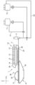
도 1에 나타낸 바와 같이, 제1 실시형태의 두부류 제조 장치(1)는, 두유와 응고제가 믹서(2)에 의해 혼합된 응고제 함유 두유를 응고·숙성하여, 푸딩 형상의 두유 응고물을 생성하는 배 형상의 연속 응고기(10)와, 두유 응고물을 탈수하면서 두부류로 성형하는 연속 성형기(30)를 구비한다.As shown in Fig. 1, the tofu production device 1 of the first embodiment coagulates and ages coagulant-containing soymilk in which soymilk and coagulant are mixed by a
두유와 응고제는, 저류(貯留)되는 두유 탱크(T1) 및 응고제 탱크(T2)로부터, 정량 펌프(P1, P2)에 의해 소정의 유량으로 송액(送液)되고, 믹서(2)로 혼합되어, 응고제 함유 두유로서 연속 응고기(10)에 공급된다. 또한, 연속 응고기(10)에는, 두유, 응고제가 따로따로 직접 공급되어 응고조(20) 내에서 혼합되어도 된다. 어느 쪽이든, 대부분(하나의 구획의 응고제 함유 두유의 50% 이상)이 액면 아래에 공급되는 것이 바람직하다.The soy milk and the coagulant are fed from the soy milk tank T1 and the coagulant tank T2 stored at a predetermined flow rate by the metering pumps P1 and P2, and mixed by the
[0011] 또한, 본 실시형태의 두부류 제조 장치(1)는, 연속 응고기(10)에 있어서의 응고제 함유 두유의 이송 방향과 연속 성형기(30)에 있어서의 두유 응고물의 이송 방향이 동일한 방향이 되도록, 연속 응고기(10)와 연속 성형기(30)가 직선형으로 나란히 배치되어 있다. 설치 공간(space)은 넓어지지만, 부드러운 대략 푸딩 형상의 응고물을 별로 부서뜨리지 않고 정량적으로 갈아타게 할 수 있다. 여기서는, 연속 응고기(10)와 연속 성형기(30)가 나란한 수평 방향을 X방향으로 하고, X방향과 직교하는 수평 방향인, 연속 응고기(10) 및 연속 성형기(30)의 폭방향을 Y방향으로 하고, 연속 응고기(10) 및 연속 성형기(30)의 상하 방향을 Z방향으로 한다.In addition, in the tofu production device 1 of the present embodiment, the conveying direction of the coagulant-containing soymilk in the
[0012] 배 형상의 연속 응고기(10)는 컨베이어 벨트(무단 체인)(12)의 표면에 소정의 간격으로 복수의 분할 블레이드(13)가 부착된 무단 형상 컨베이어(11)와, 분할 블레이드(13)가 내부를 통과하는, 단면이 오목한 형상인 스테인리스제의 응고조(20)와, 무단 형상 컨베이어(11)의 상방을 덮는 커버(29)를 주로 갖는다.[0012] The pear-shaped
[0013] 무단 형상 컨베이어(11)는, 응고조(20)의 입구 부근과 출구 부근에, 대략 수평으로 나란히 배치되는 2개의 롤러(14, 15) 둘레에 컨베이어 벨트(무단 체인)(12)를 걸치고, 2개의 롤러(14, 15)의 회전에 의해 컨베이어 벨트(무단 체인)(12) 및 복수의 분할 블레이드(13)를 주회(周回)시킨다.[0013] The
[0014] 연속 응고기(10)의 컨베이어 벨트(무단 체인)(12)는, 스틸 벨트, 스테인리스나 티타늄 등의 강성이 있는 금속제 벨트나 체인이나 와이어이며, 분할 블레이드를 다수 고정할 수 있는 것이면 특별히 한정되지 않는다.[0014] The conveyor belt (endless chain) 12 of the
[0015] 복수의 분할 블레이드(13)는, 스테인리스나 티타늄 등의 금속강제 판부재(13)와 고무제 부재(13b)로 이루어지며, 폭방향으로 길고 종방향으로 짧은 직사각형상을 갖고 있고, 두유나 「웃물」 등의 액(液)이 새지 않도록 유연한 NBR이나 EPDM, FKM 등의 (불소 고무), 실리콘 고무 등의 고무제 시일(seal) 부재(13b)로 응고조(20)의 바닥벽(底壁)(21) 및 양 측벽(22, 23)의 내면과 내접(內接) 또는 접촉하는 크기를 갖는다. 따라서, 연속 응고기(10)는, 서로 이웃하는 분할 블레이드(13)와 응고조(20)에 의해 응고 구획을 형성한다.[0015] The plurality of
[0016] 응고조(20)의 바닥벽(21)은, 응고제 함유 두유를 공급하는 입구 부근에 있어서는, 분할 블레이드(13)의 선단의 궤도에 맞춰 만곡되어 있는 한편, 출구단부(21a)로부터 입구 부근을 향해 만곡 부분까지 대략 수평으로 형성되어 있다.[0016] The
[0017] 또한, 응고조(20)의 입구 부근의 측벽(22, 23) 중 적어도 한쪽에는, 응고제 함유 두유를 공급하기 위한 공급구(24)가 설치되어 있다. 따라서, 공급구(24)로부터 공급된 응고제 함유 두유는, 분할 블레이드(13)가 연속 응고기(10)의 출구 부근을 향해 이동함으로써, 응고·숙성된다. 또한, 공급구에는, 후술하는 제2 실시형태의 개폐 부재가 설치되어도 된다.In addition, at least one of the
[0018] 또한, 커버(29)는, 리턴 부분에 위치하는 복수의 분할 블레이드(13) 전체의 상방을 덮도록, 분할 블레이드(13)의 선단의 궤도에 맞춰 형성되어 있다. 이에 의해, 생산 중에, 공기 중의 낙하균으로 인한 이차 오염을 방지하는 동시에, 응고 숙성 공정에서의 보온성을 높일 수 있다.[0018] The
[0019] 연속 성형기(30)는, 상측 포(32)가 감기는 상측의 무단 형상 반송 컨베이어(31)와, 하측 포(42)가 감기는 하측의 무단 형상 반송 컨베이어(41)를 갖는다. 아래를 향하는 상측 포(32)의 표면과, 위를 향하는 하측 포(42)의 표면은, 각각 대략 수평하며, 간극을 갖고 대향한다.[0019] The continuous forming
[0020] 상측의 무단 형상 반송 컨베이어(31)와 하측의 무단 형상 반송 컨베이어(41)의 각 롤러의 중심축은, 무단 형상 컨베이어(11)의 2개의 롤러(14, 15)의 중심축과 서로 평행하게 배치되어 있다.[0020] The central axis of each roller of the upper
[0021] 또한, 상측 포(32)나 하측 포(42)는, 유연성과 강인성이 있고, 불소 수지나 폴리에스테르 수지, 폴리프로필렌 수지, 폴리에틸렌 수지 등의 모노필라멘트가 평직, 능직 등으로 짜여진 수지제 여과포(예컨대 일본 특허 제4004413호 등 참조)로서, 시작단(始端)이나 후단(後端)에서는 평권 형상(平捲狀)이며, 반송면으로 바닥면(底面)과 측벽을 형성하는 수지제 여과포 벨트 스테인리스 등의 금속제 와이어를 짜넣은 와이어 네트 벨트(아이 링크 벨트 컨베이어(eye link belt conveyor), 플랫 플렉스 컨베이어(flat flex conveyor), 초콜릿 컨베이어(chocolate conveyor) 등)이고, 유공(有孔) 내지 무공(無孔)의 식품용 수지 벨트(테플론 벨트나 식품용 벨트)이면 된다.[0021] The
[0022] 상측의 무단 형상 반송 컨베이어(31)와 하측의 무단 형상 반송 컨베이어(41)는, 두유 응고물을 위아래에서 끼워서 프레스하여, 탈수하면서 두부류를 성형하고, 하류 공정으로 반송한다.[0022] The upper
[0023] 여기서, 하측의 무단 형상 반송 컨베이어(41)는, 하측 포(42)가 응고조(20)의 바닥벽(21)의 출구단부(21a)의 하방에 위치하도록, 상방에서 볼 때 응고조(20)와 오버랩되어 있다. 즉, 하측의 무단 형상 반송 컨베이어(41)는, 응고조(20)의 하방에 근접하여 위치하도록, 상측의 무단 형상 반송 컨베이어(31)보다 연속 응고기측으로 연장되어 구성된다.[0023] Here, the lower
[0024] 또한, 응고조(20)와 상측의 무단 형상 반송 컨베이어(41)는, 하측의 무단 형상 반송 컨베이어(41)의 하측 포(42)의 상방에서, X방향으로 직선형으로 나란히 배치되어 있다.Further, the
[0025] 또한, 연속 응고기(10)는, 연속 성형기(30)와 동기하여 구동된다. 즉, 연속 응고기(10)의 무단 형상 컨베이어(11)의 컨베이어 벨트(무단 체인)(12)와, 연속 성형기(30)의 상측의 무단 형상 반송 컨베이어(31)의 상측 포(32)와, 하측의 무단 형상 반송 컨베이어(41)의 하측 포(42)는, 각각의 이송 부분에 있어서 동일한 속도로 동일한 방향으로 연속 구동된다.In addition, the
[0026] 이에 의해, 응고조(20)의 바닥벽(21)의 출구단부(21a)와 하측의 무단 형상 반송 컨베이어(41)의 하측 포(42)는 낙차가 작은 상태가 되어, 두유 응고물은, 분배기나 투입기를 통하지 않고, 연속 응고기(10)로부터 반출(搬出)되는 푸딩 형상의 두유 응고물의 관성력을 그대로, 직접 하측 포(42)로 옮길 수 있다. 또한, 분할 블레이드(13)에 의해 나누어진 응고 구획에 의해, 정량성을 확보하면서, 두유 응고물을 하측 포(42) 상에 이재(移載; 옮겨 싣기)할 수 있다.[0026] As a result, the
[0027] 종래와 같은, 성형기의 상방에 응고기가 배치되는 2층 구조에서는, 두유 응고물은 낙차로 인해 반드시 깨진 상태가 되고, 또한, 응고조의 출구에서는 구획된 구분마다 두부가 단번에 흘러나오기 때문에, 응고기의 무단 형상 컨베이어는 단속(斷續) 운전이고, 성형기도 그에 맞춰 단속 운전하는 것이 통상적이었다. 또한, 응고기와 성형기를 연속 운전한 경우에는, 두유 응고물을 담는 것이 불균일해지기 쉬웠다.[0027] In the conventional two-layer structure in which a coagulator is disposed above the molding machine, the soybean milk coagulum is always broken due to a drop, and tofu flows out at once in each partitioned section at the exit of the coagulation tank, It was common for the endless shape conveyor of the coagulator to operate intermittently, and the molding machine to operate intermittently accordingly. In addition, when the coagulator and the molding machine were continuously operated, the soymilk coagulum was likely to be non-uniform.
한편, 본 실시형태의 두부류 제조 장치(1)는, 1층 구조의 지상 배열로 직선적이므로, 두유 응고물이 단번에 흘러나오는 것이 억제되어, 부드러운 푸딩 형상의 두유 응고물을 부서뜨리지 않고, 낙차 없이 그대로 부드럽게 하측 포(42) 상에 이재할 수 있다. 또한, 두부류 제조 장치(1)의 메인터넌스 시 등에, 고소(高所)에서의 작업이 줄어들어, 작업 안전성도 높아진다.On the other hand, since the tofu production device 1 of the present embodiment is linear with a one-layer structure above ground, soybean milk curdled substance is prevented from spilling out at once, and the soft pudding-shaped soymilk curdled substance is not broken, and there is no drop. It can be transferred on the
[0028] 예컨대, 파단력이 60gf/cm2 이상인 약간 단단한 푸딩 형상의 두유 응고물이라면, 스틸 벨트를 이용한 응고기(일본 특허 제3568193호)를 적용할 수 있지만, 파단력이 60gf/cm2 미만, 구체적으로는, 1~40gf/cm2 정도, 특히, 5~20gf/cm2 정도인 매우 부드러운 푸딩 형상의 두유 응고물인 경우, 미끄러지거나, 갈라져서, 제대로 반송할 수 없다. 한편, 본 실시형태의 연속 응고기(10)를 이용함으로써, 상기 파단력이 작은 매우 부드러운 푸딩 형상의 두유 응고물이더라도 거의 부서뜨리지 않고 반송, 갈아타기를 하게 할 수 있다.[0028] For example, if the soymilk coagulum has a slightly hard pudding shape with a breaking force of 60 gf/cm 2 or more, a coagulator using a steel belt (Japanese Patent No. 3568193) can be applied, but the breaking force is less than 60 gf/cm 2 , Specifically, in the case of very soft pudding-shaped soymilk coagulum of about 1 to 40 gf/cm 2 , particularly about 5 to 20 gf/cm 2 , it slips or cracks and cannot be conveyed properly. On the other hand, by using the
[0029] 또한, 연속 응고기(10)는, 연속 성형기(30)와 낙차가 적으며, 또한 동기 및 동일 속도로 구동됨으로써, 매우 부드러운 푸딩 형상의 두유 응고물을 그대로 부서뜨리지 않고, 균등하게 연속 성형기(30)의 하측 포(42) 상에 이재하는 것이 가능해진다.[0029] In addition, the
연속 응고기(10)와 연속 성형기(30)는, 단속 운전(배치식(batch type))하는 것보다, 기계의 부담이 적고, 구동 모터의 기동 전류치도 적어서 에너지 절약이 된다. 또한, 배치식 구동에 비해, 장기간 사용으로 인해 체인이 늘어나는 것 등에 의한 타이밍의 어긋남의 영향도 적다.The
[0030] 또한, 연속 응고기(10)의 응고조(20)의 폭 A는, 연속 성형기(30)의 프레스부(상측 포(32)의 Y방향 폭)의 폭 B와 거의 동일하다. 구체적으로, 응고조(20)의 폭 A는, 프레스부의 폭 B에 대해, 80%~100%, 바람직하게는 90%~100%이다. 실제 사이즈에서는, 프레스부의 폭 B는 500~3,000mm(대체로 1,000~2,000mm)이다.In addition, the width A of the
종래의 유부 생지 성형기에서는, 순두부 형상(두유 응고물과 황록색의 「웃물」이 혼합된 응고 상태)의 응고 상태이며, 배 형상의 응고기의 응고조의 폭은, 성형기의 성형 폭보다 좁은 것이 일반적이기 때문에, 분배기(투입기)에 의해 성형기 폭으로 넓혀 균등하게 분배된다.In the conventional tofu dough forming machine, it is in a solidified state in the form of soft tofu (a solidified state in which soymilk coagulum and yellow-green “sweet water” are mixed), and the width of the pear-shaped coagulation tank is generally narrower than the molding width of the molding machine. Therefore, it is spread evenly across the width of the molding machine by the distributor (injector).
한편, 본 실시형태에서는, 연속 응고기(10)의 응고조(20)의 폭 A는, 연속 성형기(30)의 프레스부의 폭 B와 거의 동일하므로, 연속 응고기(10)와 연속 성형기(30) 사이에서 두유 응고물을 전달할 때, 응고기(10)로부터 반출되어 오는 매우 부드러운 대략 푸딩 형상으로 응고된 두유 응고물을, 부서뜨리지 않고 그대로 직접(분배기 등을 통하지 않고) 성형기(30)의 하측 포(42) 상에 부드럽게 내려놓는(soft landing) 것이 가능하다.On the other hand, in the present embodiment, since the width A of the
[0031] 또한, 응고조(20)의 바닥벽(21)은, 입구 부근으로부터 출구단부(21a)를 향해 대략 수평으로 형성되므로, 낙차가 없어, 약간 유리(遊離)되는 물(이른바 「웃물」, 「이수」 「청수(淸水)」라고도 함)의 치우침을 방지하는 동시에, 부드러운 대략 푸딩 형상의 두유 응고물과 함께 스무스하게 반송하여, 성형기로 갈아탈 때 중력의 영향에 의한 미끄럼대와 같은 현상을 방지할 수 있다.[0031] In addition, since the
[0032] <변형예>[0032] <Modification>
또한, 상기 실시형태에서는, 응고조(20)의 바닥벽(21)과 하측 포(42) 사이에 간극을 갖는 구성으로 하였으나, 도 2에 나타낸 제1 변형예와 같이, 응고조(20)의 출구단부(21a)를 포함하는 바닥벽(21)이 하측 포(42)에 거의 접하도록 구성되어도 된다.In the above embodiment, a gap is provided between the
이에 의해, 응고조(20)의 바닥벽(21)의 출구단부(21a)와 하측의 무단 형상 반송 컨베이어(41)의 하측 포(42)는 낙차가 더 작은 상태가 되어, 두부 응고물을 보다 확실히 부서뜨리지 않고 하측 포(42) 상에 이재할 수 있다.As a result, the
[0033] 또한, 상기 실시형태에서는, 연속 응고기(10)의 무단 형상 컨베이어(11)는, 복수의 분할 블레이드(13)의 선단 내지 부착단이, 이송 방향에 있어서, 수평으로 이동하도록 구성하였지만, 도 3에 나타낸 제2 변형예와 같이, 응고조(20)의 출구 부근에 있어서, 상승하며 이동하도록 구성되어도 된다. 즉, 무단 형상 컨베이어(11)의 컨베이어 벨트(무단 체인)(12)는, 분할 블레이드(13)의 선단 내지 부착단이 점차, 상방으로 올라가도록, 연속 응고기(10)의 이송 방향을 향해 상방으로 각도 θ0만큼 경사시킨다(0°≤θ0≤30°의 범위). 구체적으로는, 컨베이어 벨트(무단 체인)(12)를 이송측으로부터 리턴측으로 회전하며 안내하는 롤러(14)의 롤러(15)에 대한 높이 t가 두유 응고물의 높이 T 이상이 되도록 조정하는 것이 바람직하다. 이를 위해, 출구측의 롤러(14)를 입구측의 롤러(15)보다 높게 배치하여, 컨베이어 벨트(무단 체인)(12)는, 가이드 롤러(25)를 통과한 후, 분할 블레이드(13)와 함께 상승하며, 분할 블레이드(13)가 하측 포(42)로부터 서서히 이격되도록 구성된다.[0033] In the above embodiment, the
[0034] 분할 블레이드(13)의 선단이, 출구 부근에 있어서, 이송 방향에 있어서 수평으로 이동하는 경우, 분할 블레이드(13)는, 이송 부분으로부터 리턴 부분으로 반전할 때, 두유 응고물의 상단(上端)을 차올려서, 다소 부서뜨려 버릴 가능성이 있다.[0034] When the front end of the
[0035] 한편, 이 변형예와 같이, 분할 블레이드(13)를, 출구 부근에 있어서, 상방으로 이동시킴으로써, 두유 응고물의 상단을 차올리는 일이 없어져, 두유 응고물이 부서지는 것을 확실히 방지할 수 있다. 또한, 응고 숙성 중, 인접한 분할 블레이드(13) 사이(각 응고 구획)에 고인 이수를 보다 빨리 제거할 수도 있다.[0035] On the other hand, as in this modification, by moving the
또한, 무단 형상 컨베이어(11)는, 컨베이어 벨트(무단 체인)(12)의 경사를 임의로 조정할 수 있도록 구성되어도 된다.Further, the
[0036] 또한, 상기 실시형태에서는, 연속 응고기(10)는, 응고조(20)의 입구 부근에 있어서, 응고조(20)의 측벽(22)에 응고제 함유 두유를 공급하는 공급구(24)를 설치하고 있지만, 도 4에 나타낸 제3 변형예와 같이, 공급구(24)는, 응고조(20)의 바닥벽(21)에 설치되어도 된다.Further, in the above embodiment, the
또한, 어느 형태에 있어서나, 공급구(24)는, 액면 레벨보다 아래에서 응고제 함유 두유를 유입시키는 것이 기포 발생이나 기포 혼입을 억제하는 데 있어서 바람직하다. 액면 레벨이란, 응고 구획 내에 공급되는 응고제 함유 두유의 양이 가장 적은 두부류의 경우를 상정하여 설정된다.In either mode, it is preferable to introduce coagulant-containing soymilk below the liquid surface level through the
[0037] 예컨대, 응고기(10)의 입구측의 상방에서 두유와 응고제를 흘려 넣는 경우, 주회하는 분할 블레이드(13)에 간섭하지 않도록 일정한 거리로 공급구(24)를 설치하기 때문에, 기포 발생이나 유입의 힘으로 응고물에 기포가 섞여, 응고가 불균일해지기 쉬웠다. 또한 응고 구획의 공간이 안정되지 않아, 응고 편차도 생기기 쉬웠다. 특히, 무(無)소포제 두유에서는 기포가 매우 쉽게 발생하여, 현저한 기포의 혼입이 일어났다. [0037] For example, when soybean milk and coagulant are poured from above the inlet side of the
한편, 상기 실시형태나 제3 변형예에서는, 응고 구획의 공간의 형상이 고정된(직육면체 형상) 상태이며, 공급구(24)로부터 응고제 함유 두유를 흘려 넣을 때, 대부분은 액면 근처 내지는 액중(液中)에 흘려 넣으므로, 기포 발생은 적고, 기포의 혼입이 적은, 균질한 푸딩 형상의 두유 응고물이 안정적으로 얻어지기 쉽다. 분할판이 리턴측으로부터 이송측으로 회전하는 위치에서는 응고 구획 형상이 변화하기 때문에, 회전하는 위치를 지나 앞뒤의 분할판으로 구획되고 그 후 변화 없이 고정된 응고 구획이 형성된 곳에서, 응고제 함유 두유를 투입하는 것이 수분보유성(保水性)이 높은 응고 상태를 안정적으로 얻을 수 있다.On the other hand, in the above embodiment and the third modified example, the shape of the space of the coagulation compartment is fixed (rectangular parallelepiped shape), and when the coagulant-containing soymilk is poured from the
[0038] 또한, 공급구(24)는, 본 실시형태의 측벽 한 군데나, 제3 변형예의 바닥벽 한 군데에 한정되지 않고, 양 측벽의 두 군데, 바닥벽에 복수 군데, 양 측벽과 바닥벽의 세 군데 등, 적절히 설계되면 된다.[0038] In addition, the
[0039] 또한, 도 5에 나타낸 제4 변형예와 같이, 연속 응고기(10)는, 커버(29)의 상방에, 리턴 부분에 위치하는 분할 블레이드(13)를 세정하는 세정부(26)나, 커버(29) 내에 증기를 공급하는 증기 공급 장치(27)를 더 구비해도 된다. 세정부(26)의 하방에서, 리턴 부분에 위치하는 분할 블레이드(13)나 컨베이어 벨트(무단 체인)(12)의 하측에 세정액을 받는 받침 접시(28)를 설치해도 되며, 비생산 시 외에, 생산 시에도 주회할 때마다 세정할 수 있고, 장시간 생산 시에도 위생적인 환경을 유지할 수 있다. [0039] In addition, as in the fourth modified example shown in FIG. 5, the
또한, 세정할 때에는, 공급구(24)는, 응고제 함유 두유나 세정약액을 배출하는 배출구로 해도 되고, 혹은, 배출구를 응고조(20)의 입구 부근에 별도로 설치해도 된다.In the case of washing, the
[0040] 증기 공급 장치(27)에 의해 증기를 커버(29) 내에 공급함으로써, 두유 응고물을 소정 온도로 보온할 수 있다. 두유 응고물로부터 발생하는 김과 함께, 포화 증기에 의해 60~100℃로 커버(29) 내의 공간을 유지함으로써, 잡균의 번식을 방지하여, 위생적으로 두유 응고물을 반송할 수 있다.[0040] By supplying steam into the
[0041] 또한, 세정부(26)에 의해, 약액(藥液)에 의한 CIP(Cleaning in place) 세정이나, 증기 또는 열수(熱水)나 약액에 의한 살균을 행하는 것이 가능하다. 배 형상의 연속 응고기(10)는 분할 블레이드(13)가 주회하기 때문에, 분할 블레이드(13)(스테인리스강이나 고무 주걱으로 이루어진 부품)에 부착되는 두부박이 장시간 경과하면 비위생적이 되므로, 생산 중에는 분할 블레이드(13)의 주회 궤도의 리턴 부분에서 고압 세정 노즐을 구비한 세정부(26)를 설치하여 두부박을 씻어낸다.[0041] Further, the
[0042] 또한, 생산 후 세정 시에는, 응고조(20)에 세정약액을 약간 깊게(생산 시의 두유 응고물 레벨 이상, 만액(滿液)이 바람직함) 담고, 분할 블레이드(13)를 주회시키는 침지 세정도 병용한다. 응고조(20)의 출구단부(21a)에서 배출된 세정약액은 필터로 고형물 제거 후, 두유 탱크 내지는 세정약액 탱크로 되돌린다. 헹굼세탁된 배액은 되돌리지 않고, 배수한다. 또한, 커버(29) 내에 약액을 살포할 수 있는 액체살포(散液) 노즐(회전식 스프레이 노즐이나 스프레이 볼 등)을 설치하여, 커버(29) 안이나 응고조(20)나 분할 블레이드(13)를 CIP 세정하도록 해도 된다.[0042] In addition, at the time of washing after production, the washing liquid is slightly deep in the coagulation tank 20 (above the level of soymilk coagulum at the time of production, full liquid is preferable), and the
[0043] 또한, 응고조(20)는, 이중 구조 내지는 보온 수단을 설치해도 된다. 응고조(20)는 일반적으로 스테인리스강으로 이루어지지만, 한겹 구조에서는 방열(放熱)이 커서, 측벽이나 바닥벽 부근의 두부의 질이 약간 부드러워진다. 이것이 이후의 성형기(30)에서 포(布)에 들러붙어 버리는 트러블이 될 가능성이 있다. 이중 구조로 공기층을 설치하거나, 단열재를 넣거나, 진공층으로 하거나, 뜨거운 물 또는 수증기 또는 열매체(熱媒)를 순환 온도 조절(溫調)하는, 등의 보온 수단을 설치함으로써, 숙성 후의 두부는 측벽 근처에서나 바닥벽 근처에서나, 중심부의 두부의 품질과 다르지 않게 되어, 전체적으로 결착성(結着)이 좋고, 탄력이 있는, 부드러운 푸딩 형상 두부가 만들어져서, 로스(loss)도 경감된다. 또한 분할 블레이드(13)에 부착되는 두부박의 양도 줄일 수 있다. 불필요한 응고제나 세정수를 사용하지 않아, 절약도 된다.[0043] In addition, the
[0044] 또한, 상기 실시형태에서는, 분할 블레이드(13)는, 이송 부분에 있어서의 수평한 컨베이어 벨트에 대해, θ=90°로 부착되어 있지만, 응고조(20)의 바닥벽(21)과 측벽(22, 23)에 근접 또는 접촉하는 구성이라면, 소정의 각도 θ로 경사지게 부착되어도 된다.[0044] In the above embodiment, the
[0045] 구체적으로는, 분할 블레이드(13)는, 45°≤θ≤150°의 범위로, 바람직하게는 60°≤θ≤90°로, 컨베이어 벨트(무단 체인)(12)의 표면에 부착되면 된다. 특히, 도 6에 나타낸 제5 변형예와 같이, 이송 부분에 있어서, 분할 블레이드(13)의 선단이 기단(基端)에 대해 입구쪽을 향하도록, 45°≤θ<90° 내지는 60°≤θ<90°로 경사지게 부착되어도 되고, 이에 의해, 출구 부근에 있어서, 두유 응고물의 상부를 차올리는 것을 줄일 수 있다.[0045] Specifically, the
[0046] 또한, 도 7에 나타낸 제6 변형예에서는, 두유 탱크(T1) 및 응고제 탱크(T2)로부터, 두유와 응고제를 정량 펌프(P1, P2)에 의해 소정의 유량으로 송액하고, 믹서(2)로 혼합한 응고제 함유 두유를 응고조(20)에 공급하고 있는데, 정량 펌프(P1, P2)와 믹서(2) 사이에 밸브(V1, V2)를 설치하고, 두유를 두유 탱크(T1)로, 응고제를 응고제 탱크(T2)로 각각 되돌리는 순환로(C1, C2)를 설치하고 있다. 이 경우, 응고제 함유 두유는 연속식 공급이어도 되고, 배치식 공급이어도 된다.[0046] Further, in the sixth modification shown in FIG. 7, the soybean milk and the coagulant are fed at a predetermined flow rate from the soy milk tank T1 and the coagulant tank T2 by the metering pumps P1 and P2, and the mixer ( The coagulant-containing soymilk mixed in 2) is supplied to the
[0047] 예컨대, 응고제 함유 두유의 연속식 공급인 경우, 두유와 응고제의 전환 밸브(V1, V2)가 생산측으로 전환된 상태로, 각각 계속 소정 유량으로 흐르게 하고, 응고조(20)의 분할 블레이드(13)는 연속으로 구동된다. 이 경우, 분할 블레이드(13)의 배치식의 구동은 불가능하다.[0047] For example, in the case of continuous supply of coagulant-containing soymilk, the switching valves V1 and V2 of the soymilk and the coagulant are switched to the production side, and each continues to flow at a predetermined flow rate, and the divided blades of the coagulation tank 20 (13) is continuously driven. In this case, batchwise driving of the
[0048] 한편, 응고제 함유 두유의 배치식 공급인 경우, 분할 블레이드(13)가 소정 위치에 온 시점에, 두유와 응고제의 전환 밸브(V1, V2)가 순환측에서 생산측으로 전환되어, 믹서(2)로 혼합한 응고제 함유 두유를 응고조(20)에 공급하는 것을 개시한다. 소정량의 공급이 종료되면, 전환 밸브(V1, V2)가 순환측으로 전환되어, 공급을 정지한다. 그 동안, 분할 블레이드(13)는 연속으로 구동되고 있어도 되고, 혹은, 분할 블레이드(13)는, 공급 정지 후에 배치(batch)로 구동되어 다음 분할 블레이드(13)가 소정 위치에 온다. 따라서, 분할 블레이드(13)는, 기본 연속 구동이 바람직하지만, 배치식인 구동이어도 된다.On the other hand, in the case of batch supply of coagulant-containing soymilk, when the
[0049] 공급 정지 시, 이른바 「에지 차단(端切)」(일본 특허공개 H11-346696호 참조)을 행하는 것이 바람직하다. 에지 차단이란, 두유 전환 밸브(V1)와 응고제 전환 밸브(V2)가 생산측에서 순환측으로 전환될 때, 밸브(V2)의 전환을 보다 빨리 행하여, 밸브(V1)~믹서(2)~공급구(24)에 두유만을 충만시켜 대기시킨다. 이에 의해, 두유 응고물이 믹서(2)나 믹서(2)의 앞뒤에 쌓이는 것을 방지하고, 응고가 깨진 두부가 혼합되어 품질을 떨어뜨리는 것을 방지한다. 두유분(分)은 다음 배치(batch)로 공급되는데, 응고제 함유 두유와 섞여, 품질상의 문제는 없다. 이와 같이 마지막 단시간에는 응고제를 넣지 않는 부분을 만드는 것, 밸브(V1)의 타이밍을 늦추는 것을 「에지 차단」이라고 한다.[0049] When supply is stopped, it is preferable to perform so-called "edge blocking" (refer to Japanese Unexamined Patent Publication No. H11-346696). Edge blocking means that when the soymilk switching valve V1 and the coagulant switching valve V2 are switched from the production side to the circulation side, the valve V2 is switched more quickly, so that the valve V1 - mixer 2 - supply port (24) is filled with only soymilk and left to stand by. This prevents soybean milk coagulum from accumulating in the
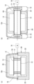
[0050] 또한, 도 8의 (a) 및 도 8의 (b)에 나타낸 제7 변형예와 같이, 무단 형상 컨베이어(11)에서는, 컨베이어 벨트(12)를 그 폭방향 양측에서 연결하는 한 쌍의 무단 체인(71, 71)이 스프로킷(70, 70)에 걸쳐져 있다. 그리고, 스프로킷(70, 70)이, 구동부(74)에 의해 구동축(75)을 회전시킴으로써, 무단 체인(71, 71)과 함께 컨베이어 벨트(12)가 구동된다. 컨베이어 벨트(12)는, 무단 체인(71, 71)에 연결된 복수의 금속 플레이트에 의해 구성되며, 이들 금속 플레이트의 표면에 분할 블레이드(13)가 부착되어 있다.[0050] Further, as in the seventh modified example shown in FIGS. 8A and 8B, in the
또한, 금속 플레이트는, 평판 형상뿐만 아니라, 앵글 형상, 원형봉 형상이어도 되고, H형 강이나 C형 강 등이 적용되어도 된다. 금속 플레이트의 재질도, 스테인리스에 한정되지 않고, 티타늄, 알루미늄, 경질 수지 중 어느 것이어도 된다. 또한, 무단 형상 컨베이어(11)는, 컨베이어 벨트(12)가 없고, 분할 블레이드(13)가 직접 무단 체인(71)에 부착되는 형태여도 된다.In addition, the metal plate may be not only a flat plate shape, but also an angle shape or a circular bar shape, and H-shaped steel, C-shaped steel, or the like may be applied. The material of the metal plate is not limited to stainless steel either, and may be any of titanium, aluminum, and hard resin. In addition, the
또한, 도시되지 않은 도 1의 롤러(15)의 위치에는, 종동(從動)측의 스프로킷이 배치된다.In addition, at the position of the
[0051] 도 8의 (a)의 예에서는, 무단 체인(71, 71) 및 스프로킷(70, 70)이, 응고조(20)의 측벽(22, 23)의 폭방향 내측에 배치되어 있는 데 반해, 도 8의 (b)의 예에서는, 응고조(20)의 측벽(22, 23)의 폭방향 외측에 배치된다.[0051] In the example of FIG. 8 (a), the
[0052] 도 8의 (a)와 같은, 무단 체인(71, 71) 및 스프로킷(70, 70)의 배치인 경우, 연속 응고기(10)를 폭방향으로 컴팩트하게 설계할 수 있고, 또한, 세정 시에는, 컨베이어 벨트(12), 무단 체인(71, 71) 및 스프로킷(70, 70)을 분할 블레이드(13)와 함께 세정할 수 있다.[0052] In the case of the arrangement of the
[0053] 또한, 도 8의 (b)와 같은, 무단 체인(71, 71) 및 스프로킷(70, 70)의 배치인 경우, 체인에 부착된 그리스(grease) 찌꺼기(粕), 오일 찌꺼기, 두부박 등의 쓰레기나, 경년(經年) 사용에 따라 전해부식(電蝕)이나 마모로 인해 이들 금속제 부품의 녹 등의 금속분이 발생하더라도, 쓰레기나 금속분이 응고조(20) 내에 낙하하는 것을 방지할 수 있어, 이물질 혼입 방지 효과를 높인 안전하며 위생적인 실시형태가 얻어지며, HACCP(해썹: Hazard Analysis Critical Control Point; 일본에서는 2021년 6월부터 의무화)에 의한 위생 관리에도 대응한 것이 된다. 나아가, 응고조(20)의 측벽(22, 23)의 폭방향 외측에서, 무단 체인(71, 71)의 하방에는, 금속분이나 이물질을 별도로 회수할 수 있는 회수조(72, 72)가 설치되어 있다. 이 때문에, 세정 시, 금속분을 포함하는 배액과, 제품측의 회수액을 구별할 수 있어, 쓰레기나 금속분이 약액 배관이나 약액 탱크측(제품측의 회수액이 흐르는 배관이나 탱크)에 유입되는 것을 방지할 수 있다.In addition, in the case of the arrangement of the
[0054] 또한, 무단 체인(71, 71)은, 특별히 한정되지 않지만, 초(超)장수명 무급유 스테인리스 체인 등, 이물질이 발생하기 어려운 체인을 사용하는 것이 바람직하다. 일례로서, RB 세라믹스(다공성 탄소 재료) 복합재와 SUS304로 이루어진 SUS-RB 초장수명 스테인리스 체인을 들 수 있고, 오일 프리로 사용하더라도, 마모 연신을 큰 폭으로 억제할 수 있다. 또한, 무단 체인(71, 71)의 다른 예로서는, 무급유 내수(耐水) 사양의 베어링 롤러 컨베이어 체인, 내환경 컨베이어 체인, 내식성·내약품성·내열성·내한성이 우수한 스테인리스제의 컨베이어 체인을 들 수 있다.[0054] The
또한, 무단 형상 컨베이어(11)는, 무단 체인을 컨베이어 벨트(12)의 폭방향 중앙부와도 연결함으로써, 3세트(組)의 무단 체인 및 스프로킷을 갖는 구성이어도 된다.Further, the
[0055] (제2 실시형태)[0055] (second embodiment)
다음으로, 본 발명의 제2 실시형태에 따른 두부류 제조 장치를, 도 9 및 도 10을 참조하여 설명한다.Next, an apparatus for producing tofu according to a second embodiment of the present invention will be described with reference to FIGS. 9 and 10 .
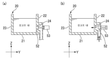
상술한 제1 실시형태에서는, 연속 응고기는, 응고조(20)의 입구 부근에 있어서, 응고조(20)의 측벽(22)으로부터 응고제 함유 두유를 공급하는 공급구(24)를 갖는 구성으로 하고 있지만, 제2 실시형태에서는, 응고조(20)가 공급구(24)를 개폐하는 개폐 부재를 갖는 구성으로 하여, 공급구(24)로부터의 액누출이나 역류를 방지하도록 하고 있다.In the first embodiment described above, the continuous coagulator is configured to have a
[0056] 구체적으로, 도 10에 확대하여 나타낸 바와 같이, 공급구(24)를 갖는 측벽(22)에 실린더(53)로 개폐 가능한 셔터식의 덮개(50)를 설치하고 있다.Specifically, as shown enlarged in FIG. 10, a shutter-
이 경우, 분할 블레이드(13)가 공급구(24)를 통과하고 있는 동안은, 셔터식의 덮개(50)가 닫혀 있다. 그리고, 분할 블레이드(13)가 공급구(24)를 통과하고 있지 않은 동안에, 후방의 분할 블레이드(13)가 최하단(最下端)에 오고, 측벽(22, 23)이나 바닥벽(21)의 내면과의 사이에서 두유 응고물의 누출이 없도록 시일성이 확실히 확보된 상태로부터, 셔터식의 덮개(50)가 열리고, 소정 시간 동안, 응고제 함유 두유를 계량하면서 응고조(20)의 응고 구획에 대략 액면 아래에서 흘려 넣기를 실시하고, 소정의 계량을 종료하면, 셔터식의 덮개(50)를 닫는다. 즉, 분할 블레이드(13)는 연속식의 구동이어도 되고, 배치식의 구동이어도 되지만, 응고제 함유 두유는 배치식의 공급이 된다. 또한, 적어도 다시 공급구(24)에 분할 블레이드(13)가 겹칠 때까지는, 셔터식의 덮개(50)가 열려, 응고제 함유 두유를 공급하고 있어도 된다.In this case, while the
[0057] 또한, 공급구(24)에 공간부가 있으면, 연속으로 주회하는 분할 블레이드(13)가 겹치기 전과 후에는, 반숙 내지는 미(未)응고된 응고제 함유 두유 응고물이 후방으로 누출된다. 이 때문에, 도 11에 나타낸 제1 변형예와 같이, 닫힌 상태에서 측벽(22)의 내면과 덮개면의 단차가 없는, 상하로 자유자재로 개폐 가능한 셔터식의 덮개(51)를 이용하는 것이 바람직하다. 또한, 도 12에 나타낸 제2 변형예와 같이, 시판 중인 새니터리 탱크(sanitary tank) 밸브(탱크 보텀 밸브)(52)를 이용하여, 닫힌 상태에서 밸브(52)의 선단부가 측벽(22)의 내면을 단차 없이 막는 형태여도 된다. 즉, 공급구(24)가 개구되는 응고조(20)의 측벽에 형성된 구멍(공간부)을 일시적으로 메워, 공급구(24)를 평탄하게 막는 개폐 부재이면 된다.[0057] In addition, if there is a space in the
또한, 제1 및 제2 변형예에 있어서도, 분할 블레이드(13)와 공급구(24)가 겹치는 타이밍에 개폐 부재(셔터식의 덮개(51), 탱크 밸브(52))가 개폐되는 데 맞춰, 응고제 함유 두유의 공급도 단속적(배치식 공급)이 된다.Also, in the first and second modifications, the opening and closing members (shutter-
[0058] 단, 상기 실시형태와 같이, 공급구(24)에 개폐 부재를 설치하지 않는 경우에는, 응고 구획에 공급하는 응고제 함유 두유의 액면 이상에 공급구(24)를 설치하는 것이 바람직하며, 그 경우에는, 응고제 함유 두유의 공급은 연속식이어도 된다.However, as in the above embodiment, when the opening and closing member is not provided in the
또한, 공급구(24)가 액면 아래이며, 공급구(24)의 구멍으로부터 다소의 누출이 발생하더라도, 액위(液位)가 그다지 높지 않고, 분할 블레이드(13)의 이동 속도도 그다지 늦지 않는다면(공급구(24)를 통과할 때는 일순간, 이동 속도를 빨리 해도 됨.), 누출되는 양은 소량으로 문제가 없으므로, 이 경우도, 개폐 부재 자체를 설치하지 않는 구성으로 해도 된다.In addition, if the
[0059] 또한, 분할 블레이드인 고무제 스크레이퍼(개폐 부재)를 길게 하여, 해당 스크레이퍼를 충분히 휘게 하고, 응고조(20)의 내면과 접하도록 하여, 공급구(24)를 스크레이퍼의 면으로 막도록 해도 된다.[0059] In addition, a rubber scraper (opening and closing member), which is a split blade, is lengthened, the scraper is sufficiently bent, and brought into contact with the inner surface of the
[0060] 구체적으로, 도 13에 나타낸 제3 변형예에서는, 공급구(24)가 응고조(20)의 양 측벽(22, 23)에 형성되는 경우, 고무제의 스크레이퍼(13a)를 폭방향으로 길게 형성하여, 측벽(22, 23)의 공급구(24)를 일시적으로 막도록 하고 있다. 또한, 이 고무제의 스크레이퍼(13a)는, 한쪽 측벽에만 공급구(24)가 있는 경우에도 적용할 수 있다. 또한, 도 14에 나타낸 제4 변형예에서는, 공급구(24)가 응고조(20)의 바닥벽(21)에 형성되는 경우, 고무제의 스크레이퍼(13b)를 상하 방향으로 길게 형성하여, 바닥벽(21)의 공급구(24)를 일시적으로 막도록 하고 있다.Specifically, in the third modified example shown in FIG. 13, when the
상기 제3 및 제4 변형예의 경우에는, 모두 응고제 함유 두유의 공급을 연속으로 행해도 된다.In the case of the said 3rd and 4th modification, you may supply coagulant-containing soymilk continuously.
[0061] 또한, 도 15에 나타낸 제5 변형예에서는, 응고조(20)의 한쪽 측벽(22)의 근접한 위치에 두 군데의 공급구(24a, 24b)를 설치하여, 응고제 함유 두유를 연속 공급하고 삼방 밸브(56)를 이용하여 공급구를 전환하며 연속 응고기에 공급하고 있다.[0061] In addition, in the fifth modified example shown in FIG. 15, two
분할 블레이드(13)와 공급구(24b)가 약간이라도 겹치는 위치에서는, 삼방 밸브(56)에 의해 공급 방향을 변경하여, 공급구(24b)로부터의 공급은 실시하지 않는 것으로 하고, 공급구(24a)로부터의 공급을 계속하는 것으로 한다. 이 경우, 응고제 함유 두유는 연속 공급되고, 분할 블레이드(13)도 연속 구동된다. 따라서, 배치식 응고기와 같이 일시 공급 정지나 에지 차단은 불필요하고, 응고 편차가 적어져, 보다 균일한 응고 품질이 된다. 2개의 노즐(57)의 수평 중심(芯) 간 거리 a는, 분할 블레이드(13)의 피치 b, 공급구(24)의 개구 수평 폭 c로 한 경우, b>2c, b>a, a=b/2, c≤a≤b-c라는 관계가 되는 사이즈가 바람직하다.At a position where the
[0062] 믹서(2)로부터 응고제 함유 두유를 연속 공급하면서, 응고조(20)의 두 군데의 공급구(24a, 24b)에 번갈아 공급하고 있다. 또한, 도시하지 않지만, 각 공급구에는, 탱크 밸브 등의 개폐 부재가 설치되어 있다.While continuously supplying coagulant-containing soymilk from the
우선, 응고제 함유 두유가 우측의 유로를 통해 구획 A에 공급되는 한편, 좌측의 유로는 분할 블레이드(13)에 겹치므로 닫혀 있다.First, coagulant-containing soymilk is supplied to the section A through the right passage, while the left passage overlaps the
다음으로, 분할 블레이드(13)가 좌측으로 나아가다가, 우측의 공급구(24a)에 겹치면, 삼방 밸브(56)가 전환되고, 계속해서, 응고제 함유 두유가 좌측의 유로를 통해 구획 A에 공급되고, 소정량의 공급이 종료된다.Next, when the
[0063] 분할 블레이드(13)가 더 좌측으로 나아가다가, 좌측의 공급구(24b)에 겹치면, 삼방 밸브(56)가 전환되고, 응고제 함유 두유가 우측의 유로를 통해 구획 B에 공급된다.[0063] When the
이후, 이를 반복하여, 응고제 함유 두유는 연속적으로 공급되고 있다. 따라서, 배치식 응고기와 같이 에지 차단은 불필요하고, 응고 편차가 적어져, 보다 균일한 응고 품질이 된다.Thereafter, by repeating this, coagulant-containing soymilk is continuously supplied. Therefore, edge blocking is unnecessary as in a batch type coagulator, and the coagulation variation is reduced, resulting in more uniform coagulation quality.
또한, 응고조(20)의 측벽(22)에, 세 군데 이상의 공급구(24)를 설치한 경우에는, 공급구(24)의 수에 따른 전환 밸브를 설치해도 된다.In the case where three or
[0064] (제3 실시형태)[0064] (third embodiment)
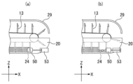
다음으로, 제3 실시형태에서는, 도 16에 나타낸 바와 같이, 응고조(20)와, 상측의 무단 형상 반송 컨베이어(31) 사이에서, 하측의 무단 형상 반송 컨베이어(41)의 하측 포(42)의 상방에는, 으깸 장치(60)가 설치되어 있다.Next, in the third embodiment, as shown in FIG. 16, between the
또한, 으깸 장치(60)의 하방의 위치에, 으깸 장치(60)가 접촉 가능한 보호판(61)이 설치된다. 이 때문에, 하측의 무단 형상 반송 컨베이어(41)의 하측 포(42)가, 보호판(61)을 우회하도록, 안내 롤(62, 63) 등을 이용하여, 하방으로 눌려 내려가며 안내된다.Further, at a position below the crushing
[0065] 이에 의해, 보호판(61)의 상면에서 두유 응고물의 바닥까지 확실히 으깰 수 있고, 하측 포(42)로부터의 이수를 촉진하여, 탈수가 좋아진다. 나아가, 약간 단단하며, 균등한 경도의 두부를 얻을 수 있다. 따라서, 종래, 하측 포(42)를 보호하기 위해, 하측 포(42)로부터 위로 5~10mm 이격된 높이에서 으깨었던 것에 의해, 바닥면이 거의 으깨지지 않아, 「2층 두부」가 된다는 과제를 해소할 수 있다.[0065] This makes it possible to reliably crush the soymilk coagulum from the upper surface of the
또한, 보호판(61)의 상면은, 으깸 장치(60)의 하방의 위치에 대해 상류측 및 하류측의 하측 포(42)의 부분과 동일한 평면이 되도록 배치되어, 두유 응고물을 원활히 반송할 수 있다.In addition, the upper surface of the
[0066] 또한, 으깸 장치(60)가 접촉 가능한 보호판(61)은, 도 17의 (a)나 도 17의 (b)에 나타낸 바와 같이, 안내 롤(63)의 기능을 겸하는 것이어도 되고, 구체적으로, 보호판(61a, 61b)은, 하측 포(42)에 손상을 주지 않는 두께를 가지며, 모서리가 둥그스름한 모따기가 실시된다. 도 17의 (a)의 보호판(61a)은, 상면측과 하면측의 양면을 만곡한 타원 형상으로 하고 있고, 도 17의 (b)의 보호판(61b)은, 상면측을 평탄하게 하는 한편, 하면측을 만곡시키고 있다. 또한, 보호판(61)은 스테인리스제 등의 강성이 있는 금속제나, 수지제나 고무제로 탄성이 있는 재료로 이루어진 것이어도 된다.[0066] In addition, as shown in FIG. 17 (a) or FIG. 17 (b), the
[0067] 따라서, 본 발명은, 상술한 두부류 제조 장치를 이용함으로써, 비단두부, 소프트 두부, 목면두부, 유부 생지, 두부 튀김·두부 설튀김 생지, 견두부(堅豆腐), 더우화(豆花; tofu pudding) 등을 제조할 수 있다.[0067] Therefore, the present invention, by using the above-described tofu production apparatus, silken tofu, soft tofu, cotton tofu, fried tofu dough, fried tofu · fried tofu dough, curdled tofu (堅豆腐), Douhua (豆花); tofu pudding) and the like.
구체적으로는, 푸딩 형상이며 부드러운 두유 응고물을 그대로 프레스하지 않고, 비단두부나 더우화(두부 푸딩)로 할 수 있다. 또한, 푸딩 형상의 두유 응고물을 가볍게 프레스하여 천무늬만 내어, 소프트 두부로 할 수 있다. 나아가, 푸딩 형상의 두유 응고물을 상기 으깸 장치(60)에 의해 적절히 원하는 정도로 으깨고, 프레스함으로써, 목면두부, 두부 튀김·두부 설튀김 생지, 견두부, 더우화가 제조된다.Specifically, the pudding-shaped, soft soybean milk coagulum can be made into silken tofu or tofu (tofu pudding) without being pressed as it is. In addition, soft tofu can be obtained by lightly pressing the pudding-shaped soybean milk curd to produce only fabric patterns. Furthermore, the pudding-shaped soymilk curd is crushed to a desired degree appropriately by the crushing
유부나 견두부·시마두부(島豆腐; Okinawan-style tofu)는 일반적으로 순두부 형상 응고물로 제조하지만, 약간 묽은 두유로부터 얻은 푸딩 형상에 가까운 응고물을 충분히 잘게 으깨어도 제조하는 것이 가능하다. 그렇게 하는 것이 수분보유성이 좋고 맛이 빠져나가기 어려운 두부질이 되어, 보일(boil) 살균 등 보존 일자가 길어지더라도 맛있는 상태를 유지하기 쉬워진다.Tofu and Okinawan-style tofu are generally produced from soft tofu-like curds, but it is also possible to produce curds close to pudding-like curds obtained from slightly diluted soymilk by sufficiently finely crushing them. Doing so makes tofu quality with good moisture retention and difficult to escape taste, and it is easy to maintain a delicious state even if the preservation date is prolonged such as boiling sterilization.
[0068] 또한, 상술한 각 두부류 제조 장치(1)에서는, 연속 응고기(10)는, 고형분이 3~20%wt, 바람직하게는 5~15%wt인 50~95℃(바람직하게는 60~85℃)의 두유를 응고제에 의해 응고 숙성시킴으로써, 푸딩 형상의 두유 응고물을 생성한다.[0068] In addition, in each of the tofu production apparatuses 1 described above, the
[0069] 응고 숙성 후, 「웃물」과 응고물이 분리되는, 이른바 "순두부 형상"의 응고 상태로 해도 되지만, 본 발명은, 푸딩 형상, 비단두부 형상의 수분보유성이 좋은 응고 상태에 있어서, 큰 효과를 기대할 수 있다.[0069] After coagulation and aging, it may be in a solidified state in a so-called "soft tofu shape" in which "sweet water" and coagulum are separated, but in the present invention, in a solidified state in a pudding shape or silky tofu shape with good water retention, A great effect can be expected.
[0070] 또한, 부드러운 푸딩 형상의 두유 응고물을 별로 부서뜨리지 않고 성형기의 하측 포 위에 싣고, 적절히, 으깸 장치(60)로 으깨어, 수분보유성이 좋은 소프트한 고품질의 목면두부(더우화식)를 성형해도 되고, 이에 의해, 위생적이면서 생력화되어 생산 효율이 좋아, 양산화를 가능하게 한다.[0070] In addition, the soft pudding-shaped soymilk coagulum is loaded on the lower fabric of the molding machine without much crushing, and appropriately crushed with the crushing
[0071] 또한, 응고제로서는, 두유와 혼합 후, 응고가 시작될 때까지의 시간이 5~180초, 바람직하게는 10~120초인 지효성 응고제나, 유화(乳化) 간수도 적합하게 이용할 수 있다. 예컨대, 시판 중으로 지효성인 응고제이면 되고, 염화마그네슘을 오일이나 유화제로 감싼 유화 간수 외에, 예컨대, GDL(글루코노델타락톤), 정제 분말(황산칼슘, 조립(粗粒)), 식염, 트랜스글루타미나아제와 같은 지효성 응고제를 사용한다. 한천, 카라기난, 커들란, 전분 등의 겔화력이 있는 부재료(副材)(증점 다당류)를 포함해도 된다. 또한, 이들을 적절히 배합한 제법이어도 된다. 응고제로서, 유화 간수를 사용한 경우에는, 단맛도 늘릴 수 있다. 지효성을 보조하기 위해, 두유에 알칼리성으로 조정하는 pH 조정제(탄산수소나트륨((重曹)) 등)나 킬레이트 작용을 갖는 폴리인산계 첨가물 등을 병용해도 된다.[0071] As the coagulant, a delayed-acting coagulant whose time until coagulation starts after mixing with soymilk is 5 to 180 seconds, preferably 10 to 120 seconds, or emulsified bittern can also be suitably used. For example, as long as it is a commercially available coagulant of sustained release, besides emulsified bittern in which magnesium chloride is wrapped with oil or emulsifier, for example, GDL (gluconodeltalactone), purified powder (calcium sulfate, granulated), salt, transglutamine Use a slow-acting coagulant such as Nase. Auxiliary materials (polysaccharides thickening) with gelling power, such as agar, carrageenan, curdlan, and starch, may also be included. Moreover, the manufacturing method which mix|blended these suitably may be sufficient. As a coagulant, when emulsified bittern is used, sweetness can also be increased. In order to assist the sustained release, a pH adjuster (sodium bicarbonate, etc.) that adjusts alkalinity to soymilk, a polyphosphoric acid-based additive having a chelating action, or the like may be used in combination.
[0072] 이상, 도면을 참조하면서 각종 실시형태에 대해 설명하였으나, 본 발명은 이러한 예에 한정되지 않음은 물론이다. 당업자라면, 청구범위에 기재된 범주 내에 있어서, 각종 변경예 또는 수정예를 생각해 낼 수 있음은 분명하며, 이들에 대해서도 당연히 본 발명의 기술적 범위에 속하는 것으로 이해된다. 또한, 발명의 취지를 벗어나지 않는 범위에 있어서, 상기 실시형태에 있어서의 각 구성 요소를 임의로 조합해도 된다.[0072] Although various embodiments have been described with reference to the drawings, it goes without saying that the present invention is not limited to these examples. It is clear that those skilled in the art can come up with various changes or modifications within the scope described in the claims, and it is understood that these also naturally fall within the technical scope of the present invention. In addition, within a range not departing from the spirit of the invention, you may combine each constituent element in the said embodiment arbitrarily.
[0073] 또한, 본 출원은, 2020년 7월 13일에 출원된 일본 특허출원(특허출원 제2020-119817호)에 기초한 것이며, 그 내용은 본 출원 내에 참조로서 원용된다.[0073] This application is based on the Japanese Patent Application (Patent Application No. 2020-119817) filed on July 13, 2020, the contents of which are incorporated herein by reference.
[0074] 1 두부류 제조 장치
10 연속 응고기
11 무단 형상 컨베이어
12 컨베이어 벨트(무단 체인)
13 분할 블레이드
20 응고조
24 공급구
30 연속 성형기
31 상측의 무단 형상 반송 컨베이어
32 상측 포
41 하측의 무단 형상 반송 컨베이어
42 하측 포
50, 51 셔터식의 덮개(개폐 부재)
52 탱크 밸브(개폐 부재)[0074] 1 tofu manufacturing device
10 continuous coagulator
11 Endless shape conveyor
12 conveyor belt (endless chain)
13 split blade
20 coagulation bath
24 supply port
30 continuous forming machine
31 Upper endless shape conveyor
32 upper side guns
41 Lower endless shape conveyor
42 lower gun
50, 51 shutter-type cover (closing member)
52 tank valve (closing member)
Claims (14)
하측 포(下布; lower cloth)가 감기는 하측의 무단 형상 반송(搬送) 컨베이어와 상측 포(上布; upper cloth)가 감기는 상측의 무단 형상 반송 컨베이어를 적어도 갖는 연속 성형기
를 갖는 두부류 제조 장치로서,
상기 하측의 무단 형상 반송 컨베이어는, 상기 하측 포가 상기 응고조의 출구단부(出口端部)의 하방에 위치하도록, 상방에서 볼 때 상기 응고조와 오버랩되고,
상기 응고조의 바닥벽(底壁)은, 상기 응고조의 입구 부근으로부터 해당 출구단부를 향해 대략 수평으로 형성되는, 두부류 제조 장치.An endless conveyor in which a plurality of dividing blades are attached to the surface of the conveyor belt at predetermined intervals, and a solidification tank having a concave cross section in which the dividing blades pass through the inside ( A pear-shaped continuous coagulator having a concave shape;
A continuous molding machine having at least a lower endless form conveyor on which lower cloth is wound and an upper endless form conveyor on which upper cloth is wound.
As a tofu manufacturing apparatus having,
The lower endless conveyor overlaps the coagulation tank when viewed from above so that the lower fabric is located below the exit end of the coagulation tank,
The bottom wall of the coagulation tank is formed substantially horizontally from the vicinity of the inlet of the coagulation tank toward the corresponding outlet end.
상기 응고조와 상기 상측의 무단 형상 반송 컨베이어는, 직선형으로 나란히 배치되어 있는, 두부류 제조 장치.According to claim 1,
The tofu manufacturing apparatus according to claim 1 , wherein the coagulation tank and the upper endless conveyor are arranged side by side in a straight line.
상기 연속 응고기의 무단 형상 컨베이어는, 상기 응고조의 출구 부근에 있어서, 상기 분할 블레이드의 선단 내지 부착단(取付端)이 상승하도록, 상기 연속 응고기의 이송 방향을 향해 상방으로 경사지는, 두부류 제조 장치.According to claim 1 or 2,
The endless conveyor of the continuous coagulator, in the vicinity of the exit of the coagulation tank, inclines upward toward the conveying direction of the continuous coagulator so that the tip or the attached end of the dividing blade rises. Device.
상기 연속 응고기는, 상기 응고조의 입구 부근에 있어서, 상기 응고조의 양 측벽 및 바닥벽 중 적어도 한 군데에, 두유, 응고제, 및 응고제 함유 두유 혹은 세정약액 중 어느 것을 공급하는 공급구 내지는 이들을 배출하는 배출구를 갖는, 두부류 제조 장치.According to any one of claims 1 to 3,
In the vicinity of the inlet of the coagulation tank, the continuous coagulator supplies soymilk, coagulant, and coagulant-containing soymilk or cleaning liquid to at least one of both side walls and bottom walls of the coagulation tank, or a discharge port for discharging them Tofu manufacturing apparatus having a.
상기 응고조는, 상기 공급구를 개폐하는 개폐 부재를 갖는, 두부류 제조 장치.According to claim 4,
The coagulation tank has an opening and closing member for opening and closing the supply port.
상기 개폐 부재는, 상기 공급구가 개구되는 상기 응고조의 측벽에 형성된 구멍을 메워, 상기 공급구를 평탄하게 막도록 배치되는, 두부류 제조 장치.According to claim 5,
The opening and closing member is disposed so as to flatly block the supply port by filling a hole formed in a sidewall of the coagulation tank through which the supply port is opened.
상기 분할 블레이드는, 고무제의 스크레이퍼이며,
상기 개폐 부재는, 상기 응고조의 내면과 접촉하여 휨으로써 상기 공급구를 막는, 상기 고무제의 스크레이퍼에 의해 구성되는, 두부류 제조 장치.According to claim 5 or 6,
The split blade is a rubber scraper,
The tofu manufacturing apparatus according to claim 1, wherein the opening and closing member is constituted by the rubber scraper that contacts the inner surface of the coagulation tank and closes the supply port by bending.
상기 연속 응고기는, 상기 연속 성형기와 동기하여 구동되는, 두부류 제조 장치.According to any one of claims 1 to 7,
The continuous coagulator is driven in synchronization with the continuous forming machine.
상기 응고조의 폭은, 상기 연속 성형기의 프레스부의 폭과 거의 동일한, 두부류 제조 장치.According to any one of claims 1 to 8,
The width of the coagulation bath is substantially the same as the width of the press section of the continuous forming machine.
상기 응고조와, 상기 상측의 무단 형상 반송 컨베이어 사이에서, 상기 하측의 무단 형상 반송 컨베이어의 하측 포의 상방에는, 으깸 장치가 설치되며,
상기 으깸 장치의 하방의 위치에서는, 상기 으깸 장치가 접촉 가능한 보호판이 배치되고,
상기 하측의 무단 형상 반송 컨베이어의 하측 포는, 상기 보호판을 우회하도록, 하방으로 눌려 내려가며 안내되는, 두부류 제조 장치.According to any one of claims 1 to 9,
Between the coagulation tank and the upper endless conveyor, a crushing device is installed above the lower fabric of the lower endless conveyor,
At a position below the crushing device, a protective plate contactable with the crushing device is disposed,
The tofu manufacturing apparatus according to claim 1 , wherein the lower fabric of the lower endless conveyor is guided while being pressed downward to bypass the guard plate.
상기 연속 응고기는, 상기 무단 형상 컨베이어의 상방을 덮는 커버를 더 구비하는, 두부류 제조 장치.According to any one of claims 1 to 10,
The continuous coagulator further includes a cover covering an upper portion of the endless conveyor.
상기 무단 형상 컨베이어에서는, 상기 컨베이어 벨트를 연결하는 체인, 및 해당 체인이 걸쳐지는 스프로킷이, 상기 응고조의 측벽의 폭방향 외측에 배치되는, 두부류 제조 장치.According to any one of claims 1 to 11,
In the endless conveyor, a chain connecting the conveyor belt and a sprocket over which the chain spans are disposed outside the side wall of the coagulation tank in the width direction.
상기 연속 응고기는, 50~95℃, 고형분이 3~20%wt인 두유를 응고제에 의해 응고 숙성시킴으로써, 푸딩 형상의 두유 응고물을 생성하고,
상기 연속 성형기는, 상기 하측 포에 의해 상기 두유 응고물을 반송하고, 필요에 따라 프레스함으로써, 상기 두부류를 성형하는, 두부류 제조 방법.A tofu production method for producing tofu using the tofu production device according to any one of claims 1 to 12,
The continuous coagulator produces a pudding-shaped soymilk coagulum by coagulating and aging soymilk having a solid content of 3 to 20%wt at 50 to 95 ° C. with a coagulant,
The tofu production method according to claim 1 , wherein the continuous molding machine conveys the soybean milk coagulum by the lower cloth and presses as necessary to shape the tofu.
상기 응고제는, 지효성 응고제, 또는 유화(乳化) 간수인, 두부류 제조 방법.According to claim 13,
The coagulant is a slow-acting coagulant or an emulsified bittern, tofu production method.
Applications Claiming Priority (3)
| Application Number | Priority Date | Filing Date | Title |
|---|---|---|---|
| JP2020119817 | 2020-07-13 | ||
| JPJP-P-2020-119817 | 2020-07-13 | ||
| PCT/JP2021/025947 WO2022014491A1 (en) | 2020-07-13 | 2021-07-09 | Soybean curd production device and soybean curd production method |
Publications (1)
| Publication Number | Publication Date |
|---|---|
| KR20230036058A true KR20230036058A (en) | 2023-03-14 |
Family
ID=79555496
Family Applications (1)
| Application Number | Title | Priority Date | Filing Date |
|---|---|---|---|
| KR1020227034210A KR20230036058A (en) | 2020-07-13 | 2021-07-09 | Tofu manufacturing device and tofu manufacturing method |
Country Status (5)
| Country | Link |
|---|---|
| US (1) | US20230137565A1 (en) |
| JP (1) | JPWO2022014491A1 (en) |
| KR (1) | KR20230036058A (en) |
| CN (1) | CN115279203A (en) |
| WO (1) | WO2022014491A1 (en) |
Families Citing this family (1)
| Publication number | Priority date | Publication date | Assignee | Title |
|---|---|---|---|---|
| KR102623487B1 (en) * | 2022-01-29 | 2024-01-10 | 서신식품 주식회사 | Crushing system for bean curd |
Citations (4)
| Publication number | Priority date | Publication date | Assignee | Title |
|---|---|---|---|---|
| JPS4885757A (en) | 1972-02-17 | 1973-11-13 | ||
| JPS4885756A (en) | 1972-02-17 | 1973-11-13 | ||
| JPS5170862A (en) | 1974-12-13 | 1976-06-18 | Takai Sofu & Soymilk Equip | |
| JPS51106779A (en) | 1975-03-12 | 1976-09-21 | Takai Sofu & Soymilk Equip |
Family Cites Families (7)
| Publication number | Priority date | Publication date | Assignee | Title |
|---|---|---|---|---|
| JPS5137342B2 (en) * | 1973-06-06 | 1976-10-15 | ||
| JPH01320965A (en) * | 1988-06-21 | 1989-12-27 | Masamori Osada | Process for automatic preparation of bean curd and apparatus therefor |
| JPH02273151A (en) * | 1989-04-14 | 1990-11-07 | Sanyo Shokuhin Kk | Device for automatically and continuously producing 'tofu' |
| JPH0376554A (en) * | 1989-08-17 | 1991-04-02 | Sanyo Shokuhin Kk | Apparatus for automatic and continuous preparation of bean curd |
| JPH0391453A (en) * | 1989-09-01 | 1991-04-17 | Sanyo Shokuhin Kk | Cleaning method for automatic soybean-curd production unit |
| JP3258119B2 (en) * | 1993-03-25 | 2002-02-18 | ニチモウ株式会社 | Continuous coagulation device for tofu |
| JP2788429B2 (en) * | 1995-07-25 | 1998-08-20 | 株式会社ヤナギヤ | Method for producing tofu, apparatus for producing tofu, and apparatus for continuous production of tofu |
-
2021
- 2021-07-09 WO PCT/JP2021/025947 patent/WO2022014491A1/en active Application Filing
- 2021-07-09 US US17/906,740 patent/US20230137565A1/en active Pending
- 2021-07-09 KR KR1020227034210A patent/KR20230036058A/en unknown
- 2021-07-09 JP JP2022536322A patent/JPWO2022014491A1/ja active Pending
- 2021-07-09 CN CN202180021434.8A patent/CN115279203A/en active Pending
Patent Citations (4)
| Publication number | Priority date | Publication date | Assignee | Title |
|---|---|---|---|---|
| JPS4885757A (en) | 1972-02-17 | 1973-11-13 | ||
| JPS4885756A (en) | 1972-02-17 | 1973-11-13 | ||
| JPS5170862A (en) | 1974-12-13 | 1976-06-18 | Takai Sofu & Soymilk Equip | |
| JPS51106779A (en) | 1975-03-12 | 1976-09-21 | Takai Sofu & Soymilk Equip |
Also Published As
| Publication number | Publication date |
|---|---|
| CN115279203A (en) | 2022-11-01 |
| US20230137565A1 (en) | 2023-05-04 |
| JPWO2022014491A1 (en) | 2022-01-20 |
| WO2022014491A1 (en) | 2022-01-20 |
Similar Documents
| Publication | Publication Date | Title |
|---|---|---|
| EP3357350A1 (en) | Device for continuous molding of soybean curd | |
| KR20230036058A (en) | Tofu manufacturing device and tofu manufacturing method | |
| US8443720B2 (en) | Continuous curding machine for tofu products | |
| US8221816B1 (en) | Process for preparing low moisture filata cheese | |
| CA1232792A (en) | Apparatus for producing frozen confections | |
| WO2010115407A2 (en) | Apparatus for producing flake ice and method for cleaning, descaling and/or disinfecting an apparatus for producing flake ice | |
| CN105942550A (en) | Peeling machine | |
| CA1134197A (en) | Cheese manufacture | |
| JP2010227092A (en) | Method and apparatus for dehydrating and molding tofu and deep-fried tofu dough | |
| JP6874240B2 (en) | Tofu continuous production equipment | |
| JP2022017583A (en) | Coagulating device of soybean curd | |
| AU684124B2 (en) | An immersion freezer | |
| US2980538A (en) | Process and apparatus for washing curd for cottage cheese | |
| CN107691964A (en) | A kind of system for carrying out disinfection and drying to packaged food | |
| JP2020078349A (en) | Apparatus for continuously molding soybean curd | |
| US3465439A (en) | Apparatus for the production of cottage cheese | |
| JP2013244121A (en) | Water supply and discharge device of boiling device | |
| JPWO2022014491A5 (en) | ||
| US4961248A (en) | Scalder apparatus | |
| CN212768280U (en) | Auxiliary mechanism for blanking of steamed stuffed bun machine | |
| WO2022050155A9 (en) | Method and device for manufacturing tofu products | |
| US3554765A (en) | Preparation of plasticized cheese | |
| WO2019188057A1 (en) | Food coating device and food production method | |
| JP2021176799A (en) | Transport mechanism for soybean curd and continuous manufacturing apparatus for soybean curd | |
| EP1175826B1 (en) | Curd draining apparatus and curd draining process |