WO2022014288A1 - ガラス物品の製造方法 - Google Patents
ガラス物品の製造方法 Download PDFInfo
- Publication number
- WO2022014288A1 WO2022014288A1 PCT/JP2021/023864 JP2021023864W WO2022014288A1 WO 2022014288 A1 WO2022014288 A1 WO 2022014288A1 JP 2021023864 W JP2021023864 W JP 2021023864W WO 2022014288 A1 WO2022014288 A1 WO 2022014288A1
- Authority
- WO
- WIPO (PCT)
- Prior art keywords
- furnace
- molded body
- heater
- glass
- molding
- Prior art date
- Legal status (The legal status is an assumption and is not a legal conclusion. Google has not performed a legal analysis and makes no representation as to the accuracy of the status listed.)
- Ceased
Links
Images





Classifications
-
- C—CHEMISTRY; METALLURGY
- C03—GLASS; MINERAL OR SLAG WOOL
- C03B—MANUFACTURE, SHAPING, OR SUPPLEMENTARY PROCESSES
- C03B17/00—Forming molten glass by flowing-out, pushing-out, extruding or drawing downwardly or laterally from forming slits or by overflowing over lips
- C03B17/06—Forming glass sheets
-
- Y—GENERAL TAGGING OF NEW TECHNOLOGICAL DEVELOPMENTS; GENERAL TAGGING OF CROSS-SECTIONAL TECHNOLOGIES SPANNING OVER SEVERAL SECTIONS OF THE IPC; TECHNICAL SUBJECTS COVERED BY FORMER USPC CROSS-REFERENCE ART COLLECTIONS [XRACs] AND DIGESTS
- Y02—TECHNOLOGIES OR APPLICATIONS FOR MITIGATION OR ADAPTATION AGAINST CLIMATE CHANGE
- Y02P—CLIMATE CHANGE MITIGATION TECHNOLOGIES IN THE PRODUCTION OR PROCESSING OF GOODS
- Y02P40/00—Technologies relating to the processing of minerals
- Y02P40/50—Glass production, e.g. reusing waste heat during processing or shaping
- Y02P40/57—Improving the yield, e-g- reduction of reject rates
Definitions
- the present invention relates to a method for manufacturing a glass article.
- the overflow downdraw method may be used as a method for manufacturing glass articles such as glass plates.
- the molding apparatus includes a substantially wedge-shaped molded body in a molding furnace.
- the molten glass supplied to the molded body overflows from the groove formed at the top of the molded body, and then flows along both outer surfaces of the molded body and joins at the lower end portion.
- a strip-shaped glass ribbon is continuously formed from the molten glass.
- Patent Document 1 since the front and back surfaces of the glass ribbon to be molded do not come into contact with the molded body during the molding process, there is an advantage that a smooth glass ribbon without scratches or the like can be molded on the front and back surfaces (for example, Patent Document 1). reference).
- the temperature around the molded body is raised before the operation (before supplying the molten glass to the molded body). Then, a temperature raising step of raising the temperature of the molded product is performed.
- the molded body is liable to be damaged such as cracked by the thermal shock caused by the temperature fluctuation of the molded body.
- the lower part of the molded body has a small cross-sectional area (thickness) due to the substantially wedge-shaped shape, so that the heat capacity is small and it is easy to cool.
- tensile stress is likely to occur in the lower part of the molded body due to bending due to its own weight. Therefore, when the temperature of the lower part of the molded body is lowered due to the updraft generated in the molding furnace or the like, the molded body is liable to be damaged starting from the lower part of the molded body.
- the present invention suppresses damage to the molded product used in the overflow downdraw method in the temperature raising step.
- the present invention which was invented to solve the above problems, is a method for manufacturing a glass article by an overflow downdraw method, in which a temperature raising step of raising a temperature of a molded body arranged in a molding furnace and a temperature raising step of raising the temperature of the molded body are performed. It is equipped with a molding process in which molten glass is supplied to the body and a glass ribbon is molded from the molten glass. do.
- the heater inside the furnace is arranged in the molding furnace in this way, the heater can be arranged near the lower part of the molded body as compared with the case where the heater outside the furnace is arranged outside the molding furnace. As a result, even when an updraft or the like is generated in the molding furnace, the temperature of the lower part of the molded body can be stabilized by the heater in the furnace, so that damage such as cracking of the molded body can be reduced.
- the molded body when the molten glass is supplied to the molded body, the molded body is covered with the high-temperature molten glass, so that the temperature drop at the lower part of the molded body is less likely to occur.
- the molten glass and / or the glass ribbon is overheated, and it becomes difficult to stably form the glass ribbon. There is a risk. Therefore, after supplying the molten glass to the molded product, it is preferable to reduce or stop the heating by the heater in the furnace as in the above configuration.
- the heating of the lower part of the molded product by the heater in the furnace can be easily and surely reduced or stopped.
- the heater in the furnace is separated from the molten glass and the glass ribbon, there is an advantage that the heater in the furnace does not get in the way in the production process.
- the heater in the furnace sandwiches a pair of both outer surfaces of the lower part of the molded body in the thickness direction of the glass ribbon or the passing portion of the glass ribbon below the lower part of the molded body from both sides in the thickness direction. It is preferable that they are arranged so as to form a ribbon.
- the lower part of the molded product can be heated uniformly from both sides.
- the heater in the furnace is arranged in the molding furnace through the opening for the transfer roller of the glass ribbon provided in the side wall portion of the molding furnace.
- the heater in the furnace can be arranged without providing a new opening in the molding furnace, so that an increase in equipment cost can be suppressed.
- thermometer for measuring the temperature of the lower part of the molded body is arranged in the molding furnace.
- the temperature control of the lower part of the molded body becomes easy, and the damage of the molded body can be further reduced.
- a first outside furnace heater for heating the upper part of the molded body is arranged at a position corresponding to the upper part of the side wall portion of the molding furnace, and a position corresponding to the lower part of the side wall portion of the molding furnace.
- a second outside furnace heater that heats the lower part of the molded body is arranged in, and a third outside furnace heater that heats the upper part of the molded body is arranged at a position corresponding to the ceiling of the molding furnace.
- the molded body may be further heated by the first out-of-firer heater, the second out-of-firer heater and the third out-of-firer heater.
- the temperature of the molded body can be raised while the desired temperature distribution is given to the molded body.
- the X direction and the Y direction are the horizontal direction
- the Z direction is the vertical direction.
- the direction corresponding to the width direction of the glass ribbon Gr to be molded is referred to as the width direction X
- the direction corresponding to the thickness direction of the glass ribbon Gr to be molded is referred to as the thickness direction Y.
- duplicate description may be omitted.
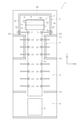
- the method for manufacturing a glass article according to the first embodiment is to manufacture a glass plate G as a glass article by an overflow down draw method using a glass article manufacturing apparatus 1.
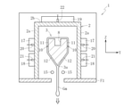
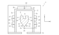
- a temperature raising step (FIGS. 3 and 4) for raising the temperature of the molded body 3 arranged in the molding furnace 2 and a molten glass Gm are supplied to the heated molded body 3 to supply the molten glass Gm.
- a production process (FIGS. 1 and 2) including a molding process of molding the glass ribbon Gr from the above.
- the production process is carried out after the temperature raising process.
- the production step includes a molding step, a slow cooling step, a cooling step, and a cutting step.
- the manufacturing apparatus 1 in the production process includes a molding furnace 2, a slow cooling furnace 4 located below the molding furnace 2, a cooling chamber 5 located below the slow cooling furnace 4, and a cooling chamber 5. It is provided with a cutting chamber 6 located below.
- a partition member having an opening (for example, a slit) through which the glass ribbon Gr passes between the forming furnace 2 and the slow cooling furnace 4, between the slow cooling furnace 4 and the cooling chamber 5, and between the cooling chamber 5 and the cutting chamber 6, respectively. (For example, the floor of a building) It is partitioned by F1, F2, and F3.
- the molding furnace 2 is a region for molding the glass ribbon Gr from the molten glass Gm by the overflow down draw method. Inside the molding furnace 2, a molded body 3 for molding the glass ribbon Gr from the molten glass Gm and a first transport roller 7 for cooling both ends of the glass ribbon Gr molded by the molded body 3 in the width direction X are provided. Have been placed.
- the molded body 3 is formed of a long refractory material along the width direction X.
- the refractory include zircon, zirconia, alumina, magnesia, and xenotime.
- a groove portion (overflow groove) 8 formed along the width direction X is provided on the top of the molded body 3.
- a supply pipe 9 is connected to one end side of the groove portion 8 in the width direction X.
- the molten glass Gm is supplied into the groove 8 through the supply pipe 9.
- the method of supplying the molten glass Gm is not limited to this.
- the molten glass Gm may be supplied from both ends of the groove portion 8 in the width direction X, or the molten glass Gm may be supplied from above the groove portion 8.
- the molded body 3 has a symmetrical shape in the thickness direction Y.
- Both outer surfaces 10 of the thickness direction Y of the molded body 3 are a vertical surface portion 11 forming a planar shape along the vertical direction and an inclined surface portion 11 connected below the vertical surface portion 11 and forming a planar shape inclined with respect to the vertical direction. It is equipped with twelve.
- Each vertical plane portion 11 is a plane parallel to each other.
- Each inclined surface portion 12 is a plane inclined so as to approach each other in the thickness direction Y as it goes downward. That is, the molded body 3 has a wedge shape that tapers downward when viewed from the width direction X by forming each inclined surface portion 12, and the corner portion where the inclined surface portions 12 intersect is the lower end of the molded body 3. Part 3a is formed.
- the shape of the vertical surface portion 11 may be changed to an inclined surface, a curved surface, or the like, or may be omitted.
- the first transport roller 7 is configured as a roller pair that sandwiches each end of the glass ribbon Gr in the width direction X in the thickness direction Y immediately below the molded body 3.
- the first transfer roller 7 is a cantilever type roller and is always internally cooled in the molding process.
- the first transfer roller 7 is also referred to as a cooling roller or an edge roller.
- the first transport roller 7 may be provided in a plurality of stages (for example, two stages) in the vertical direction Z. For example, in the case of two upper and lower stages, it is preferable that the first transfer roller 7 in the upper stage is a drive roller and the first transfer roller 7 in the lower stage is a free roller.
- the slow cooling furnace 4 is a region for reducing the warp and internal strain of the glass ribbon Gr.
- a second transfer roller 13 is arranged inside the slow cooling furnace 4.
- the second transfer roller 13 is also referred to as an annealer roller.
- the second transfer roller 13 is configured as a pair of rollers that sandwich each end of the glass ribbon Gr in the width direction X in the thickness direction Y.
- the second transfer roller 13 may be a double-sided type roller arranged so as to straddle the entire width direction X of the glass ribbon Gr, but in the present embodiment, it is a cantilever type roller.
- the second transfer roller 13 is provided in a plurality of stages in the vertical direction Z.
- the cooling chamber 5 is a region for cooling the glass ribbon Gr to near room temperature.
- a third transfer roller 14 is arranged inside the cooling chamber 5.
- the third transfer roller 14 is configured as a pair of rollers that sandwich each end of the glass ribbon Gr in the width direction X in the thickness direction Y.
- the third transfer roller 14 may be a double-sided type roller arranged so as to straddle the entire width direction X of the glass ribbon Gr, but in the present embodiment, it is a cantilever type roller.
- the third transfer roller 14 is provided in a plurality of stages in the vertical direction Z.
- the second transfer roller 13 and / or the third transfer roller 14 may include those that do not sandwich both ends of the glass ribbon Gr in the width direction X. That is, the facing distance between the roller pairs constituting the second transport roller 13 and / or the third transport roller 14 is made larger than the thickness of both ends of the glass ribbon Gr in the width direction X, and the space between the roller pairs is set to the glass ribbon Gr. May pass through.
- both ends of the glass ribbon Gr obtained in the manufacturing apparatus 1 in the width direction X have ears that are thicker than the central portion in the width direction X due to the influence of shrinkage in the molding process and the like. include.
- the cutting chamber 6 is a region for cutting the glass ribbon Gr to a predetermined size to obtain a glass plate G as a glass article.
- a cutting device (not shown) for cutting the glass ribbon Gr is arranged inside the cutting chamber 6, inside the cutting chamber 6, a cutting device (not shown) for cutting the glass ribbon Gr is arranged.
- the method for cutting the glass ribbon Gr by the cutting device is, but is not limited to, scribe cutting in which a scribe line is formed on the glass ribbon Gr and then folded along the scribe line.
- the cutting method of the cutting device may be, for example, laser cutting or laser fusing.
- the glass plate G is a glass original plate (mother glass plate) from which one or more product glass plates are collected.
- the thickness of the product glass plate is, for example, 0.2 mm to 10 mm, and the size of the product glass plate is, for example, 700 mm ⁇ 700 mm to 3500 mm ⁇ 3500 mm.
- the product glass plate is used, for example, as a display substrate or a cover glass.
- the display substrate and cover glass are not limited to flat panels, and may be curved panels.
- molten glass Gm is supplied to the groove 8 of the molded body 3 and overflows from the groove 8 on both sides.
- the molten glass Gm is allowed to flow down along the respective vertical surface portions 11 and inclined surface portions 12 and rejoined at the lower end portion 3a.
- the strip-shaped glass ribbon Gr is continuously formed from the molten glass Gm (molding step).
- the glass ribbon Gr is slowly cooled (slow cooling step), and in the cooling chamber 5, the glass ribbon Gr is cooled to near room temperature (cooling step).
- the cutting step is a first cutting step of cutting the glass ribbon Gr in the width direction X for each predetermined length to obtain a glass plate G, and cutting and removing the ears at both ends of the glass plate G in the width direction X. Includes a second cutting step.
- the post-process of the molding process is not particularly limited.
- the production process may further include a cleaning process, an inspection process, a packaging process, and the like.
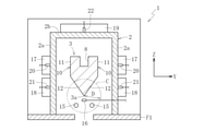
- the in-core heater 15 for heating the lower part of the molded body 3 and the temperature of the lower part of the molded body 3 are heated. It is equipped with an in-firer thermometer 16 for measuring.
- the lower portion of the molded body 3 means, for example, a portion corresponding to the inclined surface portion 12 of the molded body 3.
- the heaters 15 in the furnace are arranged so as to form a pair by sandwiching the passing portion of the glass ribbon Gr below the lower end portion 3a of the molded body 3 from both sides in the thickness direction Y.
- the in-core heater 15 is composed of a pair of rod-shaped heaters (for example, sheathed heaters) extending along the width direction X and facing each other in the thickness direction Y. Specifically, the in-furn heater 15 crosses the inside of the molding furnace 2 along the width direction X, and both ends thereof penetrate the side wall portion 2a of the molding furnace 2 and are held outside the molding furnace 2. ..
- a plurality of paired furnace heaters 15 may be arranged side by side in the vertical direction.
- the holding mode of the heater 15 in the furnace is not limited to the mode in which both ends are held outside the furnace (double-sided holding), and for example, the holding mode is a mode in which only one end is held outside the furnace (cantilever holding). There may be.
- the widthwise dimension W1 of the in-core heater 15 in the molding furnace 2 is arranged in a wider range than the widthwise dimension W2 of the lower end portion 3a of the molded body 3. That is, the heater 15 in the furnace heats the entire width of the lower end portion 3a of the molded body 3.
- the arrangement position of the heater 15 in the furnace is preferably within the range of the circle C centered on the lower end portion 3a of the molded body 3.
- the diameter D of the circle C is, for example, preferably 50 mm to 300 mm, more preferably 100 mm to 200 mm.
- the in-core thermometer 16 (for example, a thermocouple) is arranged directly below the lower end portion 3a of the molded body 3, that is, in the passing portion of the glass ribbon Gr.
- the arrangement position of the thermometer 16 in the furnace is not particularly limited as long as the temperature of the lower part of the molded body 3 can be measured.
- the in-core thermometer 16 may be arranged so as to be in contact with the lower part of the molded body 3, or may be arranged in plurality.
- the glass article manufacturing apparatus 1 in the temperature raising step has a first out-of-firer heater 17 that heats the upper part of the molded body 3 and a second that heats the lower part of the molded body 3 outside the molding furnace 2.
- An out-of-fire heater 18 and a third out-of-fire heater 19 for heating the upper part of the molded body 3 are provided.
- the first outside furnace heater 17 is arranged at a position corresponding to the upper part of the side wall portion 2a of the molding furnace 2.
- the second outside furnace heater 18 is arranged at a position corresponding to the lower portion of the side wall portion 2a of the molding furnace 2.
- the third outside heater 19 is arranged at a position corresponding to the ceiling portion 2b of the molding furnace 2.
- the glass article manufacturing apparatus 1 in the temperature raising step includes a first outside thermometer 20 for measuring the temperature of the side wall portion 2a at a position corresponding to the first outside heater 17 outside the molding furnace 2.
- the second outside thermometer 21 that measures the temperature of the side wall portion 2a at the position corresponding to the outside heater 18, and the third outside furnace that measures the temperature of the ceiling portion 2b at the position corresponding to the third outside heater 19. It is equipped with a thermometer 22.
- the outside heaters 17, 18 and 19 may be divided into a plurality of heaters 17, 18 and 19 in the width direction X and may be composed of a plurality of partial heaters.
- the outdoor thermometers 20, 21 and 22, may be provided for each partial heater.
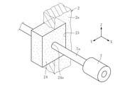
- the first transfer roller 7 is inserted into the furnace from the outside of the molding furnace 2 through the opening 23 provided in the side wall portion 2a of the molding furnace 2.
- the gap between the opening 23 and the shaft portion 7a of the first transport roller 7 is sealed with, for example, a first sealing member 24 made of refractory fiber.
- One end of the shaft portion 7a is held by a bearing (not shown) arranged outside the molding furnace 2.
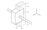
- the heater 15 in the furnace is arranged from the outside of the molding furnace 2 to the inside of the furnace through the opening 23 for the first transfer roller 7.
- the gap between the opening 23 and the heater 15 in the furnace is sealed with, for example, a second sealing member 25 made of refractory fiber.
- One end of the furnace heater 15 and the furnace thermometer 16 is held by a member arranged outside the molding furnace 2.
- the lower part of the molded body 3 is heated by the in-core heater 15 arranged in the molding furnace 2.
- the temperature of the lower part of the molded body 3 can be stabilized by the in-core heater 15 arranged near the lower part of the molded body 3. Damage such as cracking of the molded body 3 due to thermal impact can be reduced.
- the molded body 3 is also heated by the outside furnace heaters 17, 18, and 19 arranged outside the molding furnace 2.
- the temperature distribution in the molding furnace 2 can be appropriately adjusted.
- the temperature distribution in the molding furnace 2 is not particularly limited.
- the temperature near the ceiling portion 2b may be set to be higher than the temperature near the lower portion of the molded body 3, and the temperature near the ceiling portion 2b is the temperature near the lower portion of the molded body 3. It may be set to be lower than, and the temperature near the ceiling portion 2b may be set to be the same as the temperature near the lower part of the molded body 3.
- the heating temperature by the in-firer heater 15 and / or the out-of-firer heaters 17, 18 and 19 is adjusted based on the temperature measured by the in-firer thermometer 16 and / or the out-of-firer thermometer 20, 21 and 22.
- the temperature rising step shifts to the production process.
- shifting from the temperature raising process to the production process first, as shown in FIG. 7, the temperature inside the furnace is kept in a state where the heating of the molded body 3 by the heater 15 inside the furnace and the heaters 17, 18 and 19 outside the furnace is continued. A total of 16 is removed outside the furnace.
- the molten glass Gm is supplied to the groove 8 of the molded body 3 while the heating of the molded body 3 by the in-core heater 15 and the outside heaters 17, 18 and 19 is continued.
- each outer surface 10 of the molded body 3 is covered with the molten glass Gm overflowing from the groove 8.
- the molded body 3 is provided with the outside heaters 17, 18, and 19. While continuing the heating, the heater 15 in the furnace is retracted from the position where the lower portion of the molded body 3 is heated. In the present embodiment, the heater 15 in the furnace is removed to the outside of the furnace through the opening 23 of the molding furnace 2.
- the glass plate G to be a product is manufactured at the stage where a predetermined preparatory step such as arranging the first transfer roller 7 at a predetermined position in the furnace through the opening 23 of the molding furnace 2 is completed. Start to do. Also in the production process, it is preferable to control the temperature distribution in the molding furnace 2 by the heaters 17, 18 and 19 outside the furnace.
- the molded body 3 When the molten glass Gm is supplied to the molded body 3, the molded body 3 is covered with the high-temperature molten glass Gm, so that the temperature drop at the lower part of the molded body 3 is less likely to occur.
- the lower part of the molded body 3 is heated by the in-core heater 15 while the molded body 3 is covered with the high-temperature molten glass Gm, the molten glass Gm and / or the glass ribbon Gr is overheated, and the glass ribbon Gr is formed. It may be difficult to mold stably. Therefore, in the production process (molding process), it is preferable not to heat the heater 15 in the furnace.
- the heaters 15 in the furnace are arranged so as to form a pair by sandwiching both outer surfaces 10 of the lower portion of the molded body 3 from both sides in the thickness direction Y. ing. That is, the heater 15 in the furnace is arranged above the first embodiment.
- the heater 15 in the furnace is arranged in a state of being embedded in the lower part of the molded body 3. That is, the present invention is not limited to the case where the heater 15 in the furnace is arranged outside the molded body 3.
- the present invention is not limited to the configuration of the above embodiment, and is not limited to the above-mentioned action and effect.
- the present invention can be modified in various ways without departing from the gist of the present invention.
- the shapes of the in-firer heater 15 and the out-of-firer heaters 17, 18, and 19 are not particularly limited, and may be a rod-shaped heater or a planar heater. Further, the outside heaters 17, 18 and 19 may be omitted.
- the in-firer thermometer 16 may be arranged in the furnace through an opening 23 for arranging the first transfer roller 7 in the furnace.
- thermometer 16 in the furnace may be left in the molding furnace 2 in the production process as long as it does not hinder the transfer of the molten glass Gm and the glass ribbon Gr.
- the thermometer 16 in the furnace may be omitted in the temperature raising step and the production step.
- the heating temperature of the furnace heater 15 in the heating step can be adjusted based on, for example, the outside furnace thermometers 20, 21 and 22.
- both ends of the molded body 3 in the width direction may be pressed (pressurized) from both sides.
- the heating by the furnace heater 15 may be simply stopped without retracting the furnace heater 15.
- an opening for arranging the heater 15 in the furnace may be provided independently of the opening 23 for arranging the first transfer roller 7 in the furnace.
- the glass plate G is exemplified as the glass article, but the glass article is not limited to this.
- the glass article may be, for example, a glass roll in which a glass ribbon Gr is wound around a winding core in a roll shape.
Landscapes
- Chemical & Material Sciences (AREA)
- Engineering & Computer Science (AREA)
- Materials Engineering (AREA)
- Organic Chemistry (AREA)
- Re-Forming, After-Treatment, Cutting And Transporting Of Glass Products (AREA)
Abstract
Description
図1~図4に示すように、第一実施形態に係るガラス物品の製造方法は、ガラス物品の製造装置1を用いて、オーバーフローダウンドロー法によってガラス物品としてのガラス板Gを製造するものである。本製造方法は、成形炉2内に配置された成形体3を昇温する昇温工程(図3及び図4)と、昇温された成形体3に溶融ガラスGmを供給し、溶融ガラスGmからガラスリボンGrを成形する成形工程を含む生産工程(図1及び図2)とを備えている。
第二実施形態では、昇温工程における炉内ヒータ15の配置位置の変形例を例示する。図10に示すように、本実施形態では、昇温工程において、炉内ヒータ15が、成形体3の下部の両外側面10を、厚み方向Yで両側から挟んで対をなすように配置されている。つまり、炉内ヒータ15が、第一実施形態よりも上方に配置されている。
第三実施形態では、昇温工程における炉内ヒータ15の配置位置の変形例を例示する。図11に示すように、本実施形態では、昇温工程において、炉内ヒータ15が、成形体3の下部の内部に埋め込まれた状態で配置されている。つまり、本発明は、炉内ヒータ15を成形体3の外部に配置する場合に限定されない。
2 成形炉
3 成形体
4 徐冷炉
5 冷却室
6 切断室
7 第一搬送ローラ(エッジローラ)
13 第二搬送ローラ(アニーラローラ)
14 第三搬送ローラ
15 炉内ヒータ
16 炉内温度計
17 第一炉外ヒータ
18 第二炉外ヒータ
19 第三炉外ヒータ
20 第一炉外温度計
21 第二炉外温度計
22 第三炉外温度計
23 開口部
G ガラス板
Gm 溶融ガラス
Gr ガラスリボン
Claims (7)
- オーバーフローダウンドロー法によるガラス物品の製造方法において、
成形炉内に配置された成形体を昇温する昇温工程と、
昇温された前記成形体に溶融ガラスを供給し、前記溶融ガラスからガラスリボンを成形する成形工程とを備え、
前記昇温工程では、前記成形炉内に配置された炉内ヒータにより、前記成形体の下部を加熱することを特徴とするガラス物品の製造方法。 - 前記成形体に前記溶融ガラスを供給した後、前記炉内ヒータによる前記成形体の下部の加熱を低下又は停止する請求項1に記載のガラス物品の製造方法。
- 前記成形体に前記溶融ガラスを供給した後、前記炉内ヒータを前記成形体の下部を加熱する位置から退避させる請求項2に記載のガラス物品の製造方法。
- 前記炉内ヒータは、前記ガラスリボンの厚み方向における前記成形体の下部の両外側面、又は前記成形体の下部よりも下方における前記ガラスリボンの通過部を、前記厚み方向で両側から挟んで対をなすように配置される請求項1~3のいずれか1項に記載のガラス部品の製造方法。
- 前記炉内ヒータは、前記成形炉の側壁部に設けられた前記ガラスリボンの搬送ローラ用の開口部を通じて、前記成形炉内に配置される請求項1~4のいずれか1項に記載のガラス物品の製造方法。
- 前記昇温工程では、前記成形体の下部の温度を測定する温度計が、前記成形炉内に配置される請求項1~5のいずれか1項に記載のガラス物品の製造方法。
- 前記成形炉外には、前記成形炉の側壁部の上部に対応する位置に前記成形体の上部を加熱する第一炉外ヒータが配置され、前記成形炉の側壁部の下部に対応する位置に前記成形体の下部を加熱する第二炉外ヒータが配置され、前記成形炉の天井部に対応する位置に前記成形体の上部を加熱する第三炉外ヒータが配置されており、
前記昇温工程では、前記第一炉外ヒータ、前記第二炉外ヒータ及び前記第三炉外ヒータにより、前記成形体をさらに加熱する請求項1~6のいずれか1項に記載のガラス物品の製造方法。
Priority Applications (2)
| Application Number | Priority Date | Filing Date | Title |
|---|---|---|---|
| CN202180046815.1A CN115768732B (zh) | 2020-07-16 | 2021-06-23 | 玻璃物品的制造方法 |
| KR1020237003150A KR102822675B1 (ko) | 2020-07-16 | 2021-06-23 | 유리 물품의 제조 방법 |
Applications Claiming Priority (2)
| Application Number | Priority Date | Filing Date | Title |
|---|---|---|---|
| JP2020122189A JP7495662B2 (ja) | 2020-07-16 | 2020-07-16 | ガラス物品の製造方法 |
| JP2020-122189 | 2020-07-16 |
Publications (1)
| Publication Number | Publication Date |
|---|---|
| WO2022014288A1 true WO2022014288A1 (ja) | 2022-01-20 |
Family
ID=79555235
Family Applications (1)
| Application Number | Title | Priority Date | Filing Date |
|---|---|---|---|
| PCT/JP2021/023864 Ceased WO2022014288A1 (ja) | 2020-07-16 | 2021-06-23 | ガラス物品の製造方法 |
Country Status (4)
| Country | Link |
|---|---|
| JP (1) | JP7495662B2 (ja) |
| KR (1) | KR102822675B1 (ja) |
| CN (1) | CN115768732B (ja) |
| WO (1) | WO2022014288A1 (ja) |
Citations (8)
| Publication number | Priority date | Publication date | Assignee | Title |
|---|---|---|---|---|
| WO2011007617A1 (ja) * | 2009-07-13 | 2011-01-20 | 旭硝子株式会社 | ガラス板の製造方法及び製造装置 |
| WO2011122195A1 (ja) * | 2010-03-30 | 2011-10-06 | 日本電気硝子株式会社 | 薄板ガラスおよびその製造方法 |
| WO2012132309A1 (ja) * | 2011-03-28 | 2012-10-04 | AvanStrate株式会社 | ガラス板の製造方法及びガラス板製造装置 |
| JP2013079156A (ja) * | 2011-09-30 | 2013-05-02 | Avanstrate Inc | ガラス板の製造方法 |
| JP2015027947A (ja) * | 2009-11-30 | 2015-02-12 | コーニング インコーポレイテッド | ガラスシート製造時の加熱を制御する方法および装置 |
| WO2017110212A1 (ja) * | 2015-12-22 | 2017-06-29 | 日本電気硝子株式会社 | 板ガラス製造装置及び板ガラス製造方法 |
| JP2019026489A (ja) * | 2017-07-26 | 2019-02-21 | 日本電気硝子株式会社 | ガラス物品の製造方法及び製造装置 |
| WO2020049944A1 (ja) * | 2018-09-03 | 2020-03-12 | 日本電気硝子株式会社 | ガラス物品の製造方法及び製造装置 |
Family Cites Families (7)
| Publication number | Priority date | Publication date | Assignee | Title |
|---|---|---|---|---|
| WO2008050605A1 (fr) * | 2006-10-24 | 2008-05-02 | Nippon Electric Glass Co., Ltd. | Appareil de production de rubans de verre et procédé de production associé |
| JP5428288B2 (ja) * | 2007-12-25 | 2014-02-26 | 日本電気硝子株式会社 | ガラス板の製造方法及び製造設備 |
| JP5724552B2 (ja) | 2011-04-01 | 2015-05-27 | 日本電気硝子株式会社 | 薄板ガラス製造装置 |
| JP2012167014A (ja) * | 2012-05-11 | 2012-09-06 | Nippon Electric Glass Co Ltd | ガラス板の製造方法及び製造設備 |
| JP6270636B2 (ja) * | 2014-06-06 | 2018-01-31 | 川崎重工業株式会社 | ガラス板分離装置 |
| CN109803933A (zh) * | 2016-09-29 | 2019-05-24 | 康宁股份有限公司 | 用于玻璃带热管理的方法和设备 |
| JP6708968B2 (ja) * | 2016-11-11 | 2020-06-10 | 日本電気硝子株式会社 | 板ガラス製造装置及び板ガラス製造方法 |
-
2020
- 2020-07-16 JP JP2020122189A patent/JP7495662B2/ja active Active
-
2021
- 2021-06-23 CN CN202180046815.1A patent/CN115768732B/zh active Active
- 2021-06-23 KR KR1020237003150A patent/KR102822675B1/ko active Active
- 2021-06-23 WO PCT/JP2021/023864 patent/WO2022014288A1/ja not_active Ceased
Patent Citations (8)
| Publication number | Priority date | Publication date | Assignee | Title |
|---|---|---|---|---|
| WO2011007617A1 (ja) * | 2009-07-13 | 2011-01-20 | 旭硝子株式会社 | ガラス板の製造方法及び製造装置 |
| JP2015027947A (ja) * | 2009-11-30 | 2015-02-12 | コーニング インコーポレイテッド | ガラスシート製造時の加熱を制御する方法および装置 |
| WO2011122195A1 (ja) * | 2010-03-30 | 2011-10-06 | 日本電気硝子株式会社 | 薄板ガラスおよびその製造方法 |
| WO2012132309A1 (ja) * | 2011-03-28 | 2012-10-04 | AvanStrate株式会社 | ガラス板の製造方法及びガラス板製造装置 |
| JP2013079156A (ja) * | 2011-09-30 | 2013-05-02 | Avanstrate Inc | ガラス板の製造方法 |
| WO2017110212A1 (ja) * | 2015-12-22 | 2017-06-29 | 日本電気硝子株式会社 | 板ガラス製造装置及び板ガラス製造方法 |
| JP2019026489A (ja) * | 2017-07-26 | 2019-02-21 | 日本電気硝子株式会社 | ガラス物品の製造方法及び製造装置 |
| WO2020049944A1 (ja) * | 2018-09-03 | 2020-03-12 | 日本電気硝子株式会社 | ガラス物品の製造方法及び製造装置 |
Also Published As
| Publication number | Publication date |
|---|---|
| KR20230041714A (ko) | 2023-03-24 |
| JP2022018816A (ja) | 2022-01-27 |
| CN115768732A (zh) | 2023-03-07 |
| KR102822675B1 (ko) | 2025-06-20 |
| CN115768732B (zh) | 2025-02-07 |
| JP7495662B2 (ja) | 2024-06-05 |
Similar Documents
| Publication | Publication Date | Title |
|---|---|---|
| TWI557082B (zh) | Plate glass forming method and forming mold | |
| CN102471121B (zh) | 玻璃板的制造方法及制造装置 | |
| JP3586142B2 (ja) | ガラス板の製造方法、ガラス板の製造装置、及び液晶デバイス | |
| TWI625310B (zh) | 形成成型玻璃物件之方法以及系統 | |
| KR102938284B1 (ko) | 유리 물품의 제조 방법 | |
| CN102958854B (zh) | 玻璃成形用的成形模具、玻璃成形装置、玻璃成形方法及光罩基板的制造方法 | |
| TWI577646B (zh) | A manufacturing method of a glass plate, and a manufacturing apparatus for a glass plate | |
| JP2004345916A (ja) | ガラス物品の徐冷方法、ガラス物品の加熱方法、ガラス成形品の製造方法、及び熱処理装置 | |
| JP2022018816A (ja) | ガラス物品の製造方法 | |
| JP5619935B2 (ja) | 薄板ガラス製造方法および薄板ガラス製造装置 | |
| JP7853037B2 (ja) | 全体厚さばらつきを低減したガラス板の製造方法 | |
| JP2025130028A (ja) | ガラス物品の製造方法 | |
| JP7828558B2 (ja) | ガラス物品の製造装置 | |
| CN107352780B (zh) | 一种玻璃加工装置及加工方法 | |
| CN222923046U (zh) | 玻璃物品的制造装置 | |
| JP6082434B2 (ja) | ガラス基板の製造方法及びガラス基板 | |
| JP7498893B2 (ja) | ガラス物品の製造方法及び製造装置 | |
| JP2026064419A (ja) | 成形体及びガラス物品の製造方法 | |
| JP7488509B2 (ja) | ガラス物品の製造装置及びその製造方法 | |
| JP2025149896A (ja) | ガラス物品の製造方法 | |
| TWI580650B (zh) | Glass substrate manufacturing method and glass substrate | |
| WO2025052964A1 (ja) | ガラス板及びその製造方法 | |
| JP2024080064A (ja) | ガラス物品の製造方法 | |
| JP2014047973A (ja) | 熱処理用セッター及びそれを用いた熱処理方法 | |
| JP2016124746A (ja) | ガラス基板の製造方法、及び、ガラス基板の製造装置 |
Legal Events
| Date | Code | Title | Description |
|---|---|---|---|
| 121 | Ep: the epo has been informed by wipo that ep was designated in this application |
Ref document number: 21843521 Country of ref document: EP Kind code of ref document: A1 |
|
| ENP | Entry into the national phase |
Ref document number: 20237003150 Country of ref document: KR Kind code of ref document: A |
|
| NENP | Non-entry into the national phase |
Ref country code: DE |
|
| 122 | Ep: pct application non-entry in european phase |
Ref document number: 21843521 Country of ref document: EP Kind code of ref document: A1 |
|
| WWG | Wipo information: grant in national office |
Ref document number: 202180046815.1 Country of ref document: CN |