WO2022014221A1 - 超純水製造装置 - Google Patents
超純水製造装置 Download PDFInfo
- Publication number
- WO2022014221A1 WO2022014221A1 PCT/JP2021/022283 JP2021022283W WO2022014221A1 WO 2022014221 A1 WO2022014221 A1 WO 2022014221A1 JP 2021022283 W JP2021022283 W JP 2021022283W WO 2022014221 A1 WO2022014221 A1 WO 2022014221A1
- Authority
- WO
- WIPO (PCT)
- Prior art keywords
- ultrafiltration membrane
- concentrated water
- water
- flow rate
- ultrapure water
- Prior art date
- Legal status (The legal status is an assumption and is not a legal conclusion. Google has not performed a legal analysis and makes no representation as to the accuracy of the status listed.)
- Ceased
Links
Images




Classifications
-
- C—CHEMISTRY; METALLURGY
- C02—TREATMENT OF WATER, WASTE WATER, SEWAGE, OR SLUDGE
- C02F—TREATMENT OF WATER, WASTE WATER, SEWAGE, OR SLUDGE
- C02F9/00—Multistage treatment of water, waste water or sewage
-
- B—PERFORMING OPERATIONS; TRANSPORTING
- B01—PHYSICAL OR CHEMICAL PROCESSES OR APPARATUS IN GENERAL
- B01D—SEPARATION
- B01D61/00—Processes of separation using semi-permeable membranes, e.g. dialysis, osmosis or ultrafiltration; Apparatus, accessories or auxiliary operations specially adapted therefor
- B01D61/14—Ultrafiltration; Microfiltration
- B01D61/145—Ultrafiltration
- B01D61/146—Ultrafiltration comprising multiple ultrafiltration steps
-
- B—PERFORMING OPERATIONS; TRANSPORTING
- B01—PHYSICAL OR CHEMICAL PROCESSES OR APPARATUS IN GENERAL
- B01D—SEPARATION
- B01D61/00—Processes of separation using semi-permeable membranes, e.g. dialysis, osmosis or ultrafiltration; Apparatus, accessories or auxiliary operations specially adapted therefor
- B01D61/14—Ultrafiltration; Microfiltration
- B01D61/18—Apparatus therefor
-
- B—PERFORMING OPERATIONS; TRANSPORTING
- B01—PHYSICAL OR CHEMICAL PROCESSES OR APPARATUS IN GENERAL
- B01D—SEPARATION
- B01D61/00—Processes of separation using semi-permeable membranes, e.g. dialysis, osmosis or ultrafiltration; Apparatus, accessories or auxiliary operations specially adapted therefor
- B01D61/14—Ultrafiltration; Microfiltration
- B01D61/22—Controlling or regulating
-
- B—PERFORMING OPERATIONS; TRANSPORTING
- B01—PHYSICAL OR CHEMICAL PROCESSES OR APPARATUS IN GENERAL
- B01D—SEPARATION
- B01D61/00—Processes of separation using semi-permeable membranes, e.g. dialysis, osmosis or ultrafiltration; Apparatus, accessories or auxiliary operations specially adapted therefor
- B01D61/58—Multistep processes
-
- C—CHEMISTRY; METALLURGY
- C02—TREATMENT OF WATER, WASTE WATER, SEWAGE, OR SLUDGE
- C02F—TREATMENT OF WATER, WASTE WATER, SEWAGE, OR SLUDGE
- C02F1/00—Treatment of water, waste water, or sewage
- C02F1/008—Control or steering systems not provided for elsewhere in subclass C02F
-
- B—PERFORMING OPERATIONS; TRANSPORTING
- B01—PHYSICAL OR CHEMICAL PROCESSES OR APPARATUS IN GENERAL
- B01D—SEPARATION
- B01D2311/00—Details relating to membrane separation process operations and control
- B01D2311/14—Pressure control
-
- B—PERFORMING OPERATIONS; TRANSPORTING
- B01—PHYSICAL OR CHEMICAL PROCESSES OR APPARATUS IN GENERAL
- B01D—SEPARATION
- B01D2311/00—Details relating to membrane separation process operations and control
- B01D2311/16—Flow or flux control
-
- B—PERFORMING OPERATIONS; TRANSPORTING
- B01—PHYSICAL OR CHEMICAL PROCESSES OR APPARATUS IN GENERAL
- B01D—SEPARATION
- B01D2311/00—Details relating to membrane separation process operations and control
- B01D2311/24—Quality control
-
- B—PERFORMING OPERATIONS; TRANSPORTING
- B01—PHYSICAL OR CHEMICAL PROCESSES OR APPARATUS IN GENERAL
- B01D—SEPARATION
- B01D2311/00—Details relating to membrane separation process operations and control
- B01D2311/25—Recirculation, recycling or bypass, e.g. recirculation of concentrate into the feed
-
- B—PERFORMING OPERATIONS; TRANSPORTING
- B01—PHYSICAL OR CHEMICAL PROCESSES OR APPARATUS IN GENERAL
- B01D—SEPARATION
- B01D2311/00—Details relating to membrane separation process operations and control
- B01D2311/25—Recirculation, recycling or bypass, e.g. recirculation of concentrate into the feed
- B01D2311/251—Recirculation of permeate
- B01D2311/2512—Recirculation of permeate to feed side
-
- B—PERFORMING OPERATIONS; TRANSPORTING
- B01—PHYSICAL OR CHEMICAL PROCESSES OR APPARATUS IN GENERAL
- B01D—SEPARATION
- B01D2313/00—Details relating to membrane modules or apparatus
- B01D2313/08—Flow guidance means within the module or the apparatus
- B01D2313/083—Bypass routes
-
- B—PERFORMING OPERATIONS; TRANSPORTING
- B01—PHYSICAL OR CHEMICAL PROCESSES OR APPARATUS IN GENERAL
- B01D—SEPARATION
- B01D2313/00—Details relating to membrane modules or apparatus
- B01D2313/18—Specific valves
-
- B—PERFORMING OPERATIONS; TRANSPORTING
- B01—PHYSICAL OR CHEMICAL PROCESSES OR APPARATUS IN GENERAL
- B01D—SEPARATION
- B01D2313/00—Details relating to membrane modules or apparatus
- B01D2313/24—Specific pressurizing or depressurizing means
- B01D2313/243—Pumps
-
- B—PERFORMING OPERATIONS; TRANSPORTING
- B01—PHYSICAL OR CHEMICAL PROCESSES OR APPARATUS IN GENERAL
- B01D—SEPARATION
- B01D2313/00—Details relating to membrane modules or apparatus
- B01D2313/90—Additional auxiliary systems integrated with the module or apparatus
- B01D2313/903—Integrated control or detection device
-
- B—PERFORMING OPERATIONS; TRANSPORTING
- B01—PHYSICAL OR CHEMICAL PROCESSES OR APPARATUS IN GENERAL
- B01D—SEPARATION
- B01D2317/00—Membrane module arrangements within a plant or an apparatus
- B01D2317/02—Elements in series
- B01D2317/022—Reject series
-
- B—PERFORMING OPERATIONS; TRANSPORTING
- B01—PHYSICAL OR CHEMICAL PROCESSES OR APPARATUS IN GENERAL
- B01D—SEPARATION
- B01D2317/00—Membrane module arrangements within a plant or an apparatus
- B01D2317/04—Elements in parallel
-
- B—PERFORMING OPERATIONS; TRANSPORTING
- B01—PHYSICAL OR CHEMICAL PROCESSES OR APPARATUS IN GENERAL
- B01D—SEPARATION
- B01D2317/00—Membrane module arrangements within a plant or an apparatus
- B01D2317/06—Use of membrane modules of the same kind
-
- B—PERFORMING OPERATIONS; TRANSPORTING
- B01—PHYSICAL OR CHEMICAL PROCESSES OR APPARATUS IN GENERAL
- B01D—SEPARATION
- B01D61/00—Processes of separation using semi-permeable membranes, e.g. dialysis, osmosis or ultrafiltration; Apparatus, accessories or auxiliary operations specially adapted therefor
- B01D61/02—Reverse osmosis; Hyperfiltration ; Nanofiltration
- B01D61/025—Reverse osmosis; Hyperfiltration
-
- C—CHEMISTRY; METALLURGY
- C02—TREATMENT OF WATER, WASTE WATER, SEWAGE, OR SLUDGE
- C02F—TREATMENT OF WATER, WASTE WATER, SEWAGE, OR SLUDGE
- C02F1/00—Treatment of water, waste water, or sewage
- C02F1/001—Processes for the treatment of water whereby the filtration technique is of importance
-
- C—CHEMISTRY; METALLURGY
- C02—TREATMENT OF WATER, WASTE WATER, SEWAGE, OR SLUDGE
- C02F—TREATMENT OF WATER, WASTE WATER, SEWAGE, OR SLUDGE
- C02F1/00—Treatment of water, waste water, or sewage
- C02F1/20—Treatment of water, waste water, or sewage by degassing, i.e. liberation of dissolved gases
-
- C—CHEMISTRY; METALLURGY
- C02—TREATMENT OF WATER, WASTE WATER, SEWAGE, OR SLUDGE
- C02F—TREATMENT OF WATER, WASTE WATER, SEWAGE, OR SLUDGE
- C02F1/00—Treatment of water, waste water, or sewage
- C02F1/30—Treatment of water, waste water, or sewage by irradiation
- C02F1/32—Treatment of water, waste water, or sewage by irradiation with ultraviolet light
-
- C—CHEMISTRY; METALLURGY
- C02—TREATMENT OF WATER, WASTE WATER, SEWAGE, OR SLUDGE
- C02F—TREATMENT OF WATER, WASTE WATER, SEWAGE, OR SLUDGE
- C02F1/00—Treatment of water, waste water, or sewage
- C02F1/42—Treatment of water, waste water, or sewage by ion-exchange
-
- C—CHEMISTRY; METALLURGY
- C02—TREATMENT OF WATER, WASTE WATER, SEWAGE, OR SLUDGE
- C02F—TREATMENT OF WATER, WASTE WATER, SEWAGE, OR SLUDGE
- C02F1/00—Treatment of water, waste water, or sewage
- C02F1/44—Treatment of water, waste water, or sewage by dialysis, osmosis or reverse osmosis
- C02F1/444—Treatment of water, waste water, or sewage by dialysis, osmosis or reverse osmosis by ultrafiltration or microfiltration
-
- C—CHEMISTRY; METALLURGY
- C02—TREATMENT OF WATER, WASTE WATER, SEWAGE, OR SLUDGE
- C02F—TREATMENT OF WATER, WASTE WATER, SEWAGE, OR SLUDGE
- C02F2103/00—Nature of the water, waste water, sewage or sludge to be treated
- C02F2103/02—Non-contaminated water, e.g. for industrial water supply
- C02F2103/04—Non-contaminated water, e.g. for industrial water supply for obtaining ultra-pure water
-
- C—CHEMISTRY; METALLURGY
- C02—TREATMENT OF WATER, WASTE WATER, SEWAGE, OR SLUDGE
- C02F—TREATMENT OF WATER, WASTE WATER, SEWAGE, OR SLUDGE
- C02F2201/00—Apparatus for treatment of water, waste water or sewage
- C02F2201/002—Construction details of the apparatus
- C02F2201/005—Valves
-
- C—CHEMISTRY; METALLURGY
- C02—TREATMENT OF WATER, WASTE WATER, SEWAGE, OR SLUDGE
- C02F—TREATMENT OF WATER, WASTE WATER, SEWAGE, OR SLUDGE
- C02F2209/00—Controlling or monitoring parameters in water treatment
- C02F2209/005—Processes using a programmable logic controller [PLC]
- C02F2209/006—Processes using a programmable logic controller [PLC] comprising a software program or a logic diagram
-
- C—CHEMISTRY; METALLURGY
- C02—TREATMENT OF WATER, WASTE WATER, SEWAGE, OR SLUDGE
- C02F—TREATMENT OF WATER, WASTE WATER, SEWAGE, OR SLUDGE
- C02F2209/00—Controlling or monitoring parameters in water treatment
- C02F2209/03—Pressure
-
- C—CHEMISTRY; METALLURGY
- C02—TREATMENT OF WATER, WASTE WATER, SEWAGE, OR SLUDGE
- C02F—TREATMENT OF WATER, WASTE WATER, SEWAGE, OR SLUDGE
- C02F2209/00—Controlling or monitoring parameters in water treatment
- C02F2209/05—Conductivity or salinity
-
- C—CHEMISTRY; METALLURGY
- C02—TREATMENT OF WATER, WASTE WATER, SEWAGE, OR SLUDGE
- C02F—TREATMENT OF WATER, WASTE WATER, SEWAGE, OR SLUDGE
- C02F2209/00—Controlling or monitoring parameters in water treatment
- C02F2209/22—O2
-
- C—CHEMISTRY; METALLURGY
- C02—TREATMENT OF WATER, WASTE WATER, SEWAGE, OR SLUDGE
- C02F—TREATMENT OF WATER, WASTE WATER, SEWAGE, OR SLUDGE
- C02F2209/00—Controlling or monitoring parameters in water treatment
- C02F2209/40—Liquid flow rate
-
- C—CHEMISTRY; METALLURGY
- C02—TREATMENT OF WATER, WASTE WATER, SEWAGE, OR SLUDGE
- C02F—TREATMENT OF WATER, WASTE WATER, SEWAGE, OR SLUDGE
- C02F2301/00—General aspects of water treatment
- C02F2301/04—Flow arrangements
- C02F2301/046—Recirculation with an external loop
-
- C—CHEMISTRY; METALLURGY
- C02—TREATMENT OF WATER, WASTE WATER, SEWAGE, OR SLUDGE
- C02F—TREATMENT OF WATER, WASTE WATER, SEWAGE, OR SLUDGE
- C02F2301/00—General aspects of water treatment
- C02F2301/08—Multistage treatments, e.g. repetition of the same process step under different conditions
Definitions
- the present invention relates to an ultrapure water production apparatus, and particularly to a configuration of a subsystem that produces ultrapure water from pure water.
- ultrapure water with highly removed impurities is used for various purposes such as cleaning processes.
- Ultrapure water is generally produced by sequentially treating raw water (river water, groundwater, industrial water, etc.) with a pretreatment system, a primary pure water system, and a secondary pure water system (subsystem). Since the fine particles contained in ultrapure water directly cause a decrease in the yield of the device, their size (particle size) and number (concentration) are strictly controlled. Therefore, in order to reduce the number of fine particles in ultrapure water, a subsystem in which an ultrafiltration membrane is arranged in the final stage has been proposed (see International Publication No. 2017/145419).
- the ultrafiltration membrane does not allow the entire amount to permeate, but a part of the concentrated water is returned to the upstream side.
- the flow rate of concentrated water returned to the upstream side is determined by the required water quality, etc., but in order to reduce the water production cost, it is desirable to suppress the flow rate of concentrated water as much as possible. Therefore, the flow rate of concentrated water may be changed while monitoring the water quality during operation.
- This work involves fluctuations in the pressure of the water to be treated, especially the inlet and outlet pressures of the ultrafiltration membrane.
- International Publication No. 2017/145419 it is known that the fine particles adhering to the inner wall of the pipe are peeled off due to the fluctuation of the pressure. Therefore, according to the technique described in International Publication No.
- fine particles adhering to the pipe are removed by supplying ultrapure water at a high pressure.
- the ultrafiltration membrane is removed and a dummy tube or a dummy membrane having no function of the ultrafiltration membrane is installed.
- Japanese Patent No. 6670206 discloses that fine particles are separated from the ultrafiltration membrane during the operation of the ultrapure water production apparatus, which affects the water quality of the ultrapure water. Therefore, the method disclosed in Patent Document 1 cannot suppress the generation of fine particles from the ultrafiltration membrane during operation. In addition, ultrapure water cannot be produced during the high-pressure cleaning process, and it is necessary to remove the ultrafiltration membrane before and after cleaning, which leads to a decrease in the operating rate of the ultrapure water production equipment.
- An object of the present invention is to provide an ultrapure water production apparatus capable of reducing the cost of water production and suppressing the generation of fine particles from the ultrafiltration membrane during operation with a simple configuration.
- the ultrapure water production apparatus of the present invention is connected to a point of use and supplies ultrapure water to the point of use. It has a first concentrated water return line for returning to the upstream of the filtration membrane, a pressure gauge for measuring the outlet pressure of the first ultrafiltration membrane, and a concentrated water flow rate adjusting means for adjusting the flow rate of the concentrated water. ing.
- the concentrated water flow rate adjusting means can be operated so that the fluctuation of the outlet pressure of the first ultrafiltration membrane measured by the pressure gauge when the flow rate of the concentrated water changes is within a predetermined range.
- an ultrapure water production apparatus capable of suppressing the generation of fine particles from the ultrafiltration membrane during operation with a simple configuration.
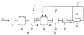
- FIG. 1 shows a schematic configuration of an ultrapure water production apparatus 1 according to a first embodiment of the present invention.
- the ultrapure water production apparatus 1 includes a pretreatment system 11 that treats raw water to produce primary treated water, a primary pure water system 21 that produces pure water from the primary treated water produced by the pretreatment system 11, and a primary. It has a secondary pure water system 31 (hereinafter referred to as subsystem 31) that produces ultrapure water from pure water produced by the pure water system 21.
- the primary pure water system 21 includes a purification unit 23 including a reverse osmosis membrane (not shown), an ultraviolet oxidizing device, a microfiltration membrane, etc., in addition to the primary treated water tank 22 for storing the primary treated water, and is pure through the pure water supply line L1. Water is supplied to the sub tank 32 of the subsystem 31.
- a purification unit 23 including a reverse osmosis membrane (not shown), an ultraviolet oxidizing device, a microfiltration membrane, etc.
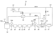
- FIG. 2 shows a schematic configuration of the subsystem 31 shown in FIG.
- the subsystem 31 includes a sub tank 32, a first pump 33, an ultraviolet oxidizing device 34, a hydrogen peroxide removing device 35, an ion exchange device 36, a membrane degassing device 37, a second pump 38, and a first ultrafiltration membrane. 39 are arranged in this order.
- the ultraviolet oxidizing device 34, the hydrogen peroxide removing device 35, the ion exchange device 36, the membrane degassing device 37, and the first ultrafiltration membrane 39 constitute a purification unit for the water to be treated.
- the first pump 33 is an AC motor, and the flow rate is controlled by the first inverter 33A.
- the second pump 38 is an AC motor, and the flow rate is controlled by the second inverter 38A.
- the ultraviolet oxidizing device 34 irradiates the water to be treated with ultraviolet rays to decompose organic substances contained in the water to be treated.
- the hydrogen peroxide removing device 35 includes a catalyst such as palladium (Pd) or platinum (Pt), and decomposes hydrogen peroxide generated by irradiation with ultraviolet rays. This prevents the ion exchange device 36 in the subsequent stage from being damaged by the oxidizing substance.
- the ion exchange device 36 is filled with a cation exchange resin and an anion exchange resin in a mixed bed, and removes ion components in the water to be treated.
- the membrane deaerator 37 removes dissolved oxygen and carbon dioxide contained in the water to be treated.
- the first ultrafiltration membrane 39 is a purification unit in the final stage of the subsystem 31 and removes fine particles remaining in the water to be treated.
- the first ultrafiltration membrane 39 is connected to the use point 51 and supplies ultrapure water to the use point 51.
- the purification unit excluding the first ultrafiltration membrane 39 is displayed as the pre-stage purification unit 41.
- the particle counter PC1 (first particle measuring means) is installed. Between the first ultrafiltration membrane 39 and the use point 51, a second particle for measuring fine particles (or the number of fine particles for each particle size) of the water to be treated at the outlet of the first ultrafiltration membrane 39.
- a counter PC2 (second fine particle measuring means) is installed. Only one of the first particle counter PC1 and the second particle counter PC2 can be provided, and in that case, it is preferable to provide the second particle counter PC2.
- a pressure gauge PI for measuring the outlet pressure of the first ultrafiltration membrane 39 is provided between the first ultrafiltration membrane 39 and the use point 51.
- the pressure gauge PI is provided downstream of the second particle counter PC2, it may be provided upstream of the second particle counter PC2.
- the concentrated water generated on the primary side (the side to which the water to be treated is supplied) of the first ultrafiltration membrane 39 is returned upstream of the first ultrafiltration membrane 39 by the first concentrated water return line L3. Will be done.
- the first concentrated water return line L3 is provided with a first valve V1 that functions as a concentrated water flow rate adjusting means.
- the return destination of the concentrated water is not particularly limited as long as it is upstream of the first ultrafiltration membrane 39, but in the present embodiment, the sub tank 32 is used. Depending on the quality of the concentrated water and the like, the concentrated water may be returned to the primary treatment water tank 22.
- the concentrated water is treated again by the primary pure water system 21, so that deterioration of the water quality of the ultrapure water supplied to the use point 51 can be suppressed and the water treatment load of the subsystem 31 can be reduced.
- the processing capacity of the primary pure water system 21 needs to be determined based on the total flow rate of the primary treated water supplied from the pretreatment system 11 and the returned concentrated water flow rate.
- the processing capacity of the primary pure water system 21 has increased, the design specifications of each device of the primary pure water system have become larger (the amount of resin and the number of films have increased), and the water production cost (power consumption, chemical usage, etc.) has increased. Leads to.
- the processing capacity of the primary pure water system 21 is determined by the flow rate of the primary treated water supplied from the pretreatment system 11, so that each device of the primary pure water system should be designed in a compact size. The impact on water production costs can be suppressed.
- the ultrapure water that was not used at the use point 51 is returned to the sub tank 32 by the return line L4, processed again by the subsystem 31, and supplied to the use point 51.
- a bypass line L5 branching from the main line L2 is provided between the first ultrafiltration membrane 39 and the use point 51.
- the bypass line L5 joins the return line L4, and the ultrapure water bypassing the use point 51 is returned to the sub tank 32 through the return line L4. Therefore, the bypass line L5 and the return line L4 return the ultrapure water that has passed through the first ultrafiltration membrane 39 to the upstream of the first ultrafiltration membrane 39, bypassing the use point 51.
- a second valve V2 is provided on the bypass line L5.
- the flow rate of the concentrated water returned from the first ultrafiltration membrane 39 to the upstream of the first ultrafiltration membrane 39, in the present embodiment, to the sub tank 32 is generally supplied to the first ultrafiltration membrane 39. Although it is about a few percent of the treated water, when the flow rate of the concentrated water increases, the flow rate of the ultrapure water supplied to the use point 51 decreases. Therefore, in order to reduce the water production cost, it is desirable to suppress the flow rate of concentrated water as much as possible. Therefore, in the present embodiment, when the number of fine particles measured by the first and second particle counters PC1 and PC2 is at a level at which there is no problem in the water quality of ultrapure water, that is, the fine particles required at use point 51.
- the first valve V1 which is the flow control valve for the concentrated water is throttled to reduce the flow rate of the concentrated water.
- the pressure of the main line L2 fluctuates while repeatedly increasing and decreasing. As a result, the fine particles are likely to be exfoliated from the first ultrafiltration membrane 39, and the water quality of the ultrapure water supplied to the use point 51 may be deteriorated.
- the first valve V1 is the first valve V1 measured by the pressure gauge PI when the flow rate of the concentrated water changes. It can be operated so that the fluctuation of the outlet pressure of the ultrafiltration membrane 39 is within a predetermined range.
- the predetermined range depends on the required specifications at the use point 51, but in one example, it is within 0.02 MPa, preferably within 0.01 MPa. Alternatively, the predetermined range may be within about 5%, preferably about 3% or less of the operating inlet pressure of the first ultrafiltration membrane 39.
- the first valve V1 and the pressure gauge PI are connected to the control unit 40, and the operation of the first valve V1, specifically, according to the outlet pressure of the first ultrafiltration membrane 39 measured by the pressure gauge PI.
- the opening degree and opening / closing speed of the first valve V1 are controlled by the control unit 40.
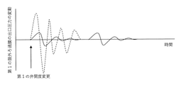
- FIG. 3 schematically shows the temporal change of the outlet pressure (measured value of the pressure gauge PI) of the first ultrafiltration membrane 39. For example, when the first valve V1 is changed from a predetermined opening to a different opening at a general speed (change amount of opening per hour), the first ultrafiltration membrane is shown by a broken line.
- the outlet pressure of 39 fluctuates greatly.
- the control unit 40 it is preferable to control the output of the second pump 38 by the control unit 40.
- the opening degree of the first valve V1 the pressure loss of the first ultrafiltration membrane 39 changes and the pressure of the main line L2 fluctuates.
- the main line L2 can be maintained at the same pressure.
- fluctuations in the outlet pressure of the first ultrafiltration membrane 39 are further suppressed. That is, by controlling the output of the second pump 38, the fluctuation of the outlet pressure of the first ultrafiltration membrane 39 can be suppressed more effectively than in the case of controlling only the first valve V1. Can be done.
- the control unit 40 is connected to the second inverter 38A of the second pump 38, and the second inverter 38A is controlled so that the fluctuation of the outlet pressure of the first ultrafiltration membrane 39 is within a predetermined range.
- the control unit 40 controls the second inverter 38A so that the pump rotation speed decreases when the pressure measured by the pressure gauge PI increases, whereby the first ultrafiltration membrane 39 Reduce the outlet pressure of.
- the control unit 40 controls the second inverter 38A so that the pump rotation speed increases when the pressure measured by the pressure gauge PI decreases, thereby increasing the outlet pressure of the first ultrafiltration membrane 39. Let me.
- the control of the first valve V1 and the second inverter 38A is performed in conjunction with the fluctuation of the pressure measured by the pressure gauge PI.
- the first valve V1 can be manually operated, it is preferable that the operation of the first valve V1 and the control of the second inverter 38A are automatically controlled by the control unit 40.
- the control unit 40 By controlling the second pump 38 located immediately upstream of the first ultrafiltration membrane 39, it is possible to more accurately control the outlet pressure of the first ultrafiltration membrane 39.
- the first pump 33 first inverter 33A
- both the first pump 33 and the second pump 38 may be controlled.
- FIG. 4 shows a schematic configuration of the subsystem 31 of the pure water production apparatus according to the second embodiment.
- the opening degree of the second valve V2 is controlled instead of the second pump 38.
- the first valve V1, the second valve V2, and the pressure gauge PI are connected to the control unit 40, and the opening degrees of the first valve V1 and the second valve V2 are adjusted according to the measured values of the pressure gauge PI. Will be done.
- the control unit 40 increases (or opens) the opening degree of the second valve V2 when the outlet pressure of the first ultrafiltration membrane 39 increases, whereby the first ultrafiltration membrane 39 increases. Reduce the outlet pressure of 39.
- the control unit 40 reduces (or closes) the opening degree of the second valve V2, thereby reducing the outlet pressure of the first ultrafiltration membrane 39. increase. It is also possible to provide another valve V6 shown by a broken line on the downstream side of the confluence portion of the bypass line L5 of the return line L4 to control the opening degree of the two valves V2 and V6. Alternatively, it is possible to control the opening degree of the outlet valve (not shown) of the first pump 33 or the second pump 38.
- FIG. 5 shows a schematic configuration of the subsystem 31 of the pure water production apparatus according to the third embodiment.
- a second concentrated water return line L6 branched from the first concentrated water return line L3 is provided.
- the second concentrated water return line L6 returns the concentrated water of the first ultrafiltration membrane 39 upstream from the return destination of the permeated water of the first ultrafiltration membrane 39.
- the return destination of the concentrated water is not particularly limited, but in the present embodiment, the concentrated water is returned to the primary treated water tank 22 of the primary pure water system 21.
- a third valve V3 is provided on the downstream side of the branch portion of the second concentrated water return line L6 of the first concentrated water return line L3, and a fourth valve V4 is provided on the second concentrated water return line L6. ..
- the third valve V3 and the fourth valve V4 constitute the concentrated water flow rate adjusting means in the present embodiment.
- the third and fourth valves V3 and V4 and the first and second particle counters PC1 and PC2 are connected to the control unit 40.
- the third valve V3 is fully opened and the fourth valve V4 is opened. Closed.
- the configuration of the subsystem 31 at this time is the same as that of the first embodiment.
- the third valve V3 and the fourth valve V4 are opened by 50%, respectively.
- the water quality of the ultrapure water of the subsystem 31 is improved.
- the third valve V3 is closed and the fourth valve V4 is fully opened. Since the entire amount of concentrated water is returned to the primary treated water tank 22 and treated by the primary pure water system 21, the water quality of the ultrapure water of the subsystem 31 is improved.
- the distribution of the flow rate of the concentrated water to the first concentrated water return line L3 and the second concentrated water return line L6 is not limited to this example, and can be appropriately set.
- the concentrated water flow rate adjusting means (third valve V3, fourth valve V4) flows through the second concentrated water return line L6 according to the fine particle detection result of the fine particle detecting means. Adjust the flow rate of concentrated water. Therefore, when the water quality of the ultrapure water is good, the flow rate of the ultrapure water supplied to the use point 51 can be increased, and when the water quality of the ultrapure water deteriorates, the water quality of the ultrapure water can be restored. ..
- the worker may monitor the measured values of the first and second particle counters PC1 and PC2, and manually adjust the opening degree of the third valve V3 and the fourth valve V4.
- FIG. 6 shows a schematic configuration of the subsystem 31 of the pure water production apparatus according to the fourth embodiment.
- the second ultrafiltration membrane 42 for filtering the concentrated water of the first ultrafiltration membrane 39 is provided in the first concentrated water return line L3.
- the permeated water of the second ultrafiltration membrane 42 is returned upstream of the first ultrafiltration membrane 39, and the concentrated water of the second ultrafiltration membrane 42 passes through the third concentrated water return line L7. It is returned upstream from the return destination of the permeated water.
- the return destination of the permeated water and the concentrated water is not particularly limited, but in the present embodiment, the permeated water is returned to the sub tank 32, and the concentrated water is returned to the primary treated water tank 22 of the primary pure water system 21.
- FIG. 7 shows a schematic configuration of the subsystem 31 of the pure water production apparatus according to the fifth embodiment.
- the first valve V1 in the fourth embodiment is deleted, and the fifth valve V5 is provided in the third concentrated water return line L7. Therefore, in the present embodiment, the concentrated water flow rate adjusting means is the fifth valve V5 provided in the third concentrated water return line L7.
- the responsiveness to changes in the flow rate of water is slowed down, and the same effect as that of the gentle operation of the first valve V1 in the first embodiment can be obtained.
- the first valve V1 may be left as it is, and the function as the concentrated water flow rate adjusting means may be performed only by the fifth valve V5.
- FIG. 8 shows a schematic configuration of the subsystem 31 of the pure water production apparatus according to the sixth embodiment.
- a plurality of subsystems 31A, 31B, 31C are provided in parallel.
- a plurality of main lines L2A, L2B, L2C are provided in parallel between the sub tank 32 and the use point 51, and the pre-stage purification units 41A, 41B of the subsystems 31A, 31B, 31C are provided along the main lines L2A, L2B, L2C.
- 41C and the first ultrafiltration membranes 39A, 39B, 39C are arranged.
- the pre-stage purification unit 41A and the first ultrafiltration membrane 39A of the first embodiment, the other pre-stage purification units 41B, 41C and the other first ultrafiltration membrane 39B, 39C are arranged in parallel.
- Each of the first ultrafiltration membranes 39A, 39B, 39C is connected to the use point 51 and supplies ultrapure water to the use point 51.
- the first valves V1A, V1B, and V1C are provided in each of the main lines L2A, L2B, and L2C, respectively, and the main lines L2A, L2B, and L2C merge and are connected to the second ultrafiltration membrane 42.
- the second ultrafiltration membrane 42 is supplied with concentrated water of the first ultrafiltration membranes 39A, 39B, 39C of the subsystems 31A, 31B, 31C. That is, the second ultrafiltration membrane 42 is shared by a plurality of subsystems 31A, 31B, 31C. Since the flow rate of the concentrated water of the first ultrafiltration membranes 39A, 39B, 39C of each subsystem 31A, 31B, 31C is small, the ultrapure water production apparatus 1 can be shared by sharing the second ultrafiltration membrane 42. The cost can be reduced.
Landscapes
- Engineering & Computer Science (AREA)
- Water Supply & Treatment (AREA)
- Chemical & Material Sciences (AREA)
- Chemical Kinetics & Catalysis (AREA)
- Life Sciences & Earth Sciences (AREA)
- Hydrology & Water Resources (AREA)
- Environmental & Geological Engineering (AREA)
- Organic Chemistry (AREA)
- Separation Using Semi-Permeable Membranes (AREA)
Abstract
簡易な構成で、運転中の限外ろ過膜からの微粒子の発生を抑制する超純水製造装置が提供される。 超純水製造装置1は、ユースポイント51に接続され、ユースポイント51に超純水を供給する第1の限外ろ過膜39と、第1の限外ろ過膜39の濃縮水を第1の限外ろ過膜39の上流に返送する第1の濃縮水返送ラインL3と、第1の限外ろ過膜39の出口圧力を測定する圧力計PIと、濃縮水の流量を調整する濃縮水流量調整手段(第1の弁)V1と、を有している。濃縮水流量調整手段V1は、濃縮水の流量が変化したときに圧力計PIで測定された第1の限外ろ過膜39の出口圧力の変動が所定の範囲に収まるように操作可能である。
Description
本出願は、2020年7月13日出願の日本出願である特願2020-120092に基づき、かつ同出願に基づく優先権を主張する。この出願は、その全体が参照によって本出願に取り込まれる。
本発明は超純水製造装置に関し、特に純水から超純水を製造するサブシステムの構成に関する。
半導体デバイスや液晶デバイスの製造プロセスでは、洗浄工程など様々な用途に、不純物が高度に除去された超純水が使用されている。超純水は、一般に、原水(河川水、地下水、工業用水など)を、前処理システム、一次純水システム、および二次純水システム(サブシステム)で順次処理することにより製造される。超純水に含まれる微粒子は、デバイスの歩留まりを低下させる直接の原因となるため、そのサイズ(粒径)および個数(濃度)が厳しく管理されている。そのため、超純水中の微粒子数を低減するために、最終段に限外ろ過膜が配置されたサブシステムが提案されている(国際公開第2017/145419号参照)。
限外ろ過膜は通常、全量を透過させるのではなく、濃縮水の一部を上流側に戻す運用が行われている。上流側に戻す濃縮水の流量は要求水質などによって決定されるが、造水コストを抑えるためには、濃縮水の流量はできるだけ抑えることが望ましい。このため、運転中に水質を監視しながら、濃縮水の流量を変更することがある。この作業は被処理水の圧力、特に限外ろ過膜の入口圧力と出口圧力の変動を伴う。この際、国際公開第2017/145419号に記載されているように、圧力の変動によって、配管の内壁等に付着した微粒子が剥離することが知られている。そこで、国際公開第2017/145419号に記載の技術によれば、超純水を高圧で供給することで、配管に付着した微粒子が除去される。高圧洗浄工程中に洗浄によって限外ろ過膜が目詰まりすることを防止するため、限外ろ過膜を取り外し、ダミー管または限外ろ過膜の機能を有さないダミー膜が設置される。
一方、特許第6670206号公報には、超純水製造装置の運転中に限外ろ過膜から微粒子が剥離し、これが超純水の水質に影響を及ぼすことが開示されている。従って、特許文献1に開示された方法では、運転中に限外ろ過膜から微粒子が発生することを抑制することはできない。また、高圧洗浄工程中には超純水の製造ができず、洗浄の前後に限外ろ過膜を脱着する作業も必要であり、超純水製造装置の稼働率の低下につながる。
本発明は、簡易な構成で、造水コストを低減し、運転中の限外ろ過膜からの微粒子の発生を抑制することができる超純水製造装置を提供することを目的とする。
本発明の超純水製造装置は、ユースポイントに接続され、ユースポイントに超純水を供給する第1の限外ろ過膜と、第1の限外ろ過膜の濃縮水を第1の限外ろ過膜の上流に返送する第1の濃縮水返送ラインと、第1の限外ろ過膜の出口圧力を測定する圧力計と、濃縮水の流量を調整する濃縮水流量調整手段と、を有している。濃縮水流量調整手段は、濃縮水の流量が変化したときに圧力計で測定された第1の限外ろ過膜の出口圧力の変動が所定の範囲に収まるように操作可能である。
本発明によれば、簡易な構成で、運転中の限外ろ過膜からの微粒子の発生を抑制することができる超純水製造装置を提供することができる。
上述した、およびその他の、本出願の目的、特徴、および利点は、本出願を例示した添付の図面を参照する以下に述べる詳細な説明によって明らかとなろう。
(第1の実施形態)
図1に、本発明の第1の実施形態に係る超純水製造装置1の概略構成を示す。超純水製造装置1は、原水を処理して一次処理水を製造する前処理システム11と、前処理システム11で製造された一次処理水から純水を製造する一次純水システム21と、一次純水システム21で製造された純水から超純水を製造する二次純水システム31(以下、サブシステム31という)と、を有している。一次純水システム21は一次処理水を貯蔵する一次処理水タンク22の他、図示しない逆浸透膜、紫外線酸化装置、精密ろ過膜などからなる浄化ユニット23を備え、純水供給ラインL1を通して、純水をサブシステム31のサブタンク32に供給する。
図1に、本発明の第1の実施形態に係る超純水製造装置1の概略構成を示す。超純水製造装置1は、原水を処理して一次処理水を製造する前処理システム11と、前処理システム11で製造された一次処理水から純水を製造する一次純水システム21と、一次純水システム21で製造された純水から超純水を製造する二次純水システム31(以下、サブシステム31という)と、を有している。一次純水システム21は一次処理水を貯蔵する一次処理水タンク22の他、図示しない逆浸透膜、紫外線酸化装置、精密ろ過膜などからなる浄化ユニット23を備え、純水供給ラインL1を通して、純水をサブシステム31のサブタンク32に供給する。
図2は図1に示すサブシステム31の概略構成を示している。サブシステム31は、サブタンク32、第1のポンプ33、紫外線酸化装置34、過酸化水素除去装置35、イオン交換装置36、膜脱気装置37、第2のポンプ38、第1の限外ろ過膜39が、この順で配置されている。紫外線酸化装置34、過酸化水素除去装置35、イオン交換装置36、膜脱気装置37、第1の限外ろ過膜39は被処理水の浄化ユニットを構成する。第1のポンプ33は交流モータであり、第1のインバータ33Aによって流量が制御される。同様に、第2のポンプ38は交流モータであり、第2のインバータ38Aによって流量が制御される。
紫外線酸化装置34は被処理水に紫外線を照射し、被処理水に含まれる有機物を分解する。過酸化水素除去装置35はパラジウム(Pd)、白金(Pt)などの触媒を備え、紫外線照射によって発生した過酸化水素を分解する。これによって、後段のイオン交換装置36が酸化性物質によってダメージを受けることが防止される。イオン交換装置36はカチオン交換樹脂とアニオン交換樹脂が混床で充填されたもので、被処理水中のイオン成分を除去する。膜脱気装置37は被処理水に含まれる溶存酸素や二酸化炭素を除去する。第1の限外ろ過膜39はサブシステム31の最終段の浄化ユニットであり、被処理水中に残存した微粒子を除去する。第1の限外ろ過膜39はユースポイント51に接続され、ユースポイント51に超純水を供給する。図1には、第1の限外ろ過膜39を除く浄化ユニットを前段浄化ユニット41として表示している。
膜脱気装置37と第1の限外ろ過膜39との間には、第1の限外ろ過膜39の入口における被処理水の微粒子(または粒径ごとの微粒子数)を測定する第1のパーティクルカウンタPC1(第1の微粒子測定手段)が設置されている。第1の限外ろ過膜39とユースポイント51との間には、第1の限外ろ過膜39の出口における被処理水の微粒子(または粒径ごとの微粒子数)を測定する第2のパーティクルカウンタPC2(第2の微粒子測定手段)が設置されている。第1のパーティクルカウンタPC1と第2のパーティクルカウンタPC2はいずれかだけを設けることもでき、その場合、第2のパーティクルカウンタPC2を設けることが好ましい。また、第1の限外ろ過膜39とユースポイント51との間には、第1の限外ろ過膜39の出口圧力を測定する圧力計PIが設けられている。圧力計PIは第2のパーティクルカウンタPC2の下流に設けられているが、第2のパーティクルカウンタPC2の上流に設けてもよい。
第1の限外ろ過膜39の1次側(被処理水が供給される側)に発生する濃縮水は、第1の濃縮水返送ラインL3によって第1の限外ろ過膜39の上流に返送される。第1の濃縮水返送ラインL3には、濃縮水流量調整手段として機能する第1の弁V1が設けられている。濃縮水の返送先は、第1の限外ろ過膜39の上流である限り特に限定されないが、本実施形態ではサブタンク32としている。濃縮水の水質等によっては、濃縮水を一次処理水タンク22に返送してもよい。これによって、濃縮水は一次純水システム21で再度処理されるため、ユースポイント51に供給される超純水の水質の低下を抑制できるとともに、サブシステム31の水処理負荷を軽減できる。一方、この場合、一次純水システム21の処理容量を、前処理システム11から供給される一次処理水の流量と返送される濃縮水の流量の合計流量に基づいて決定する必要があることから、一次純水システム21の処理容量が増加し、一次純水システム各装置の設計仕様が大型化(樹脂量、膜本数の増加)し、造水コスト(電力消費量、薬品使用量等)の増加につながる。濃縮水をサブシステム31に返送する場合、一次純水システム21の処理容量は、前処理システム11から供給される一次処理水の流量で決まるため、一次純水システム各装置を小型設計とすることができ、造水コストへの影響が抑えられる。
ユースポイント51で使用されなかった超純水は、リターンラインL4によってサブタンク32に返送され、サブシステム31で再び処理されてユースポイント51に供給される。第1の限外ろ過膜39とユースポイント51の間で主ラインL2から分岐するバイパスラインL5が設けられている。本実施形態では、バイパスラインL5はリターンラインL4に合流しており、ユースポイント51を迂回した超純水はリターンラインL4を通ってサブタンク32に返送される。従って、バイパスラインL5とリターンラインL4は、第1の限外ろ過膜39を透過した超純水を、ユースポイント51を迂回して第1の限外ろ過膜39の上流に返送する超純水返送ラインを構成する。バイパスラインL5には第2の弁V2が設けられている。
第1の限外ろ過膜39から第1の限外ろ過膜39の上流、本実施形態ではサブタンク32に返送される濃縮水の流量は、一般に第1の限外ろ過膜39に供給される被処理水の数%程度であるが、濃縮水の流量が増加すると、ユースポイント51に供給される超純水の流量が減少する。このため、造水コストを低減するためには濃縮水の流量をできるだけ抑えることが望ましい。このため、本実施形態では、第1及び第2のパーティクルカウンタPC1,PC2で測定される微粒子数が超純水の水質上問題のないレベルであるとき、すなわち、ユースポイント51で要求される微粒子数を十分に下回るときは、濃縮水の流量調整弁である第1の弁V1を絞り、濃縮水の流量を低下させる。しかし、第1の弁V1の開度を調整する際に、主ラインL2の圧力が増減を繰り返しながら変動する。これによって、第1の限外ろ過膜39からの微粒子の剥離が生じやすくなり、ユースポイント51に供給される超純水の水質が悪化する可能性がある。
この課題に対処するため、本実施形態の超純水製造装置1(サブシステム31)では、第1の弁V1は、濃縮水の流量が変化したときに圧力計PIで測定された第1の限外ろ過膜39の出口圧力の変動が所定の範囲に収まるように操作可能である。所定の範囲はユースポイント51における要求仕様にもよるが、一例では、0.02MPa以内、好ましくは0.01MPa以内である。あるいは、所定の範囲は第1の限外ろ過膜39の運転時入口圧力の5%程度以内、好ましくは3%程度以内としてもよい。
第1の弁V1と圧力計PIは制御部40に接続されており、圧力計PIで測定された第1の限外ろ過膜39の出口圧力に応じて、第1の弁V1の作動、具体的には第1の弁V1の開度と開閉速度が制御部40によって制御される。図3には第1の限外ろ過膜39の出口圧力(圧力計PIの測定値)の時間的変化を模式的に示す。例えば、第1の弁V1を所定の開度からこれと異なる開度まで、一般的な速度(時間当たりの開度の変化量)で変更すると、破線で示すように第1の限外ろ過膜39の出口圧力が大きく変動する。これに対して、これよりも低い速度で開度を変更すると、実線で示すように第1の限外ろ過膜39の出口圧力の変動が抑制される。従って、第1の限外ろ過膜39からの微粒子の剥離が抑制され、第2のパーティクルカウンタPC2で測定した微粒子数の増加が抑えられる。
この際、制御部40によって第2のポンプ38の出力を制御することが好ましい。第1の弁V1の開度を調整することで第1の限外ろ過膜39の圧力損失が変化し、主ラインL2の圧力が変動するが、ポンプ吐出量を調整することで、主ラインL2を同程度の圧力に保持することができる。これによって、第1の限外ろ過膜39の出口圧力の変動がさらに抑制される。つまり、第2のポンプ38の出力を制御することで、第1の弁V1だけを制御する場合と比べて、第1の限外ろ過膜39の出口圧力の変動をより効果的に抑制することができる。制御部40は第2のポンプ38の第2のインバータ38Aに接続されており、第2のインバータ38Aは第1の限外ろ過膜39の出口圧力の変動が所定の範囲に収まるように制御される。具体的には、制御部40は、圧力計PIで測定された圧力が増加したときは、ポンプ回転数が下がるように第2のインバータ38Aを制御し、それによって第1の限外ろ過膜39の出口圧力を減少させる。制御部40は、圧力計PIで測定された圧力が減少したときは、ポンプ回転数が上がるように第2のインバータ38Aを制御し、それによって第1の限外ろ過膜39の出口圧力を増加させる。第1の弁V1と第2のインバータ38Aの制御は、圧力計PIで測定された圧力の変動と連動して行われる。従って、第1の弁V1は手動で操作することも可能であるが、第1の弁V1の作動と第2のインバータ38Aの制御は制御部40によって自動制御されることが好ましい。なお、第1の限外ろ過膜39のすぐ上流側に位置する第2のポンプ38を制御することで、第1の限外ろ過膜39の出口圧力をより正確に制御することが可能であるが、第2のポンプ38の代わりに第1のポンプ33(第1のインバータ33A)を制御してもよいし、第1のポンプ33と第2のポンプ38の両者を制御してもよい。
第1の弁V1の開度を変更してから、圧力計PIの測定値がそれに応じて変化するまでには多少の時間差がある。従って、より確実に第1の限外ろ過膜39の出口圧力の変動を抑制するためには、第1の弁V1の開度を少しずつ間歇的に変更することが好ましい。具体的には、第1の弁V1の開度を少し変更し、これに応じて第2のインバータ38Aの出力を調整したら、第1の弁V1の開度を一定に保持し、圧力計PIの測定値が安定するまで待ち、その後第1の弁V1の開度を再び少し変更するというプロセスを繰り返す。また、第1の弁V1の開度及び第2のポンプ38の出力の変更パターン(開度ないし出力の時間的変化)と圧力計PIの測定値の間にはサブシステム31毎に固有の相関関係がある。従って、予めこの相関関係を求めておけば、第1の限外ろ過膜39の出口圧力の変動を所定の範囲に収めることが可能な変更パターンを、タイマー制御を用いて実現することができる。
以下、他の実施形態について、第1の実施形態と異なる点を中心に説明する。説明を省略した構成は第1の実施形態と同様である。
(第2の実施形態)
図4に、第2の実施形態に係る純水製造装置のサブシステム31の概略構成を示す。本実施形態では、第2のポンプ38の代わりに第2の弁V2の開度を制御する。第1の弁V1と第2の弁V2と圧力計PIが制御部40に接続されており、圧力計PIの測定値に応じて第1の弁V1と第2の弁V2の開度が調整される。具体的には、制御部40は、第1の限外ろ過膜39の出口圧力が増加したときは第2の弁V2の開度を増し(または開き)、それによって第1の限外ろ過膜39の出口圧力を減少させる。制御部40は、第1の限外ろ過膜39の出口圧力が減少したときは第2の弁V2の開度を減じ(または閉じ)、それによって第1の限外ろ過膜39の出口圧力を増加させる。リターンラインL4のバイパスラインL5の合流部の下流側に破線で示す別の弁V6を設け、2つの弁V2,V6の開度を制御することも可能である。あるいは第1のポンプ33または第2のポンプ38の出口弁(図示せず)の開度を制御することも可能である。
図4に、第2の実施形態に係る純水製造装置のサブシステム31の概略構成を示す。本実施形態では、第2のポンプ38の代わりに第2の弁V2の開度を制御する。第1の弁V1と第2の弁V2と圧力計PIが制御部40に接続されており、圧力計PIの測定値に応じて第1の弁V1と第2の弁V2の開度が調整される。具体的には、制御部40は、第1の限外ろ過膜39の出口圧力が増加したときは第2の弁V2の開度を増し(または開き)、それによって第1の限外ろ過膜39の出口圧力を減少させる。制御部40は、第1の限外ろ過膜39の出口圧力が減少したときは第2の弁V2の開度を減じ(または閉じ)、それによって第1の限外ろ過膜39の出口圧力を増加させる。リターンラインL4のバイパスラインL5の合流部の下流側に破線で示す別の弁V6を設け、2つの弁V2,V6の開度を制御することも可能である。あるいは第1のポンプ33または第2のポンプ38の出口弁(図示せず)の開度を制御することも可能である。
(第3の実施形態)
図5に、第3の実施形態に係る純水製造装置のサブシステム31の概略構成を示す。本実施形態では、第1の濃縮水返送ラインL3から分岐する第2の濃縮水返送ラインL6が設けられている。第2の濃縮水返送ラインL6は、第1の限外ろ過膜39の濃縮水を第1の限外ろ過膜39の透過水の返送先より上流に返送する。濃縮水の返送先は特に限定されないが、本実施形態では濃縮水は一次純水システム21の一次処理水タンク22に返送される。第1の濃縮水返送ラインL3の第2の濃縮水返送ラインL6の分岐部の下流側に第3の弁V3が、第2の濃縮水返送ラインL6に第4の弁V4が設けられている。第3の弁V3と第4の弁V4は本実施形態における濃縮水流量調整手段を構成する。
図5に、第3の実施形態に係る純水製造装置のサブシステム31の概略構成を示す。本実施形態では、第1の濃縮水返送ラインL3から分岐する第2の濃縮水返送ラインL6が設けられている。第2の濃縮水返送ラインL6は、第1の限外ろ過膜39の濃縮水を第1の限外ろ過膜39の透過水の返送先より上流に返送する。濃縮水の返送先は特に限定されないが、本実施形態では濃縮水は一次純水システム21の一次処理水タンク22に返送される。第1の濃縮水返送ラインL3の第2の濃縮水返送ラインL6の分岐部の下流側に第3の弁V3が、第2の濃縮水返送ラインL6に第4の弁V4が設けられている。第3の弁V3と第4の弁V4は本実施形態における濃縮水流量調整手段を構成する。
第3及び第4の弁V3,V4並びに第1及び第2のパーティクルカウンタPC1,PC2は制御部40に接続されている。第1及び第2のパーティクルカウンタPC1,PC2、特に第2のパーティクルカウンタPC2で測定した微粒子数が所定の許容値より少ないときは、第3の弁V3が全開とされ、第4の弁V4が閉じられる。このときのサブシステム31の構成は第1の実施形態と同じである。許容値に対し微粒子数の余裕が少なくなったとき、または許容値と同程度となったときは、第3の弁V3と第4の弁V4がそれぞれ50%開かれる。濃縮水の半分が一次処理水タンク22に返送され、一次純水システム21で処理されるため、サブシステム31の超純水の水質が改善される。微粒子数が許容値を超えたときは第3の弁V3が閉じられ、第4の弁V4が全開とされる。濃縮水の全量が一次処理水タンク22に返送され、一次純水システム21で処理されるため、サブシステム31の超純水の水質が改善される。第1の濃縮水返送ラインL3と第2の濃縮水返送ラインL6への濃縮水の流量の分配はこの例に限らず、適宜設定することができる。換言すれば、本実施形態では、濃縮水流量調整手段(第3の弁V3、第4の弁V4)は、微粒子検出手段の微粒子検出結果に応じて、第2の濃縮水返送ラインL6を流れる濃縮水の流量を調整する。このため、超純水の水質が良好なときはユースポイント51に供給される超純水の流量を増加し、超純水の水質が低下したときは超純水の水質を回復させることができる。なお、第1及び第2のパーティクルカウンタPC1,PC2の測定値を作業員が監視し、第3の弁V3と第4の弁V4の開度調整を手動で行ってもよい。
(第4の実施形態)
図6に、第4の実施形態に係る純水製造装置のサブシステム31の概略構成を示す。本実施形態では、第1の限外ろ過膜39の濃縮水をろ過する第2の限外ろ過膜42が、第1の濃縮水返送ラインL3に設けられている。第2の限外ろ過膜42の透過水は第1の限外ろ過膜39の上流に返送され、第2の限外ろ過膜42の濃縮水は第3の濃縮水返送ラインL7を通って、透過水の返送先より上流に返送される。透過水と濃縮水の返送先は特に限定されないが、本実施形態では透過水はサブタンク32に返送され、濃縮水は一次純水システム21の一次処理水タンク22に返送される。第2の限外ろ過膜42を設けることで、サブタンク32に返送される濃縮水の水質が向上するため、第1の限外ろ過膜39の出口水の水質の低下が抑制される。
図6に、第4の実施形態に係る純水製造装置のサブシステム31の概略構成を示す。本実施形態では、第1の限外ろ過膜39の濃縮水をろ過する第2の限外ろ過膜42が、第1の濃縮水返送ラインL3に設けられている。第2の限外ろ過膜42の透過水は第1の限外ろ過膜39の上流に返送され、第2の限外ろ過膜42の濃縮水は第3の濃縮水返送ラインL7を通って、透過水の返送先より上流に返送される。透過水と濃縮水の返送先は特に限定されないが、本実施形態では透過水はサブタンク32に返送され、濃縮水は一次純水システム21の一次処理水タンク22に返送される。第2の限外ろ過膜42を設けることで、サブタンク32に返送される濃縮水の水質が向上するため、第1の限外ろ過膜39の出口水の水質の低下が抑制される。
(第5の実施形態)
図7に、第5の実施形態に係る純水製造装置のサブシステム31の概略構成を示す。本実施形態では、第4の実施形態における第1の弁V1が削除され、第3の濃縮水返送ラインL7に第5の弁V5が設けられている。従って、本実施形態では、濃縮水流量調整手段は第3の濃縮水返送ラインL7に設けられた第5の弁V5である。第5の弁V5の開度を調整することで第2の限外ろ過膜42の圧力損失が変化し、それによって第1の濃縮水返送ラインL3の濃縮水の流量を制御することができる。本実施形態では、第1の濃縮水返送ラインL3の濃縮水の流量が間接的に制御されるため、第5の弁V5の開度の変化に対する、第1の濃縮水返送ラインL3を流れる濃縮水の流量の変化の応答性が鈍化し、第1の実施形態において第1の弁V1を緩やかに操作したのと同様の効果が得られる。なお、第1の弁V1は設けたままとして、濃縮水流量調整手段としての機能を第5の弁V5だけで行うようにしてもよい。
図7に、第5の実施形態に係る純水製造装置のサブシステム31の概略構成を示す。本実施形態では、第4の実施形態における第1の弁V1が削除され、第3の濃縮水返送ラインL7に第5の弁V5が設けられている。従って、本実施形態では、濃縮水流量調整手段は第3の濃縮水返送ラインL7に設けられた第5の弁V5である。第5の弁V5の開度を調整することで第2の限外ろ過膜42の圧力損失が変化し、それによって第1の濃縮水返送ラインL3の濃縮水の流量を制御することができる。本実施形態では、第1の濃縮水返送ラインL3の濃縮水の流量が間接的に制御されるため、第5の弁V5の開度の変化に対する、第1の濃縮水返送ラインL3を流れる濃縮水の流量の変化の応答性が鈍化し、第1の実施形態において第1の弁V1を緩やかに操作したのと同様の効果が得られる。なお、第1の弁V1は設けたままとして、濃縮水流量調整手段としての機能を第5の弁V5だけで行うようにしてもよい。
(第6の実施形態)
図8に、第6の実施形態に係る純水製造装置のサブシステム31の概略構成を示す。本実施形態では、複数のサブシステム31A,31B,31Cが並列に設けられている。サブタンク32とユースポイント51との間に複数の主ラインL2A,L2B,L2Cが並列に設けられ、各主ラインL2A,L2B,L2Cに沿ってサブシステム31A,31B,31Cの前段浄化ユニット41A,41B,41Cと第1の限外ろ過膜39A,39B,39Cが配置されている。換言すれば、第1の実施形態の前段浄化ユニット41A及び第1の限外ろ過膜39Aと、他の前段浄化ユニット41B,41C及び他の第1の限外ろ過膜39B,39Cとが並列に設けられ、各第1の限外ろ過膜39A,39B,39Cはユースポイント51に接続され、ユースポイント51に超純水を供給する。各主ラインL2A,L2B,L2Cにはそれぞれ第1の弁V1A,V1B,V1Cが設けられ、主ラインL2A,L2B,L2Cは合流して第2の限外ろ過膜42に接続されている。第2の限外ろ過膜42には各サブシステム31A,31B,31Cの第1の限外ろ過膜39A,39B,39Cの濃縮水が供給される。つまり、第2の限外ろ過膜42は複数のサブシステム31A,31B,31Cで共用されている。各サブシステム31A,31B,31Cの第1の限外ろ過膜39A,39B,39Cの濃縮水の流量は小さいため、第2の限外ろ過膜42を共用することで、超純水製造装置1のコストを低減することができる。
図8に、第6の実施形態に係る純水製造装置のサブシステム31の概略構成を示す。本実施形態では、複数のサブシステム31A,31B,31Cが並列に設けられている。サブタンク32とユースポイント51との間に複数の主ラインL2A,L2B,L2Cが並列に設けられ、各主ラインL2A,L2B,L2Cに沿ってサブシステム31A,31B,31Cの前段浄化ユニット41A,41B,41Cと第1の限外ろ過膜39A,39B,39Cが配置されている。換言すれば、第1の実施形態の前段浄化ユニット41A及び第1の限外ろ過膜39Aと、他の前段浄化ユニット41B,41C及び他の第1の限外ろ過膜39B,39Cとが並列に設けられ、各第1の限外ろ過膜39A,39B,39Cはユースポイント51に接続され、ユースポイント51に超純水を供給する。各主ラインL2A,L2B,L2Cにはそれぞれ第1の弁V1A,V1B,V1Cが設けられ、主ラインL2A,L2B,L2Cは合流して第2の限外ろ過膜42に接続されている。第2の限外ろ過膜42には各サブシステム31A,31B,31Cの第1の限外ろ過膜39A,39B,39Cの濃縮水が供給される。つまり、第2の限外ろ過膜42は複数のサブシステム31A,31B,31Cで共用されている。各サブシステム31A,31B,31Cの第1の限外ろ過膜39A,39B,39Cの濃縮水の流量は小さいため、第2の限外ろ過膜42を共用することで、超純水製造装置1のコストを低減することができる。
本発明のいくつかの好ましい実施形態を詳細に示し、説明したが、添付された請求項の趣旨または範囲から逸脱せずに様々な変更および修正が可能であることを理解されたい。
1 超純水製造装置
33 第1のポンプ
33A 第1のインバータ
38 第2のポンプ
38A 第2のインバータ
39 第1の限外ろ過膜
40 制御部
42 第2の限外ろ過膜
51 ユースポイント
L2 主ライン
L3 第1の濃縮水返送ライン
L4 リターンライン
L5 バイパスライン
L6 第2の濃縮水返送ライン
L7 第3の濃縮水返送ライン
PC1,PC2 微粒子検出手段(第1及び第2のパーティクルカウンタ)
PI 圧力計
33 第1のポンプ
33A 第1のインバータ
38 第2のポンプ
38A 第2のインバータ
39 第1の限外ろ過膜
40 制御部
42 第2の限外ろ過膜
51 ユースポイント
L2 主ライン
L3 第1の濃縮水返送ライン
L4 リターンライン
L5 バイパスライン
L6 第2の濃縮水返送ライン
L7 第3の濃縮水返送ライン
PC1,PC2 微粒子検出手段(第1及び第2のパーティクルカウンタ)
PI 圧力計
Claims (10)
- ユースポイントに接続され、前記ユースポイントに超純水を供給する第1の限外ろ過膜と、
前記第1の限外ろ過膜の濃縮水を前記第1の限外ろ過膜の上流に返送する第1の濃縮水返送ラインと、
前記第1の限外ろ過膜の出口圧力を測定する圧力計と、
前記濃縮水の流量を調整する濃縮水流量調整手段と、を有し、
前記濃縮水流量調整手段は、前記濃縮水の流量が変化したときに前記圧力計で測定された前記第1の限外ろ過膜の前記出口圧力の変動が所定の範囲に収まるように操作可能である、超純水製造装置。 - 前記所定の範囲は0.02MPa以内、前記第1の限外ろ過膜の運転時出口圧力の5%以内のいずれかである、請求項1に記載の超純水製造装置。
- 前記第1の限外ろ過膜の前記出口圧力の変動が前記所定の範囲に収まるように、前記濃縮水流量調整手段の作動を制御する制御部を有する、請求項1または2に記載の超純水製造装置。
- 前記濃縮水流量調整手段は、前記第1の濃縮水返送ラインに設けられた弁であり、前記制御部は、前記濃縮水流量調整手段の該弁の作動を制御する、請求項3に記載の超純水製造装置。
- 前記第1の限外ろ過膜の上流に位置するポンプを有し、
前記制御部は、前記第1の限外ろ過膜の前記出口圧力の変動が前記所定の範囲に収まるように、前記圧力計で測定された前記出口圧力に応じて前記ポンプを制御する、請求項3または4に記載の超純水製造装置。 - 前記第1の限外ろ過膜に接続され、前記第1の限外ろ過膜を透過した超純水を、前記ユースポイントを迂回して前記第1の限外ろ過膜の上流に返送する超純水返送ラインと、前記超純水返送ラインに設けられた弁と、を有し、
前記制御部は、前記第1の限外ろ過膜の前記出口圧力の変動が前記所定の範囲に収まるように、前記圧力計で測定された前記出口圧力に応じて、前記超純水返送ラインに設けられた前記弁を制御する、請求項3または4に記載の超純水製造装置。 - 前記第1の濃縮水返送ラインから分岐して、前記第1の限外ろ過膜の濃縮水を前記第1の限外ろ過膜の透過水の返送先より上流に返送する第2の濃縮水返送ラインと、
前記第1の限外ろ過膜の入口と出口の少なくともいずれかに設けられた微粒子検出手段と、を有し、
前記濃縮水流量調整手段は、前記微粒子検出手段の微粒子検出結果に応じて、前記第2の濃縮水返送ラインを流れる前記濃縮水の流量を調整する、請求項1から5のいずれか1項に記載の超純水製造装置。 - 前記第1の濃縮水返送ラインに設けられ、前記第1の限外ろ過膜の濃縮水をろ過し、透過水を前記第1の限外ろ過膜の上流に返送する第2の限外ろ過膜と、
前記第2の限外ろ過膜の濃縮水を前記透過水の返送先より上流に返送する第3の濃縮水返送ラインと、
を有する、請求項1から5のいずれか1項に記載の超純水製造装置。 - 前記濃縮水流量調整手段は、前記第3の濃縮水返送ラインに設けられた弁である、請求項8に記載の超純水製造装置。
- 前記ユースポイントに接続され、前記第1の限外ろ過膜と並列に設けられ、前記ユースポイントに超純水を供給する他の第1の限外ろ過膜を有し、
前記第1の限外ろ過膜の濃縮水と前記他の第1の限外ろ過膜の濃縮水が前記第2の限外ろ過膜に供給される、請求項8または9に記載の超純水製造装置。
Priority Applications (2)
| Application Number | Priority Date | Filing Date | Title |
|---|---|---|---|
| CN202180044389.8A CN115702120B (zh) | 2020-07-13 | 2021-06-11 | 超纯水制造装置 |
| US18/015,436 US20230271138A1 (en) | 2020-07-13 | 2021-06-11 | Apparatus for producing ultrapure water |
Applications Claiming Priority (2)
| Application Number | Priority Date | Filing Date | Title |
|---|---|---|---|
| JP2020-120092 | 2020-07-13 | ||
| JP2020120092A JP7109505B2 (ja) | 2020-07-13 | 2020-07-13 | 超純水製造装置 |
Publications (1)
| Publication Number | Publication Date |
|---|---|
| WO2022014221A1 true WO2022014221A1 (ja) | 2022-01-20 |
Family
ID=79555410
Family Applications (1)
| Application Number | Title | Priority Date | Filing Date |
|---|---|---|---|
| PCT/JP2021/022283 Ceased WO2022014221A1 (ja) | 2020-07-13 | 2021-06-11 | 超純水製造装置 |
Country Status (5)
| Country | Link |
|---|---|
| US (1) | US20230271138A1 (ja) |
| JP (1) | JP7109505B2 (ja) |
| CN (1) | CN115702120B (ja) |
| TW (1) | TWI883225B (ja) |
| WO (1) | WO2022014221A1 (ja) |
Cited By (1)
| Publication number | Priority date | Publication date | Assignee | Title |
|---|---|---|---|---|
| US20230278900A1 (en) * | 2022-03-04 | 2023-09-07 | Samsung Electronics Co., Ltd. | Ultrapure water supplying apparatus, substrate processing system including the same, and processing substrate method using the same |
Families Citing this family (2)
| Publication number | Priority date | Publication date | Assignee | Title |
|---|---|---|---|---|
| JP7584574B1 (ja) * | 2023-06-15 | 2024-11-15 | 野村マイクロ・サイエンス株式会社 | 液体循環システム |
| JP7823701B1 (ja) * | 2024-09-11 | 2026-03-04 | 栗田工業株式会社 | 超純水製造装置の制御方法 |
Citations (6)
| Publication number | Priority date | Publication date | Assignee | Title |
|---|---|---|---|---|
| JP2014124482A (ja) * | 2012-12-27 | 2014-07-07 | Nomura Micro Sci Co Ltd | 医薬品用の純水製造装置の殺菌方法及び医薬品用の純水製造装置 |
| JP2016203085A (ja) * | 2015-04-21 | 2016-12-08 | 三浦工業株式会社 | 逆浸透膜分離装置 |
| JP2017170405A (ja) * | 2016-03-25 | 2017-09-28 | 栗田工業株式会社 | 逆浸透膜装置およびその運転方法 |
| CN108883352A (zh) * | 2016-03-29 | 2018-11-23 | 豪威株式会社 | 净水器以及用于调节净水器的回收率的方法 |
| JP2019122943A (ja) * | 2018-01-19 | 2019-07-25 | オルガノ株式会社 | 水処理方法および水処理装置 |
| JP2020037088A (ja) * | 2018-09-05 | 2020-03-12 | 栗田工業株式会社 | 超純水製造装置の運転方法 |
Family Cites Families (17)
| Publication number | Priority date | Publication date | Assignee | Title |
|---|---|---|---|---|
| US4000065A (en) * | 1974-11-18 | 1976-12-28 | Basf Wyandotte Corporation | Method and apparatus for purifying aqueous streams contaminated with organic materials |
| JPS60129103A (ja) * | 1983-12-19 | 1985-07-10 | Hitachi Ltd | 超純水製造装置 |
| CA2186963C (en) * | 1996-10-01 | 1999-03-30 | Riad A. Al-Samadi | High water recovery membrane purification process |
| CN100340491C (zh) * | 2005-03-22 | 2007-10-03 | 深圳市英尼克电器有限公司 | 节水防漏型纯水机 |
| JP4831480B2 (ja) * | 2006-06-21 | 2011-12-07 | 三浦工業株式会社 | 膜濾過システム |
| JP6056370B2 (ja) * | 2012-10-22 | 2017-01-11 | 三浦工業株式会社 | 水処理システム |
| CN203700054U (zh) * | 2014-01-14 | 2014-07-09 | 李志红 | 一种智能双膜节水ro净水器 |
| CN204702590U (zh) * | 2015-03-25 | 2015-10-14 | 广州衡茂环保科技有限公司 | 一种医用水反渗透处理系统 |
| WO2018002685A1 (en) * | 2016-07-01 | 2018-01-04 | Total Sa | Cleaning method of a water-filtration system under operation |
| CA3034073A1 (en) * | 2016-09-15 | 2018-03-22 | Evoqua Water Technologies Llc | Method and system for treating ultrapure water |
| CN106430420A (zh) * | 2016-09-30 | 2017-02-22 | 浙江沁园水处理科技有限公司 | 浓缩水排放装置及具有浓缩水排放装置的净水器 |
| JP7045814B2 (ja) * | 2017-07-21 | 2022-04-01 | オルガノ株式会社 | 膜ろ過装置 |
| JP6994376B2 (ja) * | 2017-12-13 | 2022-01-14 | オルガノ株式会社 | 純水製造装置およびその運転方法 |
| JP7045870B2 (ja) * | 2018-02-01 | 2022-04-01 | オルガノ株式会社 | 膜ろ過装置 |
| KR102818974B1 (ko) * | 2018-03-27 | 2025-06-10 | 노무라마이크로사이엔스가부시키가이샤 | 초순수 제조 시스템 및 초순수 제조 시스템의 운전 방법 |
| JP2019214022A (ja) * | 2018-06-13 | 2019-12-19 | 野村マイクロ・サイエンス株式会社 | 超純水製造装置及び超純水製造方法 |
| CN209065672U (zh) * | 2018-09-11 | 2019-07-05 | 吴耿彬 | 全自动化沼液末端处理系统 |
-
2020
- 2020-07-13 JP JP2020120092A patent/JP7109505B2/ja active Active
-
2021
- 2021-06-11 CN CN202180044389.8A patent/CN115702120B/zh active Active
- 2021-06-11 WO PCT/JP2021/022283 patent/WO2022014221A1/ja not_active Ceased
- 2021-06-11 US US18/015,436 patent/US20230271138A1/en active Pending
- 2021-07-09 TW TW110125206A patent/TWI883225B/zh active
Patent Citations (6)
| Publication number | Priority date | Publication date | Assignee | Title |
|---|---|---|---|---|
| JP2014124482A (ja) * | 2012-12-27 | 2014-07-07 | Nomura Micro Sci Co Ltd | 医薬品用の純水製造装置の殺菌方法及び医薬品用の純水製造装置 |
| JP2016203085A (ja) * | 2015-04-21 | 2016-12-08 | 三浦工業株式会社 | 逆浸透膜分離装置 |
| JP2017170405A (ja) * | 2016-03-25 | 2017-09-28 | 栗田工業株式会社 | 逆浸透膜装置およびその運転方法 |
| CN108883352A (zh) * | 2016-03-29 | 2018-11-23 | 豪威株式会社 | 净水器以及用于调节净水器的回收率的方法 |
| JP2019122943A (ja) * | 2018-01-19 | 2019-07-25 | オルガノ株式会社 | 水処理方法および水処理装置 |
| JP2020037088A (ja) * | 2018-09-05 | 2020-03-12 | 栗田工業株式会社 | 超純水製造装置の運転方法 |
Cited By (2)
| Publication number | Priority date | Publication date | Assignee | Title |
|---|---|---|---|---|
| US20230278900A1 (en) * | 2022-03-04 | 2023-09-07 | Samsung Electronics Co., Ltd. | Ultrapure water supplying apparatus, substrate processing system including the same, and processing substrate method using the same |
| US12459844B2 (en) * | 2022-03-04 | 2025-11-04 | Samsung Electronics Co., Ltd. | Ultrapure water supplying apparatus, substrate processing system including the same, and processing substrate method using the same |
Also Published As
| Publication number | Publication date |
|---|---|
| CN115702120A (zh) | 2023-02-14 |
| CN115702120B (zh) | 2026-02-17 |
| JP7109505B2 (ja) | 2022-07-29 |
| JP2022017035A (ja) | 2022-01-25 |
| US20230271138A1 (en) | 2023-08-31 |
| TWI883225B (zh) | 2025-05-11 |
| TW202216276A (zh) | 2022-05-01 |
Similar Documents
| Publication | Publication Date | Title |
|---|---|---|
| KR102307286B1 (ko) | 역삼투 설비의 농축수 처리장치 | |
| WO2022014221A1 (ja) | 超純水製造装置 | |
| US9833743B2 (en) | Reverse osmosis treatment device and method for cleaning reverse osmosis treatment device | |
| JP4973853B2 (ja) | 純水製造システム | |
| JP7032381B2 (ja) | 超純水を処理するための方法及びシステム | |
| JP2020171892A (ja) | 中空糸膜損傷検出装置及び超純水製造装置並びに中空糸膜損傷検出方法 | |
| JP7044848B1 (ja) | 液処理装置、純水製造システム及び液処理方法 | |
| JPH06277665A (ja) | 高純度水の製造装置 | |
| JP2003145148A (ja) | 超純水供給装置及び超純水供給方法 | |
| JP7293079B2 (ja) | 水処理システム及び水処理方法 | |
| KR20220048616A (ko) | 파울링 저감을 위한 수처리 장치 및 방법 | |
| JP5212585B2 (ja) | 純水製造システム | |
| JP2021126644A (ja) | 超純水製造装置及び超純水製造方法 | |
| JP7584574B1 (ja) | 液体循環システム | |
| JP7487812B1 (ja) | 純水製造装置における逆浸透膜装置の制御方法 | |
| JP7745028B1 (ja) | 水処理設備、制御装置、運転方法およびプログラム | |
| JP2026029236A (ja) | 水処理装置および水処理監視方法 | |
| US20230398499A1 (en) | Method of cleaning ultrafiltration membrane module and management method of ultrapure water manufacturing system using same | |
| JP2022049306A (ja) | 膜濾過システム及びその制御方法 | |
| JP2026053782A (ja) | 純水製造システムの制御方法 | |
| TW202532351A (zh) | 水處理裝置及其運轉方法 | |
| CN107935267B (zh) | 用于浸没式光刻具有调节出水总有机碳的超纯水制备装置 | |
| TW202436239A (zh) | 純水製造系統的控制方法 | |
| JP2025101828A (ja) | 純水製造装置および純水の製造方法 | |
| TW202446482A (zh) | 離子交換系統及超純水製造裝置 |
Legal Events
| Date | Code | Title | Description |
|---|---|---|---|
| 121 | Ep: the epo has been informed by wipo that ep was designated in this application |
Ref document number: 21842274 Country of ref document: EP Kind code of ref document: A1 |
|
| NENP | Non-entry into the national phase |
Ref country code: DE |
|
| 122 | Ep: pct application non-entry in european phase |
Ref document number: 21842274 Country of ref document: EP Kind code of ref document: A1 |