WO2022014042A1 - 数値制御装置および数値制御方法 - Google Patents
数値制御装置および数値制御方法 Download PDFInfo
- Publication number
- WO2022014042A1 WO2022014042A1 PCT/JP2020/027859 JP2020027859W WO2022014042A1 WO 2022014042 A1 WO2022014042 A1 WO 2022014042A1 JP 2020027859 W JP2020027859 W JP 2020027859W WO 2022014042 A1 WO2022014042 A1 WO 2022014042A1
- Authority
- WO
- WIPO (PCT)
- Prior art keywords
- robot
- unit
- machining
- numerical control
- program
- Prior art date
- Legal status (The legal status is an assumption and is not a legal conclusion. Google has not performed a legal analysis and makes no representation as to the accuracy of the status listed.)
- Ceased
Links
Images






Classifications
-
- G—PHYSICS
- G05—CONTROLLING; REGULATING
- G05B—CONTROL OR REGULATING SYSTEMS IN GENERAL; FUNCTIONAL ELEMENTS OF SUCH SYSTEMS; MONITORING OR TESTING ARRANGEMENTS FOR SUCH SYSTEMS OR ELEMENTS
- G05B19/00—Program-control systems
- G05B19/02—Program-control systems electric
- G05B19/418—Total factory control, i.e. centrally controlling a plurality of machines, e.g. direct or distributed numerical control [DNC], flexible manufacturing systems [FMS], integrated manufacturing systems [IMS] or computer integrated manufacturing [CIM]
- G05B19/41815—Total factory control, i.e. centrally controlling a plurality of machines, e.g. direct or distributed numerical control [DNC], flexible manufacturing systems [FMS], integrated manufacturing systems [IMS] or computer integrated manufacturing [CIM] characterised by the cooperation between machine tools, manipulators and conveyor or other workpiece supply system, workcell
- G05B19/41825—Total factory control, i.e. centrally controlling a plurality of machines, e.g. direct or distributed numerical control [DNC], flexible manufacturing systems [FMS], integrated manufacturing systems [IMS] or computer integrated manufacturing [CIM] characterised by the cooperation between machine tools, manipulators and conveyor or other workpiece supply system, workcell machine tools and manipulators only, machining centre
-
- B—PERFORMING OPERATIONS; TRANSPORTING
- B25—HAND TOOLS; PORTABLE POWER-DRIVEN TOOLS; MANIPULATORS
- B25J—MANIPULATORS; CHAMBERS PROVIDED WITH MANIPULATION DEVICES
- B25J11/00—Manipulators not otherwise provided for
- B25J11/005—Manipulators for mechanical processing tasks
- B25J11/006—Deburring or trimming
-
- B—PERFORMING OPERATIONS; TRANSPORTING
- B25—HAND TOOLS; PORTABLE POWER-DRIVEN TOOLS; MANIPULATORS
- B25J—MANIPULATORS; CHAMBERS PROVIDED WITH MANIPULATION DEVICES
- B25J9/00—Program-controlled manipulators
- B25J9/16—Program controls
- B25J9/1679—Program controls characterised by the tasks executed
- B25J9/1684—Tracking a line or surface by means of sensors
-
- G—PHYSICS
- G05—CONTROLLING; REGULATING
- G05B—CONTROL OR REGULATING SYSTEMS IN GENERAL; FUNCTIONAL ELEMENTS OF SUCH SYSTEMS; MONITORING OR TESTING ARRANGEMENTS FOR SUCH SYSTEMS OR ELEMENTS
- G05B19/00—Program-control systems
- G05B19/02—Program-control systems electric
- G05B19/18—Numerical control [NC], i.e. automatically operating machines, in particular machine tools, e.g. in a manufacturing environment, so as to execute positioning, movement or co-ordinated operations by means of program data in numerical form
- G05B19/4097—Numerical control [NC], i.e. automatically operating machines, in particular machine tools, e.g. in a manufacturing environment, so as to execute positioning, movement or co-ordinated operations by means of program data in numerical form characterised by using design data to control NC machines, e.g. CAD/CAM
-
- B—PERFORMING OPERATIONS; TRANSPORTING
- B23—MACHINE TOOLS; METAL-WORKING NOT OTHERWISE PROVIDED FOR
- B23C—MILLING
- B23C2220/00—Details of milling processes
- B23C2220/20—Deburring
-
- B—PERFORMING OPERATIONS; TRANSPORTING
- B23—MACHINE TOOLS; METAL-WORKING NOT OTHERWISE PROVIDED FOR
- B23D—PLANING; SLOTTING; SHEARING; BROACHING; SAWING; FILING; SCRAPING; LIKE OPERATIONS FOR WORKING METAL BY REMOVING MATERIAL, NOT OTHERWISE PROVIDED FOR
- B23D79/00—Methods, machines, or devices not covered elsewhere, for working metal by removal of material
-
- G—PHYSICS
- G05—CONTROLLING; REGULATING
- G05B—CONTROL OR REGULATING SYSTEMS IN GENERAL; FUNCTIONAL ELEMENTS OF SUCH SYSTEMS; MONITORING OR TESTING ARRANGEMENTS FOR SUCH SYSTEMS OR ELEMENTS
- G05B2219/00—Program-control systems
- G05B2219/30—Nc systems
- G05B2219/45—Nc applications
- G05B2219/45151—Deburring
Definitions
- This disclosure relates to a numerical control device and a numerical control method for controlling a machine tool for processing a work and a robot for deburring the work.
- deburring may be carried out with a tool attached to the robot.
- Deburring driven by a robot requires position control of the robot to move the tool.
- a tool attached to a machine tool and used for cutting may be referred to as a machining tool
- a tool attached to a robot and used for deburring may be referred to as a robot tool.
- Patent Document 1 discloses a method of acquiring ideal shape data of a work from CAD (Computer Aided Design) data which is design data of the work and moving a robot tool along the ideal shape indicated by the ideal shape data. There is.
- CAD Computer Aided Design
- the numerical control device that controls the machine tool by executing the NC (Numerical Control) program which is a machining program, is slightly different from the path that follows the command point generated based on the CAD data in order to shorten the cutting time.
- the position of the machine tool may be controlled so that the machining tool moves along the path.
- the position of the robot is controlled without considering the shape of the work after cutting by the machine tool, so that the work has been cut with high accuracy. There was a problem that it was difficult to remove burrs.
- the present disclosure has been made in view of the above, and an object thereof is to obtain a numerical control device capable of highly accurate deburring of a machine that has been machined.
- the numerical control device controls a machine tool for cutting a work and a robot equipped with a tool for deburring the work. ..
- the numerical control device calculates a plurality of boundary points indicating the boundaries of the areas of the work that are removed by cutting based on the analysis results of the machining program executed for controlling the cutting. It includes a point calculation unit and a robot program generation unit that generates a robot program for moving a tool on a path that follows a plurality of boundary points.
- the numerical control device has the effect of enabling highly accurate deburring of a workpiece that has been machined.
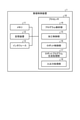
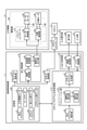
- the figure which shows the schematic structure of the numerical control apparatus which concerns on Embodiment 1. A block diagram showing a configuration of a numerical control device and a configuration of a machine tool according to the first embodiment.
- the figure for demonstrating the processing by each of the boundary point calculation part and the robot program generation part of the numerical control device which concerns on Embodiment 1. A flowchart showing a processing procedure by the interpolation point calculation unit of the numerical control device according to the first embodiment.
- FIG. 1 is a diagram showing a control system including a numerical control device according to the first embodiment.
- the control system includes a numerical control device 1 according to the first embodiment, a machine tool 2 for cutting a workpiece, a robot 3 for deburring additional machining, a robot controller 4 for driving the robot 3, and numerical values. It has an input operation unit 5 that receives an operation on the control device 1 and an operation on the robot 3. The robot 3 deburrs the machined workpiece.
- the numerical control device 1 controls the machine tool 2 and the robot 3 by executing an NC program.
- the machine tool 2 which is an NC machine tool is connected to the numerical control device 1.
- the robot 3 is connected to the numerical control device 1 via the robot controller 4.
- the numerical control device 1, the machine tool 2, and the robot controller 4 are connected to each other so as to be able to communicate with each other via a communication network.
- the communication network is, for example, a LAN (Local Area Network).
- the numerical control device 1 controls the robot 3 via the robot controller 4. In the following description, in the control of the robot 3 by the numerical control device 1, it may be omitted that the robot controller 4 is used.
- the input operation unit 5 has an input / output unit 6, an operation panel 7, a manual handle 8, and an emergency stop button 9.
- the operation panel 7 receives an operation from the user and sends a signal corresponding to the operation to the input / output unit 6.
- the emergency stop button 9 is pressed by the user, the signal for stopping the robot controller 4 is sent to the robot controller 4, and the signal for stopping the machine tool 2 is sent to the input / output unit 6.
- the input / output unit 6 sends the signal sent from the operation panel 7 and the signal sent from the emergency stop button 9 to the numerical control device 1.
- the emergency stop button 9 and the input / output unit 6 may be arranged on the operation panel 7.
- the robot controller 4 makes the robot 3 make an emergency stop.
- the numerical control device 1 receives a signal for stopping the machine tool 2 from the input / output unit 6, the machine tool 2 is stopped in an emergency.
- FIG. 2 is a diagram showing a schematic configuration of the numerical control device according to the first embodiment.
- the numerical control device 1 is a computer system such as a personal computer.
- a control program for supervising the control described in the first embodiment is installed in the computer system.
- FIG. 2 shows a functional configuration of the numerical control device 1 and a hardware configuration for realizing the functions of the numerical control device 1.
- the numerical control device 1 includes a processor 10 that is a processing unit that executes various processes, a memory 11 that is a built-in memory, a storage device 12 that stores information, and an interface 13 that is connected to an external device of the numerical control device 1. And have.
- the processor 10 is a CPU (Central Processing Unit).
- the processor 10 may be a processing device, an arithmetic unit, a microprocessor, a microcomputer, or a DSP (Digital Signal Processor).
- the memory 11 is a RAM (Random Access Memory), a ROM (Read Only Memory), a flash memory, an EPROM (Erasable Programmable Read Only Memory) or an EEPROM (registered trademark) (Electrically Erasable Programmable Read Only Memory).
- the storage device 12 is an HDD (Hard Disk Drive) or an SSD (Solid State Drive).
- the control program is stored in the storage device 12.
- the processor 10 reads the control program stored in the storage device 12 into the memory 11 and executes it.
- the interface 13 is connected to the machine tool 2, the robot controller 4, and the input operation unit 5.
- the numerical control device 1 includes a program analysis unit 14 that analyzes an NC program, a machining control unit 15 that controls a machine tool 2, and a robot control unit 16 that controls a robot 3.
- the machining control unit 15 controls the machine tool 2 by executing a machining program which is an NC program.
- the robot control unit 16 controls the robot 3 by executing a robot program which is an NC program.
- the numerical control device 1 includes a robot program generation processing unit 17 that executes processing for generating a robot program, and an input / output processing unit that is responsible for processing for input from the input operation unit 5 and output to the input operation unit 5. It has 18.
- Each function of the program analysis unit 14, the processing control unit 15, the robot control unit 16, the robot program generation processing unit 17, and the input / output processing unit 18 is realized by a combination of the processor 10 and software.
- Each of the functions may be realized by the combination of the processor 10 and the firmware, or may be realized by the combination of the processor 10, the software and the firmware.
- the software or firmware is described as a program and stored in the storage device 12. Details of each function will be described later.
- FIG. 3 is a block diagram showing a configuration of a numerical control device and a configuration of a machine tool according to the first embodiment.
- FIG. 3 also shows the robot 3, the robot controller 4, and the input operation unit 5.
- the machine tool 2 has a drive unit 40 that drives a machining tool and a work.
- the drive unit 40 drives the machining tool in a straight line while rotationally driving the work.
- the machining tool can be driven straight in three directions of the X-axis direction, the Y-axis direction, and the Z-axis direction.
- the X-axis, Y-axis, and Z-axis are three axes that are perpendicular to each other.
- the machine tool 2 is not limited to a machine tool 2 capable of driving a machining tool in a straight line in the above three directions.
- the direction in which the machining tool can be driven in a straight line can be appropriately set depending on the configuration of the machine tool 2.
- the drive unit 40 has a servomotor 44, a drive shaft that rotates in response to the drive force generated by the servomotor 44, and a mechanism that converts the rotary drive of the drive shaft into a straight drive.
- the drive shaft for driving the machining tool in a straight line may be referred to as a straight shaft.
- the linear axis and the mechanism are not shown.
- the drive unit 40 has a straight axis for driving the machining tool in the X-axis direction, a straight axis for driving the machining tool in the Y-axis direction, and a straight axis for driving the machining tool in the Z-axis direction.
- the drive unit 40 has a detector 48 that detects the rotation angle and speed of the servomotor 44.
- the drive controller 41 of the drive unit 40 receives a movement command from the numerical control device 1.
- the drive controller 41 has a servo control unit 42 that controls the servomotor 44 based on a movement command from the numerical control device 1.
- the servo control unit 42 performs feedback control of the servomotor 44 based on the detection result by the detector 48.
- the drive unit 40 includes a servo control unit 42, a servomotor 44 and a detector 48 for linear drive in the X-axis direction, and a servo control unit 42, a servomotor 44 and a detector 48 for linear drive in the Y-axis direction.
- the machine tool 2 may have two or more turrets for processing two or more workpieces at the same time. In this case, the drive unit 40 has the above combination for each tool post.
- the drive unit 40 has a rotary shaft that is a spindle for rotating the work, and a spindle motor 45 that applies a driving force to the rotary shaft.
- the machine tool 2 changes the posture of the work with respect to the machining tool by rotationally driving around the rotation axis. In FIG. 3, the rotation axis is not shown.
- the drive unit 40 has a detector 49 that detects the rotation angle and speed of the spindle motor 45.
- the drive unit 40 has one or more rotation axes.
- the machine tool 2 may change the posture of the work with respect to the machine tool by rotating the machine tool with respect to the work. Therefore, the rotation shaft of the drive unit 40 is not limited to the rotation shaft for rotating the work, and may be a rotation shaft for rotating the machining tool.
- the drive controller 41 has a spindle control unit 43 that controls the spindle motor 45 based on a movement command from the numerical control device 1.
- the spindle control unit 43 performs feedback control of the spindle motor 45 based on the detection result by the detector 49.
- the drive unit 40 has a combination of a spindle control unit 43, a spindle motor 45, and a detector 49 for each turret.
- the robot controller 4 receives a robot command from the numerical control device 1.
- the robot controller 4 calculates a command for driving each of the plurality of joints constituting the robot 3 based on the robot command.
- the robot controller 4 drives the robot 3 by transmitting the calculated command to the robot 3.
- the input operation unit 5 has a display unit 46 that displays a screen corresponding to image data input from the numerical control device 1, and an input unit 47 that accepts an operation on the numerical control device 1.
- Each function of the display unit 46 and the input unit 47 is realized by an input device having a touch panel.
- the buttons constituting the input unit 47 are displayed on the display unit 46.
- the operation panel 7, the manual handle 8, and the emergency stop button 9 shown in FIG. 1 may be included in the input unit 47.
- the input / output unit 6 may be provided in the input device.
- the numerical control device 1 has a storage unit 20.
- the function of the storage unit 20 is realized by using the storage device 12.
- the storage unit 20 stores the machining program 21 and the robot program 22.
- the machining program 21 is an NC program created by a CAM (Computer Aided Manufacturing) device.
- the robot program 22 is an NC program generated by the robot program generation processing unit 17.
- the storage unit 20 stores machine tool data 23, work data 24, machining tool data 25, and robot tool data 26.
- the machine tool data 23 is mainly structural data indicating the structure of the machine tool 2, and includes data indicating the specifications of the machine tool 2.
- the numerical control device 1 identifies the position of the machining tool by using the machine tool data 23.
- the work data 24 includes data indicating the size of the work and the installation position of the work.
- the machining tool data 25 is data about the shape of the machining tool used for cutting by the machine tool 2.
- the machining tool data 25 includes data such as the diameter of the machining tool and the length of the machining tool.
- the robot tool data 26 is data about the shape of the robot tool used for deburring by the robot 3.
- the robot tool data 26 includes data such as the radius of the robot tool and the length of the robot tool.
- the program analysis unit 14 reads the machining program 21 from the storage unit 20.
- the program analysis unit 14 analyzes the command position and the command speed based on the contents of the process described in the machining program 21.
- the program analysis unit 14 analyzes the command angle of the work based on the content of the process described in the machining program 21.
- the program analysis unit 14 outputs the analysis results of the command position, the command speed, and the command angle to the machining control unit 15.
- the machining control unit 15 has an interpolation processing unit 27, an acceleration / deceleration processing unit 28, and an axis command output unit 29. Based on the analysis result of the command position and the command speed in the program analysis unit 14, the interpolation processing unit 27 obtains the movement amount for each control cycle in each of the three directions for driving the machining tool in a straight line. The interpolation processing unit 27 generates an interpolation point representing the position of the machining tool for each control cycle by the interpolation processing. Further, the interpolation processing unit 27 obtains the rotation angle of the work for each control cycle based on the analysis result of the command angle in the program analysis unit 14. The interpolation processing unit 27 generates an interpolation point representing the rotation angle of the work for each control cycle by the interpolation processing. The interpolation processing unit 27 outputs the interpolation result which is the generated interpolation point.
- the acceleration / deceleration processing unit 28 executes acceleration / deceleration processing of the interpolation result.
- the axis command output unit 29 generates a movement command for the linear drive of the machining tool in each axial direction based on the interpolation result after the acceleration / deceleration process.
- the axis command output unit 29 generates a movement command for the rotational drive of the work based on the interpolation result after the acceleration / deceleration process.
- the movement command is a group of interpolation points for each control cycle.
- the axis command output unit 29 outputs the generated movement command to each of the servo control unit 42 and the spindle control unit 43.
- the program analysis unit 14 reads out the robot program 22 from the storage unit 20.
- the program analysis unit 14 analyzes the command position and the command speed of the robot tool based on the contents of the process described in the robot program 22.
- the program analysis unit 14 outputs the analysis result of the command position and the command speed to the robot control unit 16.
- the robot control unit 16 generates an interpolation point cloud for each unit time based on the analysis result.
- the robot control unit 16 converts the generated interpolation point cloud into a robot command which is a command in a format that can be interpreted by the robot controller 4.
- the robot control unit 16 outputs a robot command to the robot controller 4.
- the input / output processing unit 18 has an image processing unit 35 that generates image data, and an input control unit 36 that executes processing for input from the input operation unit 5.
- the image processing unit 35 outputs the generated image data to the display unit 46.
- the input unit 47 notifies the input control unit 36 of the content of the operation.
- the display unit 46 displays a start button for instructing the start of generation of the robot program.
- the input unit 47 notifies the input control unit 36 that the start of generation of the robot program has been instructed.
- the input control unit 36 activates the robot program generation processing unit 17 according to the notification.
- the robot program generation processing unit 17 has a machining program analysis unit 30, a simulation unit 31, and a robot program generation unit 32.
- the machining program analysis unit 30 reads the machining program 21 from the storage unit 20.
- the machining program analysis unit 30 analyzes the command position and command speed of the machining tool for each block of the machining program 21 by analyzing the machining program 21.
- the analysis is, for example, a character string analysis.
- the machining program analysis unit 30 analyzes the command angle of the work for each block of the machining program 21.
- the machining program analysis unit 30 outputs the analysis results of the command position, the command speed, and the command angle to the simulation unit 31.
- the simulation unit 31 has an interpolation point calculation unit 33 and a boundary point calculation unit 34.
- the interpolation point calculation unit 33 calculates the interpolation points for each unit time for the straight drive and the rotation drive based on the analysis result in the machining program analysis unit 30.
- the unit time represents the interpolation cycle in the interpolation point calculation unit 33.
- the interpolation point calculated by the interpolation point calculation unit 33 is the same as the interpolation point at the time of actual cutting.
- the interpolation point calculation unit 33 outputs the calculated interpolation point data to the boundary point calculation unit 34.
- the boundary point calculation unit 34 calculates a plurality of boundary points indicating the boundaries of the regions of the work to be removed by cutting based on the analysis results of the machining program 21. Specifically, the boundary point calculation unit 34 calculates a plurality of boundary points based on the plurality of interpolation points calculated based on the analysis result of the machining program 21 and the machining tool data 25.
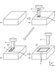
- FIG. 4 is a diagram for explaining the processing of the simulation unit included in the numerical control device according to the first embodiment.
- the interpolation point calculation unit 33 reads out the machine tool data 23, the work data 24, and the machining tool data 25 stored in the storage unit 20.
- the interpolation point calculation unit 33 calculates the machining tool position for each unit time based on the calculation result of the interpolation point for each unit time, the machine tool data 23, and the machining tool data 25.
- the machining tool data 25 includes data on the tool diameter R and the tool length L for the machining tool 51.
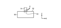
- FIG. 5 is a diagram for explaining the processing of the boundary point calculation unit included in the numerical control device according to the first embodiment.
- FIG. 5 shows how the tip 53 of the machining tool 51 advances below the upper surface 52 of the work 50 due to cutting.
- the boundary point P represents the boundary between the region AR removed by cutting and the region remaining without being removed in the upper surface 52 of the work 50.
- the boundary point calculation unit 34 carries out a simulation of moving the machining tool 51 every unit time according to the machining program 21, and calculates the coordinates representing the position of the boundary point P based on the machining tool position and the work data 24.
- the boundary point calculation unit 34 deletes the boundary point P'that is no longer the boundary of the region AR at any time due to the progress of cutting by the processing tool 51. In this way, the boundary point calculation unit 34 obtains a plurality of boundary points P when the cutting process for the region AR is completed.
- the boundary point calculation unit 34 adds time-series data indicating the cutting order to the coordinates of each boundary point P in the region AR.
- the boundary point calculation unit 34 refers to the movement path of the machining tool 51 instructed by the machining program 21, and determines the time from the start of cutting in the region AR until the machining tool 51 reaches each machining tool position. calculate.
- the boundary point calculation unit 34 generates time-series data for each boundary point P based on the calculation result of the time required.
- the time series data is data representing the calculated time.
- the time series data may be a numerical value representing the cutting order.
- the boundary point calculation unit 34 can obtain a numerical value representing the order based on the calculated time.
- the boundary point calculation unit 34 outputs the coordinates of each boundary point P and the time series data assigned to the coordinates to the robot program generation unit 32.
- the coordinates of the plurality of boundary points P for the area AR and the time-series data given to the coordinates are input to the robot program generation unit 32.
- the robot program generation unit 32 sets a route that follows each of the plurality of boundary points P in the order indicated by the time series data.
- the robot program generation unit 32 generates a robot program for moving a machining tool on the path.
- FIG. 6 is a diagram for explaining processing by each of the boundary point calculation unit and the robot program generation unit of the numerical control device according to the first embodiment.
- the four boundary points Pt0 shown in FIG. 6 are points on the boundary formed by cutting at the first machining tool position in the region AR. Time-series data representing the time t0 at the start of machining is added to the coordinates of each boundary point Pt0.
- the two boundary points Pt1 shown in FIG. 6 are points on the boundary formed by cutting at the position of the second machining tool in the region AR. Time-series data representing the time t1 from the start of machining to the arrival of the machining tool 51 at the machining tool position is added to the coordinates of each boundary point Pt1.
- the boundary points Pt2, Pt3, Pt4, Pt5, Pt6, and Pt7 are the same as those of the boundary point Pt0 and the boundary point Pt1.
- the robot program generation unit 32 reads out the robot tool data 26 stored in the storage unit 20.
- the robot tool data 26 includes data on the tool diameter and the tool length for the robot tool.
- the robot program generation unit 32 is a robot for moving the robot tool on the path following each boundary point Pt0-Pt7 in the same time series as the cutting process based on the coordinates of each boundary point Pt0-Pt7 and the time series data.
- the robot program generation unit 32 generates a robot program in which the shape of the robot tool is added, based on the read robot tool data 26.
- the robot program generation unit 32 determines each boundary in order from the boundary point farthest from the boundary point to which the next time-series data of the time-series data is assigned. Set the route to follow the points. For example, each of the four boundary points Pt0 is given time-series data representing the same time t0. The robot program generation unit 32 sets one of the four boundary points Pt0 as the starting point, which is the farthest from the boundary point Pt1 to which the time series data representing the time t1 is assigned. The robot program generation unit 32 sets a route from the boundary point Pt0 as the starting point to the boundary point Pt1.
- the robot program generation unit 32 sets the routes that sequentially follow each route Qt1, Qt2, Qt3, Qt4, Qt5 shown in FIG.
- the robot program generation unit 32 generates a robot command, which is a movement command for moving a robot tool along a set path.
- the robot program generation unit 32 generates a robot program 22 including the generated robot command.
- the storage unit 20 stores the robot program 22 generated by the robot program generation unit 32.
- FIG. 7 is a flowchart showing a processing procedure by the interpolation point calculation unit included in the numerical control device according to the first embodiment.
- the interpolation point calculation unit 33 acquires the analysis results of the command position and the command speed from the machining program analysis unit 30.
- the interpolation point calculation unit 33 calculates each interpolation point for the straight drive and the rotary drive.
- the interpolation point calculation unit 33 outputs the coordinates indicating each calculated interpolation point to the boundary point calculation unit 34.
- the interpolation point calculation unit 33 ends the process according to the procedure shown in FIG. 7.
- FIG. 8 is a flowchart showing a processing procedure by the boundary point calculation unit included in the numerical control device according to the first embodiment.
- the boundary point calculation unit 34 acquires the coordinates of each interpolation point from the interpolation point calculation unit 33.
- the boundary point calculation unit 34 reads the machine tool data 23 and the machining tool data 25 from the storage unit 20.
- step S13 the boundary point calculation unit 34 calculates the machining tool position for each unit time based on the coordinates of each interpolation point, the machine tool data 23, and the machining tool data 25.
- step S14 the boundary point calculation unit 34 reads the work data 24 from the storage unit 20.
- step S15 the boundary point calculation unit 34 calculates a region of the work 50 to be removed by cutting based on the calculated machining tool position and the work data 24.
- step S16 the boundary point calculation unit 34 determines whether or not the work 50 is cut.
- step S17 the boundary point calculation unit 34 calculates the coordinates of the boundary point with respect to the calculated machining tool position.
- the boundary point calculation unit 34 executes the determination in step S16 for each machining tool position for each unit time, and calculates the coordinates of the boundary point.
- step S18 the boundary point calculation unit 34 associates the time series data with the calculated coordinates of the boundary point.
- the boundary point calculation unit 34 ends the process according to the procedure shown in FIG.
- FIG. 9 is a flowchart showing a processing procedure by the robot program generation unit of the numerical control device according to the first embodiment.
- the robot program generation unit 32 acquires the coordinates of the boundary points and the time-series data associated with the coordinates for the plurality of boundary points in the region removed by cutting.
- the robot program generation unit 32 reads the robot tool data 26 from the storage unit 20.
- step S23 the robot program generation unit 32 sorts the coordinates of the boundary points read in step S21 in chronological order.
- step S24 the robot program generation unit 32 generates a robot command for moving the robot tool along the path passing through each boundary point according to the time series of each boundary point. In this route, the boundary points are connected by a straight line.
- step S25 the robot program generation unit 32 adds the robot command generated in step S24 to the robot program 22. As a result, the robot program generation unit 32 ends the process according to the procedure shown in FIG.
- FIG. 10 is a diagram showing an example of a machining program and a robot program stored in the numerical control device according to the first embodiment.
- a block having the sequence number “N1” is described at the beginning of the machining program 21.
- the machining program 21 describes positioning between the work 50 and the machine tool 2, a rotation command for the spindle, a cutting command which is a command for cutting, and the like.
- a G1 command that is, a command for linear interpolation that moves two points in a straight line is described for cutting into a work 50 having an arbitrary shape.
- a block with the sequence number "N1001" is described at the beginning of the robot program 22.
- the robot program 22 describes positioning between the work 50 and the robot 3, additional machining commands that are commands for deburring.
- the numerical control device 1 generates a robot program 22 for deburring the work 50 machined by executing the machining program 21 described above.
- FIG. 11 is a flowchart showing an operation procedure of the numerical control device when the numerical control device according to the first embodiment automatically starts a machining program or a robot program.
- the program analysis unit 14 determines whether or not the program currently being analyzed is the machining program 21.
- the program analysis unit 14 determines whether the analysis target is the machining program 21 or the robot program 22 based on the contents of the block in the analysis target.
- the program analysis unit 14 analyzes the end point position or the command speed of each command.
- the program analysis unit 14 analyzes the machining program 21 in step S32.
- the program analysis unit 14 outputs the analysis result to the interpolation processing unit 27.
- the interpolation processing unit 27 executes an interpolation process for generating an interpolation point.
- the acceleration / deceleration processing unit 28 executes acceleration / deceleration processing.
- the axis command output unit 29 generates a movement command for the linear drive of the machining tool and a movement command for the rotational drive of the work 50 based on the interpolation result after the acceleration / deceleration process.
- the axis command output unit 29 outputs the generated movement command to the drive controller 41.
- step S31, No when the analysis target is not the machining program 21 (steps S31, No), that is, when the machining target is the robot program 22, the program analysis unit 14 analyzes the robot program 22 in step S33.
- the program analysis unit 14 outputs the analysis result to the robot control unit 16.
- the robot control unit 16 generates a robot command in a format that can be interpreted by the robot controller 4 based on the analysis result.
- step S37 the robot control unit 16 outputs the generated robot command to the robot controller 4.
- step S36 or step S37 the numerical control device 1 ends the operation according to the procedure shown in FIG.
- FIG. 12 is a diagram for explaining an example of deburring by executing a robot program generated in the numerical control device according to the first embodiment.
- the numerical control device 1 positions the machine tool so that the machine tool moves along a path slightly different from the path following the command point generated based on the CAD data for the purpose of shortening the time required for cutting. May be controlled. Therefore, the machining tool may move a path slightly different from the path passing through each command point generated based on the CAD data.
- the machining tool moves a path TR that draws a curve between the command points CP1 and CP4 with respect to the path CR passing through each command point CP1, CP2, CP3, CP4.
- the robot tool does not reach the command points CP2 and CP3, and deburring is not performed in the vicinity of the command points CP2 and CP3. become.
- the numerical control device 1 calculates a plurality of boundary points indicating the boundaries of the regions removed by cutting, and is a robot program for moving the robot tool on a path following the plurality of boundary points. 22 is generated.
- the numerical control device 1 can generate a robot program 22 capable of moving a robot tool along the shape of a machine 50 that has been machined.
- the numerical control device 1 can perform highly accurate deburring according to the shape of the machine 50 that has been machined.
- the numerical control device 1 can perform high-precision deburring according to the shape of the machined work 50 without using a camera or the like for measuring the shape of the work 50 after the machined work. ..
- the numerical control device 1 has the effect of enabling highly accurate deburring of the machine 50 that has been machined.
- Embodiment 2 the operation of the numerical control device 1 for simultaneously performing the cutting work by the machine tool 2 and the additional work of deburring by the robot 3 will be described.
- the numerical control device 1 according to the second embodiment has the same configuration as the numerical control device 1 according to the first embodiment.
- the same components as those in the first embodiment are designated by the same reference numerals, and the configurations different from those in the first embodiment will be mainly described.
- control system performs the cutting and the additional machining in parallel by starting the additional machining by the robot 3 after the cutting to any part of the work 50 is completed.
- the control system can shorten the tact time by performing cutting and additional machining in parallel. This makes it possible for the control system to shorten the machining time.
- FIG. 13 is a diagram showing an example of a machining program and a robot program stored in the numerical control device according to the second embodiment.
- the robot program generation unit 32 adds an additional work standby command to the generated robot program 22.
- the numerical control device 1 can perform cutting and additional machining in parallel, and can obtain the effect of shortening the machining time.
- the machining program 21 includes a command for designating a machining range by the robot 3.
- each of the labels "LABEL_A”, “LABEL_B”, and “LABEL_C” is a command for designating an area where additional machining is performed by the robot 3.
- "LABEL_A” is a label for designating the area A.
- "LABEL_B” is a label for designating the area B.
- "LABEL_C” is a label for designating the area C.
- the user of the control system can add an arbitrary command for designating a machining range to the machining program 21 created by the CAM device. A command for designating the start of the machining range and a command for designating the end of the machining range are added to the machining program 21 for each region.
- the configuration of the robot program generation processing unit 17 in the second embodiment is the same as the configuration of the robot program generation processing unit 17 in the first embodiment.
- the robot program generation unit 32 attaches the above label to the analysis result of the command position and the command speed by the machining program analysis unit 30. Further, the robot program generation unit 32 assigns the above label to each boundary point calculated by the simulation unit 31.
- the numerical control device 1 adds to the robot program 22 an additional machining standby command corresponding to a command for designating a machining range included in the machining program 21.
- the additional work standby command is a standby command for making the additional work stand by.
- the robot program generation unit 32 adds an additional machining standby command to the robot program 22 by executing a command for designating a machining range.
- an additional machining standby command for the region A is added before the additional machining command for deburring processing in the region A.
- An additional machining standby command for the region B is added before the additional machining command for the deburring process of the region B.
- An additional machining standby command for the region C is added before the additional machining command for the deburring process of the region C.
- the image processing unit 35 shown in FIG. 3 generates image data for displaying the calculation result of each boundary point by the simulation unit 31.
- the display unit 46 displays the calculation result of each boundary point according to the image data.
- FIG. 14 is a diagram showing an example of a screen displaying the calculation result of the boundary point by the numerical control device according to the second embodiment.
- FIG. 14 shows an example in which the machining program 21 includes two labels “LABEL_A” and “LABEL_B”.
- the “cutting range of label A” represents the region A designated by “LABEL_A”.
- the "coordinate data of the label A” represents the coordinates of each boundary point of the area A.
- the "cutting range of label B" represents the area B designated by "LABEL_B”.
- the "coordinate data of the label B” represents the coordinates of each boundary point of the area B.
- the display unit 46 displays the calculation result of each boundary point separately for each label.
- FIG. 15 is a diagram for explaining the operation of the machine tool and the robot when the machining program and the robot program are executed in the numerical control device according to the second embodiment.
- the numerical control device 1 has a plurality of systems. Each of the plurality of systems is a processing system for executing an NC program.
- the numerical control device 1 executes the machining program 21 and the robot program 22 in different systems.
- the system that executes the machining program 21 may be referred to as a first system
- the system that executes the robot program 22 may be referred to as a second system.
- the area AR1 represents the area A and the area AR2 represents the area B.
- the robot 3 waits for additional machining for deburring in the region AR1 in accordance with the additional machining standby command included in the robot program 22.
- the robot 3 waits for additional machining until a command for designating the end of the machining range is executed for the region AR1 in the machining program 21.
- the robot 3 starts deburring the area AR1 by the robot tool 60.
- the machine tool 2 performs the cutting process of the area AR2.
- the numerical control device 1 makes the area AR1 deburring wait until the cutting process of the area AR1 is completed. Further, after the cutting of the region AR1 is completed, the numerical control device 1 performs deburring of the region AR1 and cutting of the region AR2 in parallel.
- FIG. 16 is a flowchart showing a processing procedure by the processing program analysis unit included in the numerical control device according to the second embodiment.
- the machining program analysis unit 30 determines whether or not the read block in the machining program 21 is a command for designating the start of the machining range by the robot 3.
- the machining program analysis unit 30 sets the program generation mode in step S42 to enable labeling. Switch to. In the mode in which labeling is enabled, the machining program analysis unit 30 assigns the above label to the analysis result of the command position and the command speed.
- the machining program analysis unit 30 determines that the read block in the machining program 21 is in step S43. , It is determined whether or not it is a command for designating the end of the machining range by the robot 3.
- the machining program analysis unit 30 sets the program generation mode to the invalid labeling mode in step S44. Switch to. In the mode in which labeling is invalidated, the machining program analysis unit 30 does not add the above labels to the analysis results of the command position and the command speed.
- step S45 the machining program analysis unit 30 displays in step S45 that the current program generation mode is labeled. Determine if the mode is valid.
- the machining program analysis unit 30 outputs the labeled analysis result to the simulation unit 31 in step S46.
- the current program generation mode is a mode in which labeling is invalidated (steps S45 and No)
- step S47 the machining program analysis unit 30 outputs the analysis result without the label to the simulation unit 31.
- FIG. 17 is a flowchart showing a processing procedure by the interpolation point calculation unit included in the numerical control device according to the second embodiment.
- the interpolation point calculation unit 33 acquires the analysis results of the command position and the command speed from the machining program analysis unit 30.
- the interpolation point calculation unit 33 calculates each interpolation point for the straight drive and the rotary drive.
- step S53 the interpolation point calculation unit 33 determines whether or not the analysis result acquired in step S51 is a labeled analysis result.
- the interpolation point calculation unit 33 associates the label with the coordinates of the calculated interpolation point.
- the interpolation point calculation unit 33 outputs the coordinates of the interpolation point to which the label is associated to the boundary point calculation unit 34.
- step S53 when the acquired analysis result is not a labeled analysis result (step S53, No), the interpolation point calculation unit 33 skips step S54.
- the interpolation point calculation unit 33 outputs the coordinates of the interpolation point to which the label is not associated to the boundary point calculation unit 34.
- step S54 By executing step S54 or skipping step S54, the interpolation point calculation unit 33 ends the process according to the procedure shown in FIG.
- FIG. 18 is a flowchart showing a processing procedure by the boundary point calculation unit included in the numerical control device according to the second embodiment.
- the boundary point calculation unit 34 acquires the coordinates of each interpolation point from the interpolation point calculation unit 33.
- the boundary point calculation unit 34 reads the machine tool data 23 and the machining tool data 25 from the storage unit 20.
- step S63 the boundary point calculation unit 34 calculates the machining tool position for each unit time based on the coordinates of each interpolation point, the machine tool data 23, and the machining tool data 25.
- step S64 the boundary point calculation unit 34 reads the work data 24 from the storage unit 20.
- step S65 the boundary point calculation unit 34 calculates a region of the work 50 to be removed by cutting based on the calculated machining tool position and the work data 24.
- step S66 the boundary point calculation unit 34 determines whether or not the work 50 is cut.
- step S67 the boundary point calculation unit 34 calculates the coordinates of the boundary point with respect to the calculated machining tool position.
- the boundary point calculation unit 34 executes the determination in step S66 for each machining tool position for each unit time, and calculates the coordinates of the boundary point.
- step S68 the boundary point calculation unit 34 associates the time series data with the calculated coordinates of the boundary point.
- step S69 the boundary point calculation unit 34 determines whether or not the calculated boundary point is the boundary point for the labeled interpolation point.
- step S70 the boundary point calculation unit 34 associates the label with the coordinates of the calculated boundary point. ..
- the boundary point calculation unit 34 outputs the coordinates of the boundary point to which the label and the time series data are associated to the robot program generation unit 32.
- step S69, No when the calculated boundary point is not the boundary point for the labeled interpolation point (step S69, No), the boundary point calculation unit 34 skips step S70.
- the boundary point calculation unit 34 outputs the coordinates of the boundary point to which only the time series data is associated with the time series data and the label to the robot program generation unit 32.
- step S70 or skipping step S70 the boundary point calculation unit 34 ends the process according to the procedure shown in FIG.
- the boundary point calculation unit 34 ends the process according to the procedure shown in FIG.
- FIG. 19 is a flowchart showing a processing procedure by the robot program generation unit included in the numerical control device according to the second embodiment.
- the robot program generation unit 32 acquires the coordinates of the boundary points and the time-series data associated with the coordinates for the plurality of boundary points in the region removed by cutting.
- step S82 the robot program generation unit 32 determines whether or not the boundary point acquired in step S81 is a labeled boundary point. If the boundary point is not a labeled boundary point (steps S82, No), the robot program generation unit 32 advances the procedure to step S86.
- step S83 the robot program generation unit 32 determines whether or not the previous boundary point is an unlabeled boundary point.
- the previous boundary point is the boundary point acquired by the robot program generation unit 32 immediately before the boundary point acquired in step S81.
- the robot program generation unit 32 advances the procedure to step S85.
- step S84 the robot program generation unit 32 uses the boundary point label acquired in step S81 as the previous boundary point. Determine if it is different from the label of.
- the robot program generation unit 32 advances the procedure to step S86.
- the robot program generation unit 32 advances the procedure to step S85.
- step S85 the robot program generation unit 32 adds an additional work standby command corresponding to the label of the boundary point acquired in step S81 to the robot program 22.
- the robot program generation unit 32 advances the procedure to step S86 by executing step S85.
- step S86 the robot program generation unit 32 reads the robot tool data 26 from the storage unit 20.
- step S87 the robot program generation unit 32 sorts the coordinates of the boundary points read in step S81 in chronological order.
- step S88 the robot program generation unit 32 generates a robot command for moving the robot tool along the path passing through each boundary point according to the time series of each boundary point. In this route, the boundary points are connected by a straight line.
- step S89 the robot program generation unit 32 adds the robot command generated in step S88 to the robot program 22. As a result, the robot program generation unit 32 ends the process according to the procedure shown in FIG.
- the numerical control device 1 executes the machining program 21 in the first system and the robot program 22 in the second system. As a result, the control system simultaneously performs cutting by the machine tool 2 and additional machining by the robot 3.
- FIG. 20 is a flowchart showing an operation procedure of the numerical control device when the numerical control device according to the second embodiment automatically starts a machining program or a robot program.
- the program analysis unit 14 determines whether or not the program currently being analyzed is the machining program 21.
- step S91 the program analysis unit 14 analyzes the machining program 21 in step S92.
- step S94 the program analysis unit 14 determines whether or not the block to be executed is a block of a command for designating the end of the machining range by the robot 3.
- step S95 the program analysis unit 14 notes the label corresponding to the finished machining range.
- the program analysis unit 14 leaves a label indicating that the cutting process in the processing range has been completed.
- the robot 3 performs the additional machining, it determines whether or not the cutting process, which is the premise of the additional machining, has been completed in the machining range that is the target of the additional machining, based on the label.
- the program analysis unit 14 skips step S95.
- the program analysis unit 14 outputs the analysis result to the interpolation processing unit 27.
- step S95 or skipping step S95 the numerical control device 1 advances the procedure to step S96.
- step S96 the interpolation processing unit 27 executes an interpolation process for generating an interpolation point.
- step S97 the acceleration / deceleration processing unit 28 executes acceleration / deceleration processing.
- the axis command output unit 29 generates a movement command for the linear drive of the machining tool and a movement command for the rotational drive of the work 50 based on the interpolation result after the acceleration / deceleration process.
- the axis command output unit 29 outputs the generated movement command to the drive controller 41.
- step S91 when the analysis target is not the machining program 21 (steps S91, No), that is, when the machining target is the robot program 22, the program analysis unit 14 analyzes the robot program 22 in step S93.
- step S99 the program analysis unit 14 determines whether or not the block to be executed is a block of an additional work standby command.
- step S99, No the numerical control device 1 skips step S100 and advances the procedure to step S101.
- step S100 when the block to be executed is a block of an additional machining standby command (step S99, Yes), in step S100, has the program analysis unit 14 already executed the block of the command for designating the end of the machining range? Judge whether or not.
- the numerical control device 1 advances the procedure to step S101.
- the block of the command for designating the end of the machining range has not been executed (step S100, No)
- the numerical control device 1 performs step S100 until the command for designating the end of the machining range is executed. Repeat the judgment in.
- the program analysis unit 14 outputs the analysis result to the robot control unit 16.
- the robot control unit 16 generates a robot command in a format that can be interpreted by the robot controller 4 based on the analysis result.
- step S101 the robot control unit 16 outputs the generated robot command to the robot controller 4.
- step S98 or step S101 the numerical control device 1 ends the operation according to the procedure shown in FIG.
- the program analysis unit 14 determines in steps S99 and S100 whether or not the cutting process up to the processing range indicated by the label left in step S95 is completed.
- the numerical control device 1 starts additional machining up to the machining range when the cutting machining up to the machining range is completed.
- the numerical control device 1 waits for the robot 3 to deburr the area until the cutting of the area to be cut is completed. Further, the numerical control device 1 can perform deburring of the region by the robot 3 and cutting by the machine tool 2 in the region to be cut next to the region in parallel. Since the control system can start deburring from the region where cutting is completed before the cutting of the entire work 50 is completed, the processing time can be shortened.
- each of the above embodiments shows an example of the contents of the present disclosure.
- the configurations of each embodiment can be combined with other known techniques.
- the configurations of the respective embodiments may be appropriately combined. It is possible to omit or change a part of the configuration of each embodiment without departing from the gist of the present disclosure.
- 1 numerical control device 2 machine machine, 3 robot, 4 robot controller, 5 input operation unit, 6 input / output unit, 7 operation panel, 8 manual handle, 9 emergency stop button, 10 processor, 11 memory, 12 storage device, 13 Interface, 14 program analysis unit, 15 processing control unit, 16 robot control unit, 17 robot program generation processing unit, 18 input / output processing unit, 20 storage unit, 21 processing program, 22 robot program, 23 machine machine data, 24 work data.
- machining program analysis section 25 machining tool data, 26 robot tool data, 27 interpolation processing section, 28 acceleration / deceleration processing section, 29 axis command output section, 30 machining program analysis section, 31 simulation section, 32 robot program generation section, 33 interpolation point calculation section, 34 boundary point calculation unit, 35 image processing unit, 36 input control unit, 40 drive unit, 41 drive controller, 42 servo control unit, 43 spindle control unit, 44 servo motor, 45 spindle motor, 46 display unit, 47 input unit, 48, 49 detector, 50 workpiece, 51 machining tool, 52 top surface, 53 tip, 60 robot tool.
Landscapes
- Engineering & Computer Science (AREA)
- Robotics (AREA)
- Mechanical Engineering (AREA)
- Manufacturing & Machinery (AREA)
- Physics & Mathematics (AREA)
- General Physics & Mathematics (AREA)
- Automation & Control Theory (AREA)
- General Engineering & Computer Science (AREA)
- Quality & Reliability (AREA)
- Human Computer Interaction (AREA)
- Numerical Control (AREA)
- Milling, Broaching, Filing, Reaming, And Others (AREA)
Abstract
数値制御装置(1)は、ワークの切削加工を行う工作機械(2)と、ワークのバリ取りのための工具が取り付けられたロボット(3)とを制御する。数値制御装置(1)は、ワークのうち切削加工によって除去される領域の境界を示す複数の境界点を、切削加工の制御のために実行される加工プログラム(21)の解析結果を基に算出する境界点算出部(34)と、複数の境界点を辿る経路上において工具を移動させるためのロボットプログラム(22)を生成するロボットプログラム生成部(32)とを備える。
Description
本開示は、ワークを加工する工作機械とワークのバリ取りを行うロボットとを制御する数値制御装置および数値制御方法に関する。
工作機械による切削加工が施されたワークについて、ロボットに取り付けられた工具によるバリ取りが実施されることがある。ロボットの駆動によるバリ取りでは、当該工具を移動させるためのロボットの位置制御が必要となる。なお、以下の説明では、工作機械に取り付けられる工具であって切削加工のための工具を加工工具、ロボットに取り付けられる工具であってバリ取りのための工具をロボット工具と称することがある。
特許文献1には、ワークの設計データであるCAD(Computer Aided Design)データからワークの理想形状データを取得し、理想形状データによって示される理想形状に沿ってロボット工具を移動させる方法が開示されている。
加工プログラムであるNC(Numerical Control)プログラムの実行によって工作機械を制御する数値制御装置は、切削加工の時間短縮などのために、CADデータを基に生成された指令点を辿る経路とは若干異なる経路に沿って加工工具が移動するように工作機械の位置制御を行う場合がある。上記特許文献1に開示される従来の技術によると、工作機械による切削加工後のワークの形状が考慮されずにロボットの位置制御が行われることから、切削加工が施されたワークに対する高精度なバリ取りを行うことが困難であるという問題があった。
本開示は、上記に鑑みてなされたものであって、切削加工が施されたワークに対する高精度なバリ取りを可能とする数値制御装置を得ることを目的とする。
上述した課題を解決し、目的を達成するために、本開示にかかる数値制御装置は、ワークの切削加工を行う工作機械と、ワークのバリ取りのための工具が取り付けられたロボットとを制御する。本開示にかかる数値制御装置は、ワークのうち切削加工によって除去される領域の境界を示す複数の境界点を、切削加工の制御のために実行される加工プログラムの解析結果を基に算出する境界点算出部と、複数の境界点を辿る経路上において工具を移動させるためのロボットプログラムを生成するロボットプログラム生成部とを備える。
本開示にかかる数値制御装置は、切削加工が施されたワークに対する高精度なバリ取りが可能となるという効果を奏する。
以下に、実施の形態にかかる数値制御装置および数値制御方法を図面に基づいて詳細に説明する。
実施の形態1.
図1は、実施の形態1にかかる数値制御装置を含む制御システムを示す図である。制御システムは、実施の形態1にかかる数値制御装置1と、ワークの切削加工を行う工作機械2と、追加工であるバリ取りを行うロボット3と、ロボット3を駆動するロボットコントローラ4と、数値制御装置1への操作とロボット3への操作とを受け付ける入力操作部5とを有する。ロボット3は、切削加工が施されたワークのバリ取りを行う。数値制御装置1は、NCプログラムの実行によって工作機械2とロボット3とを制御する。
図1は、実施の形態1にかかる数値制御装置を含む制御システムを示す図である。制御システムは、実施の形態1にかかる数値制御装置1と、ワークの切削加工を行う工作機械2と、追加工であるバリ取りを行うロボット3と、ロボット3を駆動するロボットコントローラ4と、数値制御装置1への操作とロボット3への操作とを受け付ける入力操作部5とを有する。ロボット3は、切削加工が施されたワークのバリ取りを行う。数値制御装置1は、NCプログラムの実行によって工作機械2とロボット3とを制御する。
NC工作機械である工作機械2は、数値制御装置1に接続されている。ロボット3は、ロボットコントローラ4を介して数値制御装置1に接続されている。数値制御装置1と、工作機械2およびロボットコントローラ4の各々とは、通信ネットワークを介して互いに通信可能に接続されている。通信ネットワークは、例えばLAN(Local Area Network)である。数値制御装置1は、ロボットコントローラ4を介してロボット3を制御する。以下の説明では、数値制御装置1によるロボット3の制御において、ロボットコントローラ4が介されていることを省略する場合がある。
入力操作部5は、入出力ユニット6、操作盤7、手動ハンドル8および非常停止ボタン9を有する。操作盤7は、ユーザからの操作を受け付けて、操作に対応する信号を入出力ユニット6に送る。非常停止ボタン9は、ユーザによって押下されると、ロボットコントローラ4を停止させるための信号をロボットコントローラ4に送るとともに、工作機械2を停止させるための信号を入出力ユニット6に送る。入出力ユニット6は、操作盤7から送られてくる信号および非常停止ボタン9から送られてくる信号を、数値制御装置1に送る。非常停止ボタン9および入出力ユニット6は、操作盤7に配置されてもよい。ロボットコントローラ4は、非常停止ボタン9からの信号を受けると、ロボット3を非常停止させる。数値制御装置1は、工作機械2を停止させるための信号を入出力ユニット6から受けると、工作機械2を非常停止させる。
次に、数値制御装置1の構成について説明する。図2は、実施の形態1にかかる数値制御装置の概略構成を示す図である。数値制御装置1は、パーソナルコンピュータなどのコンピュータシステムである。コンピュータシステムには、実施の形態1にて説明する制御を統括するための制御プログラムがインストールされる。図2には、数値制御装置1が有する機能構成と、数値制御装置1の機能を実現するためのハードウェア構成とを示している。
数値制御装置1は、各種処理を実行する処理部であるプロセッサ10と、内蔵メモリであるメモリ11と、情報を記憶する記憶装置12と、数値制御装置1の外部の装置に接続されるインタフェース13とを有する。
プロセッサ10は、CPU(Central Processing Unit)である。プロセッサ10は、処理装置、演算装置、マイクロプロセッサ、マイクロコンピュータ、又はDSP(Digital Signal Processor)であっても良い。メモリ11は、RAM(Random Access Memory)、ROM(Read Only Memory)、フラッシュメモリ、EPROM(Erasable Programmable Read Only Memory)またはEEPROM(登録商標)(Electrically Erasable Programmable Read Only Memory)である。記憶装置12は、HDD(Hard Disk Drive)またはSSD(Solid State Drive)である。制御プログラムは、記憶装置12に格納される。プロセッサ10は、記憶装置12に格納されている制御プログラムをメモリ11に読み出して実行する。インタフェース13は、工作機械2、ロボットコントローラ4および入力操作部5に接続される。
数値制御装置1は、NCプログラムを解析するプログラム解析部14と、工作機械2を制御する加工制御部15と、ロボット3を制御するロボット制御部16とを備える。加工制御部15は、NCプログラムである加工プログラムの実行によって工作機械2を制御する。ロボット制御部16は、NCプログラムであるロボットプログラムの実行によってロボット3を制御する。数値制御装置1は、ロボットプログラムを生成するための処理を実行するロボットプログラム生成処理部17と、入力操作部5からの入力と入力操作部5への出力のための処理を担う入出力処理部18とを有する。
プログラム解析部14、加工制御部15、ロボット制御部16、ロボットプログラム生成処理部17および入出力処理部18の各機能は、プロセッサ10とソフトウェアの組み合わせによって実現される。当該各機能は、プロセッサ10およびファームウェアの組み合わせによって実現されても良く、プロセッサ10、ソフトウェアおよびファームウェアの組み合わせによって実現されても良い。ソフトウェアまたはファームウェアは、プログラムとして記述され、記憶装置12に格納される。各機能の詳細については後述する。
図3は、実施の形態1にかかる数値制御装置の構成と工作機械の構成とを示すブロック図である。図3には、ロボット3、ロボットコントローラ4および入力操作部5も示している。
工作機械2は、加工工具とワークとを駆動する駆動部40を有する。駆動部40は、ワークを回転駆動しながら加工工具を直進駆動する。加工工具は、X軸方向、Y軸方向およびZ軸方向の3つの方向における直進駆動が可能とされている。X軸、Y軸およびZ軸は、互いに垂直な3つの軸とする。なお、工作機械2は、上記3つの方向において加工工具の直進駆動が可能であるものに限定されない。加工工具の直進駆動が可能な方向は、工作機械2の構成によって適宜設定可能である。
駆動部40は、サーボモータ44と、サーボモータ44が発生させた駆動力を受けて回転する駆動軸と、駆動軸の回転駆動を直進駆動へ変換する機構とを有する。以下の説明では、加工工具を直進駆動させるための当該駆動軸を、直進軸と称することがある。図3では、直進軸と当該機構との図示を省略する。
駆動部40は、X軸方向において加工工具を直進駆動するための直進軸と、Y軸方向において加工工具を直進駆動するための直進軸と、Z軸方向において加工工具を直進駆動するための直進軸とを有する。駆動部40は、サーボモータ44の回転角度および速度を検出する検出器48を有する。駆動部40のドライブコントローラ41は、数値制御装置1からの移動指令を受信する。ドライブコントローラ41は、数値制御装置1からの移動指令に基づいてサーボモータ44を制御するサーボ制御部42を有する。サーボ制御部42は、検出器48による検出結果に基づいてサーボモータ44のフィードバック制御を行う。
駆動部40は、X軸方向の直進駆動のためのサーボ制御部42、サーボモータ44および検出器48と、Y軸方向の直進駆動のためのサーボ制御部42、サーボモータ44および検出器48と、Z軸方向の直進駆動のためのサーボ制御部42、サーボモータ44および検出器48との組み合わせを有する。工作機械2は、2つ以上のワークを同時に加工するための2つ以上の刃物台を有しても良い。この場合、駆動部40は、刃物台ごとについての上記組み合わせを有する。
駆動部40は、ワークを回転させる主軸である回転軸と、回転軸へ駆動力を与える主軸モータ45を有する。工作機械2は、回転軸を中心とする回転駆動によって、加工工具に対するワークの姿勢を変化させる。図3では、回転軸の図示を省略する。駆動部40は、主軸モータ45の回転角度および速度を検出する検出器49を有する。駆動部40は、1または複数の回転軸を有する。工作機械2は、ワークに対して加工工具を回転させることによって、加工工具に対するワークの姿勢を変化させても良い。このため、駆動部40が有する回転軸は、ワークを回転させる回転軸に限られず、加工工具を回転させる回転軸であっても良い。
ドライブコントローラ41は、数値制御装置1からの移動指令に基づいて主軸モータ45を制御する主軸制御部43を有する。主軸制御部43は、検出器49による検出結果に基づいて主軸モータ45のフィードバック制御を行う。工作機械2が2つ以上の刃物台を有する場合、駆動部40は、刃物台ごとについての、主軸制御部43、主軸モータ45および検出器49の組み合わせを有する。
ロボットコントローラ4は、数値制御装置1からのロボット指令を受信する。ロボットコントローラ4は、ロボット指令を基に、ロボット3を構成する複数の関節の各々を駆動するための指令を算出する。ロボットコントローラ4は、算出された指令をロボット3へ送信することにより、ロボット3を駆動する。
入力操作部5は、数値制御装置1から入力される画像データに応じた画面を表示する表示部46と、数値制御装置1への操作を受け付ける入力部47とを有する。表示部46と入力部47との各機能は、タッチパネルを有する入力装置によって実現される。入力部47を構成するボタンは、表示部46に表示される。なお、図1に示す操作盤7、手動ハンドル8および非常停止ボタン9は、入力部47に含まれるものであっても良い。入出力ユニット6は、入力装置に備えられるものであっても良い。
数値制御装置1は、記憶部20を有する。記憶部20の機能は、記憶装置12を用いて実現される。記憶部20は、加工プログラム21と、ロボットプログラム22とを記憶する。加工プログラム21は、CAM(Computer Aided Manufacturing)装置によって作成されたNCプログラムである。ロボットプログラム22は、ロボットプログラム生成処理部17によって生成されたNCプログラムである。記憶部20は、工作機械データ23と、ワークデータ24と、加工工具データ25と、ロボット工具データ26とを記憶する。
工作機械データ23は、主に、工作機械2の構造を示す構造データであって、工作機械2の諸元を示すデータを含む。数値制御装置1は、工作機械データ23を用いることによって、加工工具の位置の識別などを行う。ワークデータ24は、ワークのサイズおよびワークの設置位置を示すデータを含む。加工工具データ25は、工作機械2による切削加工に使用される加工工具の形状についてのデータである。加工工具データ25は、加工工具の径および加工工具の長さといったデータを含む。ロボット工具データ26は、ロボット3によるバリ取りに使用されるロボット工具の形状についてのデータである。ロボット工具データ26は、ロボット工具の半径およびロボット工具の長さといったデータを含む。
プログラム解析部14は、記憶部20から加工プログラム21を読み出す。プログラム解析部14は、加工プログラム21に記述されている処理の内容を基に、指令位置と指令速度とを解析する。プログラム解析部14は、加工プログラム21に記述されている処理の内容を基に、ワークの指令角度を解析する。プログラム解析部14は、指令位置、指令速度および指令角度の解析結果を加工制御部15へ出力する。
加工制御部15は、補間処理部27と、加減速処理部28と、軸指令出力部29とを有する。補間処理部27は、プログラム解析部14における指令位置と指令速度との解析結果を基に、加工工具を直進駆動する3つの方向の各々について、制御周期ごとの移動量を求める。補間処理部27は、補間処理によって、制御周期ごとの加工工具の位置を表す補間点を生成する。また、補間処理部27は、プログラム解析部14における指令角度の解析結果を基に、制御周期ごとのワークの回転角度を求める。補間処理部27は、補間処理によって、制御周期ごとのワークの回転角度を表す補間点を生成する。補間処理部27は、生成された補間点である補間結果を出力する。
加減速処理部28は、補間結果の加減速処理を実行する。軸指令出力部29は、加減速処理後の補間結果を基に、各軸方向における加工工具の直進駆動についての移動指令を生成する。軸指令出力部29は、加減速処理後の補間結果を基に、ワークの回転駆動についての移動指令を生成する。移動指令は、制御周期ごとの補間点群である。軸指令出力部29は、生成された移動指令をサーボ制御部42と主軸制御部43との各々へ出力する。
プログラム解析部14は、記憶部20からロボットプログラム22を読み出す。プログラム解析部14は、ロボットプログラム22に記述されている処理の内容を基に、ロボット工具の指令位置と指令速度とを解析する。プログラム解析部14は、指令位置と指令速度との解析結果をロボット制御部16へ出力する。ロボット制御部16は、解析結果を基に、単位時間ごとの補間点群を生成する。ロボット制御部16は、生成された補間点群をロボットコントローラ4が解釈可能な形式の指令であるロボット指令へ変換する。ロボット制御部16は、ロボット指令をロボットコントローラ4へ出力する。
入出力処理部18は、画像データを生成する画像処理部35と、入力操作部5からの入力に対する処理を実行する入力制御部36とを有する。画像処理部35は、生成された画像データを表示部46へ出力する。表示部46に表示されたボタンが押下された場合に、入力部47は、入力制御部36へ操作の内容を通知する。
表示部46には、ロボットプログラムの生成開始を指示するための開始ボタンが表示される。当該開始ボタンが押下されることによって、入力部47は、ロボットプログラムの生成開始が指示されたことを入力制御部36へ通知する。入力制御部36は、当該通知に従って、ロボットプログラム生成処理部17を起動させる。
ロボットプログラム生成処理部17は、加工プログラム解析部30と、シミュレーション部31と、ロボットプログラム生成部32とを有する。ロボットプログラム生成処理部17の起動によって、加工プログラム解析部30は、記憶部20から加工プログラム21を読み出す。加工プログラム解析部30は、加工プログラム21の解析により、加工プログラム21のブロックごとにおける加工工具の指令位置および指令速度を解析する。解析は、例えば文字列解析である。また、加工プログラム解析部30は、加工プログラム21のブロックごとにおけるワークの指令角度を解析する。加工プログラム解析部30は、指令位置、指令速度および指令角度の解析結果をシミュレーション部31へ出力する。
シミュレーション部31は、補間点算出部33と境界点算出部34とを有する。補間点算出部33は、加工プログラム解析部30における解析結果を基に、直進駆動および回転駆動について、単位時間ごとにおける補間点を算出する。単位時間は、補間点算出部33における補間周期を表す。補間点算出部33によって算出される補間点は、実際の切削加工時における補間点と同一である。補間点算出部33は、算出された補間点のデータを境界点算出部34へ出力する。
境界点算出部34は、ワークのうち切削加工によって除去される領域の境界を示す複数の境界点を加工プログラム21の解析結果を基に算出する。具体的には、境界点算出部34は、加工プログラム21の解析結果を基に算出された複数の補間点と加工工具データ25とに基づいて複数の境界点を算出する。
図4は、実施の形態1にかかる数値制御装置が有するシミュレーション部の処理について説明するための図である。補間点算出部33は、記憶部20に記憶されている工作機械データ23、ワークデータ24および加工工具データ25を読み出す。補間点算出部33は、単位時間ごとにおける補間点の算出結果と、工作機械データ23および加工工具データ25とを基に、単位時間ごとの加工工具位置を算出する。加工工具データ25は、加工工具51についての工具径Rおよび工具長さLのデータを含む。
図5は、実施の形態1にかかる数値制御装置が有する境界点算出部の処理について説明するための図である。図5には、切削加工によって、加工工具51の先端53がワーク50の上面52よりも下方へ進行している様子を示している。境界点Pは、ワーク50の上面52のうち切削によって除去される領域ARと除去されずに残存する領域との境界を表す。
ある加工工具位置に加工工具51がとどまって切削加工が行われた状態を想定した場合において、当該加工工具位置に加工工具51の中心を一致させた場合における加工工具51の外縁上の位置が境界点Pとなる。境界点算出部34は、加工プログラム21に従って単位時間ごとに加工工具51を移動させるシミュレーションを実施し、加工工具位置とワークデータ24とを基に、境界点Pの位置を表す座標を算出する。
境界点算出部34は、加工工具51による切削加工が進められることによって領域ARの境界ではなくなった境界点P’を随時削除する。境界点算出部34は、このようにして、領域ARについての切削加工が終了したときにおける複数の境界点Pを求める。
境界点算出部34は、領域ARにおける各境界点Pについての座標に、切削の順序を表す時系列データを付与する。境界点算出部34は、加工プログラム21によって指示される加工工具51の移動経路を参照して、領域ARの切削加工を開始してから各加工工具位置に加工工具51が到達するまでの時間を算出する。境界点算出部34は、かかる時間の算出結果に基づいて、各境界点Pについての時系列データを生成する。時系列データは、算出された時間を表すデータである。時系列データは、切削の順序を表す数値であっても良い。境界点算出部34は、算出された時間を基に、順序を表す数値を求めることができる。境界点算出部34は、各境界点Pの座標と、座標に付与された時系列データとをロボットプログラム生成部32へ出力する。
ロボットプログラム生成部32には、領域ARについての複数の境界点Pについての座標と、座標に付与された時系列データとが入力される。ロボットプログラム生成部32は、時系列データによって示される順序で複数の境界点Pの各々を辿る経路を設定する。ロボットプログラム生成部32は、当該経路上において加工工具を移動させるためのロボットプログラムを生成する。
図6は、実施の形態1にかかる数値制御装置が有する境界点算出部とロボットプログラム生成部との各々による処理について説明するための図である。図6に示す4つの境界点Pt0は、領域ARのうち最初の加工工具位置での切削によって形成された境界上の点である。各境界点Pt0の座標には、加工開始時である時間t0を表す時系列データが付与されている。図6に示す2つの境界点Pt1は、領域ARのうち2番目の加工工具位置での切削によって形成された境界上の点である。各境界点Pt1の座標には、加工開始時から当該加工工具位置に加工工具51が到達するまでの時間t1を表す時系列データが付与されている。境界点Pt2,Pt3,Pt4,Pt5,Pt6,Pt7についても、境界点Pt0および境界点Pt1と同様とする。
ロボットプログラム生成部32は、記憶部20に記憶されているロボット工具データ26を読み出す。ロボット工具データ26は、ロボット工具についての工具径および工具長さのデータを含む。ロボットプログラム生成部32は、各境界点Pt0-Pt7の座標と時系列データとに基づいて、切削加工と同じ時系列で各境界点Pt0-Pt7を辿る経路上においてロボット工具を移動させるためのロボットプログラム22を生成する。ロボットプログラム生成部32は、読み出されたロボット工具データ26に基づいて、ロボット工具の形状が加味されたロボットプログラムを生成する。
同じ時系列データが付与されている境界点同士については、ロボットプログラム生成部32は、当該時系列データの次の時系列データが付与されている境界点から最も離れている境界点から順に各境界点を辿るように経路を設定する。例を挙げると、4つの境界点Pt0の各々には、同じ時間t0を表す時系列データが付与されている。ロボットプログラム生成部32は、4つの境界点Pt0のうち、時間t1を表す時系列データが付与されている境界点Pt1から最も離れている1つの境界点Pt0を起点に設定する。ロボットプログラム生成部32は、起点とされた境界点Pt0から境界点Pt1へ向かう経路を設定する。
このようにして、ロボットプログラム生成部32は、図6に示す各経路Qt1,Qt2,Qt3,Qt4,Qt5を順次辿る経路を設定する。ロボットプログラム生成部32は、設定された経路に沿ってロボット工具を移動させる移動指令であるロボット指令を生成する。ロボットプログラム生成部32は、生成されたロボット指令を含むロボットプログラム22を生成する。記憶部20は、ロボットプログラム生成部32によって生成されたロボットプログラム22を記憶する。
次に、ロボットプログラム生成処理部17の各機能部における処理の手順について説明する。図7は、実施の形態1にかかる数値制御装置が有する補間点算出部による処理手順を示すフローチャートである。ステップS1において、補間点算出部33は、指令位置および指令速度の解析結果を加工プログラム解析部30から取得する。ステップS2において、補間点算出部33は、直進駆動および回転駆動についての各補間点を算出する。補間点算出部33は、算出された各補間点を示す座標を境界点算出部34へ出力する。これにより、補間点算出部33は、図7に示す手順による処理を終了する。
図8は、実施の形態1にかかる数値制御装置が有する境界点算出部による処理手順を示すフローチャートである。ステップS11において、境界点算出部34は、各補間点の座標を補間点算出部33から取得する。ステップS12において、境界点算出部34は、工作機械データ23および加工工具データ25を記憶部20から読み出す。
ステップS13において、境界点算出部34は、各補間点の座標と工作機械データ23と加工工具データ25とを基に、単位時間ごとにおける加工工具位置を算出する。ステップS14において、境界点算出部34は、ワークデータ24を記憶部20から読み出す。ステップS15において、境界点算出部34は、算出された加工工具位置とワークデータ24とを基に、ワーク50のうち切削によって除去される領域を算出する。
ステップS16において、境界点算出部34は、ワーク50の切削があるか否かを判定する。ワーク50の切削がある場合(ステップS16,Yes)、ステップS17において、境界点算出部34は、算出された加工工具位置についての境界点の座標を算出する。境界点算出部34は、単位時間ごとの各加工工具位置について、ステップS16による判定を実行するとともに境界点の座標を算出する。ステップS18において、境界点算出部34は、算出された境界点の座標に時系列データを紐付けする。ワーク50の切削がない場合(ステップS16,No)、またはステップS18の実行により、境界点算出部34は、図8に示す手順による処理を終了する。
図9は、実施の形態1にかかる数値制御装置が有するロボットプログラム生成部による処理手順を示すフローチャートである。ステップS21において、ロボットプログラム生成部32は、切削により除去される領域における複数の境界点について、境界点の座標と、当該座標に紐付けられている時系列データとを取得する。ステップS22において、ロボットプログラム生成部32は、ロボット工具データ26を記憶部20から読み出す。
ステップS23において、ロボットプログラム生成部32は、ステップS21にて読み出された境界点の座標を時系列にソートする。ステップS24において、ロボットプログラム生成部32は、各境界点の時系列に従って、各境界点を通る経路に沿ってロボット工具を移動させるためのロボット指令を生成する。当該経路では、境界点同士が直線によって繋がれる。ステップS25において、ロボットプログラム生成部32は、ステップS24にて生成されたロボット指令をロボットプログラム22に追加する。これにより、ロボットプログラム生成部32は、図9に示す手順による処理を終了する。
図10は、実施の形態1にかかる数値制御装置に記憶される加工プログラムおよびロボットプログラムの例を示す図である。図10に示す例において、加工プログラム21の先頭には、シーケンス番号「N1」のブロックが記述されている。加工プログラム21には、ワーク50と工作機械2との位置決め、主軸に対する回転指令、切削加工のための指令である切削指令などが記述されている。図10に示す加工プログラム21には、任意の形状のワーク50への切削加工について、G1指令、すなわち2点を直線で移動する直線補間のための指令が記述されている。
ロボットプログラム22の先頭には、シーケンス番号「N1001」のブロックが記述されている。ロボットプログラム22には、ワーク50とロボット3との位置決め、バリ取り加工のための指令である追加工指令などが記述されている。数値制御装置1は、上記の加工プログラム21の実行によって加工されたワーク50に対するバリ取りを行うためのロボットプログラム22を生成する。
図11は、実施の形態1にかかる数値制御装置が加工プログラムまたはロボットプログラムを自動起動した際における数値制御装置の動作手順を示すフローチャートである。ステップS31において、プログラム解析部14は、現在の解析対象であるプログラムが加工プログラム21であるか否かを判断する。プログラム解析部14は、解析対象におけるブロックの内容に基づいて、解析対象が加工プログラム21とロボットプログラム22とのいずれであるかを判断する。プログラム解析部14は、それぞれの指令の終点位置または指令速度を解析する。
解析対象が加工プログラム21である場合(ステップS31,Yes)、プログラム解析部14は、ステップS32において加工プログラム21を解析する。プログラム解析部14は、解析結果を補間処理部27へ出力する。ステップS34において、補間処理部27は、補間点を生成するための補間処理を実行する。ステップS35において、加減速処理部28は、加減速処理を実行する。軸指令出力部29は、加減速処理後の補間結果を基に、加工工具の直進駆動についての移動指令とワーク50の回転駆動についての移動指令とを生成する。ステップS36において、軸指令出力部29は、ドライブコントローラ41へ生成された移動指令を出力する。
一方、解析対象が加工プログラム21ではない場合(ステップS31,No)、すなわち加工対象がロボットプログラム22である場合、プログラム解析部14は、ステップS33においてロボットプログラム22を解析する。プログラム解析部14は、解析結果をロボット制御部16へ出力する。ロボット制御部16は、解析結果を基に、ロボットコントローラ4が解釈可能な形式のロボット指令を生成する。ステップS37において、ロボット制御部16は、ロボットコントローラ4へ生成されたロボット指令を出力する。ステップS36またはステップS37の実行により、数値制御装置1は、図11に示す手順による動作を終了する。
図12は、実施の形態1にかかる数値制御装置において生成されたロボットプログラムの実行によるバリ取りの例を説明するための図である。数値制御装置1は、切削加工に要する時間の短縮などを目的として、CADデータを基に生成された指令点を辿る経路とは若干異なる経路に沿って加工工具が移動するように工作機械の位置制御を行う場合がある。このため、加工工具は、CADデータを基に生成された各指令点を通る経路とは若干異なる経路を移動する場合がある。
例えば、図12に示すように、各指令点CP1,CP2,CP3,CP4を通る経路CRに対し、指令点CP1,CP4間にて曲線を描く経路TRを加工工具が移動したとする。この場合、CADデータに示される理想形状に沿ってロボット工具を移動させても、指令点CP2,CP3にはロボット工具が到達せず、指令点CP2,CP3の付近におけるバリ取りが行われないことになる。
実施の形態1によると、数値制御装置1は、切削加工によって除去される領域の境界を示す複数の境界点を算出し、複数の境界点を辿る経路上においてロボット工具を移動させるためのロボットプログラム22を生成する。数値制御装置1は、切削加工が施されたワーク50の形状に沿ってロボット工具を移動させることが可能なロボットプログラム22を生成することができる。数値制御装置1は、かかるロボットプログラム22の実行により、切削加工が施されたワーク50の形状に合わせて高精度なバリ取りを行うことが可能となる。数値制御装置1は、切削加工後のワーク50の形状を測定するためのカメラ等を用いなくても、切削加工が施されたワーク50の形状に合わせた高精度なバリ取りを行うことができる。以上により、数値制御装置1は、切削加工が施されたワーク50に対する高精度なバリ取りが可能となるという効果を奏する。
実施の形態2.
実施の形態2では、工作機械2による切削加工とロボット3によるバリ取りである追加工とを同時に実施するための数値制御装置1の動作について説明する。実施の形態2にかかる数値制御装置1は、実施の形態1にかかる数値制御装置1と同様の構成を有する。実施の形態2では、上記の実施の形態1と同一の構成要素には同一の符号を付し、実施の形態1とは異なる構成について主に説明する。
実施の形態2では、工作機械2による切削加工とロボット3によるバリ取りである追加工とを同時に実施するための数値制御装置1の動作について説明する。実施の形態2にかかる数値制御装置1は、実施の形態1にかかる数値制御装置1と同様の構成を有する。実施の形態2では、上記の実施の形態1と同一の構成要素には同一の符号を付し、実施の形態1とは異なる構成について主に説明する。
実際の加工において、制御システムは、ワーク50における任意の箇所までの切削加工が完了した後に、ロボット3による追加工を開始することで、切削加工と追加工とを並行して実施する。制御システムは、切削加工と追加工とを並行して実施することによって、タクトタイムの短縮が可能となる。これにより、制御システムは、加工時間の短縮が可能となる。
図13は、実施の形態2にかかる数値制御装置に記憶される加工プログラムおよびロボットプログラムの例を示す図である。実施の形態2において、ロボットプログラム生成部32は、生成されるロボットプログラム22に、追加工待機指令を追加する。数値制御装置1は、追加工待機指令の追加によって、切削加工と追加工とを並行して実施可能とし、加工時間短縮の効果を得ることが可能となる。
加工プログラム21には、ロボット3による加工範囲を指定するための指令が含まれる。図13において、「LABEL_A」、「LABEL_B」、「LABEL_C」の各ラベルは、それぞれ、ロボット3による追加工が行われる領域を指定するための指令である。「LABEL_A」は、領域Aを指定するためのラベルである。「LABEL_B」は、領域Bを指定するためのラベルである。「LABEL_C」は、領域Cを指定するためのラベルである。制御システムのユーザは、CAM装置によって作成された加工プログラム21に、加工範囲を指定するための任意の指令を追加することができる。加工プログラム21には、領域ごとに、加工範囲の開始を指定するための指令と、加工範囲の終了を指定するための指令とが追加される。
実施の形態2におけるロボットプログラム生成処理部17の構成は、実施の形態1におけるロボットプログラム生成処理部17の構成と同様である。実施の形態2では、ロボットプログラム生成部32は、加工プログラム解析部30による指令位置および指令速度の解析結果に上記ラベルを付与する。また、ロボットプログラム生成部32は、シミュレーション部31によって算出された各境界点に上記ラベルを付与する。数値制御装置1は、加工プログラム21に含まれる加工範囲指定のための指令に対応した追加工待機指令をロボットプログラム22に追加する。追加工待機指令は、追加工を待機させるための待機指令である。ロボットプログラム生成部32は、加工範囲指定のための指令が実行されることによって、追加工待機指令をロボットプログラム22に追加する。
図13に示すロボットプログラム22には、領域Aのバリ取り加工のための追加工指令の前に、領域Aについての追加工待機指令が追加されている。領域Bのバリ取り加工のための追加工指令の前には、領域Bについての追加工待機指令が追加されている。領域Cのバリ取り加工のための追加工指令の前には、領域Cについての追加工待機指令が追加されている。
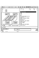
図3に示す画像処理部35は、シミュレーション部31による各境界点の算出結果を表示するための画像データを生成する。表示部46は、画像データに従って、各境界点の算出結果を表示する。図14は、実施の形態2にかかる数値制御装置による境界点の算出結果を表示する画面の例を示す図である。
図14では、加工プログラム21に2つのラベル「LABEL_A」,「LABEL_B」が含まれる場合の例を示す。図14において、「ラベルAの切削範囲」は、「LABEL_A」によって指定される領域Aを表す。「ラベルAの座標データ」は、領域Aの各境界点の座標を表す。「ラベルBの切削範囲」は、「LABEL_B」によって指定される領域Bを表す。「ラベルBの座標データ」は、領域Bの各境界点の座標を表す。表示部46は、各境界点の算出結果をラベルごとに区別して表示する。
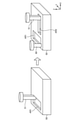
図15は、実施の形態2にかかる数値制御装置において加工プログラムとロボットプログラムとを実行した場合における工作機械およびロボットの動作について説明するための図である。実施の形態2では、数値制御装置1は、複数の系統を有する。複数の系統の各々は、NCプログラムを実行するための処理系統である。数値制御装置1は、加工プログラム21とロボットプログラム22とを互いに異なる系統において実行する。以下の説明において、加工プログラム21を実行する系統を第1の系統、ロボットプログラム22を実行する系統を第2の系統と称することがある。なお、図15において、領域AR1は領域A、領域AR2は領域Bを表す。
工作機械2が加工工具51による領域AR1の切削加工を行っている間は、ロボット3は、ロボットプログラム22に含まれる追加工待機指令に従って、領域AR1におけるバリ取りのための追加工を待機する。ロボット3は、加工プログラム21のうち領域AR1について加工範囲の終了を指定するための指令が実行されるまで、追加工を待機する。
領域AR1についての切削加工が完了し、領域AR1について加工範囲の終了を指定するための指令が実行されると、ロボット3は、ロボット工具60による領域AR1のバリ取りを開始する。領域AR1のバリ取りと並行して、工作機械2は、領域AR2の切削加工を行う。このように、数値制御装置1は、領域AR1の切削加工が完了するまで領域AR1のバリ取りを待機させる。また、数値制御装置1は、領域AR1の切削加工が完了した後は、領域AR1のバリ取りと領域AR2の切削加工とを並行して実施する。
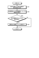
次に、ロボットプログラム生成処理部17の各機能部における処理の手順について説明する。図16は、実施の形態2にかかる数値制御装置が有する加工プログラム解析部による処理手順を示すフローチャートである。ステップS41において、加工プログラム解析部30は、加工プログラム21のうち読み出されたブロックが、ロボット3による加工範囲の開始を指定するための指令か否かを判断する。
読み出されたブロックが加工範囲の開始を指定するための指令である場合(ステップS41,Yes)、加工プログラム解析部30は、ステップS42において、プログラム生成のモードを、ラベル付けを有効とするモードへ切り換える。ラベル付けを有効とするモードにおいて、加工プログラム解析部30は、指令位置および指令速度の解析結果に上記ラベルを付与する。
一方、読み出されたブロックが加工範囲の開始を指定するための指令ではない場合(ステップS41,No)、加工プログラム解析部30は、ステップS43において、加工プログラム21のうち読み出されたブロックが、ロボット3による加工範囲の終了を指定するための指令か否かを判断する。
読み出されたブロックが加工範囲の終了を指定するための指令である場合(ステップS43,Yes)、加工プログラム解析部30は、ステップS44において、プログラム生成のモードを、ラベル付けを無効とするモードへ切り換える。ラベル付けを無効とするモードにおいて、加工プログラム解析部30は、指令位置および指令速度の解析結果への上記ラベルの付与を行わない。
一方、読み出されたブロックが加工範囲の終了を指定するための指令ではない場合(ステップS43,No)、加工プログラム解析部30は、ステップS45において、現在のプログラム生成のモードが、ラベル付けを有効とするモードか否かを判断する。現在のプログラム生成のモードが、ラベル付けを有効とするモードである場合(ステップS45,Yes)、ステップS46において、加工プログラム解析部30は、ラベル付きの解析結果をシミュレーション部31へ出力する。現在のプログラム生成のモードが、ラベル付けを無効とするモードである場合(ステップS45,No)、ステップS47において、加工プログラム解析部30は、ラベル無しの解析結果をシミュレーション部31へ出力する。ステップS42、ステップS44、ステップS46またはステップS47の実行により、加工プログラム解析部30は、図16に示す手順による動作を終了する。
図17は、実施の形態2にかかる数値制御装置が有する補間点算出部による処理手順を示すフローチャートである。ステップS51において、補間点算出部33は、指令位置および指令速度の解析結果を加工プログラム解析部30から取得する。ステップS52において、補間点算出部33は、直進駆動および回転駆動についての各補間点を算出する。
ステップS53において、補間点算出部33は、ステップS51において取得された解析結果が、ラベル付きの解析結果か否かを判断する。取得された解析結果がラベル付きの解析結果である場合(ステップS53,Yes)、ステップS54において、補間点算出部33は、算出された補間点の座標にラベルを紐付けする。補間点算出部33は、ラベルが紐付けされた補間点の座標を境界点算出部34へ出力する。
一方、取得された解析結果がラベル付きの解析結果ではない場合(ステップS53,No)、補間点算出部33は、ステップS54をスキップする。補間点算出部33は、ラベルが紐付けられていない補間点の座標を境界点算出部34へ出力する。ステップS54の実行により、またはステップS54のスキップにより、補間点算出部33は、図17に示す手順による処理を終了する。
図18は、実施の形態2にかかる数値制御装置が有する境界点算出部による処理手順を示すフローチャートである。ステップS61において、境界点算出部34は、各補間点の座標を補間点算出部33から取得する。ステップS62において、境界点算出部34は、工作機械データ23および加工工具データ25を記憶部20から読み出す。
ステップS63において、境界点算出部34は、各補間点の座標と工作機械データ23と加工工具データ25とを基に、単位時間ごとにおける加工工具位置を算出する。ステップS64において、境界点算出部34は、ワークデータ24を記憶部20から読み出す。ステップS65において、境界点算出部34は、算出された加工工具位置とワークデータ24とを基に、ワーク50のうち切削によって除去される領域を算出する。
ステップS66において、境界点算出部34は、ワーク50の切削があるか否かを判定する。ワーク50の切削がある場合(ステップS66,Yes)、ステップS67において、境界点算出部34は、算出された加工工具位置についての境界点の座標を算出する。境界点算出部34は、単位時間ごとの各加工工具位置について、ステップS66による判定を実行するとともに境界点の座標を算出する。ステップS68において、境界点算出部34は、算出された境界点の座標に時系列データを紐付けする。
ステップS69において、境界点算出部34は、算出された境界点が、ラベル付きの補間点についての境界点か否かを判断する。算出された境界点が、ラベル付きの補間点についての境界点である場合(ステップS69,Yes)、ステップS70において、境界点算出部34は、算出された境界点の座標にラベルを紐付けする。境界点算出部34は、ラベルと時系列データとが紐付けされた境界点の座標をロボットプログラム生成部32へ出力する。
一方、算出された境界点が、ラベル付きの補間点についての境界点ではない場合(ステップS69,No)、境界点算出部34は、ステップS70をスキップする。境界点算出部34は、時系列データとラベルとのうち時系列データのみが紐付けられた境界点の座標をロボットプログラム生成部32へ出力する。ステップS70の実行により、またはステップS70のスキップにより、境界点算出部34は、図18に示す手順による処理を終了する。または、ワーク50の切削がない場合(ステップS66,No)、境界点算出部34は、図18に示す手順による処理を終了する。
図19は、実施の形態2にかかる数値制御装置が有するロボットプログラム生成部による処理手順を示すフローチャートである。ステップS81において、ロボットプログラム生成部32は、切削により除去される領域における複数の境界点について、境界点の座標と、当該座標に紐付けられている時系列データとを取得する。
ステップS82において、ロボットプログラム生成部32は、ステップS81において取得された境界点が、ラベル付きの境界点か否かを判断する。境界点がラベル付きの境界点ではない場合(ステップS82,No)、ロボットプログラム生成部32は、手順をステップS86へ進める。
一方、境界点がラベル付きの境界点である場合(ステップS82,Yes)、ステップS83において、ロボットプログラム生成部32は、前回の境界点がラベル無しの境界点か否かを判断する。前回の境界点とは、ステップS81において取得された境界点の1つ前にロボットプログラム生成部32において取得された境界点とする。前回の境界点がラベル無しの境界点である場合(ステップS83,Yes)、ロボットプログラム生成部32は、手順をステップS85へ進める。
一方、前回の境界点がラベル無しの境界点ではなかった場合(ステップS83,No)、ステップS84において、ロボットプログラム生成部32は、ステップS81において取得された境界点のラベルが、前回の境界点のラベルとは異なるか否かを判断する。ステップS81において取得された境界点のラベルが、前回の境界点のラベルと同じである場合(ステップS84,No)、ロボットプログラム生成部32は、手順をステップS86へ進める。一方、ステップS81において取得された境界点のラベルが、前回の境界点のラベルと異なる場合(ステップS84,Yes)、ロボットプログラム生成部32は、手順をステップS85へ進める。
ステップS85において、ロボットプログラム生成部32は、ステップS81において取得された境界点のラベルに対応する追加工待機指令をロボットプログラム22に追加する。ロボットプログラム生成部32は、ステップS85の実行により、手順をステップS86へ進める。
ステップS86において、ロボットプログラム生成部32は、ロボット工具データ26を記憶部20から読み出す。ステップS87において、ロボットプログラム生成部32は、ステップS81にて読み出された境界点の座標を時系列にソートする。ステップS88において、ロボットプログラム生成部32は、各境界点の時系列に従って、各境界点を通る経路に沿ってロボット工具を移動させるためのロボット指令を生成する。当該経路では、境界点同士が直線によって繋がれる。ステップS89において、ロボットプログラム生成部32は、ステップS88にて生成されたロボット指令をロボットプログラム22に追加する。これにより、ロボットプログラム生成部32は、図19に示す手順による処理を終了する。
数値制御装置1は、第1の系統では加工プログラム21を実行し、第2の系統ではロボットプログラム22を実行する。これにより、制御システムは、工作機械2による切削加工とロボット3による追加工とを同時に行う。
図20は、実施の形態2にかかる数値制御装置が加工プログラムまたはロボットプログラムを自動起動した際における数値制御装置の動作手順を示すフローチャートである。ステップS91において、プログラム解析部14は、現在の解析対象であるプログラムが加工プログラム21であるか否かを判断する。
解析対象が加工プログラム21である場合(ステップS91,Yes)、プログラム解析部14は、ステップS92において加工プログラム21を解析する。ステップS94において、プログラム解析部14は、実行されるブロックが、ロボット3による加工範囲の終了を指定するための指令のブロックか否かを判断する。
実行されるブロックが、加工範囲の終了を指定するための指令のブロックである場合(ステップS94,Yes)、ステップS95において、プログラム解析部14は、終了した加工範囲に対応するラベルをメモする。ここでは、プログラム解析部14は、当該加工範囲の切削加工が終了したことを示すラベルを残す。ロボット3は、追加工を行う際に、追加工の対象である加工範囲において追加工の前提である切削加工が終了しているか否かを、かかるラベルに基づいて判断する。一方、実行されるブロックが、加工範囲の終了を指定するための指令のブロックではない場合(ステップS94,No)、プログラム解析部14は、ステップS95をスキップする。プログラム解析部14は、解析結果を補間処理部27へ出力する。ステップS95の実行またはステップS95のスキップにより、数値制御装置1は、手順をステップS96へ進める。
ステップS96において、補間処理部27は、補間点を生成するための補間処理を実行する。ステップS97において、加減速処理部28は、加減速処理を実行する。軸指令出力部29は、加減速処理後の補間結果を基に、加工工具の直進駆動についての移動指令とワーク50の回転駆動についての移動指令とを生成する。ステップS98において、軸指令出力部29は、ドライブコントローラ41へ生成された移動指令を出力する。
一方、解析対象が加工プログラム21ではない場合(ステップS91,No)、すなわち加工対象がロボットプログラム22である場合、プログラム解析部14は、ステップS93においてロボットプログラム22を解析する。ステップS99において、プログラム解析部14は、実行されるブロックが、追加工待機指令のブロックか否かを判断する。実行されるブロックが、追加工待機指令のブロックではない場合(ステップS99,No)、数値制御装置1は、ステップS100をスキップして、手順をステップS101へ進める。
一方、実行されるブロックが、追加工待機指令のブロックである場合(ステップS99,Yes)、ステップS100において、プログラム解析部14は、加工範囲の終了を指定するための指令のブロックが実行済みか否かを判断する。加工範囲の終了を指定するための指令のブロックが実行済みである場合(ステップS100,Yes)、数値制御装置1は、手順をステップS101へ進める。一方、加工範囲の終了を指定するための指令のブロックが実行済みではない場合(ステップS100,No)、数値制御装置1は、加工範囲の終了を指定するための指令が実行されるまでステップS100における判断を繰り返す。プログラム解析部14は、解析結果をロボット制御部16へ出力する。
ロボット制御部16は、解析結果を基に、ロボットコントローラ4が解釈可能な形式のロボット指令を生成する。ステップS101において、ロボット制御部16は、ロボットコントローラ4へ生成されたロボット指令を出力する。ステップS98またはステップS101の実行により、数値制御装置1は、図20に示す手順による動作を終了する。プログラム解析部14は、上記のステップS95において残されたラベルに示される加工範囲までの切削加工が完了したか否かを、ステップS99,S100において判断する。数値制御装置1は、当該加工範囲までの切削加工が完了している場合に、当該加工範囲までの追加工を開始する。
実施の形態2によると、数値制御装置1は、切削加工が施される領域の切削が完了するまで、ロボット3による当該領域のバリ取りを待機させる。また、数値制御装置1は、ロボット3による当該領域のバリ取りと、当該領域の次に切削加工が施される領域における工作機械2による切削とを並行して行わせることができる。制御システムは、ワーク50全体の切削加工が終了するよりも前において、切削が終了した領域からバリ取りを開始できることから、加工時間を短縮することができる。
以上の各実施の形態に示した構成は、本開示の内容の一例を示すものである。各実施の形態の構成は、別の公知の技術と組み合わせることが可能である。各実施の形態の構成同士が適宜組み合わせられても良い。本開示の要旨を逸脱しない範囲で、各実施の形態の構成の一部を省略または変更することが可能である。
1 数値制御装置、2 工作機械、3 ロボット、4 ロボットコントローラ、5 入力操作部、6 入出力ユニット、7 操作盤、8 手動ハンドル、9 非常停止ボタン、10 プロセッサ、11 メモリ、12 記憶装置、13 インタフェース、14 プログラム解析部、15 加工制御部、16 ロボット制御部、17 ロボットプログラム生成処理部、18 入出力処理部、20 記憶部、21 加工プログラム、22 ロボットプログラム、23 工作機械データ、24 ワークデータ、25 加工工具データ、26 ロボット工具データ、27 補間処理部、28 加減速処理部、29 軸指令出力部、30 加工プログラム解析部、31 シミュレーション部、32 ロボットプログラム生成部、33 補間点算出部、34 境界点算出部、35 画像処理部、36 入力制御部、40 駆動部、41 ドライブコントローラ、42 サーボ制御部、43 主軸制御部、44 サーボモータ、45 主軸モータ、46 表示部、47 入力部、48,49 検出器、50 ワーク、51 加工工具、52 上面、53 先端、60 ロボット工具。
Claims (5)
- ワークの切削加工を行う工作機械と、前記ワークのバリ取りのための工具が取り付けられたロボットとを制御する数値制御装置であって、
前記ワークのうち前記切削加工によって除去される領域の境界を示す複数の境界点を、前記切削加工の制御のために実行される加工プログラムの解析結果を基に算出する境界点算出部と、
前記複数の境界点を辿る経路上において前記工具を移動させるためのロボットプログラムを生成するロボットプログラム生成部と、を備えることを特徴とする数値制御装置。 - 前記切削加工のための工具である加工工具の形状についてのデータである加工工具データを保持する記憶部と、
前記加工プログラムの解析結果に基づいて単位時間ごとの前記加工工具の位置を表す補間点を算出する補間点算出部を備え、
前記境界点算出部は、前記加工工具データと複数の前記補間点とに基づいて前記複数の境界点を算出することを特徴とする請求項1に記載の数値制御装置。 - 前記境界点算出部は、前記複数の境界点の各々に切削の順序を表す時系列データを付与し、
前記ロボットプログラム生成部は、前記複数の境界点の各々に付与された前記時系列データによって示される順序で前記複数の境界点の各々を辿る前記経路を設定することを特徴とする請求項1または2に記載の数値制御装置。 - 前記加工プログラムには、前記切削加工が施される加工範囲を指定するための指令が追加可能であって、
前記ロボットプログラム生成部は、前記指令が実行されることによって、前記バリ取りを待機させるための待機指令を前記ロボットプログラムへ追加することを特徴とする請求項1から3のいずれか1つに記載の数値制御装置。 - ワークの切削加工を行う工作機械と、前記ワークのバリ取りのための工具が取り付けられたロボットとを数値制御装置によって制御する数値制御方法であって、
前記ワークのうち前記切削加工によって除去される領域の境界を示す複数の境界点を、前記切削加工の制御のために実行される加工プログラムの解析結果を基に算出する工程と、
前記複数の境界点を辿る経路上において前記工具を移動させるためのロボットプログラムを生成する工程と、を含むことを特徴とする数値制御方法。
Priority Applications (4)
| Application Number | Priority Date | Filing Date | Title |
|---|---|---|---|
| PCT/JP2020/027859 WO2022014042A1 (ja) | 2020-07-17 | 2020-07-17 | 数値制御装置および数値制御方法 |
| DE112020006668.1T DE112020006668T5 (de) | 2020-07-17 | 2020-07-17 | Numerische Steuerungsvorrichtung und numerisches Steuerungsverfahren |
| JP2021506774A JP7004868B1 (ja) | 2020-07-17 | 2020-07-17 | 数値制御装置および数値制御方法 |
| CN202080099251.3A CN115362420B (zh) | 2020-07-17 | 2020-07-17 | 数控装置及数控方法 |
Applications Claiming Priority (1)
| Application Number | Priority Date | Filing Date | Title |
|---|---|---|---|
| PCT/JP2020/027859 WO2022014042A1 (ja) | 2020-07-17 | 2020-07-17 | 数値制御装置および数値制御方法 |
Publications (1)
| Publication Number | Publication Date |
|---|---|
| WO2022014042A1 true WO2022014042A1 (ja) | 2022-01-20 |
Family
ID=79554583
Family Applications (1)
| Application Number | Title | Priority Date | Filing Date |
|---|---|---|---|
| PCT/JP2020/027859 Ceased WO2022014042A1 (ja) | 2020-07-17 | 2020-07-17 | 数値制御装置および数値制御方法 |
Country Status (4)
| Country | Link |
|---|---|
| JP (1) | JP7004868B1 (ja) |
| CN (1) | CN115362420B (ja) |
| DE (1) | DE112020006668T5 (ja) |
| WO (1) | WO2022014042A1 (ja) |
Cited By (2)
| Publication number | Priority date | Publication date | Assignee | Title |
|---|---|---|---|---|
| CN116460935A (zh) * | 2023-04-25 | 2023-07-21 | 华闽搏创(成都)信息科技有限公司 | 基于消除板件移动的保持连接最大化的开料顺序方法 |
| US20230415341A1 (en) * | 2020-11-13 | 2023-12-28 | Fanuc Corporation | Numerical control device and numerical control system |
Citations (4)
| Publication number | Priority date | Publication date | Assignee | Title |
|---|---|---|---|---|
| JP2005031904A (ja) * | 2003-07-10 | 2005-02-03 | Mori Seiki Co Ltd | 自動プログラミング装置 |
| WO2015114734A1 (ja) * | 2014-01-28 | 2015-08-06 | 株式会社牧野フライス製作所 | 切削加工方法および工具経路生成装置 |
| JP2017134722A (ja) * | 2016-01-29 | 2017-08-03 | ファナック株式会社 | 共通の言語仕様のプログラムにて複数の種類の製造装置を駆動する製造システム |
| JP2019086823A (ja) * | 2017-11-01 | 2019-06-06 | ファナック株式会社 | 加工システム |
Family Cites Families (14)
| Publication number | Priority date | Publication date | Assignee | Title |
|---|---|---|---|---|
| JPS62251044A (ja) * | 1986-04-23 | 1987-10-31 | Fanuc Ltd | 4軸旋盤のncプログラム作成方法 |
| JPH07112346A (ja) * | 1993-10-18 | 1995-05-02 | Fanuc Ltd | ロボットによるバリ取り作業の動作プログラム作成方法 |
| JP2006048244A (ja) * | 2004-08-02 | 2006-02-16 | Fanuc Ltd | 加工プログラム作成装置 |
| JP5593899B2 (ja) | 2010-07-12 | 2014-09-24 | 株式会社Ihi | ロボットによるバリ除去方法 |
| US9573202B2 (en) * | 2012-03-30 | 2017-02-21 | Makino Milling Machine Co., Ltd. | Workpiece machining method, machine tool, tool path-generating device and tool path-generating program |
| DE112012006923B4 (de) * | 2012-10-31 | 2016-03-17 | Mitsubishi Electric Corporation | Automatik-Programmiervorrichtung und Verfahren |
| JP5845212B2 (ja) * | 2013-06-28 | 2016-01-20 | ファナック株式会社 | 視覚センサ及び力センサを備えたバリ取り装置 |
| JP6325509B2 (ja) * | 2015-11-11 | 2018-05-16 | ファナック株式会社 | 工作機械 |
| WO2018122986A1 (ja) * | 2016-12-27 | 2018-07-05 | 三菱電機株式会社 | 加工プログラム分析装置 |
| JP6794051B2 (ja) * | 2017-02-22 | 2020-12-02 | ジヤトコ株式会社 | バリ取り方法、バリ取り装置の制御装置、バリ取り装置用の制御プログラム |
| JP6445070B2 (ja) * | 2017-03-27 | 2018-12-26 | ファナック株式会社 | 工作機械の制御システム |
| JP2020019126A (ja) * | 2018-08-03 | 2020-02-06 | 株式会社不二越 | 自動バリ取りおよび/またはエッジ仕上げ装置、ならびにバリ取りおよび/またはエッジ仕上げの自動化方法 |
| CN111085774B (zh) * | 2018-10-24 | 2022-01-25 | 大族激光科技产业集团股份有限公司 | 一种快速寻边方法 |
| WO2020144772A1 (ja) * | 2019-01-09 | 2020-07-16 | 三菱電機株式会社 | 数値制御装置および数値制御方法 |
-
2020
- 2020-07-17 DE DE112020006668.1T patent/DE112020006668T5/de active Pending
- 2020-07-17 JP JP2021506774A patent/JP7004868B1/ja active Active
- 2020-07-17 CN CN202080099251.3A patent/CN115362420B/zh active Active
- 2020-07-17 WO PCT/JP2020/027859 patent/WO2022014042A1/ja not_active Ceased
Patent Citations (4)
| Publication number | Priority date | Publication date | Assignee | Title |
|---|---|---|---|---|
| JP2005031904A (ja) * | 2003-07-10 | 2005-02-03 | Mori Seiki Co Ltd | 自動プログラミング装置 |
| WO2015114734A1 (ja) * | 2014-01-28 | 2015-08-06 | 株式会社牧野フライス製作所 | 切削加工方法および工具経路生成装置 |
| JP2017134722A (ja) * | 2016-01-29 | 2017-08-03 | ファナック株式会社 | 共通の言語仕様のプログラムにて複数の種類の製造装置を駆動する製造システム |
| JP2019086823A (ja) * | 2017-11-01 | 2019-06-06 | ファナック株式会社 | 加工システム |
Cited By (2)
| Publication number | Priority date | Publication date | Assignee | Title |
|---|---|---|---|---|
| US20230415341A1 (en) * | 2020-11-13 | 2023-12-28 | Fanuc Corporation | Numerical control device and numerical control system |
| CN116460935A (zh) * | 2023-04-25 | 2023-07-21 | 华闽搏创(成都)信息科技有限公司 | 基于消除板件移动的保持连接最大化的开料顺序方法 |
Also Published As
| Publication number | Publication date |
|---|---|
| DE112020006668T5 (de) | 2023-04-06 |
| JP7004868B1 (ja) | 2022-02-07 |
| CN115362420B (zh) | 2024-07-30 |
| CN115362420A (zh) | 2022-11-18 |
| JPWO2022014042A1 (ja) | 2022-01-20 |
Similar Documents
| Publication | Publication Date | Title |
|---|---|---|
| CN104412185B (zh) | 用于根据轮廓的图案控制机器的方法和激光切割机 | |
| JP5414948B1 (ja) | 数値制御装置 | |
| JP6719790B1 (ja) | Cadデータによるマシニングセンタの自動運転装置 | |
| WO1989006174A1 (fr) | Dispositif laser pour l'usinage tridimensionnel | |
| JP2019082852A (ja) | ポストプロセッサ装置、加工プログラム生成方法、cnc加工システム及び加工プログラム生成用プログラム | |
| JP2019082851A (ja) | 数値制御装置、cnc工作機械、数値制御方法及び数値制御用プログラム | |
| JPWO2013145275A1 (ja) | ワーク加工面表示方法、ワーク加工面表示装置、工具経路生成装置およびワーク加工面表示プログラム | |
| JP7004868B1 (ja) | 数値制御装置および数値制御方法 | |
| WO2014196066A1 (ja) | 数値制御装置 | |
| JPH09507439A (ja) | 対話形機械制御装置及び方法 | |
| JPS61156309A (ja) | 速度段差平滑機能を備えた数値制御装置 | |
| JP6638979B2 (ja) | 加工工程管理機能付き数値制御装置および加工工程管理プログラム | |
| US20220342381A1 (en) | Managing a machine tool method, for example method of mapping toolpath data and machine code, a control device, and a machine tool | |
| TWI684841B (zh) | 加工傾斜平面的多軸工具機的程式碼產生方法及其裝置 | |
| JP6935606B1 (ja) | 情報処理装置および情報処理プログラム | |
| JP2005321890A (ja) | 誤加工防止装置および誤加工防止方法 | |
| JP7440614B2 (ja) | プログラム解析装置及び制御システム | |
| JP7175340B2 (ja) | 工作機械、情報処理装置および情報処理プログラム | |
| JP3955776B2 (ja) | 数値制御工作機械と数値制御工作機械のデータ変換方法 | |
| WO2026094206A1 (ja) | ロボットプログラミング装置 | |
| JP2003295917A (ja) | 加工制御装置 | |
| JP2779796B2 (ja) | 数値制御装置 | |
| Brecher et al. | Numerical Controllers | |
| JP2694639B2 (ja) | 数値制御装置 | |
| JP2017146910A (ja) | データ生成プログラム、加工装置、及び検査装置 |
Legal Events
| Date | Code | Title | Description |
|---|---|---|---|
| ENP | Entry into the national phase |
Ref document number: 2021506774 Country of ref document: JP Kind code of ref document: A |
|
| 121 | Ep: the epo has been informed by wipo that ep was designated in this application |
Ref document number: 20944912 Country of ref document: EP Kind code of ref document: A1 |
|
| 122 | Ep: pct application non-entry in european phase |
Ref document number: 20944912 Country of ref document: EP Kind code of ref document: A1 |