WO2022013976A1 - 冷凍装置の室外機およびそれを備える冷凍装置 - Google Patents
冷凍装置の室外機およびそれを備える冷凍装置 Download PDFInfo
- Publication number
- WO2022013976A1 WO2022013976A1 PCT/JP2020/027522 JP2020027522W WO2022013976A1 WO 2022013976 A1 WO2022013976 A1 WO 2022013976A1 JP 2020027522 W JP2020027522 W JP 2020027522W WO 2022013976 A1 WO2022013976 A1 WO 2022013976A1
- Authority
- WO
- WIPO (PCT)
- Prior art keywords
- heat exchanger
- refrigerant
- compressor
- expansion valve
- outdoor unit
- Prior art date
- Legal status (The legal status is an assumption and is not a legal conclusion. Google has not performed a legal analysis and makes no representation as to the accuracy of the status listed.)
- Ceased
Links
Images


Classifications
-
- F—MECHANICAL ENGINEERING; LIGHTING; HEATING; WEAPONS; BLASTING
- F25—REFRIGERATION OR COOLING; COMBINED HEATING AND REFRIGERATION SYSTEMS; HEAT PUMP SYSTEMS; MANUFACTURE OR STORAGE OF ICE; LIQUEFACTION SOLIDIFICATION OF GASES
- F25B—REFRIGERATION MACHINES, PLANTS OR SYSTEMS; COMBINED HEATING AND REFRIGERATION SYSTEMS; HEAT PUMP SYSTEMS
- F25B7/00—Compression machines, plants or systems, with cascade operation, i.e. with two or more circuits, the heat from the condenser of one circuit being absorbed by the evaporator of the next circuit
-
- F—MECHANICAL ENGINEERING; LIGHTING; HEATING; WEAPONS; BLASTING
- F25—REFRIGERATION OR COOLING; COMBINED HEATING AND REFRIGERATION SYSTEMS; HEAT PUMP SYSTEMS; MANUFACTURE OR STORAGE OF ICE; LIQUEFACTION SOLIDIFICATION OF GASES
- F25B—REFRIGERATION MACHINES, PLANTS OR SYSTEMS; COMBINED HEATING AND REFRIGERATION SYSTEMS; HEAT PUMP SYSTEMS
- F25B13/00—Compression machines, plants or systems, with reversible cycle
-
- F—MECHANICAL ENGINEERING; LIGHTING; HEATING; WEAPONS; BLASTING
- F25—REFRIGERATION OR COOLING; COMBINED HEATING AND REFRIGERATION SYSTEMS; HEAT PUMP SYSTEMS; MANUFACTURE OR STORAGE OF ICE; LIQUEFACTION SOLIDIFICATION OF GASES
- F25B—REFRIGERATION MACHINES, PLANTS OR SYSTEMS; COMBINED HEATING AND REFRIGERATION SYSTEMS; HEAT PUMP SYSTEMS
- F25B31/00—Compressor arrangements
- F25B31/006—Cooling of compressor or motor
-
- F—MECHANICAL ENGINEERING; LIGHTING; HEATING; WEAPONS; BLASTING
- F25—REFRIGERATION OR COOLING; COMBINED HEATING AND REFRIGERATION SYSTEMS; HEAT PUMP SYSTEMS; MANUFACTURE OR STORAGE OF ICE; LIQUEFACTION SOLIDIFICATION OF GASES
- F25B—REFRIGERATION MACHINES, PLANTS OR SYSTEMS; COMBINED HEATING AND REFRIGERATION SYSTEMS; HEAT PUMP SYSTEMS
- F25B47/00—Arrangements for preventing or removing deposits or corrosion, not provided for in another subclass
- F25B47/02—Defrosting cycles
- F25B47/022—Defrosting cycles hot gas defrosting
- F25B47/025—Defrosting cycles hot gas defrosting by reversing the cycle
-
- F—MECHANICAL ENGINEERING; LIGHTING; HEATING; WEAPONS; BLASTING
- F25—REFRIGERATION OR COOLING; COMBINED HEATING AND REFRIGERATION SYSTEMS; HEAT PUMP SYSTEMS; MANUFACTURE OR STORAGE OF ICE; LIQUEFACTION SOLIDIFICATION OF GASES
- F25B—REFRIGERATION MACHINES, PLANTS OR SYSTEMS; COMBINED HEATING AND REFRIGERATION SYSTEMS; HEAT PUMP SYSTEMS
- F25B49/00—Arrangement or mounting of control or safety devices
- F25B49/02—Arrangement or mounting of control or safety devices for compression type machines, plants or systems
-
- F—MECHANICAL ENGINEERING; LIGHTING; HEATING; WEAPONS; BLASTING
- F25—REFRIGERATION OR COOLING; COMBINED HEATING AND REFRIGERATION SYSTEMS; HEAT PUMP SYSTEMS; MANUFACTURE OR STORAGE OF ICE; LIQUEFACTION SOLIDIFICATION OF GASES
- F25B—REFRIGERATION MACHINES, PLANTS OR SYSTEMS; COMBINED HEATING AND REFRIGERATION SYSTEMS; HEAT PUMP SYSTEMS
- F25B2313/00—Compression machines, plants or systems with reversible cycle not otherwise provided for
- F25B2313/025—Compression machines, plants or systems with reversible cycle not otherwise provided for using multiple outdoor units
- F25B2313/0254—Compression machines, plants or systems with reversible cycle not otherwise provided for using multiple outdoor units in series arrangements
-
- F—MECHANICAL ENGINEERING; LIGHTING; HEATING; WEAPONS; BLASTING
- F25—REFRIGERATION OR COOLING; COMBINED HEATING AND REFRIGERATION SYSTEMS; HEAT PUMP SYSTEMS; MANUFACTURE OR STORAGE OF ICE; LIQUEFACTION SOLIDIFICATION OF GASES
- F25B—REFRIGERATION MACHINES, PLANTS OR SYSTEMS; COMBINED HEATING AND REFRIGERATION SYSTEMS; HEAT PUMP SYSTEMS
- F25B2700/00—Sensing or detecting of parameters; Sensors therefor
- F25B2700/19—Pressures
- F25B2700/195—Pressures of the condenser
-
- F—MECHANICAL ENGINEERING; LIGHTING; HEATING; WEAPONS; BLASTING
- F25—REFRIGERATION OR COOLING; COMBINED HEATING AND REFRIGERATION SYSTEMS; HEAT PUMP SYSTEMS; MANUFACTURE OR STORAGE OF ICE; LIQUEFACTION SOLIDIFICATION OF GASES
- F25B—REFRIGERATION MACHINES, PLANTS OR SYSTEMS; COMBINED HEATING AND REFRIGERATION SYSTEMS; HEAT PUMP SYSTEMS
- F25B2700/00—Sensing or detecting of parameters; Sensors therefor
- F25B2700/21—Temperatures
- F25B2700/2116—Temperatures of a condenser
- F25B2700/21163—Temperatures of a condenser of the refrigerant at the outlet of the condenser
Definitions
- This disclosure relates to an outdoor unit of a refrigerating device and a refrigerating device including the outdoor unit.
- the refrigerating device is provided with a defrosting mode for melting the frost adhering to the cooler.
- a defrosting method for example, a reverse hot gas defrosting method is known in which the circulation direction of the refrigerant is changed so that the high temperature gas from the compressor is sent to a cooler which normally works as an evaporator by a four-way valve.
- Patent Document 1 discloses a refrigerating apparatus that defrosts by a reverse hot gas defrosting method in a low temperature side cycle of a dual cycle.
- the low temperature side cycle described in Patent Document 1 includes a low temperature side compressor, a low temperature side four-way valve, a low temperature side intermediate cooler, a second low temperature side drawing device, a low temperature side condenser, and a first low temperature side.
- the throttle device and the low temperature side evaporator are connected in series by a pipe to form a refrigerant circulation circuit.
- the low temperature side evaporator and the low temperature side condenser function as a condenser
- the low temperature side intercooler functions as an evaporator.
- the heat exchanger on the low temperature side needs to collect heat from the outside air.
- the outside air temperature is low (for example, the outside air temperature is 0 ° C. or lower)
- the heat exchanger on the low temperature side cannot sufficiently obtain heat from the outside air. In this case, a sufficient defrosting effect cannot be obtained.
- the present disclosure has been made to solve the above problems, and provides an outdoor unit of a freezing device capable of obtaining a defrosting effect even when the outside air temperature is low, and a freezing device including the same.
- the purpose is to do.
- the present disclosure is an outdoor unit of a refrigerating apparatus having a refrigerating mode and a defrosting mode, wherein a first refrigerant is circulated between an indoor unit in which a first expansion valve and a first heat exchanger are connected in series.
- the first refrigeration cycle apparatus includes a first refrigeration cycle apparatus, a second refrigeration cycle apparatus that circulates a second refrigerant, and a cascade heat exchanger that exchanges heat between the first refrigerant and the second refrigerant.
- the first refrigerant flows in the positive direction toward the first expansion valve via the first compressor and the second heat exchanger with the first compressor and the second heat exchanger, and in the defrosting mode, the first The connection destination of the discharge port of the first compressor so that the refrigerant flows from the first compressor to the first heat exchanger and in the opposite direction from the first expansion valve to the first heat exchanger via the second heat exchanger.
- a four-way valve that replaces the connection destination of the suction port of the first compressor, and the second refrigeration cycle device has a second compressor, a third expansion valve, and a third heat exchanger.
- the second refrigerant is circulated in the order of the second compressor, the third heat exchanger, the third expansion valve and the cascade heat exchanger, and the second heat exchanger is arranged to absorb the exhaust heat of the third heat exchanger. ing.
- the second heat exchanger is arranged to absorb the exhaust heat of the third heat exchanger, even when the outside air temperature is low, the second heat exchanger can be used as an evaporator in the defrosting mode. 2 The function of the heat exchanger can be guaranteed and the defrosting effect can be obtained.
- FIG. 1 It is a figure which shows the structure of a refrigerating apparatus. It is a figure which shows the structure of the control device which controls a refrigerating device. It is a figure which shows the flow of the refrigerant in the defrosting mode of a refrigerating apparatus. It is a figure which shows the structure of the integrated heat exchanger used for a refrigerating apparatus. It is a figure which shows the structure of the piping of the integrated heat exchanger used for a refrigerating apparatus. It is a flowchart for demonstrating the control which a control device performs. It is a figure which shows the modification 1 of the integrated heat exchanger. It is a figure which shows the modification 2 of the integrated heat exchanger.
- FIG. 1 is a diagram showing a configuration of a refrigerating apparatus 100 according to the present embodiment.
- the refrigerating apparatus 100 includes an outdoor unit 101, an indoor unit 102, and pipes 27 and 31 connecting the outdoor unit 101 and the indoor unit 102.
- the outdoor unit 101 includes a first refrigeration cycle device 103 on the low temperature side (low source side) and a second refrigeration cycle device 104 on the high temperature side (high source side).
- a dual refrigeration cycle device is configured by the first refrigeration cycle device 103 and the second refrigeration cycle device 104.
- the first refrigerant circulates in the first refrigeration cycle device 103.
- the second refrigerant circulates in the second refrigeration cycle device 104.
- the first refrigerant is CO 2 or the like.
- the second refrigerant is CO 2 , propane, or the like.
- the first refrigerant on the first refrigeration cycle device 103 side and the second refrigerant of the second refrigeration cycle device 104 exchange heat with each other by the cascade heat exchanger 11.
- the cascade heat exchanger 11 may be a heat exchanger included in the first refrigeration cycle device 103, or may be a heat exchanger included in the second refrigeration cycle device 104.
- the indoor unit 102 includes a first expansion valve 3 and a first heat exchanger 4.
- the pipe 28 extending from the first expansion valve 3 is connected to the pipe 27 toward the outdoor unit 101.
- the first expansion valve 3 and the first heat exchanger 4 are connected in series by a pipe 29.
- As the first expansion valve 3 for example, a temperature expansion valve controlled based on the temperature of the refrigerant outlet of the first heat exchanger 4 can be used.
- the pipe 30 extending from the first heat exchanger 4 is connected to the pipe 31 toward the outdoor unit 101.
- the first refrigeration cycle device 103 includes a first compressor 1, a second heat exchanger 2, a four-way valve 7, a refrigerant amount adjusting mechanism 10, and a control device 50.
- the refrigerant amount adjusting mechanism 10 includes a liquid receiver 8, a refrigerant discharge pipes 34 and 35, and a flow rate adjusting valve 45.
- the first compressor 1 and the second heat exchanger 2 are connected to and from the indoor unit 102 so that the first refrigerant circulates.
- the discharge side of the first compressor 1 and the four-way valve 7 are connected by a pipe 21.
- the suction side of the first compressor 1 and the four-way valve 7 are connected by a pipe 33.
- the pipe 32 extending from the four-way valve 7 is connected to the pipe 31 toward the indoor unit 102.
- the second heat exchanger 2 and the four-way valve 7 are connected by a pipe 22.
- a check valve 41 is provided between the second heat exchanger 2 and the cascade heat exchanger 11.
- the second heat exchanger 2 and the check valve 41 are connected by a pipe 23.
- the cascade heat exchanger 11 and the liquid receiver 8 are connected by a pipe 24.
- the second refrigeration cycle device 104 includes a second compressor 9, a third heat exchanger 6, and a third expansion valve 5.
- the second refrigerant circulates in the order of the second compressor 9, the third heat exchanger 6, the third expansion valve 5, and the cascade heat exchanger 11.
- the second compressor 9 and the third heat exchanger 6 are connected by a pipe 47.
- the third heat exchanger 6 and the third expansion valve 5 are connected by a pipe 48.
- the third expansion valve 5 and the cascade heat exchanger 11 are connected by a pipe 49.
- the cascade heat exchanger 11 and the second compressor 9 are connected by a pipe 53.
- the cascade heat exchanger 11 exchanges heat between the first refrigerant and the second refrigerant discharged from the second heat exchanger 2 and flowing into the liquid receiver 8.
- the third heat exchanger 6 functions as a condenser and dissipates heat. Since the refrigerant flowing into the liquid receiver 8 is cooled by the cascade heat exchanger 11, the pressure increase in the liquid receiver 8 is suppressed.
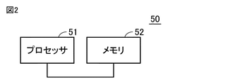
- FIG. 2 is a diagram showing a configuration of a control device 50 that controls a refrigerating device.
- the control device 50 includes a processor 51, a memory 52, a communication interface (not shown), and the like.
- the processor 51 controls the operating frequency of the first compressor 1, the connection of the four-way valve 7, and the like according to the data stored in the memory 52 and the information obtained via the communication interface.
- the memory 52 includes, for example, a ROM (Read Only Memory), a RAM (Random Access Memory), and a flash memory.
- the flash memory stores an operating system, an application program, and various types of data.
- the control device 50 shown in FIG. 1 is realized by the processor 51 executing an operating system and an application program stored in the memory 52. When executing the application program, various data stored in the memory 52 are referred to.
- the refrigerating apparatus 100 has a refrigerating mode and a defrosting mode as operating modes.
- the refrigerant flows in the direction shown by the arrow in FIG.
- FIG. 3 is a diagram showing the flow of the refrigerant in the defrosting mode of the refrigerating apparatus 100.
- the four-way valve 7 swaps the connection destination of the discharge port of the first compressor 1 and the connection destination of the suction port of the first compressor 1 in the refrigeration mode and the defrost mode.
- the four-way valve 7 causes the first refrigerant to flow in the positive direction toward the first expansion valve 3 via the first compressor 1 and the second heat exchanger 2.
- the second refrigeration cycle device 104 continues to operate regardless of whether the operation mode is the refrigeration mode or the defrosting mode.
- the first refrigerant flows from the first compressor 1 to the first heat exchanger 4, and the first expansion valve 3 passes through the second heat exchanger 2.
- the first heat exchanger 4 on the indoor unit 102 side functions as a condenser.
- the second heat exchanger 2 on the outdoor unit 101 side functions as an evaporator and gives heat to the second refrigerant toward the suction side of the first compressor 1.
- the second heat exchanger 2 In the defrosting mode, the second heat exchanger 2 needs to collect heat from the outside air. However, when the outside air temperature is low (for example, 0 ° C. or lower), the second heat exchanger 2 itself may be frosted. Further, even if the second heat exchanger 2 is not frosted, the second heat exchanger 2 may not be able to sufficiently obtain heat from the outside air when the outside air temperature is low. Therefore, in the present disclosure, the second heat exchanger 2 is arranged to absorb the exhaust heat of the third heat exchanger 6. Specifically, the second heat exchanger 2 is provided in the vicinity of the third heat exchanger 6 of the second refrigeration cycle device 104.
- the second heat exchanger 2 Since the second heat exchanger 2 is provided in the vicinity of the third heat exchanger 6, the second heat exchanger that functions as an evaporator (heat collector) in the defrost mode from the exhaust heat of the third heat exchanger 6. 2 can be absorbed. Therefore, even when the outside air temperature is low, the second heat exchanger 2 can effectively function as an evaporator.
- the integrated heat exchanger 260 is configured by the second heat exchanger 2 and the third heat exchanger 6.
- the refrigerant amount adjusting mechanism 10 is configured to adjust the circulation amount of the first refrigerant in both the freezing mode and the defrosting mode.
- the liquid receiver 8 is arranged between the second heat exchanger 2 and the first expansion valve 3.
- the refrigerant discharge pipes 34 and 35 connect between the outlet of the liquid receiver 8 and the suction port of the first compressor 1.
- the flow rate adjusting valve 45 adjusts the flow rate of the first refrigerant flowing through the refrigerant discharge pipes 34 and 35.
- at least the refrigerant amount adjusting mechanism 10 is not an essential configuration.
- the outdoor unit 101 provides bypass flow paths 36 and 37 in which the first refrigerant flows from the first expansion valve 3 toward the second heat exchanger 2 without passing through the liquid receiver 8 in the defrosting mode shown in FIG. Further prepare.
- the outdoor unit 101 is provided in the second expansion valve 46 provided in the bypass flow paths 36 and 37, and is provided in the bypass flow path 37, and allows the refrigerant flow direction to flow from the second expansion valve 46 toward the second heat exchanger 2. It is further provided with a check valve 43 that limits the direction.
- the second expansion valve 46 is an expansion valve for defrosting that functions in the defrosting mode.
- the control device 50 controls the second expansion valve 46 in a closed state in the refrigerating mode. On the other hand, the control device 50 opens the first expansion valve 3 on the indoor unit 102 side in the defrosting mode.
- the refrigerant circulates in the direction shown by the arrow in FIG.
- a sufficient amount of refrigerant is stored in the receiver 8 of the refrigerant amount adjusting mechanism 10.
- the amount of refrigerant circulating when the flow rate adjusting valve 45 is opened is added. Therefore, in order to set the amount of the refrigerant circulating in the defrosting mode to an appropriate amount, the flow rate adjusting valve 45 may be closed when the amount of the refrigerant reaches an appropriate amount.
- the check valve 42 is provided between the pipe 25 and the pipe 26 after the refrigerant discharge pipe 34 is branched, even if the flow rate adjusting valve 45 is opened in the defrosting mode, the first expansion valve 3 is used. The refrigerant does not flow back to the receiver 8 side.
- the second refrigeration cycle device 104 continues to operate even after the operation mode is switched from the refrigeration mode to the defrosting mode.
- the first refrigerant flowing from the second expansion valve 46 to the pipe 23 is divided into the direction of the second heat exchanger 2 and the direction of the cascade heat exchanger 11.
- the first refrigerant directed toward the cascade heat exchanger 11 is cooled by the cascade heat exchanger 11, and a part of the first refrigerant is stored in the liquid receiver 8.
- the control device 50 adjusts the flow rate of the first refrigerant by controlling the flow rate adjusting valve 45.
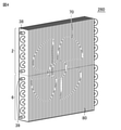
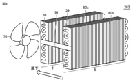
- FIG. 4 is a diagram showing the configurations of the second heat exchanger 2 and the third heat exchanger 6 used in the refrigerating apparatus.
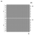
- FIG. 5 is a diagram showing the configuration of the piping of the second heat exchanger 2 and the third heat exchanger 6 used in the refrigerating apparatus.
- the integrated heat exchanger 260 is configured by the second heat exchanger 2 and the third heat exchanger 6.
- the second heat exchanger 2 of the first refrigeration cycle device 103 is arranged at the top
- the third heat exchanger 6 of the second refrigeration cycle device 104 is arranged at the bottom.
- the integrated heat exchanger 260 includes a plurality of fins 80.
- a fan 70 which is commonly used in the second heat exchanger 2 and the third heat exchanger 6, is provided on the back side of the fin 80 toward the drawing. As the fan 70 rotates, an air flow is generated from the fin 80 toward the back side toward the drawing.
- the pipe 38 of the second heat exchanger 2 and the pipe 39 of the third heat exchanger 6 are fixed to the plurality of fins 80 in a meandering manner.
- the integrated heat exchanger 260 has a configuration in which the second heat exchanger 2 is arranged above the third heat exchanger 6, the second heat exchanger 2 is discharged from the third heat exchanger 6 and rises. It is easy to take in the heat of the air. Further, since the fin 80 common to the second heat exchanger 2 and the third heat exchanger 6 is used, the exhaust heat of the third heat exchanger 6 is quickly and efficiently transferred to the second heat exchanger 2. be able to. Therefore, even when the outside air temperature is low, the function of the second heat exchanger 2 as an evaporator in the defrosting mode can be ensured, and the defrosting effect can be obtained.
- the fin 80 is shared between the second heat exchanger 2 and the third heat exchanger 6, but instead of this, the second heat exchanger 2 and the third heat are used. Fins may be provided separately for the exchanger 6. In this way, the heat transfer effect due to the common fins cannot be obtained.
- the second heat exchanger 2 is arranged above the third heat exchanger 6, the second heat exchanger 2 takes the heat of the air discharged from the third heat exchanger 6 and rises. Easy to get in. Therefore, even when the outside air temperature is low, the function of the second heat exchanger 2 as an evaporator in the defrosting mode can be ensured, and the defrosting effect can be obtained.
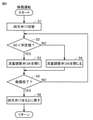
- FIG. 6 is a flowchart for explaining the control executed by the control device.
- the processing of this flowchart is repeatedly executed every time a certain period of time elapses or every time a predetermined condition is satisfied during the operation of the refrigerating apparatus. For example, when defrosting is performed at regular time intervals, the control device 50 executes the process of the flowchart of FIG. 6 when a certain time has elapsed since the previous defrosting of the first heat exchanger 4.
- the determination of the transition to the defrosting mode may be made based on the detection of the refrigerant temperature or the state of frost adhering to the first heat exchanger 4.
- control device 50 switches the four-way valve 7 from the state of FIG. 1 to the state of FIG. 3 in step S1.
- step S2 the control device 50 monitors the outputs of the temperature sensor 61 and the pressure sensor 62, and the degree of supercooling (SC: subcool) of the first refrigerant in the bypass flow path 36 in front of the second expansion valve 46 is determined. Judge whether it is lower than the judgment value.
- SC degree of supercooling
- the control device 50 opens the flow rate adjusting valve 45 in order to add the amount of the refrigerant to be circulated.
- the SC is equal to or higher than the determination value (NO in S2), the amount of the refrigerant to be circulated is sufficient, and the control device 50 closes the flow rate adjusting valve 45.
- steps S2 to S4 are repeated until it is determined in step S5 that the defrosting is completed.
- the amount of the refrigerant circulating in the defrosting mode is adjusted to an appropriate amount.
- step S6 the control device 50 returns the four-way valve 7 to the state of the freezing mode shown in FIG.
- the refrigerating device 100 since the amount of refrigerant circulating during defrosting can be maintained appropriately, it is possible to avoid a decrease in defrosting ability and an excessive increase in high pressure due to a shortage of refrigerant. Therefore, the frost can be reliably melted in a short time, and the design pressure can be kept low.
- the design pressure of the first refrigeration cycle device 103 on the low temperature side is set low. Therefore, adjusting the refrigerant circulation amount in the defrosting mode by the refrigerant amount adjusting mechanism 10 is effective in suppressing the pressure of the first refrigerating cycle device 103 on the low temperature side, and when carbon dioxide gas or the like is applied as the second refrigerant. It is effective for.
- FIG. 7 is a diagram showing a modification 1 of the integrated heat exchanger.
- the integrated heat exchanger 261 has a configuration in which the second heat exchanger 2 and the third heat exchanger 6 are arranged side by side in the horizontal direction.
- the integrated heat exchanger 261 includes a plurality of fins 80 common to the second heat exchanger 2 and the third heat exchanger 6, similar to the integrated heat exchanger 260.
- the integrated heat exchanger 261 includes a fan 70 on the side of the second heat exchanger 2 and the third heat exchanger 6 that is closer to the second heat exchanger 2.
- the fan 70 rotates, an air flow is generated in the direction from the third heat exchanger 6 to the second heat exchanger 2. Since the second heat exchanger 2 is located on the leeward side of the airflow with respect to the third heat exchanger 6, it is easy to take in the heat discharged from the third heat exchanger 6. Further, by using the fin 80 common to the second heat exchanger 2 and the third heat exchanger 6, the exhaust heat of the third heat exchanger 6 is quickly and efficiently transferred to the second heat exchanger 2. It is possible to do. Therefore, in the defrosting mode, the second heat exchanger 2 can quickly and efficiently collect heat.
- the arrangement positions of the second heat exchanger 2 and the third heat exchanger 6 may be reversed.
- the second heat exchanger 2 is located on the wind side of the airflow with respect to the third heat exchanger 6, but the second heat exchanger 2 has the third heat exchanger 6 and the fins 80 in common. , The exhaust heat of the third heat exchanger 6 can be absorbed through the fins 80.
- FIG. 8 is a diagram showing a modification 2 of the integrated heat exchanger.
- the integrated heat exchanger 262 has fins common to the second heat exchanger 2 and the third heat exchanger 6 as compared with the integrated heat exchanger 261 shown in FIG. 7. It differs in that it does not.
- the second heat exchanger 2 and the third heat exchanger 6 are arranged in the horizontal direction, and the second heat exchanger 2 and the third heat exchanger 6 are connected by the connecting member 91. It is connected.
- the rotation of the fan 70 generates an air flow in the direction from the third heat exchanger 6 to the second heat exchanger 2.
- the integrated heat exchanger 262 does not have a heat transfer effect due to the common fins.
- the second heat exchanger 2 is located on the leeward side of the airflow with respect to the third heat exchanger 6, it is easy to take in the heat discharged from the third heat exchanger 6. Therefore, even when the outside air temperature is low, the function of the second heat exchanger 2 as an evaporator in the defrosting mode can be ensured, and the defrosting effect can be obtained.
- the present disclosure is an outdoor unit (101) of a refrigerating apparatus (100) having a refrigerating mode and a defrosting mode, in which a first expansion valve (3) and a first heat exchanger (4) are connected in series. Between the first refrigerating cycle apparatus (103) that circulates the first refrigerant between the machine (102), the second refrigerating cycle apparatus (104) that circulates the second refrigerant, and the first refrigerant and the second refrigerant.
- the first refrigeration cycle apparatus (103) includes the first compressor (1) and the second heat exchanger (2), and the first refrigeration cycle apparatus (103) in the refrigeration mode.
- the refrigerant flows in the positive direction toward the first expansion valve (3) via the first compressor (1) and the second heat exchanger (2), and the first refrigerant is passed through the first compressor (1) in the defrosting mode.
- It has a four-way valve (7) that replaces the connection destination of the discharge port of the machine (1) and the connection destination of the suction port of the first compressor (1), and the second refrigeration cycle device is the second compressor (9).
- a third expansion valve (5), and a third heat exchanger (6), and the second refrigerant is a second compressor (9), a third heat exchanger (6), and a third expansion valve.
- the arrangement configuration is a plurality of pipes (38) in which the first refrigerant flows in the second heat exchanger (2) and the pipes (39) in which the second refrigerant flows in the third heat exchanger (6). It is a configuration in which the fins (80) of the above are connected (see FIGS. 5 and 7).
- the arrangement configuration is such that the second heat exchanger (2) is arranged above the third heat exchanger (6) (see FIG. 4).
- the outdoor unit (101) further includes a fan (70) for blowing air to the second heat exchanger (2) and the third heat exchanger (6), and the arrangement configuration is the second heat exchanger (2). ) Is arranged on the downstream side of the airflow generated by the fan (70) with respect to the third heat exchanger (6) (see FIGS. 7 and 8).
- the outdoor unit (101) further includes a refrigerant amount adjusting mechanism (10) for adjusting the circulation amount of the first refrigerant in the defrosting mode.
- the refrigerant amount adjusting mechanism (10) is a liquid receiver (8) and a liquid receiver (8) arranged between the second heat exchanger (2) and the first expansion valve (3).
- a refrigerant discharge pipe (34, 35) connecting between the outlet and the suction port of the first compressor (1), and a flow control valve for adjusting the flow rate of the first refrigerant flowing through the refrigerant discharge pipe (34, 35).
- the outdoor unit (101) has (45), and in the defrosting mode, the first refrigerant is transferred from the first expansion valve (3) to the second heat exchanger (2) without passing through the liquid receiver (8). ) Is further provided with a bypass flow path (36, 37) flowing toward the).
- the outdoor unit (101) is provided in the second expansion valve (46) provided in the bypass flow path (36, 37) and in the bypass flow path (36, 37), and the refrigerant flow direction is set to the second expansion valve.
- a check valve (43) that limits the flow direction from (46) to the second heat exchanger (2) is further provided.
Landscapes
- Engineering & Computer Science (AREA)
- Physics & Mathematics (AREA)
- Mechanical Engineering (AREA)
- Thermal Sciences (AREA)
- General Engineering & Computer Science (AREA)
- Air Conditioning Control Device (AREA)
- Compression-Type Refrigeration Machines With Reversible Cycles (AREA)
Priority Applications (4)
| Application Number | Priority Date | Filing Date | Title |
|---|---|---|---|
| JP2022536043A JP7391223B2 (ja) | 2020-07-15 | 2020-07-15 | 冷凍装置の室外機およびそれを備える冷凍装置 |
| PCT/JP2020/027522 WO2022013976A1 (ja) | 2020-07-15 | 2020-07-15 | 冷凍装置の室外機およびそれを備える冷凍装置 |
| CN202080102860.XA CN115769032A (zh) | 2020-07-15 | 2020-07-15 | 制冷装置的室外机以及具备该室外机的制冷装置 |
| EP20945538.5A EP4184080A4 (en) | 2020-07-15 | 2020-07-15 | OUTDOOR UNIT FOR REFRIGERATION DEVICE AND REFRIGERATION DEVICE INCLUDING SAME |
Applications Claiming Priority (1)
| Application Number | Priority Date | Filing Date | Title |
|---|---|---|---|
| PCT/JP2020/027522 WO2022013976A1 (ja) | 2020-07-15 | 2020-07-15 | 冷凍装置の室外機およびそれを備える冷凍装置 |
Publications (1)
| Publication Number | Publication Date |
|---|---|
| WO2022013976A1 true WO2022013976A1 (ja) | 2022-01-20 |
Family
ID=79554565
Family Applications (1)
| Application Number | Title | Priority Date | Filing Date |
|---|---|---|---|
| PCT/JP2020/027522 Ceased WO2022013976A1 (ja) | 2020-07-15 | 2020-07-15 | 冷凍装置の室外機およびそれを備える冷凍装置 |
Country Status (4)
| Country | Link |
|---|---|
| EP (1) | EP4184080A4 (enExample) |
| JP (1) | JP7391223B2 (enExample) |
| CN (1) | CN115769032A (enExample) |
| WO (1) | WO2022013976A1 (enExample) |
Cited By (4)
| Publication number | Priority date | Publication date | Assignee | Title |
|---|---|---|---|---|
| WO2024127924A1 (ja) * | 2022-12-12 | 2024-06-20 | ダイキン工業株式会社 | 空調ユニット |
| WO2024161936A1 (ja) * | 2023-02-01 | 2024-08-08 | ダイキン工業株式会社 | 二元冷凍サイクル装置 |
| JP7602156B1 (ja) | 2023-07-03 | 2024-12-18 | ダイキン工業株式会社 | 冷凍装置 |
| WO2025009339A1 (ja) * | 2023-07-03 | 2025-01-09 | ダイキン工業株式会社 | 冷凍装置 |
Citations (3)
| Publication number | Priority date | Publication date | Assignee | Title |
|---|---|---|---|---|
| JP2009299909A (ja) * | 2008-06-10 | 2009-12-24 | Hitachi Appliances Inc | 冷凍サイクル装置 |
| JP2012112617A (ja) * | 2010-11-26 | 2012-06-14 | Mitsubishi Electric Corp | 冷凍装置 |
| US20150338145A1 (en) * | 2014-05-22 | 2015-11-26 | Lg Electronics Inc. | Heat pump |
Family Cites Families (4)
| Publication number | Priority date | Publication date | Assignee | Title |
|---|---|---|---|---|
| JPH07234041A (ja) * | 1994-02-22 | 1995-09-05 | Sanyo Electric Co Ltd | 多元冷凍装置 |
| JP5800842B2 (ja) * | 2013-02-21 | 2015-10-28 | 三菱電機株式会社 | 冷凍装置 |
| CN108444125A (zh) * | 2017-02-16 | 2018-08-24 | 陈则韶 | 第一种重叠循环式供暖热水空调三用机 |
| WO2019008742A1 (ja) * | 2017-07-07 | 2019-01-10 | 三菱電機株式会社 | 冷凍サイクル装置 |
-
2020
- 2020-07-15 WO PCT/JP2020/027522 patent/WO2022013976A1/ja not_active Ceased
- 2020-07-15 JP JP2022536043A patent/JP7391223B2/ja active Active
- 2020-07-15 EP EP20945538.5A patent/EP4184080A4/en not_active Withdrawn
- 2020-07-15 CN CN202080102860.XA patent/CN115769032A/zh active Pending
Patent Citations (4)
| Publication number | Priority date | Publication date | Assignee | Title |
|---|---|---|---|---|
| JP2009299909A (ja) * | 2008-06-10 | 2009-12-24 | Hitachi Appliances Inc | 冷凍サイクル装置 |
| JP2012112617A (ja) * | 2010-11-26 | 2012-06-14 | Mitsubishi Electric Corp | 冷凍装置 |
| JP5595245B2 (ja) | 2010-11-26 | 2014-09-24 | 三菱電機株式会社 | 冷凍装置 |
| US20150338145A1 (en) * | 2014-05-22 | 2015-11-26 | Lg Electronics Inc. | Heat pump |
Non-Patent Citations (1)
| Title |
|---|
| See also references of EP4184080A4 |
Cited By (19)
| Publication number | Priority date | Publication date | Assignee | Title |
|---|---|---|---|---|
| WO2024127924A1 (ja) * | 2022-12-12 | 2024-06-20 | ダイキン工業株式会社 | 空調ユニット |
| JP2024083974A (ja) * | 2022-12-12 | 2024-06-24 | ダイキン工業株式会社 | 空調ユニット |
| JP7518418B2 (ja) | 2022-12-12 | 2024-07-18 | ダイキン工業株式会社 | 空調ユニット |
| WO2024161936A1 (ja) * | 2023-02-01 | 2024-08-08 | ダイキン工業株式会社 | 二元冷凍サイクル装置 |
| JP2024109246A (ja) * | 2023-02-01 | 2024-08-14 | ダイキン工業株式会社 | 二元冷凍サイクル装置 |
| CN120712443A (zh) * | 2023-02-01 | 2025-09-26 | 大金工业株式会社 | 二元冷冻循环装置 |
| EP4431841A4 (en) * | 2023-02-01 | 2025-02-19 | Daikin Industries, Ltd. | TWO-STAGE CASCADE COOLING CYCLE DEVICE |
| JP7614521B2 (ja) | 2023-02-01 | 2025-01-16 | ダイキン工業株式会社 | 二元冷凍サイクル装置 |
| WO2025009297A1 (ja) * | 2023-07-03 | 2025-01-09 | ダイキン工業株式会社 | 冷凍装置 |
| JPWO2025009569A1 (enExample) * | 2023-07-03 | 2025-01-09 | ||
| WO2025009569A1 (ja) * | 2023-07-03 | 2025-01-09 | ダイキン工業株式会社 | 熱源ユニット及び冷凍装置 |
| JP2025007814A (ja) * | 2023-07-03 | 2025-01-17 | ダイキン工業株式会社 | 冷凍装置 |
| JP2025009892A (ja) * | 2023-07-03 | 2025-01-20 | ダイキン工業株式会社 | 冷凍装置 |
| WO2025009339A1 (ja) * | 2023-07-03 | 2025-01-09 | ダイキン工業株式会社 | 冷凍装置 |
| JP7656242B2 (ja) | 2023-07-03 | 2025-04-03 | ダイキン工業株式会社 | 冷凍装置 |
| EP4513108A4 (en) * | 2023-07-03 | 2025-05-21 | Daikin Industries, Ltd. | Heat source unit and refrigeration device |
| EP4513109A4 (en) * | 2023-07-03 | 2025-05-28 | Daikin Industries, Ltd. | COOLING DEVICE |
| JP7727250B2 (ja) | 2023-07-03 | 2025-08-21 | ダイキン工業株式会社 | 熱源ユニット及び冷凍装置 |
| JP7602156B1 (ja) | 2023-07-03 | 2024-12-18 | ダイキン工業株式会社 | 冷凍装置 |
Also Published As
| Publication number | Publication date |
|---|---|
| JPWO2022013976A1 (enExample) | 2022-01-20 |
| EP4184080A4 (en) | 2023-09-13 |
| CN115769032A (zh) | 2023-03-07 |
| JP7391223B2 (ja) | 2023-12-04 |
| EP4184080A1 (en) | 2023-05-24 |
Similar Documents
| Publication | Publication Date | Title |
|---|---|---|
| JP6685409B2 (ja) | 空気調和装置 | |
| CN103822355B (zh) | 热泵式热水供给装置 | |
| JP5992112B2 (ja) | 空気調和装置 | |
| KR101639814B1 (ko) | 냉장 및 냉동 복합 공조시스템 | |
| JP5992089B2 (ja) | 空気調和装置 | |
| WO2022013976A1 (ja) | 冷凍装置の室外機およびそれを備える冷凍装置 | |
| JP5992088B2 (ja) | 空気調和装置 | |
| JP5404761B2 (ja) | 冷凍装置 | |
| JP7105933B2 (ja) | 冷凍装置の室外機およびそれを備える冷凍装置 | |
| JP2015117894A (ja) | 空気調和機の室外機 | |
| WO2021014520A1 (ja) | 空気調和装置 | |
| JP2009243842A (ja) | マルチ型空気調和機および室外機の運転方法 | |
| CN213089945U (zh) | 一种空调装置 | |
| JP2007107771A (ja) | 冷凍サイクル装置 | |
| KR101173736B1 (ko) | 냉장 및 냉동 복합 공조시스템 | |
| CN212362478U (zh) | 制冷系统 | |
| JP4622901B2 (ja) | 空気調和装置 | |
| JP2011133132A (ja) | 冷凍装置 | |
| JP4104519B2 (ja) | 冷凍システム | |
| JP4108003B2 (ja) | 冷凍システム | |
| JP7760076B1 (ja) | 空気調和装置 | |
| CN107238124A (zh) | 一种制热机组及其控制方法 | |
| KR20110085393A (ko) | 공기 조화기 | |
| JP5228661B2 (ja) | 冷凍装置 | |
| WO2024252469A1 (ja) | 冷凍サイクル装置 |
Legal Events
| Date | Code | Title | Description |
|---|---|---|---|
| 121 | Ep: the epo has been informed by wipo that ep was designated in this application |
Ref document number: 20945538 Country of ref document: EP Kind code of ref document: A1 |
|
| ENP | Entry into the national phase |
Ref document number: 2022536043 Country of ref document: JP Kind code of ref document: A |
|
| NENP | Non-entry into the national phase |
Ref country code: DE |
|
| ENP | Entry into the national phase |
Ref document number: 2020945538 Country of ref document: EP Effective date: 20230215 |