WO2022009866A1 - ガスケット、その管理の方法、システムおよびプログラム - Google Patents
ガスケット、その管理の方法、システムおよびプログラム Download PDFInfo
- Publication number
- WO2022009866A1 WO2022009866A1 PCT/JP2021/025408 JP2021025408W WO2022009866A1 WO 2022009866 A1 WO2022009866 A1 WO 2022009866A1 JP 2021025408 W JP2021025408 W JP 2021025408W WO 2022009866 A1 WO2022009866 A1 WO 2022009866A1
- Authority
- WO
- WIPO (PCT)
- Prior art keywords
- gasket
- shape
- load
- information
- inner cut
- Prior art date
- Legal status (The legal status is an assumption and is not a legal conclusion. Google has not performed a legal analysis and makes no representation as to the accuracy of the status listed.)
- Ceased
Links
Images








Classifications
-
- F—MECHANICAL ENGINEERING; LIGHTING; HEATING; WEAPONS; BLASTING
- F16—ENGINEERING ELEMENTS AND UNITS; GENERAL MEASURES FOR PRODUCING AND MAINTAINING EFFECTIVE FUNCTIONING OF MACHINES OR INSTALLATIONS; THERMAL INSULATION IN GENERAL
- F16J—PISTONS; CYLINDERS; SEALINGS
- F16J15/00—Sealings
-
- F—MECHANICAL ENGINEERING; LIGHTING; HEATING; WEAPONS; BLASTING
- F16—ENGINEERING ELEMENTS AND UNITS; GENERAL MEASURES FOR PRODUCING AND MAINTAINING EFFECTIVE FUNCTIONING OF MACHINES OR INSTALLATIONS; THERMAL INSULATION IN GENERAL
- F16J—PISTONS; CYLINDERS; SEALINGS
- F16J15/00—Sealings
- F16J15/02—Sealings between relatively-stationary surfaces
- F16J15/06—Sealings between relatively-stationary surfaces with solid packing compressed between sealing surfaces
- F16J15/10—Sealings between relatively-stationary surfaces with solid packing compressed between sealing surfaces with non-metallic packing
-
- F—MECHANICAL ENGINEERING; LIGHTING; HEATING; WEAPONS; BLASTING
- F16—ENGINEERING ELEMENTS AND UNITS; GENERAL MEASURES FOR PRODUCING AND MAINTAINING EFFECTIVE FUNCTIONING OF MACHINES OR INSTALLATIONS; THERMAL INSULATION IN GENERAL
- F16L—PIPES; JOINTS OR FITTINGS FOR PIPES; SUPPORTS FOR PIPES, CABLES OR PROTECTIVE TUBING; MEANS FOR THERMAL INSULATION IN GENERAL
- F16L23/00—Flanged joints
- F16L23/02—Flanged joints the flanges being connected by members tensioned axially
-
- G—PHYSICS
- G01—MEASURING; TESTING
- G01L—MEASURING FORCE, STRESS, TORQUE, WORK, MECHANICAL POWER, MECHANICAL EFFICIENCY, OR FLUID PRESSURE
- G01L5/00—Apparatus for, or methods of, measuring force, work, mechanical power, or torque, specially adapted for specific purposes
Definitions
- the present disclosure relates to, for example, gaskets used for fastening piping systems and management techniques thereof.
- Tightening torque and bolt axial force value applied to the flange by the bolt are traditionally used. Tightening torque and bolt axial force value are tightening information about bolts that tighten between flanges.
- Tightening torque and bolt axial force value are tightening information about bolts that tighten between flanges.
- Patent Document 1 a system using information on the tightening surface pressure corresponding to the type of gasket and internal fluid, a plurality of tightening forces, bolts, etc. is known (for example, Patent Document 1).
- Patent Document 2 Regarding the tightening of bolts, it is known that the strain generated in the bolts is converted into data and the tightened state of the bolts is visualized.
- a sheet type pressure sensor embedded inside the gasket is known to measure the force applied to a part of the gasket by fastening (for example, Patent Document 3).
- the reason why the bolt tightening torque and axial force value are used for gasket tightening management is that the bolt is a means of tightening between flanges, and that the tightening force from the bolt can be easily grasped by measuring the bolt strain. be.
- the tightening force of the bolt acts on the flange, and the gasket merely acts indirectly through the flange. That is, the flange receives a load due to the tightening of the bolt, and this load merely acts on the gasket through the flange.
- the torque value and the axial force value applied to the bolt are the loads acting on a part of the flange, and cannot be said to represent the surface pressure acting on the gasket.
- the torque value and axial force value obtained from the bolt are information about the bolt, and it cannot be said that the surface pressure received by the gasket is measured.
- the torque value and axial force value of the bolt are only indirect information and are only a guideline for the surface pressure.
- Patent Documents 1 to 3 do not disclose or suggest such a problem. Further, such a problem cannot be solved by the configurations disclosed in Patent Documents 1 to 3.
- the purpose of the present disclosure is to directly observe the shape change of the gasket that receives the load between the flanges based on the above-mentioned problems and the above-mentioned findings, and to improve the gasket and its management technique by using the observation result for the management of the tightening of the gasket. It is to plan.
- the non-constrained portion adjacent to the restrained portion constrained between the flanges is provided with an inner cut, and the inner cut is provided by the load applied to the restrained portion.
- the shape of is changed.
- the minimum point information can be further obtained from the shape change of the inner cut.
- the step of installing a gasket having an inner cut whose shape changes under load, and the flange being restrained between the flanges is managed based on the shape.
- This management method may further include a step of acquiring minimum point information from the shape change of the inner cut.
- a measuring means for measuring the shape of the inner cut formed on the peripheral edge of the gasket, and management information for managing the tightening of the gasket based on the shape includes a management server that generates the above, and an information presentation unit that presents the management information.
- the program of the present disclosure is a program to be realized by a computer, and the shape information of the inner cut provided in the gasket which is restrained between the flanges and receives a load is acquired.
- the computer realizes a function, a function of generating management information for managing the tightening of the gasket based on the shape information, and a function of presenting the management information.
- the computer further realizes a function of acquiring minimum point information from the shape change of the inner cut.
- A is a plan view showing a gasket according to the first embodiment
- B is an enlarged perspective view showing an IB portion of A.
- It is a figure which shows the flange fastening part which concerns on 1st Embodiment.
- A is a diagram showing an enlarged inner cut
- B is a diagram showing a change in the shape of the inner cut.
- A, B and C are diagrams showing a modified example of the inner cut.
- It is a figure which shows the gasket management system which concerns on 1st Embodiment.
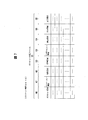
- It is a figure which shows the gasket management database.
- A is a diagram showing a comparative example
- B is a diagram showing the setting of the shape observation unit.
- A is a diagram showing the shape of the gasket according to the fifth embodiment
- B is a diagram showing an example of a state before a load is applied
- C is a diagram showing an example of a state when a load of a predetermined value is applied. It is a figure which shows the shape observation example which concerns on Example 5.
- FIG. 1 shows the gasket 2 according to the first embodiment.
- the configuration shown in FIG. 1 is an example, and the present disclosure is not limited to such a configuration.
- the X-axis, the Y-axis, and the Z-axis are shown together as an example.
- This gasket 2 is, for example, a sheet gasket processed with a material containing a polytetrafluoroethylene resin (PTFE: Polytetrafluoroethylene) and a filler.
- PTFE polytetrafluoroethylene resin
- a resin material or rubber material other than PTFE may be used for the gasket 2.
- the gasket 2 may be made of a metal material, or may be a combination of a metal material and a ceramic, a heat-resistant fiber material, or another material.
- the gasket 2 includes a spiral gasket 70 (FIG. 12), a flat plate gasket having a sheet such as PTFE or graphite attached to the surface, a groove formed on the gasket surface, or a flange portion on the outer edge portion. Includes can profile gaskets and the like.
- the gasket 2 has a restraining portion 2-1 on the inner diameter side and a non-constraining portion 2-2 on the outer diameter side.
- the restraint portion 2-1 is a region that is in contact with the flanges 16-1 and 16-2 (FIGS. 2 and 3) and receives a load F from between the flanges 16-1 and 16-2.
- the unconstrained portion 2-2 is a region that does not contact between the flanges 16-1 and 16-2.
- Inner cuts 4-1, 4-2, 4-3, 4-4 (hereinafter, simply referred to as inner cut 4 when a specific position is not specified) are formed in the non-restraint portion 2-2. There is.
- Each inner cut 4 is a through hole portion penetrated through the front and back of the unrestrained portion 2-2 of the gasket 2, and is a means for facilitating the detection of the shape change of the gasket 2. Therefore, each inner cut 4 constitutes a shape observation unit for observing the shape change of the gasket 2 when the load F is applied to the restraint portion 2-1.
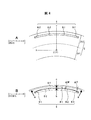
- ⁇ Inner cut 4> B in FIG. 1 is an enlarged view of the inner cut 4 in the IB portion of A in FIG.
- this inner cut 4 it is a through hole portion penetrating the upper and lower surfaces of the gasket 2 with a long side length L and a width W having a constant arc shape in the circumferential direction of the gasket 2.
- Each inner cut 4 has vertical surface portions 6-1 and 6-2 facing each other with a constant width W, inner peripheral surface portions 8-1 facing each other with a long side length L, and outer peripheral surface portions 8-2.
- the height D is the thickness of the gasket 2 before deformation.
- each inner cut 4 may be set at a plurality of locations on the gasket 2. It is preferable that the set position is not biased in order to avoid the influence of the elastic interaction received from the flanges 16-1 and 16-2 and to improve the detection accuracy of the shape change.
- each inner cut 4 is set at four locations on the X-axis and the Y-axis, and the shape change can be detected in a wide range.
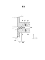
- FIG. 2 shows a notch in the flange fastening portion 12 including the gasket 2.
- the flange fastening portion 12 is an example, and the present disclosure is not limited to the configuration shown in FIG.
- the flange fastening portion 12 includes a flange 16-1 on the pipeline 14-1 side, a flange 16-2 on the pipeline 14-2 side (FIG. 3), a gasket 2, a plurality of bolts 18, and a nut 20.
- the flange 16-1 is integrally formed with the end face of the pipeline 14-1, and similarly, the flange 16-2 is integrally formed with the end face of the pipeline 14-2.
- the flanges 16-1 and 16-2 have a larger diameter than the pipelines 14-1 and 14-2, and a plurality of bolts 18 and nuts 20 are attached at predetermined angular intervals.
- a gasket 2 is installed between the flanges 16-1 and 16-2 inside the bolt 18 and the nut 20.
- the gasket 2 constitutes a sealing member for the flange fastening portion 12. Therefore, by tightening the bolts 18 and nuts 20, the gasket 2 is loaded by the load F applied to the flanges 16-1 and 16-2, and the gaskets 2 are sealed together with the fastening of the pipelines 14-1 and 14-2. ..
- the restraining portion 2-1 of the gasket 2 is sandwiched between the flanges 16-1 and 16-2, and is in contact with the flanges 16-1 and 16-2 to be restrained.
- the unconstrained portion 2-2 protrudes around the restraining portion 2-1 and does not contact the flanges 16-1 and 16-2, that is, it is not constrained by the flanges 16-1 and 16-2.
- the restraining portion 2-1 receives the load F from the flanges 16-1 and 16-2, whereas the non-constraining portion 2-2 constitutes a free end that does not receive the load F. ing.
- each inner cut 4 of the non-restraint portion 2-2 constitutes a portion for detecting a shape change appearing on the gasket 2. Assuming that the load F acts in the Z-axis direction, the strain occurs in the X-axis and Y-axis directions, for example.
- FIG. 3 shows the III-III line cut end face of FIG.
- the restraining portion 2-1 of the gasket 2 is sandwiched and restrained between the gasket seats 22 of the flanges 16-1 and 16-2.
- the unconstrained portion 2-2 protrudes into the gap 24 between the flanges 16-1 and 16-2.
- the non-constrained portion 2-2 is integrated with the restraint portion 2-1 and is supported between the flanges 16-1 and 16-2, and is a free end protruding into the gap 24. That is, the unrestrained portion 2-2 is in a cantilever state.
- Strains and deformations that occur in the restraint portion 2-1 when the load F is received from the flanges 16-1 and 16-2 appear as shape changes in the non-constraint portion 2-2. This shape change can be easily observed from the inner cut 4. That is, the shape change of the gasket 2 that appears in the non-constrained portion 2-2 is distortion or deformation due to being pushed out from between the gasket seats 22, and the restrained portion 2-1 of the gasket 2 is from the flanges 16-1 and 16-2. Represents the load received.
- the inner cut 4 is formed in order to make the strain generated in the unconstrained portion 2-2 manifest as a remarkable shape change and facilitate its observation.
- the unrestrained portion 2-2 spreads by ⁇ Y in the radial direction of the gasket 2 (indicated by the arrow a), and the inner peripheral surface portion 8-1, the outer peripheral surface portion 8-2, and the vertical surface portion 6 -1 and 6-2 also move in the radial direction of the gasket 2.
- the width W of the inner cut 4 is narrowed to the width ⁇ W as the distance between the inner peripheral surface portion 8-1 and the outer peripheral surface portion 8-2 is indicated by arrows b and c.
- the shape change in the XY-axis direction is illustrated, but it goes without saying that the shape change in the Z-axis direction and the thickness direction also appears in the shape of the inner cut 4.
- the strain generated in the restrained portion 2-1 and the non-constrained portion 2-2 by receiving the load F from the flanges 16-1 and 16-2 is manifested as a shape change of the inner cut 4, and its observation is facilitated. Can be done.
- the inner cut 4 is not limited to the form shown in B of FIG. A, B, and C in FIG. 5 show a modification of the inner cut 4.
- the parts corresponding to B in FIG. 1 are designated by the same reference numerals.
- the inner cut 4 is a parallel surface or non-parallel surface composed of linear facing surface portions 9-1 and 9-2 instead of the above-mentioned inner peripheral surface portion 8-1 and outer peripheral surface portion 8-2. It may be formed on parallel surfaces, or as shown in FIG. 5B, it may be formed in a square or fan shape consisting of four surfaces of the facing surface portions 7-1 and 7-2 and the facing surface portions 9-1 and 9-2. good. Further, as shown in C of FIG. 5, by forming the surface portions 9-11 and 9-12 on the facing surface portions 9-1, the widths of the facing surface portions 9-1 and 9-2 are partially different, for example. , Wa, Wb (Wa ⁇ Wb). Even in such a form, the shape change that occurs in the non-constrained portion 2-2 when the load F is received by the restrained portion 2-1 can be easily detected from the inner cut 4.
- a sensor member such as metal or resin may be installed in the space portion of the inner cut 4, and the shape change of the inner cut 4 may be extracted from this sensor member.
- the management process of the gasket 2 is an example of the management method of the present disclosure.
- This management step includes a generation step S1 of the restraint portion 2-1 and the non-constraint portion 2-2, an addition step S2 of the load F, a shape information acquisition step S3, and a presentation step S4 of the shape information and the like.
- S1 to S4 attached to each step exemplify the order of each step, and the terms quoted are only used for convenience.
- Load F addition step S2 In the gasket 2, the load F is applied to the restraint portion 2-1 restrained by the flanges 16-1 and 16-2 by tightening the flanges 16-1 and 16-2. In response to this load F, the gasket 2 causes strain in the restraining portion 2-1 and causes a shape change in the non-constraining portion 2-2.
- Shape information acquisition step S3 Regarding the shape change appearing in the unconstrained portion 2-2, the management server 30 (FIG. 6) receives the detection output of the strain sensor 28 and acquires the shape information of the inner cut 4.
- the management server 30 generates presentation information including shape information and presents it by the information presentation unit 32 (FIG. 6).
- the shape information acquired in the shape information acquisition step S3 may be subjected to Nth derivative (multi-step differentiation) to make the change points of the shape information stand out. If this processing result is reflected in the presentation information in the presentation step S4, the change point of the shape information can be clarified.
- FIG. 6 shows a gasket management system 26 for executing a management process by information processing.
- the configuration shown in FIG. 6 is an example, and the present disclosure is not limited to such a configuration.
- the same parts as those in FIG. 3 are designated by the same reference numerals.
- This gasket management system 26 includes a strain sensor 28, a management server 30, and an information presentation unit 32.
- the strain sensor 28 measures the shape change appearing in the inner cut 4 of the gasket 2 and outputs a detection signal indicating this shape change.
- the strain sensor 28 is an example of a means for detecting a shape change and converting it into an electric signal.
- a laser displacement meter, a camera, or the like may be used as the means for observing the shape change.
- the laser displacement meter shines a laser beam on the inner cut 4, detects a change in the shape of the inner cut 4 with the reflected light, and observes the amount of the change.
- the camera captures the inner cut 4, and the management server 30 detects the strain appearing in the inner cut 4 by the number of pixels, and acquires the shape information according to the strain.
- the management server 30 is composed of a computer having a communication function.
- the management server 30 includes a processor 34, a storage unit 36, an input / output (I / O) unit 38, and a communication unit 40.
- the processor 34 executes an OS (Operating System) and a management program in the storage unit 36, and performs information processing for gasket management.
- the storage unit 36 includes a storage medium for storing the OS and the management program.
- the gasket management database (DB) 42 (FIG. 7) is stored in the storage unit 36.
- the communication unit 40 inputs and presents information in cooperation with a management terminal (not shown).
- the management terminal is also used for acquiring shape information and writing and reading the gasket management DB 42.
- the information presenting unit 32 presents shape information including a load and determination information under the control of the management server 30.
- ⁇ Information processing of management server 30> For information processing of the management server 30, a) Processing for capturing the detection output of the strain sensor 28 b) Acquisition of shape information of the inner cut 4 c) Generation of presentation information including shape information d) Processing such as presentation of estimation information by the information presentation unit 32 is included.
- FIG. 7 shows an example of the gasket management DB 42.
- This gasket management DB 42 is used for processing such as estimating a load from shape information.
- the gasket management file 44 is stored in the gasket management DB 42.
- the gasket management file 44 includes a gasket information unit 46, an inner cut information unit 47, a time information unit 48, a load information unit 50, a strain sensor information unit 52, a detection information unit 54, a judgment information unit 56, and a history information unit 58. It is set.
- the gasket information unit 46 stores specification information for specifying the gasket 2.
- the inner cut information unit 47 stores shape information such as the shape representing the inner cuts 4-1, 4-2, 4-3, and 4-4, and the arrangement position and size thereof.
- Time information such as the measurement date and time is stored in the time information unit 48.
- the load information unit 50 stores load information representing the load F applied between the flanges 16-1 and 16-2 by tightening the bolt 18.
- the determination information unit 56 stores estimated load information representing the load estimated from the shape information by the information processing of the management server 30.
- the history information unit 58 stores history information such as shape information acquisition and estimation processing.
- the restraining portion 2-1 receives the load F from the flanges 16-1 and 16-2, and the strain generated in the restraining portion 2-1 is applied to the non-constraining portion 2-2. It can be visualized as a shape change of the inner cut 4, and the shape change corresponding to the load F can be easily observed from the inner cut 4.
- the shape information of the inner cut 4 can be acquired from the inner cut 4 by the detection output of each strain sensor 28, and the load received by the gasket 2 from the flanges 16-1 and 16-2 can be estimated from the shape change.
- the strain of the gasket 2 can be observed by the shape change of the inner cut 4, and the load received by the gasket 2 is estimated from the shape change without being affected by the tightening torque and the axial force of the bolt 18, and the gasket 2 is used.
- the tightening state of can be determined.
- the management method of the gasket 2 according to the second embodiment further includes the estimation step S5 based on the minimum point information in the management method of the first embodiment.
- the shape information can include a minimum point as peculiar information of the load.
- the load F that is, the surface pressure can be estimated from the shape change of the inner cut 4 received by the gasket 2, and the monitoring or adjustment of the tightened state with respect to the gasket 2 can be facilitated.
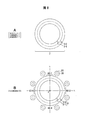
- FIG. 8A shows the gasket 2 according to the comparative example.
- the restrained portion 2-1 and the non-constrained portion 2-2 are set concentrically with the same width or substantially the same width.
- shape observation units 60-1, 60-2, 60-3, 60-4 are set at positions corresponding to the inner cut 4 of the embodiment. ing.
- the shape observation units 60-1, 60-2, 60-3, and 60-4 are arranged in the unconstrained unit 2-2 at an angular interval of 90 degrees at a center angle.
- the arrangement positions of the shape observation units 60-1, 60-2, 60-3, and 60-4 are set to positions that do not overlap with the arrangement positions of the bolts 18.
- Table 1 shows the shape of the inner cut 4 of the gasket 2 and the measurement results thereof according to the embodiment.
- Example 1 the shape of the inner cut 4 in Example 1, Example 2, Example 3, and Example 4, the distance between the long sides at the completion of tightening, the minimum point load, and the dimensional information and load information of the comparative example are shown. Shows.
- FIG. 9 shows the relationship between the shape change (change in the distance between long sides) and the load according to Example 1, Example 2, Example 3, and Example 4.
- n1 shows the change in Example 1
- n2 shows the change in Example 2
- n3 shows the change in Example 3
- n4 shows the change in Example 4. Comparing these, it can be seen that the shape changes of n1 and n2 are remarkable, and it is easy to identify the load applied to the gasket 2 by observing the shape changes.
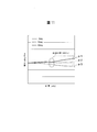
- FIG. 10 shows the relationship between the minimum point information appearing in the shape change and the load by taking the load on the horizontal axis and the strain on the vertical axis.
- o1 shows a shape change in the 0 (deg) direction
- o2 shows a shape change in the 45 (deg) direction
- o3 shows a shape change in the 90 (deg) direction.
- the minimum point is generated in the shape change in Examples 1 and 2.
- FIG. 11 shows the relationship between the inflection point appearing in the shape change and the load when the long side length L of the inner cut 4 is short.
- p1 shows a shape change in the 0 (deg) direction
- p2 shows a shape change in the 45 (deg) direction
- p3 shows a shape change in the 90 (deg) direction.
- the relationship between the shape change and the load can be specified by measuring the shape change of the inner cut 4.
- the shape change appearing in the inner cut 4 of the non-restraint portion 2-2 can be measured, and the shape information representing the load can be obtained from the gasket 2. .. Therefore, the load can be estimated from the shape change of the gasket 2 due to the load F applied to the flanges 16-1 and 16-2 without being affected by the bolt 18 and the flanges 16-1 and 16-2.
- the gasket 2 can also handle various diameters and thicknesses.
- FIG. 12 shows a configuration example of the gasket 70 according to the fifth embodiment.
- This gasket 70 is, for example, a laminated body in which a plurality of members having different diameters are coaxially arranged, and is a spiral-wound gasket provided with an outer ring 701, a gasket main body 702, and an inner ring 703.
- the gasket 70 is, for example, a restraint portion 2-1 in which only the inner ring 703, a part or all of the inner ring 703 and the gasket body 702, and a part of the outer ring 701 come into contact with the gasket seat 22 (FIG. 3) and receive a load F. .. That is, in the gasket 70, a part or all of the outer ring 701 becomes an unconstrained portion 2-2.
- the gasket body 702 of the gasket 70 is deformed according to the load F from the flanges 16-1 and 16-2, and the outer ring 701 is distorted due to this deformation.
- the gasket 70 has one or a plurality of inner cuts 4 formed on a part of the outer ring 701.
- the inner cut 4 is, for example, 5 [mm] as a predetermined distance t from the outer edge portion of the outer ring 701. It is formed at the position of.
- the shape of the inner cut 4 is measured and the surface pressure state of the gasket 70 is managed.
- the strain sensor 28 of the gasket management system 26 may be used.
- the gasket management system 26 calculates the shape of the inner cut 4 based on the measured shape change Qa.
- the management process of the tightened state of the gasket 70 the same process as that of the above embodiment may be performed.
- the outer ring 701 and the inner ring 703 are made of a metal material such as stainless steel, carbon steel, or titanium, and are formed in a ring having a predetermined thickness or a shape close to the ring.
- a thin plate-shaped member made of a metal material and a laminated body of a cushioning material (filler) such as graphite or fluororesin are spirally wound between the inner wall surface of the outer ring 701 and the outer wall surface of the inner ring 703. It is composed by winding around.
- the laminate constituting the gasket main body 702 is formed, for example, in a cross section having a “V” shape or a waveform close to the “V” shape.
- the end faces are fixed to the outer ring 701 and the inner ring 703 by spot welding.
- the outer ring 701 has an inner cut 4a opened with a predetermined width before the load F from the flanges 16-1 and 16-2 is applied to the gasket main body 702. Then, when the load F acts through the gasket body 702, the outer ring 701 is formed into an inner cut 4b in which a part or all of the opening portion is deformed and closed, as shown in FIG. 15, for example, C.
- FIG. 13 shows the measured values of the circumferential shape change Qa (FIG. 12) appearing on the outer edge of the outer ring 701 measured by the strain sensor 28, with the load [kN] on the horizontal axis and the strain (shape change) on the vertical axis. ing.
- the shape change of the inner cut 4 is measured from the shape change Qa that occurs in the outer ring 801.
- a change representing the load F can be obtained from the gasket 8. Therefore, the load F applied to the flanges 16-1 and 16-2 can be estimated from the shape change of the gasket 70 without being affected by the bolts 18 and the flanges 16-1 and 16-2.
- a management system that manages flange fastenings with gaskets between flanges.
- a restraining portion that is restrained between the flanges and receives a load
- a non-constraining portion that is not restrained between the flanges
- a through hole portion provided in the non-constraining portion
- a gasket that receives the load and causes a change in the through hole
- a measuring instrument that measures changes in the through-hole portion in contact with or without contact with the gasket.
- a management server that acquires measurement information from the measuring instrument and generates management information including the tightening force between the flanges.
- An information presenting unit that presents the management information in relation to the gasket or the flange fastening portion, and A management system.
- a recording medium on which a program to be realized by a computer is recorded A function to acquire shape information including changes that occur in the through hole in the non-constrained portion of the gasket due to being restrained between the flanges and receiving a load from the flanges. A function to generate management information including the tightening force between the flanges based on the shape information, and The function of presenting the management information and A recording medium on which a program for realizing the above-mentioned computer is recorded.
- the initial fastening at the flange fastening portion 12 receives a load from between the flanges and observes the shape change generated in the gasket 2, but the initial fastening of the flange fastening is performed. Not limited.
- the shape of the inner cut 4 described above is an example, and even if it is an arc shape having no vertical surface portion 6, or a polygonal shape or a rectangular through hole portion having a linear parallel surface portion or a non-parallel surface portion. good.
- the load F applied to the gasket 2 sandwiched between the flanges 16-1 and 16-2 and the shape change of the gasket 2 are described.
- the load F applied to the gasket 2 is equivalent to the surface pressure received by the gasket 2 from the flanges 16-1 and 16-2, and there is no qualitative difference between the two. That is, the surface pressure of the gasket 2 can be estimated from the relationship between the load F applied to the gasket 2 and the shape change appearing in the inner cut 4.
- the management server 30 may generate presentation information by processing the acquired shape information by multi-step differentiation or the like, and the information presentation unit may be used.
- a display unit that clearly indicates the change point may be presented in 32 (FIG. 6).
- the shape change of the inner cut of the gasket can be observed for the gasket for fastening between the flanges, so that the gasket is not affected by the tightening state of the bolt or the flange. It can be used for management information such as gasket tightening management and replacement.
Landscapes
- Engineering & Computer Science (AREA)
- General Engineering & Computer Science (AREA)
- Mechanical Engineering (AREA)
- Physics & Mathematics (AREA)
- General Physics & Mathematics (AREA)
- Gasket Seals (AREA)
Priority Applications (3)
| Application Number | Priority Date | Filing Date | Title |
|---|---|---|---|
| KR1020227043629A KR20230036065A (ko) | 2020-07-08 | 2021-07-06 | 개스킷, 그 관리의 방법, 시스템 및 프로그램 |
| JP2022535334A JP7661336B2 (ja) | 2020-07-08 | 2021-07-06 | ガスケットの管理の方法、システムおよびプログラム |
| CN202180048466.7A CN115777046A (zh) | 2020-07-08 | 2021-07-06 | 衬垫及其管理方法、系统以及程序 |
Applications Claiming Priority (2)
| Application Number | Priority Date | Filing Date | Title |
|---|---|---|---|
| JP2020-117732 | 2020-07-08 | ||
| JP2020117732 | 2020-07-08 |
Publications (1)
| Publication Number | Publication Date |
|---|---|
| WO2022009866A1 true WO2022009866A1 (ja) | 2022-01-13 |
Family
ID=79553144
Family Applications (1)
| Application Number | Title | Priority Date | Filing Date |
|---|---|---|---|
| PCT/JP2021/025408 Ceased WO2022009866A1 (ja) | 2020-07-08 | 2021-07-06 | ガスケット、その管理の方法、システムおよびプログラム |
Country Status (5)
| Country | Link |
|---|---|
| JP (1) | JP7661336B2 (https=) |
| KR (1) | KR20230036065A (https=) |
| CN (1) | CN115777046A (https=) |
| TW (1) | TWI901719B (https=) |
| WO (1) | WO2022009866A1 (https=) |
Cited By (2)
| Publication number | Priority date | Publication date | Assignee | Title |
|---|---|---|---|---|
| JP2022134703A (ja) * | 2021-03-04 | 2022-09-15 | 株式会社バルカー | ガスケットおよびその製造方法 |
| JP2022134702A (ja) * | 2021-03-04 | 2022-09-15 | 株式会社バルカー | ガスケットセンサーおよびその製造方法 |
Citations (3)
| Publication number | Priority date | Publication date | Assignee | Title |
|---|---|---|---|---|
| JPH0583576U (ja) * | 1992-04-13 | 1993-11-12 | 株式会社川本製作所 | 管フランジ用ガスケット |
| JPH09329281A (ja) * | 1996-06-07 | 1997-12-22 | Toshiba Corp | フランジ締結監視装置 |
| JP2013040647A (ja) * | 2011-08-15 | 2013-02-28 | Hitachi-Ge Nuclear Energy Ltd | フランジのガスケット締代測定方法 |
Family Cites Families (7)
| Publication number | Priority date | Publication date | Assignee | Title |
|---|---|---|---|---|
| JP4699935B2 (ja) | 2006-04-26 | 2011-06-15 | 株式会社日立エンジニアリング・アンド・サービス | フランジ締結監視装置 |
| JP2007327576A (ja) * | 2006-06-08 | 2007-12-20 | Nippon Pillar Packing Co Ltd | 金属ガスケット及びその製造方法 |
| EP2801739A3 (en) * | 2013-05-10 | 2015-04-29 | FOCE Technology International B.V. | Gasket pressure sensor |
| JP2014225219A (ja) | 2013-11-07 | 2014-12-04 | ニチアス株式会社 | ガスケット締付計算システム、ガスケット締付計算システムの制御方法、及び、プログラム |
| JP2015141345A (ja) | 2014-01-29 | 2015-08-03 | 日本バルカー工業株式会社 | フランジ締付け実習システム |
| CN109416890B9 (zh) * | 2016-07-07 | 2021-05-11 | 株式会社华尔卡 | 密封施工的实习装置和实习方法 |
| CN210108582U (zh) * | 2019-05-13 | 2020-02-21 | 湖南申亿五金标准件有限公司 | 一种可检测预紧力的垫圈 |
-
2021
- 2021-07-06 KR KR1020227043629A patent/KR20230036065A/ko not_active Ceased
- 2021-07-06 TW TW110124799A patent/TWI901719B/zh active
- 2021-07-06 CN CN202180048466.7A patent/CN115777046A/zh active Pending
- 2021-07-06 WO PCT/JP2021/025408 patent/WO2022009866A1/ja not_active Ceased
- 2021-07-06 JP JP2022535334A patent/JP7661336B2/ja active Active
Patent Citations (3)
| Publication number | Priority date | Publication date | Assignee | Title |
|---|---|---|---|---|
| JPH0583576U (ja) * | 1992-04-13 | 1993-11-12 | 株式会社川本製作所 | 管フランジ用ガスケット |
| JPH09329281A (ja) * | 1996-06-07 | 1997-12-22 | Toshiba Corp | フランジ締結監視装置 |
| JP2013040647A (ja) * | 2011-08-15 | 2013-02-28 | Hitachi-Ge Nuclear Energy Ltd | フランジのガスケット締代測定方法 |
Cited By (4)
| Publication number | Priority date | Publication date | Assignee | Title |
|---|---|---|---|---|
| JP2022134703A (ja) * | 2021-03-04 | 2022-09-15 | 株式会社バルカー | ガスケットおよびその製造方法 |
| JP2022134702A (ja) * | 2021-03-04 | 2022-09-15 | 株式会社バルカー | ガスケットセンサーおよびその製造方法 |
| JP7581087B2 (ja) | 2021-03-04 | 2024-11-12 | 株式会社バルカー | ガスケットおよびその製造方法 |
| JP7581086B2 (ja) | 2021-03-04 | 2024-11-12 | 株式会社バルカー | ガスケットセンサーおよびその製造方法 |
Also Published As
| Publication number | Publication date |
|---|---|
| CN115777046A (zh) | 2023-03-10 |
| JPWO2022009866A1 (https=) | 2022-01-13 |
| TWI901719B (zh) | 2025-10-21 |
| TW202206724A (zh) | 2022-02-16 |
| KR20230036065A (ko) | 2023-03-14 |
| JP7661336B2 (ja) | 2025-04-14 |
Similar Documents
| Publication | Publication Date | Title |
|---|---|---|
| JP7257055B2 (ja) | 溶接構造物の統一疲労寿命評価方法 | |
| WO2022009866A1 (ja) | ガスケット、その管理の方法、システムおよびプログラム | |
| Merklein et al. | A method for the layer compression test considering the anisotropic material behavior | |
| KR101629538B1 (ko) | 원자력 발전소의 증기 발생기 튜브의 현재 상태를 비파괴적으로 평가하는 방법 | |
| JP7661335B2 (ja) | ガスケットの管理方法、システムおよびプログラム | |
| US11898986B2 (en) | Systems and methods for steam generator tube analysis for detection of tube degradation | |
| Kang et al. | Constitutive behavior of AA5754 sheet materials at large strains | |
| TWI826551B (zh) | 密封施工的判定系統、判定程式、判定方法及學習系統 | |
| CN102288352A (zh) | 一种测定螺栓扭矩系数的方法和装置 | |
| US7159470B2 (en) | Systems and methods of measuring residual stress in metallic materials | |
| JPWO2019189293A1 (ja) | フランジ間計測装置、プログラムおよび方法 | |
| WO2022009865A1 (ja) | ガスケット、その管理の方法、システムおよびプログラム | |
| Jang et al. | J and CTOD-based tensile strain capacity prediction for pipelines with a surface crack in girth weld | |
| Dharmadhikari et al. | Energy dissipation metrics for fatigue damage detection in the short crack regime for aluminum alloys | |
| Kainat et al. | Measurement and characterization of the initial geometric imperfections in high strength U-ing, O-ing and expanding manufactured steel pipes | |
| JP5036411B2 (ja) | 雄ネジ部品の締付方法及びトルクレンチ | |
| Lahiri et al. | Infrared thermography-based studies on hydrotesting of stainless steel pressure vessels | |
| Shuvaev et al. | Quality Assurance of Assembling of GTE Threaded Joints by Ultrasonic Treatment upon the Required Strength Criterion | |
| Deleau et al. | Towards a better assessment of Clip-connector fatigue thanks to an improved design methodology and the use of acoustic emission | |
| WO2024247906A1 (ja) | フランジ締結管理システムおよび中継機 | |
| WO2024247907A1 (ja) | 締結サポートのシステム、方法、プログラム、ガスケットおよびその製造方法 | |
| JP4865741B2 (ja) | 鋼管の曲げ部の損傷評価方法 | |
| ROMAN et al. | Influence of bolts bending on the strength of flanges joints of pressure vessels | |
| Brown et al. | An update on selecting the optimum bolt assembly stress for piping flanges | |
| Butt et al. | Characterization of Defect Distribution in an Additively Manufactured AlSi10Mg as a Function of Processing Parameters and Correlations with Extreme Value Statistics |
Legal Events
| Date | Code | Title | Description |
|---|---|---|---|
| 121 | Ep: the epo has been informed by wipo that ep was designated in this application |
Ref document number: 21836787 Country of ref document: EP Kind code of ref document: A1 |
|
| ENP | Entry into the national phase |
Ref document number: 2022535334 Country of ref document: JP Kind code of ref document: A |
|
| NENP | Non-entry into the national phase |
Ref country code: DE |
|
| 122 | Ep: pct application non-entry in european phase |
Ref document number: 21836787 Country of ref document: EP Kind code of ref document: A1 |