WO2022009808A1 - 産業用ロボット - Google Patents
産業用ロボット Download PDFInfo
- Publication number
- WO2022009808A1 WO2022009808A1 PCT/JP2021/025203 JP2021025203W WO2022009808A1 WO 2022009808 A1 WO2022009808 A1 WO 2022009808A1 JP 2021025203 W JP2021025203 W JP 2021025203W WO 2022009808 A1 WO2022009808 A1 WO 2022009808A1
- Authority
- WO
- WIPO (PCT)
- Prior art keywords
- arm portion
- arm
- wall portion
- motor
- industrial robot
- Prior art date
- Legal status (The legal status is an assumption and is not a legal conclusion. Google has not performed a legal analysis and makes no representation as to the accuracy of the status listed.)
- Ceased
Links
Images



Classifications
-
- B—PERFORMING OPERATIONS; TRANSPORTING
- B25—HAND TOOLS; PORTABLE POWER-DRIVEN TOOLS; MANIPULATORS
- B25J—MANIPULATORS; CHAMBERS PROVIDED WITH MANIPULATION DEVICES
- B25J9/00—Program-controlled manipulators
- B25J9/06—Program-controlled manipulators characterised by multi-articulated arms
Definitions
- the present invention relates to a horizontal articulated industrial robot.
- a horizontal articulated industrial robot that conveys a semiconductor wafer is known (see, for example, Patent Document 1).
- the industrial robot described in Patent Document 1 two hands on which a semiconductor wafer is mounted, an arm in which the two hands are rotatably connected to the tip side, and a base end side of the arm are rotatable. It has a main body to be connected.
- the arm consists of a first arm portion whose base end side is rotatably connected to the main body portion, a second arm portion whose base end side is rotatably connected to the tip end side of the first arm portion, and a second arm portion. It is composed of a third arm portion whose base end side is rotatably connected to the tip end side of the above.
- Two hands are rotatably connected to the tip end side of the third arm portion.
- the industrial robot described in Patent Document 1 is provided with a third arm portion rotating mechanism that rotates the third arm portion with respect to the second arm portion.
- the third arm portion rotating mechanism includes a motor arranged inside the second arm portion formed in a hollow shape.
- the motor includes a motor main body and an output shaft that projects horizontally from the motor main body. The axial direction of the output shaft of the motor coincides with the longitudinal direction of the second arm portion orthogonal to the vertical direction.
- the second arm portion includes an upper wall portion constituting the upper surface of the second arm portion, a lower wall portion constituting the lower surface of the second arm portion, and an arm portion in the vertical direction. It is provided with two side wall portions constituting the side surface of the second arm portion in the lateral direction of the arm portion orthogonal to the longitudinal direction of the arm portion.
- a recess is formed on the lower surface of the upper wall portion to prevent interference between the upper wall portion and the motor body portion, and on the upper surface of the lower wall portion, in order to prevent interference between the lower wall portion and the motor body portion. The recess is formed.
- the second arm portion is made thin. It is possible to make it smaller (that is, to make it smaller in the vertical direction).
- the subject of the present invention is that even if the motor is arranged inside the hollow arm portion that constitutes a part of the arm so that the longitudinal direction of the arm portion and the axial direction of the output shaft coincide with each other, the arm It is an object of the present invention to provide an industrial robot capable of reducing the thickness of the portion and stabilizing the operation of the arm portion.
- the industrial robot of the present invention is a horizontal articulated industrial robot, in which a hollow arm portion constituting a part of the arm, a motor main body portion, and a motor main body portion are oriented in the horizontal direction. It is equipped with a motor that has an output shaft protruding from the arm and is arranged inside the arm, and the axial direction of the output shaft coincides with the longitudinal direction of the arm that is orthogonal to the vertical direction.
- the motor is provided at the center position of the arm portion in the lateral direction of the arm portion, and is recessed upward toward the lower surface of the upper wall portion at least at the place where the motor main body portion is arranged.
- An upper concave portion is formed, and a lower concave portion that is recessed toward the lower side is formed on the upper surface of the lower wall portion, and an upper concave portion is formed in the longitudinal direction of the arm portion.
- the vertical thickness of both ends in the lateral direction of the portion is thicker than the vertical thickness of the portion of the upper wall where the upper concave portion is formed, and the lower concave portion is formed in the longitudinal direction of the arm portion.
- the vertical thickness of both ends of the arm portion in the lateral direction of the lower wall portion is thicker than the vertical thickness of the portion of the lower wall portion where the lower concave portion is formed. It is characterized by being.
- an upper concave portion that is recessed toward the upper side is formed on the lower surface of the upper wall portion at least at a position where the motor main body portion is arranged, and the upper surface portion of the lower wall portion is formed on the lower side.
- a lower recess is formed that is recessed toward it. Therefore, in the present invention, even if the motor is arranged inside the hollow arm portion so that the longitudinal direction of the arm portion and the axial direction of the output shaft coincide with each other, the arm portion can be made thinner. Become.
- the motor is arranged at the center position of the arm portion in the lateral direction of the arm portion.
- the vertical thickness of both ends of the upper wall portion in the lateral direction is the upper concave portion of the upper wall portion.
- the vertical direction of both ends of the lower wall portion in the lateral direction of the arm portion is thicker than the vertical thickness of the portion of the lower wall where the lower recess is formed.
- the upper concave portion and the lower concave portion are formed in the longitudinal direction of the arm portion. , It is possible to secure the strength of the boundary portion between the upper wall portion and the two side wall portions and the strength of the boundary portion between the lower wall portion and the two side wall portions, and in the lateral direction of the arm portion. It becomes possible to maintain the balance of the strength of the arm portion in the above.
- the arm portion in order to make the arm portion thinner, even if the upper concave portion is formed on the upper wall portion and the lower concave portion is formed on the lower wall portion, the arm when the industrial robot operates is formed. It becomes possible to suppress the deformation of the portion, and as a result, it becomes possible to stabilize the operation of the arm portion. That is, in the present invention, even if the motor is arranged inside the hollow arm portion that constitutes a part of the arm so that the longitudinal direction of the arm portion and the axial direction of the output shaft coincide with each other, the arm portion is provided. It becomes possible to reduce the thickness and stabilize the operation of the arm portion.
- the vertical thicknesses of both ends of the upper wall portion in the lateral direction of the arm portion are equal to each other, and the thickness of the arm portion is equal to each other.
- the thicknesses of the lower wall portion in the vertical direction of both ends of the arm portion in the lateral direction are equal to each other.
- the thicknesses of the two side wall portions in the lateral direction of the arm portion become equal to each other. It is preferable to have. With this configuration, it is possible to improve the balance of the strength of the arm portion in the lateral direction of the arm portion at the portion where the upper concave portion and the lower concave portion are formed in the longitudinal direction of the arm portion. Therefore, in order to make the arm portion thinner, even if the upper concave portion is formed on the upper wall portion and the lower concave portion is formed on the lower wall portion, the deformation of the arm portion when the industrial robot operates is deformed. It becomes possible to suppress it more, and as a result, it becomes possible to make the operation of the arm portion more stable.
- the motor is arranged at an intermediate position of the arm portion in the longitudinal direction of the arm portion.
- the motor is arranged inside the hollow arm portion constituting a part of the arm so that the longitudinal direction of the arm portion and the axial direction of the output shaft coincide with each other. Even so, the arm portion can be made thinner and the operation of the arm portion can be stabilized.
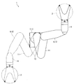
- FIG. 1 It is a side view of the industrial robot which concerns on embodiment of this invention. It is a top view of the industrial robot shown in FIG. It is a figure for demonstrating the internal structure of the arm part shown in FIG. It is a figure for demonstrating the structure of the E part of FIG. It is a figure which shows the internal structure of the arm part from the FF direction of FIG.
- FIG. 1 is a side view of the industrial robot 1 according to the embodiment of the present invention.
- FIG. 2 is a plan view of the industrial robot 1 shown in FIG.
- FIG. 3 is a diagram for explaining the internal configuration of the arm portion 11 shown in FIG.
- the industrial robot 1 of this embodiment (hereinafter referred to as "robot 1") is a horizontal articulated robot for transporting a semiconductor wafer 2 which is a transport target, and is used by being incorporated in a semiconductor manufacturing system. Will be done.
- the robot 1 includes two hands 4 and 5 on which the semiconductor wafer 2 is mounted, an arm 6 in which the hands 4 and 5 are rotatably connected to the tip side and operates in the horizontal direction, and a base end of the arm 6. It includes a main body 7 whose sides are rotatably connected.
- the arm 6 is composed of three arm portions 10 to 12.
- the base end portion of the arm portion 10 is rotatably connected to the main body portion 7.
- the base end portion of the arm portion 11 is rotatably connected to the tip end portion of the arm portion 10.
- the base end portion of the arm portion 12 is rotatably connected to the tip end portion of the arm portion 11.
- the arm portions 10 to 12 rotate with the vertical direction as the axial direction of rotation.
- the arm portions 10 to 12 are formed in a hollow shape.
- the main body portion 7, the arm portion 10, the arm portion 11, and the arm portion 12 are arranged in this order from the lower side in the vertical direction.
- the hands 4 and 5 are formed so that the shape when viewed from the vertical direction is substantially a Y shape.
- the base ends of the hands 4 and 5 are rotatably connected to the tip of the arm portion 12.
- the hands 4 and 5 rotate with the vertical direction as the axial direction of rotation.
- the base end portion of the hand 4 and the base end portion of the hand 5 overlap each other in the vertical direction.
- the hand 4 is arranged on the upper side and the hand 5 is arranged on the lower side.
- the hands 4 and 5 are arranged above the arm portion 12.
- the main body 7 includes a housing 13 and a columnar member (not shown) to which the base end of the arm 10 is rotatably connected.
- the base end portion of the arm portion 10 is rotatably connected to the upper end portion of the columnar member.
- An arm elevating mechanism (not shown) for elevating and lowering a columnar member is housed inside the housing 13. The arm elevating mechanism raises and lowers the arm 6 and the columnar member between the position where the columnar member is housed in the housing 13 and the position where the columnar member projects upward from the housing 13.
- the robot 1 has an arm drive mechanism that rotates the arm portions 10 and 11 to expand and contract a part of the arm 6 including the arm portion 10 and the arm portion 11, and rotates the arm portion 12 with respect to the arm portion 11.
- the arm drive mechanism includes a motor (not shown) arranged inside the housing 13, a speed reducer for decelerating the power of the motor and transmitting it to the arm portion 10 (not shown), and decelerating the power of the motor.
- a speed reducer 17 or the like for transmitting to the arm portion 11 is provided.
- the speed reducer 17 constitutes a part of a joint portion connecting the arm portion 10 and the arm portion 11 (see FIG. 3).
- the speed reducer 17 is, for example, a hollow hollow wave gear device (harmonic drive (registered trademark)) having a through hole formed in the center in the radial direction.
- the hand drive mechanism is arranged inside the arm portion 12.
- the hand drive mechanism includes a motor and a speed reducer for decelerating the power of the motor and transmitting it to the hands 4 and 5.
- the arm portion rotating mechanism 15 includes a motor 20 and a speed reducer 21 for decelerating the power of the motor 20 and transmitting the power to the arm portion 12.
- a specific configuration of the arm portion 11 and the arm portion rotating mechanism 15 will be described.
- FIG. 4 is a diagram for explaining the configuration of the E portion of FIG.
- FIG. 5 is a diagram showing the internal configuration of the arm portion 11 from the FF direction of FIG.
- the arm portion 11 is formed in a box shape having an elongated oval shape when viewed from the vertical direction. Further, most of the arm portion 11 excluding the tip end portion of the arm portion 11 and the rear end portion of the arm portion 11 is formed in a flat square cylinder having a thin vertical thickness.
- the longitudinal direction (X direction in FIG. 3 and the like) of the arm portion 11 having an oval shape among the directions orthogonal to the vertical direction is referred to as the "front-back direction", and the vertical direction and the front-back direction are used.
- the lateral direction (Y direction in FIG. 5 and the like) of the orthogonal arm portions 11 is defined as the "left-right direction". Further, in the following description, the X1 direction side of FIG.
- the front side (X1 direction side) is the tip end side of the arm portion 11
- the rear side (X2 direction side) is the base end side of the arm portion 11.
- the arm portion rotating mechanism 15 includes a motor 20 and a speed reducer 21.
- the motor 20 includes a motor main body 24 having a stator and the like, and an output shaft 25 protruding from the motor main body 24.
- the motor 20 is arranged inside the arm portion 11. Further, the motor 20 is fixed inside the arm portion 11. Specifically, the motor 20 is fixed to the motor fixing member 26 fixed inside the arm portion 11. That is, the motor 20 is fixed to the inside of the arm portion 11 via the motor fixing member 26. In FIG. 5, the motor fixing member 26 is not shown.
- the output shaft 25 protrudes horizontally from the motor main body 24. Specifically, the output shaft 25 projects forward from the motor main body portion 24, and the axial direction of the output shaft 25 coincides with the front-rear direction (that is, the longitudinal direction of the arm portion 11). As shown in FIG. 5, the motor 20 is arranged at the center position of the arm portion 11 in the left-right direction (the lateral direction of the arm portion 11). In this embodiment, the center in the left-right direction of the motor 20 and the center in the left-right direction of the arm portion 11 are arranged at exactly the same positions in the left-right direction.
- the arm portion 11 in the left-right direction is used. It is assumed that the motor 20 is arranged at the center position of the above.
- the motor 20 is arranged at an intermediate position of the arm portion 11 in the front-rear direction (longitudinal direction of the arm portion 11). Specifically, the motor 20 is arranged at a substantially center position of the arm portion 11 in the front-rear direction. More specifically, the front end portion of the motor main body portion 24 and the center in the front-rear direction of the arm portion 11 are arranged at the same position in the front-rear direction, and the center in the front-rear direction of the motor main body portion 24 is the center of the arm portion 11. It is located behind the center in the front-back direction.
- the speed reducer 21 constitutes a part of a joint portion connecting the arm portion 11 and the arm portion 12.
- the speed reducer 21 is, for example, a hollow hollow wave gear device (harmonic drive (registered trademark)) having a through hole formed in the center in the radial direction.
- a bevel gear 27 is fixed to the input shaft of the speed reducer 21.
- the bevel gear 27 meshes with the bevel gear 28 attached to the output shaft 25 via the coupling and the rotating shaft.
- the power of the motor 20 is transmitted to the speed reducer 21 via the bevel gears 27, 28 and the like.
- the arm portion 11 is formed in a box shape having an elongated oval shape when viewed from the vertical direction. Further, most of the arm portion 11 excluding the tip end portion of the arm portion 11 and the rear end portion of the arm portion 11 is formed in a flat square cylinder having a thin vertical thickness. Further, the arm portion 11 has a symmetrical shape in the left-right direction.
- the arm portion 11 is an upper cover that closes a part of the arm portion main body 30 having an opening formed on the upper surface and an opening formed on a part of the lower surface, and a part of the opening formed on the upper surface of the arm portion main body 30. 31 and a lower cover 32 that closes a part of the opening formed on the lower surface of the arm portion main body 30 are provided.
- the openings formed on the lower surface of the arm portion main body 30 are formed at two locations, the front end portion and the rear end portion of the arm portion main body 30.
- the portion between the opening of the front end portion of the lower surface of the arm portion main body 30 and the opening of the rear end portion of the lower surface portion of the arm portion main body 30 is a flat plate-shaped bottom surface portion 30a constituting the lower surface portion of the arm portion main body 30. It has become.
- the bottom surface portion 30a is arranged so that the thickness direction and the vertical direction of the bottom surface portion 30a coincide with each other.
- the arm portion main body 30 includes two flat plate-shaped side surface portions 30b forming side surfaces of the arm portion main body 30 in the left-right direction.
- the side surface portion 30b is arranged so that the thickness direction and the left-right direction of the side surface portion 30b coincide with each other.
- the upper cover 31 is formed in a thin plate shape.
- the upper cover 31 is fixed to the arm portion main body 30.
- the upper cover 31 is arranged so that the thickness direction and the vertical direction of the upper cover 31 coincide with each other.
- the front end portion of the opening formed on the upper surface of the arm portion main body 30 is closed by the speed reducer 21.
- the upper cover 31 closes the portion of the opening formed on the upper surface of the arm portion main body 30 except for the portion blocked by the speed reducer 21.
- the lower cover 32 is formed in a substantially thin plate shape.
- the lower cover 32 is fixed to the arm portion main body 30.
- the lower cover 32 is arranged so that the thickness direction and the vertical direction of the lower cover 32 coincide with each other.
- the lower cover 32 closes the opening formed in the front end portion of the arm portion main body 30.
- the opening formed at the rear end of the arm body 30 is closed by the speed reducer 17.
- the upper cover 31 is the upper wall portion 11a constituting the upper surface of the arm portion 11. Further, in the present embodiment, the bottom surface portion 30a of the arm portion main body 30 and the lower cover 32 form a lower wall portion 11b forming the lower surface of the arm portion 11. Further, in the present embodiment, the side surface portion 30b of the arm portion main body 30 is two side wall portions 11c constituting the side surface of the arm portion 11 in the left-right direction.
- an upper concave portion 31a that is recessed toward the upper side is formed on the lower surface of the upper cover 31, and is formed on the upper surface of the bottom surface portion 30a on the lower side.
- a lower recess 30c that is recessed toward the surface is formed. That is, at least in a place where the motor main body portion 24 is arranged, an upper recess 31a that is recessed upward is formed on the lower surface of the upper wall portion 11a, and is recessed downward on the upper surface of the lower wall portion 11b.
- the lower recess 30c is formed.
- the upper concave portion 31a is formed to prevent interference between the upper wall portion 11a and the motor main body portion 24, and the lower concave portion 30c is formed to prevent interference between the lower wall portion 11b and the motor main body portion 24. ing.
- the upper recess 31a and the lower recess 30c are rectangular recesses. When viewed from the vertical direction, the four sides forming the outer shape of the upper concave portion 31a are parallel to the front-rear direction or the left-right direction. Similarly, when viewed from the vertical direction, the four sides forming the outer shape of the lower concave portion 30c are parallel to the front-rear direction or the left-right direction. In the left-right direction, the center of the upper recess 31a in the left-right direction coincides with the center of the arm portion 11 in the left-right direction. Further, in the left-right direction, the center of the lower recess 30c in the left-right direction coincides with the center of the arm portion 11 in the left-right direction.
- the width of the upper recess 31a in the left-right direction and the width of the lower recess 30c in the left-right direction are wider than the width of the motor main body portion 24 in the left-right direction. Further, the width of the upper recess 31a in the left-right direction and the width of the lower recess 30c in the left-right direction are narrower than the width of the upper cover 31 in the left-right direction and the distance between the two side wall portions 11c in the left-right direction. .. The width of the lower recess 30c in the left-right direction is wider than the width of the upper recess 31a in the left-right direction.
- the width of the upper recess 31a in the front-rear direction and the width of the lower recess 30c in the front-rear direction are wider than the length of the motor main body portion 24 in the front-rear direction. Further, the width of the lower recess 30c in the front-rear direction is wider than the width of the upper recess 31a in the front-rear direction.
- the front end of the upper recess 31a and the front end of the lower recess 30c are arranged on the front side of the front end of the motor body 24, and the rear end of the upper recess 31a and the rear end of the lower recess 30c are the rear ends of the motor body 24. It is located behind. Further, the front end of the upper recess 31a is arranged on the front side of the front end of the lower recess 30c.
- the vertical thickness (thickness) t1 and t2 (thickness) of both ends of the upper wall portion 11a in the left-right direction is thicker than the vertical thickness t3 (see FIG. 5) of the portion of the upper wall portion 11a where the upper recess 31a is formed.
- the arm portion 11 has a symmetrical shape in the left-right direction, and in the place where the upper recess 31a is formed in the front-rear direction, the upper wall portion 11a has both ends in the left-right direction in the vertical direction.
- the thicknesses t1 and t2 are equal to each other. That is, in the place where the upper concave portion 31a is formed in the front-rear direction, the thickness t1 in the vertical direction of one end portion in the left-right direction of the upper wall portion 11a and the vertical thickness of the other end portion in the left-right direction of the upper wall portion 11a. Is equal to t2.
- the thicknesses t4 and t5 in the vertical direction of both ends of the lower wall portion 11b in the left-right direction (that is, both ends in the left-right direction of the bottom surface portion 30a) (that is, both ends in the left-right direction). (See FIG. 5) is thicker than the vertical thickness t6 (see FIG. 5) of the portion of the lower wall portion 11b where the lower recess 30c is formed. Further, in the portion where the lower recess 30c is formed in the front-rear direction, the thicknesses t4 and t5 in the vertical direction of both ends of the lower wall portion 11b in the left-right direction are equal to each other.
- the thickness t4 in the vertical direction of one end portion in the left-right direction of the lower wall portion 11b and the vertical direction of the other end portion in the left-right direction of the lower wall portion 11b is equal to t5.
- the thicknesses t7 and t8 of the two side wall portions 11c are equal to each other. That is, in the range between the front end of the upper recess 31a and the rear end of the lower recess 30c in the front-rear direction, the thickness t7 in the left-right direction of one side wall portion 11c and the thickness in the left-right direction of the other side wall portion 11c. It is equal to t8.
- the thickness t3 and the thickness t6 are equal.
- the thicknesses t3 and t6 are, for example, about 3 (mm).
- the thicknesses t4 and t5 are thicker than the thicknesses t1 and t2.
- the thicknesses t4 and t5 and the thicknesses t7 and t8 are equal to each other.
- an upper concave portion 31a that is recessed toward the upper side is formed on the lower surface of the upper wall portion 11a, and the upper surface of the lower wall portion 11b is formed.
- a lower concave portion 30c that is recessed toward the lower side is formed. Therefore, in the present embodiment, even if the motor 20 is arranged inside the hollow arm portion 11 so that the axial direction and the front-rear direction of the output shaft 25 coincide with each other, the arm portion 11 can be made thinner. become.
- the vertical thicknesses t1 and t2 of both ends of the upper wall portion 11a in the left-right direction are the upper wall portion 11a.
- the thickness of the portion where the upper concave portion 31a is formed is larger than the vertical thickness t3.
- the vertical thicknesses t4 and t5 of both ends of the lower wall portion 11b in the left-right direction are the lower side of the lower wall portion 11b. It is thicker than the vertical thickness t6 of the portion where the recess 30c is formed.
- the upper concave portion 31a and the lower concave portion 30c are formed in the front-rear direction.
- thick square groove-shaped (U-shaped) thick portions are formed at both ends of the arm portion 11 in the left-right direction.
- the upper concave portion 31a and the lower concave portion 30c are formed in the front-rear direction. It is possible to secure the strength of the boundary portion between the upper wall portion 11a and the two side wall portions 11c and the strength of the boundary portion between the lower wall portion 11b and the two side wall portions 11c. , It becomes possible to maintain the balance of the strength of the arm portion 11 in the left-right direction.
- the robot 1 in order to make the arm portion 11 thinner, the robot 1 operates even if the upper wall portion 11a is formed with the upper concave portion 31a and the lower wall portion 11b is formed with the lower concave portion 30c. It is possible to suppress the deformation of the arm portion 11 when the arm portion 11 is used, and as a result, it is possible to stabilize the operation of the arm portion 11.
- the thicknesses t1 and t2 in the vertical direction of both ends of the upper wall portion 11a in the left-right direction are equal to each other, and the lower recess 30c in the front-rear direction.
- the thicknesses t4 and t5 in the vertical direction of both ends of the lower wall portion 11b in the left-right direction are equal to each other.
- the thicknesses t7 and t8 of the two side wall portions 11c in the left-right direction become equal to each other. There is.
- the present embodiment it is possible to improve the balance of the strength of the arm portion 11 in the left-right direction at the place where the upper recess 31a and the lower recess 30c are formed in the front-rear direction. Therefore, in the present embodiment, even if the upper concave portion 31a is formed in the upper wall portion 11a and the lower concave portion 30c is formed in the lower wall portion 11b, the deformation of the arm portion 11 when the robot 1 operates is further increased. It becomes possible to suppress it, and as a result, it becomes possible to make the operation of the arm portion 11 more stable.
- the motor 20 is arranged at a substantially center position of the arm portion 11 in the front-rear direction. Therefore, in the present embodiment, even if the upper concave portion 31a is formed in the upper wall portion 11a and the lower concave portion 30c is formed in the lower wall portion 11b, the arm portion 11 in the front-rear direction (longitudinal direction of the arm portion 11) It is possible to maintain the balance of the strength of the arm portion 11 and to improve the balance of the weight inside the arm portion 11 in the front-rear direction.
- the deformation of the arm portion 11 when the robot 1 operates is further increased. It becomes possible to suppress it, and as a result, it becomes possible to make the operation of the arm portion 11 more stable.
- the vertical thickness t1 of one end in the left-right direction of the upper wall portion 11a and the vertical thickness t2 of the other end in the left-right direction of the upper wall portion 11a may be different. Further, in the above-described embodiment, even if the vertical thickness t4 of one end portion in the left-right direction of the lower wall portion 11b and the vertical thickness t5 of the other end portion in the left-right direction of the lower wall portion 11b are different. good. Further, in the above-described embodiment, the thickness t7 in the left-right direction of one side wall portion 11c and the thickness t8 in the left-right direction of the other side wall portion 11c may be different.
- the center of the motor body portion 24 in the front-rear direction and the center of the arm portion 11 in the front-rear direction are the same in the front-rear direction. It may be arranged at a position, or the center of the motor body portion 24 in the front-rear direction may be arranged in front of the center of the arm portion 11 in the front-rear direction.
- one hand may be connected to the tip of the arm portion 11 instead of the arm portion 12.
- the robot 1 is provided with a hand drive mechanism for rotating the hand with respect to the arm portion 11, and this hand drive mechanism is configured in the same manner as the arm portion rotation mechanism 15.
- the arm 6 may be composed of two arm portions or may be composed of four or more arm portions. Further, in the above-described embodiment, the number of hands attached to the tip end side of the arm portion 12 may be one. Further, in the above-described embodiment, the robot 1 may be a robot for transporting an object to be transported other than the semiconductor wafer 2, or may be a horizontal articulated robot used for other purposes. ..
Landscapes
- Engineering & Computer Science (AREA)
- Robotics (AREA)
- Mechanical Engineering (AREA)
- Manipulator (AREA)
Abstract
アームの一部を構成する中空状のアーム部の内部に、アーム部の長手方向と出力軸の軸方向とが一致するようにモータが配置されていても、アーム部を薄型化すること、および、アーム部の動作を安定させることが可能な産業用ロボットを提供する。この産業用ロボットでは、モータ20は、アーム部11の短手方向におけるアーム部11の中心位置に配置されている。アーム部11の長手方向において上側凹部31aが形成された箇所では、上壁部11aの、アーム部11の短手方向の両端部の厚さt1、t2は、上壁部11aの、上側凹部31aが形成された部分の厚さt3よりも厚くなり、かつ、アーム部11の長手方向において下側凹部30cが形成された箇所では、下壁部11bの、アーム部11の短手方向の両端部の厚さt4、t5は、下壁部11bの、下側凹部30cが形成された部分の厚さt6よりも厚くなっている。
Description
本発明は、水平多関節型の産業用ロボットに関する。
従来、半導体ウエハを搬送する水平多関節型の産業用ロボットが知られている(たとえば、特許文献1参照)。特許文献1に記載の産業用ロボットは、半導体ウエハが搭載される2個のハンドと、2個のハンドが先端側に回動可能に連結されるアームと、アームの基端側が回動可能に連結される本体部とを備えている。アームは、本体部に基端側が回動可能に連結される第1アーム部と、第1アーム部の先端側に基端側が回動可能に連結される第2アーム部と、第2アーム部の先端側に基端側が回動可能に連結される第3アーム部とから構成されている。第3アーム部の先端側には、2個のハンドが回動可能に連結されている。
また、特許文献1に記載の産業用ロボットは、第2アーム部に対して第3アーム部を回動させる第3アーム部回動機構を備えている。第3アーム部回動機構は、中空状に形成される第2アーム部の内部に配置されるモータを備えている。モータは、モータ本体部と、モータ本体部から水平方向に突出する出力軸とを備えている。モータの出力軸の軸方向は、上下方向に直交する第2アーム部の長手方向と一致している。
特許文献1に記載の産業用ロボットでは、第2アーム部は、第2アーム部の上面を構成する上壁部と、第2アーム部の下面を構成する下壁部と、上下方向とアーム部の長手方向とに直交するアーム部の短手方向における第2アーム部の側面を構成する2個の側壁部とを備えている。上壁部の下面には、上壁部とモータ本体部との干渉を防止するための凹部が形成され、下壁部の上面には、下壁部とモータ本体部との干渉を防止するための凹部が形成されている。そのため、この産業用ロボットでは、中空状の第2アーム部の内部に、アーム部の長手方向と出力軸の軸方向とが一致するようにモータが配置されていても、第2アーム部を薄型化すること(すなわち、上下方向で小型化すること)が可能になっている。
特許文献1に記載の産業用ロボットでは、第2アーム部を薄型化するために、第2アーム部の上壁部および下壁部に凹部が形成されており、第2アーム部の上壁部および下壁部の、凹部が形成された部分の厚さ(上下方向の厚さ)が薄くなっている。そのため、この産業用ロボットでは、第2アーム部の強度が低下するおそれがある。また、第2アーム部の強度が低下すると、産業用ロボットの動作時に第2アーム部が変形して、第2アーム部の動作が不安定になるおそれがある。
そこで、本発明の課題は、アームの一部を構成する中空状のアーム部の内部に、アーム部の長手方向と出力軸の軸方向とが一致するようにモータが配置されていても、アーム部を薄型化すること、および、アーム部の動作を安定させることが可能な産業用ロボットを提供することにある。
上記の課題を解決するため、本発明の産業用ロボットは、水平多関節型の産業用ロボットにおいて、アームの一部を構成する中空状のアーム部と、モータ本体部およびモータ本体部から水平方向に突出する出力軸を有しアーム部の内部に配置されるモータとを備え、出力軸の軸方向は、上下方向に直交するアーム部の長手方向と一致しており、アーム部は、アーム部の上面を構成する上壁部と、アーム部の下面を構成する下壁部と、上下方向とアーム部の長手方向とに直交するアーム部の短手方向におけるアーム部の側面を構成する2個の側壁部とを備え、モータは、アーム部の短手方向におけるアーム部の中心位置に配置され、少なくともモータ本体部が配置される箇所では、上壁部の下面に、上側に向かって窪む上側凹部が形成されるとともに、下壁部の上面に、下側に向かって窪む下側凹部が形成され、アーム部の長手方向において上側凹部が形成された箇所では、上壁部の、アーム部の短手方向の両端部の上下方向の厚さは、上壁部の、上側凹部が形成された部分の上下方向の厚さよりも厚くなっており、アーム部の長手方向において下側凹部が形成された箇所では、下壁部の、アーム部の短手方向の両端部の上下方向の厚さは、下壁部の、下側凹部が形成された部分の上下方向の厚さよりも厚くなっていることを特徴とする。
本発明の産業用ロボットでは、少なくともモータ本体部が配置される箇所において、上壁部の下面に、上側に向かって窪む上側凹部が形成されるとともに、下壁部の上面に、下側に向かって窪む下側凹部が形成されている。そのため、本発明では、中空状のアーム部の内部に、アーム部の長手方向と出力軸の軸方向とが一致するようにモータが配置されていても、アーム部を薄型化することが可能になる。
また、本発明では、モータは、アーム部の短手方向におけるアーム部の中心位置に配置されている。また、本発明では、アーム部の長手方向において上側凹部が形成された箇所では、上壁部の、アーム部の短手方向の両端部の上下方向の厚さは、上壁部の、上側凹部が形成された部分の上下方向の厚さよりも厚くなり、かつ、アーム部の長手方向において下側凹部が形成された箇所では、下壁部の、アーム部の短手方向の両端部の上下方向の厚さは、下壁部の、下側凹部が形成された部分の上下方向の厚さよりも厚くなっている。
そのため、本発明では、上壁部に上側凹部が形成され、かつ、下壁部に下側凹部が形成されていても、アーム部の長手方向において上側凹部、下側凹部が形成された箇所では、上壁部と2個の側壁部との境界部分の強度、および、下壁部と2個の側壁部との境界部分の強度を確保することが可能になるとともに、アーム部の短手方向におけるアーム部の強度のバランスを保つことが可能になる。
したがって、本発明では、アーム部を薄型化するために、上壁部に上側凹部が形成され、かつ、下壁部に下側凹部が形成されていても、産業用ロボットが動作したときのアーム部の変形を抑制することが可能になり、その結果、アーム部の動作を安定させることが可能になる。すなわち、本発明では、アームの一部を構成する中空状のアーム部の内部に、アーム部の長手方向と出力軸の軸方向とが一致するようにモータが配置されていても、アーム部を薄型化することが可能になるとともに、アーム部の動作を安定させることが可能になる。
本発明において、アーム部の長手方向において上側凹部が形成された箇所では、上壁部の、アーム部の短手方向の両端部の上下方向の厚さは、互いに等しくなっており、アーム部の長手方向において下側凹部が形成された箇所では、下壁部の、アーム部の短手方向の両端部の上下方向の厚さは、互いに等しくなっていることが好ましい。このように構成すると、アーム部の長手方向において上側凹部、下側凹部が形成された箇所では、アーム部の短手方向におけるアーム部の強度のバランスを良くすることが可能になる。したがって、アーム部を薄型化するために、上壁部に上側凹部が形成され、かつ、下壁部に下側凹部が形成されていても、産業用ロボットが動作したときのアーム部の変形をより抑制することが可能になり、その結果、アーム部の動作をより安定させることが可能になる。
本発明において、アーム部の長手方向において上側凹部および下側凹部の少なくともいずれか一方が形成された範囲では、2個の側壁部の、アーム部の短手方向の厚さは、互いに等しくなっていることが好ましい。このように構成すると、アーム部の長手方向において上側凹部、下側凹部が形成された箇所では、アーム部の短手方向におけるアーム部の強度のバランスを良くすることが可能になる。したがって、アーム部を薄型化するために、上壁部に上側凹部が形成され、かつ、下壁部に下側凹部が形成されていても、産業用ロボットが動作したときのアーム部の変形をより抑制することが可能になり、その結果、アーム部の動作をより安定させることが可能になる。
本発明において、モータは、アーム部の長手方向におけるアーム部の中間位置に配置されていることが好ましい。このように構成すると、上壁部に上側凹部が形成され、かつ、下壁部に下側凹部が形成されていても、アーム部の長手方向におけるアーム部の強度のバランスを保つことが可能になる。また、アーム部の長手方向におけるアーム部内部の重量のバランスを良くすることが可能になる。したがって、アーム部を薄型化するために、上壁部に上側凹部が形成され、かつ、下壁部に下側凹部が形成されていても、産業用ロボットが動作したときのアーム部の変形をより抑制することが可能になり、その結果、アーム部の動作をより安定させることが可能になる。
以上のように、本発明の産業用ロボットでは、アームの一部を構成する中空状のアーム部の内部に、アーム部の長手方向と出力軸の軸方向とが一致するようにモータが配置されていても、アーム部を薄型化することが可能になるとともに、アーム部の動作を安定させることが可能になる。
以下、図面を参照しながら、本発明の実施の形態を説明する。
(産業用ロボットの概略構成)
図1は、本発明の実施の形態にかかる産業用ロボット1の側面図である。図2は、図1に示す産業用ロボット1の平面図である。図3は、図1に示すアーム部11の内部の構成を説明するための図である。
図1は、本発明の実施の形態にかかる産業用ロボット1の側面図である。図2は、図1に示す産業用ロボット1の平面図である。図3は、図1に示すアーム部11の内部の構成を説明するための図である。
本形態の産業用ロボット1(以下、「ロボット1」とする。)は、搬送対象物である半導体ウエハ2を搬送するための水平多関節型のロボットであり、半導体製造システムに組み込まれて使用される。ロボット1は、半導体ウエハ2が搭載される2個のハンド4、5と、ハンド4、5が先端側に回動可能に連結されるとともに水平方向に動作するアーム6と、アーム6の基端側が回動可能に連結される本体部7とを備えている。
アーム6は、3個のアーム部10~12によって構成されている。アーム部10の基端部は、本体部7に回動可能に連結されている。アーム部11の基端部は、アーム部10の先端部に回動可能に連結されている。アーム部12の基端部は、アーム部11の先端部に回動可能に連結されている。アーム部10~12は、上下方向を回動の軸方向として回動する。アーム部10~12は、中空状に形成されている。本体部7とアーム部10とアーム部11とアーム部12とは、上下方向において、下側からこの順番で配置されている。
ハンド4、5は、上下方向から見たときの形状が略Y形状となるように形成されている。ハンド4、5の基端部は、アーム部12の先端部に回動可能に連結されている。ハンド4、5は、上下方向を回動の軸方向として回動する。ハンド4の基端部とハンド5の基端部とは上下方向で重なっている。本形態では、ハンド4が上側に配置され、ハンド5が下側に配置されている。ハンド4、5は、アーム部12よりも上側に配置されている。
本体部7は、筐体13と、アーム部10の基端部が回動可能に連結される柱状部材(図示省略)とを備えている。アーム部10の基端部は、柱状部材の上端部に回動可能に連結されている。筐体13の内部には、柱状部材を昇降させるアーム昇降機構(図示省略)が収納されている。アーム昇降機構は、柱状部材が筐体13に収容される位置と、柱状部材が筐体13から上側に突出する位置との間で、アーム6および柱状部材を昇降させる。
また、ロボット1は、アーム部10、11を回動させてアーム部10とアーム部11とからなるアーム6の一部を伸縮させるアーム駆動機構と、アーム部11に対してアーム部12を回動させるアーム部回動機構15と、アーム部12に対してハンド4を回動させるハンド駆動機構(図示省略)と、アーム部12に対してハンド5を回動させるハンド駆動機構(図示省略)とを備えている。
アーム駆動機構は、筐体13の内部に配置されるモータ(図示省略)、モータの動力を減速してアーム部10に伝達するための減速機(図示省略)、および、モータの動力を減速してアーム部11に伝達するための減速機17等を備えている。減速機17は、アーム部10とアーム部11とを繋ぐ関節部の一部を構成している(図3参照)。減速機17は、たとえば、径方向の中心に貫通孔が形成された中空状の中空波動歯車装置(ハーモニックドライブ(登録商標))である。ハンド駆動機構は、アーム部12の内部に配置されている。ハンド駆動機構は、モータ、および、モータの動力を減速してハンド4、5に伝達するための減速機等を備えている。
アーム部回動機構15は、モータ20と、モータ20の動力を減速してアーム部12に伝達するための減速機21とを備えている。以下、アーム部11およびアーム部回動機構15の具体的な構成について説明する。
(アーム部およびアーム部回動機構の構成)
図4は、図3のE部の構成を説明するための図である。図5は、図4のF-F方向からアーム部11の内部の構成を示す図である。
図4は、図3のE部の構成を説明するための図である。図5は、図4のF-F方向からアーム部11の内部の構成を示す図である。
アーム部11は、上下方向から見たときの形状が細長い長円形状となる箱状に形成されている。また、アーム部11の先端部とアーム部11の後端部とを除いたアーム部11の大半部分は、上下方向の厚さが薄い扁平な四角筒状に形成されている。以下では、説明の便宜上、上下方向に直交する方向のうちの、長円形状をなすアーム部11の長手方向(図3等のX方向)を「前後方向」とし、上下方向と前後方向とに直交するアーム部11の短手方向(図5等のY方向)を「左右方向」とする。また、以下の説明では、前後方向の一方側である図3等のX1方向側を「前」側とし、その反対側である図3等のX2方向側を「後ろ」側とする。本形態では、前側(X1方向側)がアーム部11の先端側となっており、後ろ側(X2方向側)がアーム部11の基端側となっている。
アーム部回動機構15は、上述のように、モータ20と減速機21とを備えている。モータ20は、ステータ等を有するモータ本体部24と、モータ本体部24から突出する出力軸25とを備えている。モータ20は、アーム部11の内部に配置されている。また、モータ20は、アーム部11の内部に固定されている。具体的には、モータ20は、アーム部11の内部に固定されるモータ固定部材26に固定されている。すなわち、モータ20は、モータ固定部材26を介してアーム部11の内部に固定されている。なお、図5では、モータ固定部材26の図示を省略している。
出力軸25は、モータ本体部24から水平方向に突出している。具体的には、出力軸25は、モータ本体部24から前側に突出しており、出力軸25の軸方向は、前後方向(すなわち、アーム部11の長手方向)と一致している。図5に示すように、モータ20は、左右方向(アーム部11の短手方向)におけるアーム部11の中心位置に配置されている。本形態では、モータ20の左右方向の中心とアーム部11の左右方向の中心とが左右方向において全く同じ位置に配置されている。なお、本明細書では、モータ20の左右方向の中心とアーム部11の左右方向の中心とが左右方向においてずれていても、そのずれ量が非常に小さい場合には、左右方向におけるアーム部11の中心位置にモータ20が配置されているものとする。
図3に示すように、モータ20は、前後方向(アーム部11の長手方向)におけるアーム部11の中間位置に配置されている。具体的には、モータ20は、前後方向におけるアーム部11の略中心位置に配置されている。より具体的には、モータ本体部24の前端部とアーム部11の前後方向の中心とが前後方向において同じ位置に配置されており、モータ本体部24の前後方向の中心は、アーム部11の前後方向の中心よりも後ろ側に配置されている。
減速機21は、アーム部11とアーム部12とを繋ぐ関節部の一部を構成している。減速機21は、たとえば、径方向の中心に貫通孔が形成された中空状の中空波動歯車装置(ハーモニックドライブ(登録商標))である。減速機21の入力軸には、かさ歯車27が固定されている。かさ歯車27は、カップリングおよび回転軸を介して出力軸25に取り付けられるかさ歯車28と噛み合っている。モータ20の動力は、かさ歯車27、28等を介して減速機21に伝達される。
上述のように、アーム部11は、上下方向から見たときの形状が細長い長円形状となる箱状に形成されている。また、アーム部11の先端部とアーム部11の後端部とを除いたアーム部11の大半部分は、上下方向の厚さが薄い扁平な四角筒状に形成されている。また、アーム部11は、左右方向において対称な形状となっている。アーム部11は、上面に開口部が形成されるとともに下面の一部に開口部が形成されるアーム部本体30と、アーム部本体30の上面に形成される開口部の一部を塞ぐ上カバー31と、アーム部本体30の下面に形成される開口部の一部を塞ぐ下カバー32とを備えている。
アーム部本体30の下面に形成される開口部は、アーム部本体30の前端部と後端部との2箇所に形成されている。アーム部本体30の下面の前端部の開口部と、アーム部本体30の下面の後端部の開口部との間の部分は、アーム部本体30の下面を構成する平板状の底面部30aとなっている。底面部30aは、底面部30aの厚さ方向と上下方向とが一致するように配置されている。また、図5に示すように、アーム部本体30は、アーム部本体30の左右方向の側面を構成する平板状の2個の側面部30bを備えている。側面部30bは、側面部30bの厚さ方向と左右方向とが一致するように配置されている。
上カバー31は、薄板状に形成されている。上カバー31は、アーム部本体30に固定されている。上カバー31は、上カバー31の厚さ方向と上下方向とが一致するように配置されている。アーム部本体30の上面に形成される開口部の前端部は、減速機21によって塞がれている。上カバー31は、アーム部本体30の上面に形成される開口部の、減速機21で塞がれる部分を除いた箇所を塞いでいる。
下カバー32は、略薄板状に形成されている。下カバー32は、アーム部本体30に固定されている。下カバー32は、下カバー32の厚さ方向と上下方向とが一致するように配置されている。下カバー32は、アーム部本体30の前端部に形成される開口部を塞いでいる。アーム部本体30の後端部に形成される開口部は、減速機17によって塞がれている。
本形態では、上カバー31が、アーム部11の上面を構成する上壁部11aとなっている。また、本形態では、アーム部本体30の底面部30aと下カバー32とによって、アーム部11の下面を構成する下壁部11bが構成されている。また、本形態では、アーム部本体30の側面部30bが、左右方向におけるアーム部11の側面を構成する2個の側壁部11cとなっている。
図4等に示すように、少なくともモータ本体部24が配置される箇所では、上カバー31の下面に、上側に向かって窪む上側凹部31aが形成され、底面部30aの上面に、下側に向かって窪む下側凹部30cが形成されている。すなわち、少なくともモータ本体部24が配置される箇所では、上壁部11aの下面に、上側に向かって窪む上側凹部31aが形成され、下壁部11bの上面に、下側に向かって窪む下側凹部30cが形成されている。上側凹部31aは、上壁部11aとモータ本体部24との干渉を防止するために形成され、下側凹部30cは、下壁部11bとモータ本体部24との干渉を防止するために形成されている。
上側凹部31aおよび下側凹部30cは、長方形状の窪みである。上下方向から見たときに、上側凹部31aの外形を形成する4つの辺は、前後方向または左右方向と平行になっている。同様に、上下方向から見たときに、下側凹部30cの外形を形成する4つの辺は、前後方向または左右方向と平行になっている。左右方向において、上側凹部31aの左右方向の中心とアーム部11の左右方向の中心とは一致している。また、左右方向において、下側凹部30cの左右方向の中心とアーム部11の左右方向の中心とは一致している。
上側凹部31aの左右方向の幅および下側凹部30cの左右方向の幅は、モータ本体部24の左右方向の幅よりも広くなっている。また、上側凹部31aの左右方向の幅および下側凹部30cの左右方向の幅は、上カバー31の左右方向の幅、および、2個の側壁部11cの左右方向の間隔よりも狭くなっている。下側凹部30cの左右方向の幅は、上側凹部31aの左右方向の幅よりも広くなっている。
上側凹部31aの前後方向の幅および下側凹部30cの前後方向の幅は、モータ本体部24の前後方向の長さよりも広くなっている。また、下側凹部30cの前後方向の幅は、上側凹部31aの前後方向の幅よりも広くなっている。上側凹部31aの前端および下側凹部30cの前端は、モータ本体部24の前端よりも前側に配置され、上側凹部31aの後端および下側凹部30cの後端は、モータ本体部24の後端よりも後ろ側に配置されている。また、上側凹部31aの前端は、下側凹部30cの前端よりも前側に配置されている。
前後方向において上側凹部31aが形成された箇所では、上壁部11aの左右方向の両端部(すなわち、上カバー31の左右方向の両端部)の上下方向の厚さ(肉厚)t1、t2(図5参照)は、上壁部11aの、上側凹部31aが形成された部分の上下方向の厚さt3(図5参照)よりも厚くなっている。また、上述のように、アーム部11は、左右方向において対称な形状となっており、前後方向において上側凹部31aが形成された箇所では、上壁部11aの左右方向の両端部の上下方向の厚さt1、t2は、互いに等しくなっている。すなわち、前後方向において上側凹部31aが形成された箇所では、上壁部11aの左右方向の一端部の上下方向の厚さt1と、上壁部11aの左右方向の他端部の上下方向の厚さt2とが等しくなっている。
同様に、前後方向において下側凹部30cが形成された箇所では、下壁部11bの左右方向の両端部(すなわち、底面部30aの左右方向の両端部)の上下方向の厚さt4、t5(図5参照)は、下壁部11bの、下側凹部30cが形成された部分の上下方向の厚さt6(図5参照)よりも厚くなっている。また、前後方向において下側凹部30cが形成された箇所では、下壁部11bの左右方向の両端部の上下方向の厚さt4、t5は、互いに等しくなっている。すなわち、前後方向において下側凹部30cが形成された箇所では、下壁部11bの左右方向の一端部の上下方向の厚さt4と、下壁部11bの左右方向の他端部の上下方向の厚さt5とが等しくなっている。
また、前後方向において上側凹部31aおよび下側凹部30cの少なくともいずれか一方が形成された範囲では、2個の側壁部11c(すなわち、側面部30b)の左右方向の厚さt7、t8(図5参照)は、互いに等しくなっている。すなわち、前後方向における上側凹部31aの前端と下側凹部30cの後端との間の範囲では、一方の側壁部11cの左右方向の厚さt7と、他方の側壁部11cの左右方向の厚さt8とが等しくなっている。
本形態では、厚さt3と厚さt6とが等しくなっている。厚さt3、t6は、たとえば、3(mm)程度である。また、厚さt4、t5は、厚さt1、t2よりも厚くなっている。また、厚さt4、t5と厚さt7、t8とが等しくなっている。
(本形態の主な効果)
以上説明したように、本形態では、少なくともモータ本体部24が配置される箇所において、上壁部11aの下面に、上側に向かって窪む上側凹部31aが形成され、下壁部11bの上面に、下側に向かって窪む下側凹部30cが形成されている。そのため、本形態では、中空状のアーム部11の内部に、出力軸25の軸方向と前後方向とが一致するようにモータ20が配置されていても、アーム部11を薄型化することが可能になる。
以上説明したように、本形態では、少なくともモータ本体部24が配置される箇所において、上壁部11aの下面に、上側に向かって窪む上側凹部31aが形成され、下壁部11bの上面に、下側に向かって窪む下側凹部30cが形成されている。そのため、本形態では、中空状のアーム部11の内部に、出力軸25の軸方向と前後方向とが一致するようにモータ20が配置されていても、アーム部11を薄型化することが可能になる。
本形態では、前後方向(アーム部11の長手方向)において上側凹部31aが形成された箇所では、上壁部11aの左右方向の両端部の上下方向の厚さt1、t2は、上壁部11aの、上側凹部31aが形成された部分の上下方向の厚さt3よりも厚くなっている。
また、本形態では、前後方向において下側凹部30cが形成された箇所では、下壁部11bの、左右方向の両端部の上下方向の厚さt4、t5は、下壁部11bの、下側凹部30cが形成された部分の上下方向の厚さt6よりも厚くなっている。すなわち、本形態では、上壁部11aに上側凹部31aが形成され、かつ、下壁部11bに下側凹部30cが形成されていても、前後方向において上側凹部31a、下側凹部30cが形成された箇所では、図5に示すように、アーム部11の左右方向の両端部に、四角溝状(コの字状)の厚肉部分が形成されている。
また、本形態では、前後方向において下側凹部30cが形成された箇所では、下壁部11bの、左右方向の両端部の上下方向の厚さt4、t5は、下壁部11bの、下側凹部30cが形成された部分の上下方向の厚さt6よりも厚くなっている。すなわち、本形態では、上壁部11aに上側凹部31aが形成され、かつ、下壁部11bに下側凹部30cが形成されていても、前後方向において上側凹部31a、下側凹部30cが形成された箇所では、図5に示すように、アーム部11の左右方向の両端部に、四角溝状(コの字状)の厚肉部分が形成されている。
そのため、本形態では、上壁部11aに上側凹部31aが形成され、かつ、下壁部11bに下側凹部30cが形成されていても、前後方向において上側凹部31a、下側凹部30cが形成された箇所では、上壁部11aと2個の側壁部11cとの境界部分の強度、および、下壁部11bと2個の側壁部11cとの境界部分の強度を確保することが可能になるとともに、左右方向におけるアーム部11の強度のバランスを保つことが可能になる。
したがって、本形態では、アーム部11を薄型化するために、上壁部11aに上側凹部31aが形成され、かつ、下壁部11bに下側凹部30cが形成されていても、ロボット1が動作したときのアーム部11の変形を抑制することが可能になり、その結果、アーム部11の動作を安定させることが可能になる。
したがって、本形態では、アーム部11を薄型化するために、上壁部11aに上側凹部31aが形成され、かつ、下壁部11bに下側凹部30cが形成されていても、ロボット1が動作したときのアーム部11の変形を抑制することが可能になり、その結果、アーム部11の動作を安定させることが可能になる。
本形態では、前後方向において上側凹部31aが形成された箇所では、上壁部11aの左右方向の両端部の上下方向の厚さt1、t2が互いに等しくなっており、前後方向において下側凹部30cが形成された箇所では、下壁部11bの左右方向の両端部の上下方向の厚さt4、t5が互いに等しくなっている。また、本形態では、前後方向において上側凹部31aおよび下側凹部30cの少なくともいずれか一方が形成された範囲では、2個の側壁部11cの左右方向の厚さt7、t8は、互いに等しくなっている。
そのため、本形態では、前後方向において上側凹部31a、下側凹部30cが形成された箇所では、左右方向におけるアーム部11の強度のバランスを良くすることが可能になる。したがって、本形態では、上壁部11aに上側凹部31aが形成され、かつ、下壁部11bに下側凹部30cが形成されていても、ロボット1が動作したときのアーム部11の変形をより抑制することが可能になり、その結果、アーム部11の動作をより安定させることが可能になる。
本形態では、モータ20は、前後方向におけるアーム部11の略中心位置に配置されている。そのため、本形態では、上壁部11aに上側凹部31aが形成され、かつ、下壁部11bに下側凹部30cが形成されていても、前後方向(アーム部11の長手方向)におけるアーム部11の強度のバランスを保つことが可能になるとともに、前後方向におけるアーム部11の内部の重量のバランスを良くすることが可能になる。したがって、本形態では、上壁部11aに上側凹部31aが形成され、かつ、下壁部11bに下側凹部30cが形成されていても、ロボット1が動作したときのアーム部11の変形をより抑制することが可能になり、その結果、アーム部11の動作をより安定させることが可能になる。
(他の実施の形態)
上述した形態は、本発明の好適な形態の一例ではあるが、これに限定されるものではなく本発明の要旨を変更しない範囲において種々変形実施が可能である。
上述した形態は、本発明の好適な形態の一例ではあるが、これに限定されるものではなく本発明の要旨を変更しない範囲において種々変形実施が可能である。
上述した形態において、上壁部11aの左右方向の一端部の上下方向の厚さt1と、上壁部11aの左右方向の他端部の上下方向の厚さt2とが異なっていても良い。また、上述した形態において、下壁部11bの左右方向の一端部の上下方向の厚さt4と、下壁部11bの左右方向の他端部の上下方向の厚さt5とが異なっていても良い。さらに、上述した形態において、一方の側壁部11cの左右方向の厚さt7と、他方の側壁部11cの左右方向の厚さt8とが異なっていても良い。
上述した形態において、モータ20が前後方向におけるアーム部11の中間位置に配置されているのであれば、モータ本体部24の前後方向の中心とアーム部11の前後方向の中心とが前後方向において同じ位置に配置されていても良いし、モータ本体部24の前後方向の中心がアーム部11の前後方向の中心より前側に配置されていても良い。
上述した形態において、アーム部12に代えて、アーム部11の先端部に1個のハンドが連結されていても良い。この場合には、ロボット1は、アーム部11に対してハンドを回動させるハンド駆動機構を備えており、このハンド駆動機構は、アーム部回動機構15と同様に構成されている。
上述した形態において、アーム6は、2個のアーム部によって構成されていても良いし、4個以上のアーム部によって構成されていても良い。また、上述した形態において、アーム部12の先端側に取り付けられるハンドの数は1個であっても良い。また、上述した形態において、ロボット1は、半導体ウエハ2以外の搬送対象物を搬送するためのロボットであっても良いし、その他の用途で使用される水平多関節型のロボットであっても良い。
1 ロボット(産業用ロボット)
6 アーム
11 アーム部
11a 上壁部
11b 下壁部
11c 側壁部
20 モータ
24 モータ本体部
25 出力軸
30c 下側凹部
31a 上側凹部
t1、t2 上壁部の、アーム部の短手方向の両端部の上下方向の厚さ
t3 上壁部の、上側凹部が形成された部分の上下方向の厚さ
t4、t5 下壁部の、アーム部の短手方向の両端部の上下方向の厚さ
t6 下壁部の、下側凹部が形成された部分の上下方向の厚さ
t7、t8 側壁部の、アーム部の短手方向の厚さ
X アーム部の長手方向
Y アーム部の短手方向
6 アーム
11 アーム部
11a 上壁部
11b 下壁部
11c 側壁部
20 モータ
24 モータ本体部
25 出力軸
30c 下側凹部
31a 上側凹部
t1、t2 上壁部の、アーム部の短手方向の両端部の上下方向の厚さ
t3 上壁部の、上側凹部が形成された部分の上下方向の厚さ
t4、t5 下壁部の、アーム部の短手方向の両端部の上下方向の厚さ
t6 下壁部の、下側凹部が形成された部分の上下方向の厚さ
t7、t8 側壁部の、アーム部の短手方向の厚さ
X アーム部の長手方向
Y アーム部の短手方向
Claims (4)
- 水平多関節型の産業用ロボットにおいて、
アームの一部を構成する中空状のアーム部と、モータ本体部および前記モータ本体部から水平方向に突出する出力軸を有し前記アーム部の内部に配置されるモータとを備え、
前記出力軸の軸方向は、上下方向に直交する前記アーム部の長手方向と一致しており、 前記アーム部は、前記アーム部の上面を構成する上壁部と、前記アーム部の下面を構成する下壁部と、上下方向と前記アーム部の長手方向とに直交する前記アーム部の短手方向における前記アーム部の側面を構成する2個の側壁部とを備え、
前記モータは、前記アーム部の短手方向における前記アーム部の中心位置に配置され、 少なくとも前記モータ本体部が配置される箇所では、前記上壁部の下面に、上側に向かって窪む上側凹部が形成されるとともに、前記下壁部の上面に、下側に向かって窪む下側凹部が形成され、
前記アーム部の長手方向において前記上側凹部が形成された箇所では、前記上壁部の、前記アーム部の短手方向の両端部の上下方向の厚さは、前記上壁部の、前記上側凹部が形成された部分の上下方向の厚さよりも厚くなっており、
前記アーム部の長手方向において前記下側凹部が形成された箇所では、前記下壁部の、前記アーム部の短手方向の両端部の上下方向の厚さは、前記下壁部の、前記下側凹部が形成された部分の上下方向の厚さよりも厚くなっていることを特徴とする産業用ロボット。 - 前記アーム部の長手方向において前記上側凹部が形成された箇所では、前記上壁部の、前記アーム部の短手方向の両端部の上下方向の厚さは、互いに等しくなっており、
前記アーム部の長手方向において前記下側凹部が形成された箇所では、前記下壁部の、前記アーム部の短手方向の両端部の上下方向の厚さは、互いに等しくなっていることを特徴とする請求項1記載の産業用ロボット。 - 前記アーム部の長手方向において前記上側凹部および前記下側凹部の少なくともいずれか一方が形成された範囲では、2個の前記側壁部の、前記アーム部の短手方向の厚さは、互いに等しくなっていることを特徴とする請求項1または2記載の産業用ロボット。
- 前記モータは、前記アーム部の長手方向における前記アーム部の中間位置に配置されていることを特徴とする請求項1から3のいずれかに記載の産業用ロボット。
Applications Claiming Priority (2)
| Application Number | Priority Date | Filing Date | Title |
|---|---|---|---|
| JP2020-119165 | 2020-07-10 | ||
| JP2020119165A JP7510288B2 (ja) | 2020-07-10 | 2020-07-10 | 産業用ロボット |
Publications (1)
| Publication Number | Publication Date |
|---|---|
| WO2022009808A1 true WO2022009808A1 (ja) | 2022-01-13 |
Family
ID=79552595
Family Applications (1)
| Application Number | Title | Priority Date | Filing Date |
|---|---|---|---|
| PCT/JP2021/025203 Ceased WO2022009808A1 (ja) | 2020-07-10 | 2021-07-02 | 産業用ロボット |
Country Status (2)
| Country | Link |
|---|---|
| JP (1) | JP7510288B2 (ja) |
| WO (1) | WO2022009808A1 (ja) |
Citations (8)
| Publication number | Priority date | Publication date | Assignee | Title |
|---|---|---|---|---|
| JP2012035408A (ja) * | 2011-11-09 | 2012-02-23 | Kawasaki Heavy Ind Ltd | 基板搬送ロボット |
| JP2013103330A (ja) * | 2011-11-16 | 2013-05-30 | Nidec Sankyo Corp | 産業用ロボット |
| JP2015036186A (ja) * | 2013-08-09 | 2015-02-23 | 日本電産サンキョー株式会社 | 水平多関節ロボット |
| WO2016084178A1 (ja) * | 2014-11-26 | 2016-06-02 | 株式会社安川電機 | ロボットアーム、ロボットシステム |
| CN205415695U (zh) * | 2016-02-17 | 2016-08-03 | 中山市汉德机器人有限公司 | 一种机械手臂铝型材 |
| JP2017017355A (ja) * | 2016-10-14 | 2017-01-19 | 川崎重工業株式会社 | 基板搬送ロボット |
| CN206493523U (zh) * | 2017-02-21 | 2017-09-15 | 广州市天锐机械科技有限公司 | 一种加强注塑机机械手 |
| WO2019021833A1 (ja) * | 2017-07-28 | 2019-01-31 | 日本電産サンキョー株式会社 | 産業用ロボット |
-
2020
- 2020-07-10 JP JP2020119165A patent/JP7510288B2/ja active Active
-
2021
- 2021-07-02 WO PCT/JP2021/025203 patent/WO2022009808A1/ja not_active Ceased
Patent Citations (8)
| Publication number | Priority date | Publication date | Assignee | Title |
|---|---|---|---|---|
| JP2012035408A (ja) * | 2011-11-09 | 2012-02-23 | Kawasaki Heavy Ind Ltd | 基板搬送ロボット |
| JP2013103330A (ja) * | 2011-11-16 | 2013-05-30 | Nidec Sankyo Corp | 産業用ロボット |
| JP2015036186A (ja) * | 2013-08-09 | 2015-02-23 | 日本電産サンキョー株式会社 | 水平多関節ロボット |
| WO2016084178A1 (ja) * | 2014-11-26 | 2016-06-02 | 株式会社安川電機 | ロボットアーム、ロボットシステム |
| CN205415695U (zh) * | 2016-02-17 | 2016-08-03 | 中山市汉德机器人有限公司 | 一种机械手臂铝型材 |
| JP2017017355A (ja) * | 2016-10-14 | 2017-01-19 | 川崎重工業株式会社 | 基板搬送ロボット |
| CN206493523U (zh) * | 2017-02-21 | 2017-09-15 | 广州市天锐机械科技有限公司 | 一种加强注塑机机械手 |
| WO2019021833A1 (ja) * | 2017-07-28 | 2019-01-31 | 日本電産サンキョー株式会社 | 産業用ロボット |
Also Published As
| Publication number | Publication date |
|---|---|
| JP7510288B2 (ja) | 2024-07-03 |
| JP2022015959A (ja) | 2022-01-21 |
Similar Documents
| Publication | Publication Date | Title |
|---|---|---|
| JP6607661B2 (ja) | 水平多関節ロボット | |
| US10821598B2 (en) | Robot and robot system | |
| JP3999712B2 (ja) | 多関節ロボット | |
| US6669434B2 (en) | Double arm substrate transport unit | |
| TWI487606B (zh) | 機器人 | |
| JP6040057B2 (ja) | 二次元移動閉リンク構造 | |
| KR102409169B1 (ko) | 산업용 로봇 | |
| KR20190073561A (ko) | 산업용 로봇 | |
| JP2008264881A (ja) | 作業装置 | |
| JP2016016498A (ja) | 産業用ロボット | |
| WO2015020089A1 (ja) | 水平多関節ロボットおよび水平多関節ロボットの製造方法 | |
| KR20230048603A (ko) | 산업용 로봇 및 제조 시스템 | |
| JP2022015959A (ja) | 産業用ロボット | |
| JP2006289555A (ja) | 多関節型ロボット | |
| JP2021027075A (ja) | 産業用ロボット | |
| US20200206912A1 (en) | Transmission device and robotic arm | |
| JP2007152490A (ja) | 多関節型ロボット | |
| JPH02190288A (ja) | 工業用ロボット等の手首機構 | |
| JP5196415B2 (ja) | 平行軸歯車動力伝達装置 | |
| KR20180074832A (ko) | 카운터 웨이트의 진동 저감 기능을 가지는 전동 톱용 카운터 밸런스 장치 | |
| CN112141522A (zh) | 军用运输箱 | |
| JP6869136B2 (ja) | 産業用ロボット | |
| JP2016020744A (ja) | 歯車装置 | |
| JP4857177B2 (ja) | 組立てシステム | |
| JP2022104002A (ja) | 産業用ロボット |
Legal Events
| Date | Code | Title | Description |
|---|---|---|---|
| 121 | Ep: the epo has been informed by wipo that ep was designated in this application |
Ref document number: 21837003 Country of ref document: EP Kind code of ref document: A1 |
|
| NENP | Non-entry into the national phase |
Ref country code: DE |
|
| 122 | Ep: pct application non-entry in european phase |
Ref document number: 21837003 Country of ref document: EP Kind code of ref document: A1 |