WO2022009740A1 - モータの絶縁抵抗値を計算するモータ駆動装置 - Google Patents
モータの絶縁抵抗値を計算するモータ駆動装置 Download PDFInfo
- Publication number
- WO2022009740A1 WO2022009740A1 PCT/JP2021/024604 JP2021024604W WO2022009740A1 WO 2022009740 A1 WO2022009740 A1 WO 2022009740A1 JP 2021024604 W JP2021024604 W JP 2021024604W WO 2022009740 A1 WO2022009740 A1 WO 2022009740A1
- Authority
- WO
- WIPO (PCT)
- Prior art keywords
- link
- unit
- component
- voltage
- value
- Prior art date
- Legal status (The legal status is an assumption and is not a legal conclusion. Google has not performed a legal analysis and makes no representation as to the accuracy of the status listed.)
- Ceased
Links
Images










Classifications
-
- G—PHYSICS
- G01—MEASURING; TESTING
- G01R—MEASURING ELECTRIC VARIABLES; MEASURING MAGNETIC VARIABLES
- G01R31/00—Arrangements for testing electric properties; Arrangements for locating electric faults; Arrangements for electrical testing characterised by what is being tested not provided for elsewhere
- G01R31/12—Testing dielectric strength or breakdown voltage ; Testing or monitoring effectiveness or level of insulation, e.g. of a cable or of an apparatus, for example using partial discharge measurements; Electrostatic testing
-
- G—PHYSICS
- G01—MEASURING; TESTING
- G01R—MEASURING ELECTRIC VARIABLES; MEASURING MAGNETIC VARIABLES
- G01R31/00—Arrangements for testing electric properties; Arrangements for locating electric faults; Arrangements for electrical testing characterised by what is being tested not provided for elsewhere
- G01R31/34—Testing dynamo-electric machines
-
- G—PHYSICS
- G01—MEASURING; TESTING
- G01R—MEASURING ELECTRIC VARIABLES; MEASURING MAGNETIC VARIABLES
- G01R31/00—Arrangements for testing electric properties; Arrangements for locating electric faults; Arrangements for electrical testing characterised by what is being tested not provided for elsewhere
- G01R31/50—Testing of electric apparatus, lines, cables or components for short-circuits, continuity, leakage current or incorrect line connections
- G01R31/52—Testing for short-circuits, leakage current or ground faults
-
- H—ELECTRICITY
- H02—GENERATION; CONVERSION OR DISTRIBUTION OF ELECTRIC POWER
- H02P—CONTROL OR REGULATION OF ELECTRIC MOTORS, ELECTRIC GENERATORS OR DYNAMO-ELECTRIC CONVERTERS; CONTROLLING TRANSFORMERS, REACTORS OR CHOKE COILS
- H02P23/00—Arrangements or methods for the control of AC motors characterised by a control method other than vector control
- H02P23/14—Estimation or adaptation of motor parameters, e.g. rotor time constant, flux, speed, current or voltage
-
- H—ELECTRICITY
- H02—GENERATION; CONVERSION OR DISTRIBUTION OF ELECTRIC POWER
- H02P—CONTROL OR REGULATION OF ELECTRIC MOTORS, ELECTRIC GENERATORS OR DYNAMO-ELECTRIC CONVERTERS; CONTROLLING TRANSFORMERS, REACTORS OR CHOKE COILS
- H02P27/00—Arrangements or methods for the control of AC motors characterised by the kind of supply voltage
- H02P27/04—Arrangements or methods for the control of AC motors characterised by the kind of supply voltage using variable-frequency supply voltage, e.g. inverter or converter supply voltage
- H02P27/06—Arrangements or methods for the control of AC motors characterised by the kind of supply voltage using variable-frequency supply voltage, e.g. inverter or converter supply voltage using DC to AC converters or inverters
-
- H—ELECTRICITY
- H02—GENERATION; CONVERSION OR DISTRIBUTION OF ELECTRIC POWER
- H02P—CONTROL OR REGULATION OF ELECTRIC MOTORS, ELECTRIC GENERATORS OR DYNAMO-ELECTRIC CONVERTERS; CONTROLLING TRANSFORMERS, REACTORS OR CHOKE COILS
- H02P27/00—Arrangements or methods for the control of AC motors characterised by the kind of supply voltage
- H02P27/04—Arrangements or methods for the control of AC motors characterised by the kind of supply voltage using variable-frequency supply voltage, e.g. inverter or converter supply voltage
- H02P27/06—Arrangements or methods for the control of AC motors characterised by the kind of supply voltage using variable-frequency supply voltage, e.g. inverter or converter supply voltage using DC to AC converters or inverters
- H02P27/08—Arrangements or methods for the control of AC motors characterised by the kind of supply voltage using variable-frequency supply voltage, e.g. inverter or converter supply voltage using DC to AC converters or inverters with pulse width modulation
-
- H—ELECTRICITY
- H02—GENERATION; CONVERSION OR DISTRIBUTION OF ELECTRIC POWER
- H02P—CONTROL OR REGULATION OF ELECTRIC MOTORS, ELECTRIC GENERATORS OR DYNAMO-ELECTRIC CONVERTERS; CONTROLLING TRANSFORMERS, REACTORS OR CHOKE COILS
- H02P2201/00—Indexing scheme relating to controlling arrangements characterised by the converter used
- H02P2201/03—AC-DC converter stage controlled to provide a defined DC link voltage
Definitions
- the present invention relates to a motor drive device for calculating the insulation resistance value of a motor.
- the AC power input from the AC power supply is converted to DC power by the converter unit (rectifier circuit). It is converted and output to the DC link, and the DC voltage in the DC link is converted into AC power by the inverter section, and this AC power is supplied as the drive power of the motor.
- the "DC link” refers to a circuit portion that electrically connects the DC output side of the converter section and the DC input side of the inverter section, and refers to the "DC link section", “DC link”, and “DC link section”. Alternatively, it may also be referred to as a "DC intermediate circuit".
- the detection of insulation deterioration of a motor is performed by measuring the insulation resistance value, which is the resistance value between the winding of the motor and the ground.
- a rectifying circuit that rectifies the AC voltage supplied from the AC power supply via the first switch to a DC voltage
- a power supply unit that smoothes the DC voltage rectified by the rectifying circuit with a capacitor
- the smoothed DC voltage is converted into an AC voltage by the switching operation of the semiconductor switching element to drive the motor, one end is connected to the coil of the motor, and the other end is connected to one terminal of the capacitor. Stop the operation of the current detector that measures the current value flowing through the resistor, the voltage detector that measures the voltage value across the capacitor, the second switch that grounds the other terminal of the capacitor, and the motor.
- a motor drive device characterized by having an insulation resistance detecting unit for detecting an insulation resistance value of a motor, which is a resistance between the ground and the ground, is known (see, for example, Patent Document 1).
- an insulation deterioration detection device that detects the occurrence of insulation deterioration of the field winding in an AC motor during operation, and individually emits electromagnetic waves when a partial discharge occurs in the field winding of each phase of the AC motor.
- a plurality of detection elements to be detected a ground wire for collectively grounding the output signals from the plurality of detection elements, a detection means for extracting a partial discharge signal from the ground wire, and a partial discharge based on the output signal of the detection means.
- An insulation deterioration detecting device for an electric motor comprising: a determining means for determining whether or not is more than acceptable, and an alarm means for outputting an alarm when the determining means determines that the partial discharge is more than acceptable. Is known (see, for example, Patent Document 2).
- the motor drive device includes a converter unit that converts AC power input from an AC power source into DC power and outputs it to a DC link, a DC link capacitor provided in the DC link, and a DC link.
- the DC power in the above is converted into AC power for driving the motor and output, and two voltage dividing resistors connected in series between the positive and negative potential lines that make up the DC link.
- the connection point between the voltage dividing resistors and the winding of the motor are connected, and the connection point between the voltage dividing resistors is connected between the positive and negative potential lines of the DC link.
- a resistance voltage measuring unit that measures the resistance for measurement and the resistance voltage that is the potential difference between both ends of the resistance for measurement, a DC component extraction unit that extracts the DC component from the resistance voltage measured by the resistance voltage measuring unit, and a resistance voltage measurement unit.
- An AC component extraction unit that extracts AC components from the resistance voltage measured by the unit, a DC link potential measurement unit that measures positive and negative potentials in the positive and negative potential lines of the DC link, and a DC component extraction unit.
- An insulation resistance value calculation unit that calculates the insulation resistance value of the motor based on the extracted DC component, the AC component extracted by the AC component extraction unit, and the positive and negative potentials measured by the DC link potential measurement unit.
- the insulation resistance value of the motor can be measured at low cost without disconnecting the motor drive device from the AC power supply.
- FIG. 5 is a diagram (No. 5) showing an equivalent circuit used for deriving Equation 1 in the calculation process of the insulation resistance value calculation unit according to the first embodiment.
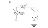
- FIG. 6 is a diagram (No. 6) showing an equivalent circuit used for deriving Equation 1 in the calculation process of the insulation resistance value calculation unit according to the first embodiment.
- FIG. 8 shows the equivalent circuit used for the derivation of the equation 1 in the calculation process of the insulation resistance value calculation part by 1st form. It is a figure which shows the motor drive device (second form) by one Embodiment of this disclosure. It is a figure (the 1) which shows the equivalent circuit used for the derivation of the equation 11 in the calculation process of the insulation resistance value calculation part by 2nd form. It is a figure (No. 2) which shows the equivalent circuit used for the derivation of the equation 11 in the calculation process of the insulation resistance value calculation part by 2nd form.
- FIG. 3 is a diagram (No. 3) showing an equivalent circuit used for deriving Equation 11 in the calculation process of the insulation resistance value calculation unit according to the second embodiment.
- FIG. 5 is a diagram (No. 5) showing an equivalent circuit used for deriving Equation 11 in the calculation process of the insulation resistance value calculation unit according to the second embodiment.
- FIG. 6 is a diagram (No. 6) showing an equivalent circuit used for deriving Equation 11 in the calculation process of the insulation resistance value calculation unit according to the second embodiment.
- FIG. 7 is a diagram (No. 7) showing an equivalent circuit used for deriving Equation 11 in the calculation process of the insulation resistance value calculation unit according to the second embodiment.
- It is a flowchart which shows the operation flow of the motor drive device by one Embodiment of this disclosure. It is a figure explaining the simulation result of the positive potential and the negative potential of a DC link in the case where the AC power source and the motor drive device by one Embodiment of this disclosure are connected by the delta connection.
- FIG. 1 is a diagram showing a motor drive device (first embodiment) according to an embodiment of the present disclosure.
- one end of the measurement resistor 14 is connected to a negative potential line or a positive potential line of the DC link.
- the form in which one end of the measuring resistor 14 is connected to the negative potential line of the DC link is referred to as the first form
- the form in which one end of the measuring resistor 14 is connected to the positive potential line of the DC link is referred to as the second form.
- the first form and the second form differ only in that one end of the measuring resistor 14 is connected to the negative potential line or the positive potential line of the DC link.
- the type of the motor 3 is not particularly limited, and may be, for example, an induction motor or a synchronous motor.
- the number of phases of the AC power supply 2 and the motor 3 is not particularly limited to this embodiment, and may be, for example, three-phase or single-phase.
- the AC power supply 2 and the motor 3 have three phases, respectively.
- Examples of the AC power supply 2 include a three-phase AC 400V power supply, a three-phase AC 200V power supply, a three-phase AC 600V power supply, and a single-phase AC 100V power supply.
- Machines provided with the motor 3 include, for example, machine tools, robots, forging machines, injection molding machines, industrial machines, various electric appliances, trains, automobiles, aircraft and the like.
- the motor drive device 1 includes a converter unit 11, a DC link capacitor 4, an inverter unit 12, and two voltage dividing resistors 13-1 and 13-2. It includes a measurement resistance 14, a resistance voltage measuring unit 15, a DC component extraction unit 16, an AC component extraction unit 17, a DC link potential measurement unit 18, and an insulation resistance value calculation unit 19.
- the converter unit 11 converts the AC power input from the AC power supply 2 into DC power and outputs it to the DC link on the DC output side.
- the converter unit 11 is composed of a three-phase bridge circuit when three-phase AC power is supplied from the AC power supply 2, and is composed of a single-phase bridge circuit when single-phase AC power is supplied from the AC power supply 2.
- the converter unit 11 since the AC power supply 2 is a three-phase AC power supply, the converter unit 11 is composed of a three-phase bridge circuit.
- Examples of the converter unit 11 include a diode rectifier, a 120-degree energization type rectifier, a PWM switching control type rectifier, and the like.
- the converter unit 11 when the converter unit 11 is a 120-degree energization type rectifier and a PWM switching control type rectifier, it is composed of a switching element and a bridge circuit of a diode connected in antiparallel to the switching element, and receives from a host control device (not shown). Each switching element is controlled on and off according to the drive command, and power conversion is performed in both AC and DC directions.
- the switching element include an FET, an IGBT, a thyristor, a GTO (Gate Turn-OFF thyristor), a transistor, and the like, but other semiconductor elements may be used.
- the inverter unit 12 converts the DC power in the DC link into AC power for driving the motor 3 and outputs it.
- the inverter unit 12 includes a switching element and a bridge circuit of a diode connected in antiparallel to the switching element.
- the inverter unit 12 is composed of a three-phase bridge circuit when the motor 3 is a three-phase AC motor, and is composed of a single-phase bridge circuit when the motor 3 is a single-phase AC motor. In the illustrated example, since the motor 3 is a three-phase AC motor, the inverter unit 12 is composed of a three-phase bridge circuit.
- the power conversion operation of the inverter unit 12 is controlled by, for example, a PWM switching control method.
- the inverter unit 12 receives a PWM switching command from a higher-level control device (not shown), converts the DC power in the DC link into AC power for driving the motor 3, outputs it to the motor 3, and regenerates the motor. Occasionally, the AC power regenerated by the motor 3 is converted into DC power and returned to the DC link side.
- the power conversion operation of the inverter unit 12 is controlled by a higher-level control device (not shown). That is, the host control device determines the speed of the motor 3 based on the speed of the motor 3 (speed feedback), the current flowing through the winding of the motor 3 (current feedback), a predetermined torque command, the operation program of the motor 3, and the like. Generates a switching command to control the torque or the position of the rotor. The power conversion operation by the inverter unit 12 is controlled based on the PWM switching command created by the host control device.
- a DC link capacitor 4 is provided on the DC link connecting the DC output side of the converter unit 11 and the DC input side of the inverter unit 12.
- the DC link capacitor 4 has a function of suppressing the pulsation of the DC output of the converter unit 11 and a function of storing the DC power used by the inverter unit 12 to generate AC power.
- Examples of the DC link capacitor 4 include, for example, an electrolytic capacitor and a film capacitor.
- Two voltage dividing resistors 13-1 and 13-2 connected in series with each other are provided between the positive potential line and the negative potential line constituting the DC link.
- the DC link voltage which is the potential difference between the positive potential in the positive potential line of the DC link and the negative potential in the negative potential line, is divided by the voltage dividing resistor 13-1 and the voltage dividing resistor 13-2.
- the connection point between the voltage dividing resistor 13-1 and the voltage dividing resistor 13-2 is connected to the winding (input terminal) of the motor 3.
- each of the voltage dividing resistors 13-1 and 13-2 is each of two DC link resistors connected in series with each other connected between the positive potential line and the negative potential line of the DC link. It is composed of.
- the DC link resistor is composed of a general resistor. It is preferable that the resistance value of the voltage dividing resistor 13-1 and the resistance value of the voltage dividing resistor 13-2 are substantially equal, and in the example shown in FIG. 1, the resistance value is R. However, the resistance value of the voltage dividing resistor 13-1 and the resistance value of the voltage dividing resistor 13-2 may have different values. The resistance values R of the voltage dividing resistors 13-1 and 13-2 may be measured in advance, or the values specified in the standard table for the voltage dividing resistors 13-1 and 13-2 may be used.
- the measuring resistor 14 is connected between the connection point between the voltage dividing resistor 13-1 and the voltage dividing resistor 13-2 and the positive or negative potential line of the DC link.
- FIG. 1 shows a first mode in which the measurement resistor 14 is connected between the connection point between the voltage dividing resistor 13-1 and the voltage dividing resistor 13-2 and the negative potential line of the DC link.
- the measuring resistor 14 is composed of a general resistor. Let the resistance value of the measurement resistor 14 be R in .
- the resistance value R in of the measuring resistor 14 may be measured in advance or may be a value specified in the standard table for the measuring resistor 14.
- the resistance voltage measuring unit 15 is a resistance voltage which is a potential difference between both ends of the measuring resistor 14 in a state where the power conversion operation by the inverter unit 12 is stopped (that is, a state where all the switching elements in the inverter unit 12 are turned off). To measure.
- the signal relating to the resistance voltage of the measurement resistor 14 measured by the resistance voltage measuring unit 15 is sent to the DC component extraction unit 16 and the AC component extraction unit 17.
- the DC component extraction unit 16 extracts a DC component from the resistance voltage measured by the resistance voltage measuring unit 15.
- the DC component extraction unit 16 is composed of, for example, a low-pass filter that removes an AC component from a signal output from the resistance voltage measuring unit 15 and outputs a DC component.
- the signal relating to the DC component of the resistance voltage extracted by the DC component extraction unit 16 is sent to the insulation resistance value calculation unit 19.
- the AC component extraction unit 17 extracts an AC component from the resistance voltage measured by the resistance voltage measuring unit 15.
- the AC component extraction unit 17 is composed of, for example, a high-pass filter that removes a DC component from a signal output from the resistance voltage measuring unit 15 and outputs an AC component.
- the signal relating to the AC component of the resistance voltage extracted by the AC component extraction unit 17 is sent to the insulation resistance value calculation unit 19.
- the DC link potential measuring unit 18 has a positive potential and a negative potential in the positive potential line of the DC link in a state where the power conversion operation by the inverter unit 12 is stopped (that is, a state in which all switching elements in the inverter unit 12 are turned off). Measure the negative potential in the potential line.
- the signals relating to the positive potential and the negative potential of the DC link measured by the DC link potential measuring unit 18 are sent to the insulation resistance value calculation unit 19.
- the insulation resistance value calculation unit 19 was measured by the DC component of the resistance voltage extracted by the DC component extraction unit 16, the AC component of the resistance voltage extracted by the AC component extraction unit 17, and the DC link potential measurement unit 18. Based on the positive and negative potentials of the DC link, the insulation resistance value R m , which is the resistance value of the insulation resistance 20 between the winding of the motor 3 and the ground, is calculated. The details of the calculation process by the insulation resistance value calculation unit 19 will be described later.
- each of the voltage dividing resistors 13-1 and 13-2 is connected in series with each other connected between the positive potential line and the negative potential line of the DC link. It is composed of each of the DC link resistors.
- the off resistance of the switching element in the bridge circuit in the inverter unit 12 may be diverted as the voltage dividing resistors 13-1 and 13-2.
- FIG. 2 is a diagram showing a modified example of the motor drive device (first embodiment) according to the embodiment of the present disclosure.
- the off resistance of the switching element of the upper arm and the lower arm in the same phase has a function of dividing the DC link voltage
- the off resistance of the switching element of the upper arm and the lower arm in the same phase is divided into the voltage dividing resistance 13. It can be used as -1 and 13-2.
- the resistance value of the off resistance of the switching element is R.
- the resistance value R of the off resistance of the switching element may be calculated based on the measurement result of the voltage when the switching element is off.
- one end of the measurement resistance 14 is connected to the negative potential line of the DC link, and one end of the measurement resistance 14 is the positive potential line of the DC link.
- the second form connected to the above will be described separately.
- FIGS. 1 and 2 show the first form in which one end of the measuring resistor 14 is connected to the negative potential line of the DC link, that is, the measuring resistor 14 is a voltage dividing resistor 13-. It is connected between the connection point between 1 and the voltage dividing resistor 13-2 and the negative potential line of the DC link.
- the insulation resistance value calculation unit 19 calculates the insulation resistance value R m of the motor 3 according to the equation 1.
- the resistance value of the measurement resistance 14 is R in
- the positive potential value of the DC link measured by the DC link potential measurement unit 18 when the power conversion operation by the inverter unit 12 is stopped is V p
- the inverter unit 12 is used.
- V n be the value of the negative potential of the DC link measured by the DC link potential measuring unit 18 when the power conversion operation is stopped.
- the value of the DC component of the resistance voltage when the power conversion operation by the inverter unit 12 extracted by the DC component extraction unit 16 (low pass filter) is stopped is extracted by V inL and the AC component extraction unit 17 (high pass filter).
- V in H be the value of the AC component of the resistance voltage when the power conversion operation by the inverter unit 12 is stopped. Further, the value V com is (V p + V n ) / 2, and the value V dif is (V p ⁇ V n ) / 2.
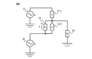
- 3 to 10 are diagrams showing an equivalent circuit used for deriving Equation 1 in the calculation process of the insulation resistance value calculation unit according to the first embodiment.
- the insulation resistance value R m the insulation resistance value calculation unit 19
- the data measured by the resistance voltage measurement unit 15 and the DC link potential measurement unit 18 in a state where the power conversion operation by the inverter unit 12 is stopped is used. .. In the state where the power conversion operation by the inverter unit 12 is stopped, the circuit related to the inverter unit 12 does not appear in FIGS. 3 to 10.
- the positive potential V p in the positive potential line of the DC link shown in FIGS. 1 and 2 is represented by the equivalent power supply 31 in FIG.
- the negative potential V n in the negative potential line of the DC link shown in FIGS. 1 and 2 is represented by the equivalent power supply 32 in FIG.
- the voltage dividing resistors 13-1 and 13-2 shown in FIGS. 1 and 2 the measuring resistor 14 and the insulating resistor 20 of the motor 3 are connected to the equivalent power supplies 31 and 32 as shown in FIG. Will be done.
- the resistance values of the voltage dividing resistors 13-1 and 13-2 are R
- the resistance value of the measuring resistor 14 is R in
- the resistance value of the insulation resistance 20 of the motor 3 is R m .
- the value of the resistance voltage of the measurement resistor 14 measured by the resistance voltage measuring unit 15 is defined as V in .
- the equivalent power supply 32 since the equivalent power supply 32 is connected to one end of the voltage dividing resistor 13-2 and one end of the measuring resistor 14, the equivalent power supply 32 has the same voltage value V as shown in FIG. It can be decomposed into two equivalent power supplies 32 and 33 having n. That is, as shown in FIG. 4, the equivalent power supply 32 is connected to one end of the voltage dividing resistor 13-2, and the equivalent power supply 33 is connected to one end of the measuring resistor 14.
- the equivalent power supplies 37 and 38 as shown in FIG. 8 are obtained.
- the voltage value V 4 of the equivalent power supply 37 is a differential component and is represented by the equation 6.
- the voltage value V 5 of the equivalent power supply 38 is an in-phase component and is represented by the equation 7.
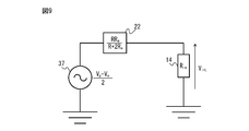
- the equivalent circuit shown in FIG. 8 can be divided into the equivalent circuit of the DC component shown in FIG. 9 and the equivalent circuit of the AC component shown in FIG.
- the equivalent resistor 22 and the measurement resistor 14 are connected to the equivalent power supply 37 having the differential component V 4.
- the voltage component V in L applied to the measuring resistor 14 is obtained using Ohm's law, it is expressed as in Equation 8.
- the signal component (V p + V n ) / 2 containing no DC component is replaced with V com
- the signal component (V p ⁇ V n ) / 2 containing a DC component is replaced with V dif.
- the voltage component V in L corresponds to the DC component obtained by removing the AC component from the resistance voltage of the measurement resistor 14 measured by the resistance voltage measuring unit 15 by the DC component extracting unit 16 (low-pass filter).
- the equivalent resistor 22 and the measurement resistor 14 are connected to the equivalent power supply 38 having the in- phase component V 5.
- the voltage component V in H applied to the measuring resistor 14 is obtained using Ohm's law, it is expressed as in Equation 9.
- the signal component (V p + V n ) / 2 containing no DC component is replaced with V com
- the signal component (V p ⁇ V n ) / 2 containing a DC component is replaced with V dif.
- the voltage component V in H corresponds to the AC component obtained by removing the DC component from the resistance voltage of the measurement resistor 14 measured by the resistance voltage measuring unit 15 by the AC component extracting unit 17 (high-pass filter).
- the insulation resistance value calculation unit 19 calculates the insulation resistance value R m of the motor 3 according to Equation 1.
- the value V com is represented by (V p + V n ) / 2
- the value V dif is represented by (V p ⁇ V n ) / 2.
- V p is a positive potential in the positive potential line of the DC link measured by the DC link potential measuring unit 18 when the power conversion operation by the inverter unit 12 is stopped.
- V n is a negative potential in the negative potential line of the DC link measured by the DC link potential measuring unit 18 when the power conversion operation by the inverter unit 12 is stopped.
- the DC component V in L is obtained by removing the AC component from the resistance voltage of the measurement resistor 14 measured by the resistance voltage measuring unit 15 when the power conversion operation by the inverter unit 12 is stopped by the DC component extracting unit 16 (low-pass filter). can get.
- the AC component V in H is obtained by removing the DC component from the resistance voltage of the measurement resistor 14 measured by the resistance voltage measuring unit 15 when the power conversion operation by the inverter unit 12 is stopped by the AC component extracting unit 17 (high-pass filter). can get.
- the resistance value R in of the measurement resistor 14 may be measured in advance or a value specified in the standard table may be used. Further, each resistance value R of the voltage dividing resistors 13-1 and 13-2 can be obtained by solving the simultaneous equations of the equations 8 and 9. That is, "calculating the insulation resistance value R m of the motor 3 according to Equation 1" means " the DC component V in L of the resistance voltage extracted by the DC component extraction unit 16 and the resistance extracted by the AC component extraction unit 17.” It means that the insulation resistance value R m of the motor 3 is calculated based on the AC component V in H of the voltage and the positive potential V p and the negative potential V n of the DC link measured by the DC link potential measuring unit 18. " do.
- the value V com and the AC component V in H , and the value V dif and the DC component V in L may be measured after being converted into direct current through a rectifier circuit.
- the AC component V in H of the resistance voltage extracted by the AC component extraction unit 17 is rectified and then an absolute value is taken, and the insulation resistance value R m of the motor 3 is calculated according to the equation 10 based on this value.
- the AC component V in H of the resistance voltage extracted by the AC component extraction unit 17 is rectified and then the absolute value is taken, and the DC component V in L of the resistance voltage extracted by the DC component extraction unit 16 is rectified.
- FIG. 11 is a diagram showing a motor drive device (second embodiment) according to an embodiment of the present disclosure.
- the measuring resistor 14 is connected between the connection point between the voltage dividing resistor 13-1 and the voltage dividing resistor 13-2 and the positive potential line of the DC link. Since the other circuit components are the same as those shown in FIG. 1, the same circuit components are designated by the same reference numerals and detailed description of the circuit components will be omitted.
- the off resistance of the switching element in the bridge circuit in the inverter unit 12 may be diverted as the voltage dividing resistors 13-1 and 13-2.
- the insulation resistance value calculation unit 19 calculates the insulation resistance value R m of the motor 3 according to the equation 11.
- the resistance value of the measurement resistance 14 is R in
- the positive potential value of the DC link measured by the DC link potential measurement unit 18 when the power conversion operation by the inverter unit 12 is stopped is V p
- the inverter unit 12 is used.
- V n be the value of the negative potential of the DC link measured by the DC link potential measuring unit 18 when the power conversion operation is stopped.
- the value of the DC component of the resistance voltage when the power conversion operation by the inverter unit 12 extracted by the DC component extraction unit 16 (low pass filter) is stopped is extracted by V inL and the AC component extraction unit 17 (high pass filter).
- V in H be the value of the AC component of the resistance voltage when the power conversion operation by the inverter unit 12 is stopped. Further, the value V com is (V p + V n ) / 2, and the value V dif is (V p ⁇ V n ) / 2.
- 12 to 18 are diagrams showing an equivalent circuit used for deriving Equation 11 in the calculation process of the insulation resistance value calculation unit according to the second embodiment.
- the positive potential V p in the positive potential line of the DC link shown in FIG. 11 is represented by the equivalent power supply 51 in FIG.
- the negative potential V n in the negative potential line of the DC link shown in FIG. 3 is represented by the equivalent power supply 52 in FIG.
- the voltage dividing resistors 13-1 and 13-2 shown in FIG. 11, the measuring resistor 14, and the insulating resistor 20 of the motor 3 are connected to the equivalent power supplies 51 and 52 as shown in FIG.
- the resistance values of the voltage dividing resistors 13-1 and 13-2 are R
- the resistance value of the measuring resistor 14 is R in
- the resistance value of the insulation resistance 20 of the motor 3 is R m .
- the value of the resistance voltage of the measurement resistor 14 measured by the resistance voltage measuring unit 15 is defined as V in .
- the equivalent power supplies 57 and 58 as shown in FIG. 16 are obtained.
- the voltage value V 9 of the equivalent power supply 57 is a differential component and is represented by the equation 16.
- the voltage value V 10 of the equivalent power supply 58 is an in-phase component and is represented by the equation 17.
- the equivalent circuit shown in FIG. 16 can be divided into an equivalent circuit of a DC component shown in FIG. 17 and an equivalent circuit of an AC component shown in FIG.
- the equivalent resistor 42 and the measurement resistor 14 are connected to the equivalent power supply 57 having the differential component V 9.
- the voltage component V in L applied to the measuring resistor 14 is obtained using Ohm's law, it is expressed by Equation 18.
- the signal component (V p + V n ) / 2 containing no DC component is replaced with V com
- the signal component (V p ⁇ V n ) / 2 containing a DC component is replaced with V dif.
- the voltage component V in L corresponds to the DC component obtained by removing the AC component from the resistance voltage of the measurement resistor 14 measured by the resistance voltage measuring unit 15 by the DC component extracting unit 16 (low-pass filter).
- the equivalent resistor 42 and the measurement resistor 14 are connected to the equivalent power supply 58 having the in- phase component V 10.
- the voltage component V in H applied to the measuring resistor 14 is obtained by using Ohm's law, it is expressed by Equation 19.
- the signal component (V p + V n ) / 2 containing no DC component is replaced with V com
- the signal component (V p ⁇ V n ) / 2 containing a DC component is replaced with V dif.
- the voltage component V in H corresponds to the AC component obtained by removing the DC component from the resistance voltage of the measurement resistor 14 measured by the resistance voltage measuring unit 15 by the AC component extracting unit 17 (high-pass filter).
- the insulation resistance value calculation unit 19 calculates the insulation resistance value R m of the motor 3 according to the equation 11.
- the value V com is represented by (V p + V n ) / 2
- the value V dif is represented by (V p ⁇ V n ) / 2.
- V p is a positive potential in the positive potential line of the DC link measured by the DC link potential measuring unit 18 when the power conversion operation by the inverter unit 12 is stopped.
- V n is a negative potential in the negative potential line of the DC link measured by the DC link potential measuring unit 18 when the power conversion operation by the inverter unit 12 is stopped.
- the DC component V in L is obtained by removing the AC component from the resistance voltage of the measurement resistor 14 measured by the resistance voltage measuring unit 15 when the power conversion operation by the inverter unit 12 is stopped by the DC component extracting unit 16 (low-pass filter). can get.
- the AC component V in H is obtained by removing the DC component from the resistance voltage of the measurement resistor 14 measured by the resistance voltage measuring unit 15 when the power conversion operation by the inverter unit 12 is stopped by the AC component extracting unit 17 (high-pass filter). can get.
- the resistance value R in of the measurement resistor 14 may be measured in advance or a value specified in the standard table may be used. Further, each resistance value R of the voltage dividing resistors 13-1 and 13-2 can be obtained by solving the simultaneous equations of the equations 18 and 19. That is, "calculating the insulation resistance value R m of the motor 3 according to the equation 11" means " the DC component V in L of the resistance voltage extracted by the DC component extraction unit 16 and the resistance extracted by the AC component extraction unit 17.” It means that the insulation resistance value R m of the motor 3 is calculated based on the AC component V in H of the voltage and the positive potential V p and the negative potential V n of the DC link measured by the DC link potential measuring unit 18. " do.
- the value V com and the AC component V in H , and the value V dif and the DC component V in L may be measured after being converted into direct current through a rectifier circuit.
- the AC component V in H of the resistance voltage extracted by the AC component extraction unit 17 is rectified and then an absolute value is taken, and the AC component V in H of the resistance voltage extracted by the equation 20 is rectified based on this value.
- the absolute value is taken and the DC component V in L of the resistance voltage extracted by the DC component extraction unit 16 is rectified and then the absolute value is taken.
- the insulation resistance value R of the motor 3 is calculated according to the equation 20. Calculate m. Since the absolute values of the AC component V in H of the formula 19 and the DC component V in L of the formula 18 are taken, the sign of the formula 20 is partially different from that of the formula 11.
- the measurement process by the resistance voltage measuring unit 15 and the measurement process by the DC link potential measuring unit 18 stopped the power conversion operation by the inverter unit 12. It is executed in a state (that is, a state in which all the switching elements in the inverter unit 12 are turned off), and the insulation resistance value calculation unit 19 calculates the insulation resistance value R m based on the data measured at this time. That is, according to one embodiment of the present disclosure, the resistance voltage measuring unit 15, the DC component extracting unit 16, the AC component extracting unit 17, and the DC link potential measuring unit 18 are in a state where the power conversion operation by the inverter unit 12 is stopped. , And the insulation resistance value R m of the motor 3 can be measured by operating the insulation resistance value calculation unit 19.
- the insulation resistance value R m calculated by the insulation resistance value calculation unit 19 may be displayed on, for example, a display unit (not shown). As a result, the operator can quickly and easily grasp the insulation resistance value R m of the motor 3.
- a determination unit for determining the insulation deterioration of the motor 3 by comparing the insulation resistance value R m calculated by the insulation resistance value calculation unit 19 with a threshold value as a criterion for determining insulation deterioration is provided.
- the display unit include a single display device, a display device attached to the motor drive device 1, and a display device attached to a personal computer and a mobile terminal.
- an audio device that emits a sound such as a voice, a speaker, a buzzer, a chime, etc.
- the operator is notified that "insulation deterioration has occurred in the motor 3". You may do so.
- the operator can quickly and easily grasp that the insulation deterioration has occurred in the motor 3. Therefore, it becomes easy for the operator to take measures such as replacement or repair of the motor 3.
- the DC component extraction unit 16, the AC component extraction unit 17, the insulation resistance value calculation unit 19, and the host control device may be composed of a combination of an analog circuit and an arithmetic processing unit, or may be composed of only an arithmetic processing unit. It may be composed of only an analog circuit.
- the DC component when constructing the DC component extraction unit 16, the AC component extraction unit 17, the insulation resistance value calculation unit 19, and the host control device in the form of a software program, the DC component can be operated by operating the arithmetic processing unit according to this software program.
- Each function of the extraction unit 16, the AC component extraction unit 17, the insulation resistance value calculation unit 19, and the host control device can be realized.
- the DC component extraction unit 16, the AC component extraction unit 17, the insulation resistance value calculation unit 19, and the host control device may be realized as a semiconductor integrated circuit in which a software program for realizing the functions of each unit is written.
- the DC component extraction unit 16, the AC component extraction unit 17, the insulation resistance value calculation unit 19, and the host control device may be realized as a recording medium in which a software program that realizes the functions of each unit is written.
- the DC component extraction unit 16, the AC component extraction unit 17, the insulation resistance value calculation unit 19, and the host control device may be provided in, for example, a numerical control device of a machine tool, and may be provided in a robot controller that controls the robot. It may be provided.
- the resistance voltage measuring unit 15 and the DC link potential measuring unit 18 may be configured by a combination of an analog circuit and an arithmetic processing device, may be composed of only an arithmetic processing device, or may be composed of only an analog circuit. May be good.
- FIG. 19 is a flowchart showing an operation flow of the motor drive device according to the embodiment of the present disclosure.
- the flowchart shown in FIG. 19 is applicable to any of the motor drive devices 1 of the first embodiment and the second embodiment.
- step S101 the host control device (not shown) turns off all the switching elements in the inverter unit 12 and performs the power conversion operation by the inverter unit 12. Stop it.
- step S102 the resistance voltage measuring unit 15 measures the resistance voltage V in , which is the potential difference between both ends of the measuring resistor 14.
- Signal related resistor voltage V in of the resistance voltage measurement unit 15 measuring resistor 14 measured by is sent to the DC component extractor 16 and the AC component extractor 17.
- step S103 the DC component extraction unit 16 extracts the DC component V in L from the resistance voltage V in measured by the resistance voltage measuring unit 15.
- the signal relating to the DC component V in L of the resistance voltage extracted by the DC component extraction unit 16 is sent to the insulation resistance value calculation unit 19.
- step S104 the AC component extraction unit 17 extracts the AC component V in H from the resistance voltage V in measured by the resistance voltage measuring unit 15.
- the signal regarding the AC component V in H of the resistance voltage extracted by the AC component extraction unit 17 is sent to the insulation resistance value calculation unit 19.
- step S103 and the process of step S104 may be executed by changing the order.
- step S105 the DC link potential measuring unit 18 measures the positive potential V p in the positive potential line of the DC link and the negative potential V n in the negative potential line.
- the signals relating to the positive potential V p and the negative potential V n of the DC link measured by the DC link potential measuring unit 18 are sent to the insulation resistance value calculation unit 19.
- steps S102 to S104 and the processing of step S105 may be executed in a different order.
- the insulation resistance value calculation unit 19 has a DC component V in L of the resistance voltage extracted by the DC component extraction unit 16, an AC component V in H of the resistance voltage extracted by the AC component extraction unit 17, and a DC link.
- the insulation resistance value R m of the motor 3 is calculated based on the positive potential V p and the negative potential V n of the DC link measured by the potential measuring unit 18.
- the insulation resistance value calculation unit 19 calculates the insulation resistance value R m of the motor 3 according to the equation 1.
- the insulation resistance value calculation unit 19 calculates the insulation resistance value R m of the motor 3 according to the equation 11.
- the insulation resistance value R m calculated by the insulation resistance value calculation unit 19 may be displayed on a display unit (not shown). Further, for example, a determination unit (not shown) for determining the insulation deterioration of the motor 3 by comparing the insulation resistance value R m calculated by the insulation resistance value calculation unit 19 with a threshold value as a criterion for determining insulation deterioration is provided for determination. When it is determined by the unit that the insulation resistance value R m exceeds the threshold value, "the insulation deterioration has occurred in the motor 3" may be displayed on the display unit. Further, for example, in an audio device that emits a sound such as a voice, a speaker, a buzzer, a chime, etc. together with or instead of the display unit, the operator is notified that "insulation deterioration has occurred in the motor 3". You may do so.
- FIG. 20 is a diagram for explaining the simulation results of the positive potential and the negative potential of the DC link when the AC power supply and the motor drive device according to the embodiment of the present disclosure are connected by the delta connection.
- Equations 1 and 11 when calculating the insulation resistance value R m , the values V com represented by (V p + V n ) / 2 and V represented by (V p ⁇ V n ) / 2. dif is used.
- V p ⁇ V n between the positive potential V p and the negative potential V n is constant, it functions as a DC component, and is the sum of the positive potential V p and the negative potential V n. Since "V p + V n " is constant, it can be seen that it functions as an AC component.
Landscapes
- Physics & Mathematics (AREA)
- General Physics & Mathematics (AREA)
- Engineering & Computer Science (AREA)
- Power Engineering (AREA)
- Control Of Ac Motors In General (AREA)
- Tests Of Circuit Breakers, Generators, And Electric Motors (AREA)
- Control Of Electric Motors In General (AREA)
Abstract
モータ駆動装置1は、入力された交流電力を直流電力に変換してDCリンクへ出力するコンバータ部11と、DCリンクコンデンサ4と、DCリンクの正電位線と負電位線との間に設けられる互いに直列接続された分圧抵抗13-1、13-2と、分圧抵抗13-1及び13-2の接続点とDCリンクの正電位線又は負電位線との間に接続された測定用抵抗14と、測定用抵抗14の抵抗電圧を測定する抵抗電圧測定部15と、抵抗電圧の直流成分を抽出する直流成分抽出部16と、抵抗電圧の交流成分を抽出する交流成分抽出部17と、DCリンクの正電位及び負電位を測定するDCリンク電位測定部18と、抵抗電圧の直流成分及び交流成分とDCリンクの正電位及び負電位とに基づいてモータ3の絶縁抵抗値を計算する絶縁抵抗値計算部19とを備える。
Description
本発明は、モータの絶縁抵抗値を計算するモータ駆動装置に関する。
工作機械、鍛圧機械、射出成形機、産業機械、あるいは各種ロボット内のモータの駆動を制御するモータ駆動装置においては、交流電源から入力される交流電力をコンバータ部(整流回路)にて直流電力に変換してDCリンクへ出力し、さらにインバータ部にてDCリンクにおける直流電圧を交流電力に変換し、この交流電力をモータの駆動電力として供給している。「DCリンク」とは、コンバータ部の直流出力側とインバータ部の直流入力側とを電気的に接続する回路部分のことを指し、「DCリンク部」、「直流リンク」、「直流リンク部」または「直流中間回路」などとも別称されることもある。
何らかの原因によりモータの絶縁劣化によるモータ故障が発生することがある。モータの絶縁劣化の検出は、モータの巻線と大地との間の抵抗値である絶縁抵抗値を測定することにより行われる。
例えば、第1のスイッチを介して交流電源から供給される交流電圧を直流電圧に整流する整流回路と、前記整流回路によって整流された直流電圧をコンデンサで平滑化する電源部と、前記電源部によって平滑化された直流電圧を半導体スイッチング素子のスイッチング動作により交流電圧に変換してモータを駆動するインバータ部と、前記モータのコイルに一端を接続し、前記コンデンサの一方の端子に他端を接続した抵抗器に流れる電流値を測定する電流検出部と、前記コンデンサの両端の電圧値を測定する電圧検出部と、前記コンデンサの他方の端子を接地する第2のスイッチと、モータの運転を停止し、前記第1のスイッチをオフし、かつ、前記第2のスイッチをオフした状態とオンした状態の2つの状態において測定された2組の前記電流値及び前記電圧値を用いて、モータのコイルと大地との間の抵抗であるモータの絶縁抵抗値を検出する絶縁抵抗検出部と、を有することを特徴とするモータ駆動装置が知られている(例えば、特許文献1参照。)。
例えば、運転中の交流電動機における界磁巻線の絶縁劣化の発生を検出する絶縁劣化検出装置であって、交流電動機の各相の界磁巻線での部分放電発生の際の電磁波を個別に検出する複数の検出素子と、その複数の検出素子からの出力信号を一括して接地する接地線と、上記接地線から部分放電信号を取り出す検出手段と、該検出手段の出力信号に基づき部分放電が許容以上か否かを判定する判定手段と、判定手段が許容以上の部分放電と判定すると警報を出力する警報手段とを備えることを特徴とする電動機の絶縁劣化検出装置。が知られている(例えば、特許文献2参照。)。
従来、モータの絶縁抵抗値を測定する際は、当該モータを駆動するモータ駆動装置と交流電源との間を遮断して行う必要があった。しかしながら、モータの絶縁抵抗値の測定のたびにモータ駆動装置と交流電源との遮断作業及び接続作業を行うことは手間及び時間がかかり、効率が悪い。また、モータ駆動装置と交流電源との間に遮断器を設置することも考えられるが、コストが増加するという欠点がある。したがって、モータ駆動装置を交流電源から切り離すことなくモータの絶縁抵抗値を低コストで測定できるようにする技術が望まれている。
本開示の一態様によれば、モータ駆動装置は、交流電源から入力された交流電力を直流電力に変換してDCリンクへ出力するコンバータ部と、DCリンクに設けられるDCリンクコンデンサと、DCリンクにおける直流電力をモータの駆動のための交流電力に変換して出力するインバータ部と、DCリンクを構成する正電位線と負電位線との間に設けられる互いに直列接続された2つの分圧抵抗であって分圧抵抗どうしの接続点とモータの巻線とが接続される分圧抵抗と、分圧抵抗どうしの接続点とDCリンクの正電位線または負電位線との間に接続される測定用抵抗と、測定用抵抗の両端の電位差である抵抗電圧を測定する抵抗電圧測定部と、抵抗電圧測定部により測定された抵抗電圧から直流成分を抽出する直流成分抽出部と、抵抗電圧測定部により測定された抵抗電圧から交流成分を抽出する交流成分抽出部と、DCリンクの正電位線における正電位及び負電位線における負電位を測定するDCリンク電位測定部と、直流成分抽出部により抽出された直流成分と交流成分抽出部により抽出された交流成分とDCリンク電位測定部により測定された正電位及び負電位とに基づいて、モータの絶縁抵抗値を計算する絶縁抵抗値計算部とを備える。
本開示の一態様によれば、モータ駆動装置を交流電源から切り離すことなくモータの絶縁抵抗値を低コストで測定できる。
以下図面を参照して、モータの絶縁抵抗値を計算するモータ駆動装置について説明する。各図面において、同様の部材には同様の参照符号が付けられている。また、理解を容易にするために、これらの図面は縮尺を適宜変更している。また、図面に示される形態は実施するための一つの例であり、図示された形態に限定されるものではない。
図1は、本開示の一実施形態によるモータ駆動装置(第1の形態)を示す図である。なお、詳細については後述するが、測定用抵抗14の一端はDCリンクの負電位線または正電位線に接続される。測定用抵抗14の一端がDCリンクの負電位線に接続される形態を第1の形態と称し、測定用抵抗14の一端がDCリンクの正電位線に接続される形態を第2の形態と称する。第1の形態と第2の形態とは、測定用抵抗14の一端がDCリンクの負電位線に接続されるか正電位線に接続されるかの点でのみ相違する。
一例として、交流電源2に接続されたモータ駆動装置1により、モータ3を制御する場合について示す。本実施形態においては、モータ3の種類は特に限定されず、例えば誘導モータであっても同期モータであってもよい。また、交流電源2及びモータ3の相数は本実施形態を特に限定するものではなく、例えば三相であっても単相であってもよい。図示の例では、交流電源2及びモータ3をそれぞれ三相としている。交流電源2の一例を挙げると、三相交流400V電源、三相交流200V電源、三相交流600V電源、単相交流100V電源などがある。モータ3が設けられる機械には、例えば工作機械、ロボット、鍛圧機械、射出成形機、産業機械、各種電化製品、電車、自動車、航空機などが含まれる。
図1に示すように、本開示の一実施形態によるモータ駆動装置1は、コンバータ部11と、DCリンクコンデンサ4と、インバータ部12と、2つの分圧抵抗13-1及び13-2と、測定用抵抗14と、抵抗電圧測定部15と、直流成分抽出部16と、交流成分抽出部17と、DCリンク電位測定部18と、絶縁抵抗値計算部19とを備える。
コンバータ部11は、交流電源2から入力された交流電力を直流電力に変換して直流出力側であるDCリンクへ出力する。コンバータ部11は、交流電源2から三相交流電力が供給される場合は三相ブリッジ回路で構成され、交流電源2から単相交流電力が供給される場合は単相ブリッジ回路で構成される。図示の例では、交流電源2を三相交流電源としたので、コンバータ部11は三相ブリッジ回路で構成される。コンバータ部11の例としては、ダイオード整流器、120度通電方式整流器、及びPWMスイッチング制御方式整流器などがある。例えば、コンバータ部11が120度通電方式整流器及びPWMスイッチング制御方式整流器である場合は、スイッチング素子及びこれに逆並列に接続されたダイオードのブリッジ回路からなり、上位制御装置(図示せず)から受信した駆動指令に応じて各スイッチング素子がオンオフ制御されて交直双方向に電力変換を行う。この場合、スイッチング素子の例としては、FET、IGBT、サイリスタ、GTO(Gate Turn-OFF thyristor:ゲートターンオフサイリスタ)、トランジスタなどがあるが、その他の半導体素子であってもよい。
インバータ部12は、DCリンクにおける直流電力をモータ3の駆動のための交流電力に変換して出力する。インバータ部12は、スイッチング素子及びこれに逆並列に接続されたダイオードのブリッジ回路からなる。インバータ部12は、モータ3が三相交流モータである場合は三相ブリッジ回路で構成され、モータ3が単相交流モータである場合は単相ブリッジ回路で構成される。図示の例では、モータ3を三相交流モータとしたので、インバータ部12は三相ブリッジ回路で構成される。インバータ部12は、例えばPWMスイッチング制御方式によりその電力変換動作が制御される。すなわち、インバータ部12は、上位制御装置(図示せず)からのPWMスイッチング指令を受けてDCリンクにおける直流電力をモータ3を駆動するための交流電力に変換してモータ3へ出力するとともにモータ回生時にはモータ3で回生された交流電力を直流電力に変換してDCリンク側へ戻す。
一般的なモータ駆動装置と同様、インバータ部12は、上位制御装置(図示せず)により、電力変換動作が制御される。すなわち、上位制御装置は、モータ3の速度(速度フィードバック)、モータ3の巻線に流れる電流(電流フィードバック)、所定のトルク指令、及びモータ3の動作プログラムなどに基づいて、モータ3の速度、トルク、もしくは回転子の位置を制御するためのスイッチング指令を生成する。上位制御装置によって作成されたPWMスイッチング指令に基づいて、インバータ部12による電力変換動作が制御される。
コンバータ部11の直流出力側とインバータ部12の直流入力側とを接続するDCリンクには、DCリンクコンデンサ4が設けられる。DCリンクコンデンサ4は、コンバータ部11の直流出力の脈動分を抑える機能及びインバータ部12が交流電力を生成するために用いられる直流電力を蓄積する機能を有する。DCリンクコンデンサ4の例としては、例えば電解コンデンサやフィルムコンデンサなどがある。
DCリンクを構成する正電位線と負電位線との間には、互いに直列接続された2つの分圧抵抗13-1及び13-2が設けられる。DCリンクの正電位線における正電位と負電位線における負電位との電位差であるDCリンク電圧を、分圧抵抗13-1と分圧抵抗13-2とで分圧する。分圧抵抗13-1と分圧抵抗13-2との接続点は、モータ3の巻線(の入力端子)に接続される。図1に示す例では、分圧抵抗13-1及び13-2の各々は、DCリンクの正電位線と負電位線との間に接続される互いに直列接続された2つのDCリンク抵抗の各々にて構成される。DCリンク抵抗は一般的な抵抗にて構成される。分圧抵抗13-1の抵抗値と分圧抵抗13-2の抵抗値とは、略等しいことが好ましく、図1に示す例では抵抗値をRとしている。ただし、分圧抵抗13-1の抵抗値と分圧抵抗13-2の抵抗値とは、異なった値を有していてもよい。分圧抵抗13-1及び13-2の各抵抗値Rは、予め測定しておくか、あるいは分圧抵抗13-1及び13-2についての規格表に規定された値を用いればよい。
測定用抵抗14は、分圧抵抗13-1と分圧抵抗13-2との接続点と、DCリンクの正電位線または負電位線との間に接続される。図1では、分圧抵抗13-1と分圧抵抗13-2との接続点と、DCリンクの負電位線との間に測定用抵抗14が接続される第1の形態を示している。測定用抵抗14は一般的な抵抗にて構成される。測定用抵抗14の抵抗値をRinとする。測定用抵抗14の抵抗値Rinは、予め測定しておくか、あるいは測定用抵抗14についての規格表に規定された値を用いればよい。
抵抗電圧測定部15は、インバータ部12による電力変換動作を停止させた状態(すなわちインバータ部12内の全てのスイッチング素子をオフさせた状態)において、測定用抵抗14の両端の電位差である抵抗電圧を測定する。抵抗電圧測定部15により測定された測定用抵抗14の抵抗電圧に関する信号は、直流成分抽出部16及び交流成分抽出部17へ送られる。
直流成分抽出部16は、抵抗電圧測定部15により測定された抵抗電圧から直流成分を抽出する。直流成分抽出部16は、例えば抵抗電圧測定部15から出力される信号から交流成分を除去して直流成分を出力するローパスフィルタにて構成される。直流成分抽出部16により抽出された抵抗電圧の直流成分に関する信号は、絶縁抵抗値計算部19へ送られる。
交流成分抽出部17は、抵抗電圧測定部15により測定された抵抗電圧から交流成分を抽出する。交流成分抽出部17は、例えば抵抗電圧測定部15から出力される信号から直流成分を除去して交流成分を出力するハイパスフィルタにて構成される。交流成分抽出部17により抽出された抵抗電圧の交流成分に関する信号は、絶縁抵抗値計算部19へ送られる。
DCリンク電位測定部18は、インバータ部12による電力変換動作を停止させた状態(すなわちインバータ部12内の全てのスイッチング素子をオフさせた状態)において、DCリンクの正電位線における正電位及び負電位線における負電位を測定する。DCリンク電位測定部18により測定されたDCリンクの正電位及び負電位に関する信号は、絶縁抵抗値計算部19へ送られる。
絶縁抵抗値計算部19は、直流成分抽出部16により抽出された抵抗電圧の直流成分と、交流成分抽出部17により抽出された抵抗電圧の交流成分と、DCリンク電位測定部18により測定されたDCリンクの正電位及び負電位とに基づいて、モータ3の巻線と大地との間の絶縁抵抗20の抵抗値である絶縁抵抗値Rmを計算する。絶縁抵抗値計算部19による計算処理の詳細については後述する。
図1を参照して説明した実施形態では、分圧抵抗13-1及び13-2の各々は、DCリンクの正電位線と負電位線との間に接続される互いに直列接続された2つのDCリンク抵抗の各々にて構成される。この変形例として、インバータ部12内のブリッジ回路におけるスイッチング素子のオフ抵抗を、分圧抵抗13-1及び13-2として流用してもよい。図2は、本開示の一実施形態によるモータ駆動装置(第1の形態)の変形例を示す図である。インバータ部12内のブリッジ回路を構成する同一相中の上アーム及び下アームのそれぞれに設けられるスイッチング素子をオフすると、所定の抵抗値を有するオフ抵抗が発生する。同一相中の上アーム及び下アームのスイッチング素子についてのオフ抵抗は、DCリンク電圧を分圧する機能を有するので、同一相中の上アーム及び下アームのスイッチング素子のオフ抵抗を、分圧抵抗13-1及び13-2として用いることができる。本変形例では、スイッチング素子のオフ抵抗の抵抗値をRとする。スイッチング素子のオフ抵抗の抵抗値Rは、スイッチング素子のオフ時の電圧の測定結果に基づいて計算すればよい。
続いて、絶縁抵抗値計算部19における計算処理について、測定用抵抗14の一端がDCリンクの負電位線に接続される第1の形態と、測定用抵抗14の一端がDCリンクの正電位線に接続される第2の形態とに分けて説明する。
まず、測定用抵抗14の一端がDCリンクの負電位線に接続される第1の形態による絶縁抵抗値計算部19における計算処理について説明する。
上述したように、図1及び図2は測定用抵抗14の一端がDCリンクの負電位線に接続される第1の形態を示しており、すなわち、測定用抵抗14は、分圧抵抗13-1と分圧抵抗13-2との接続点とDCリンクの負電位線との間に接続される。
図1及び図2に示す第1の形態では、絶縁抵抗値計算部19は、式1に従って、モータ3の絶縁抵抗値Rmを計算する。式1において、測定用抵抗14の抵抗値をRin、インバータ部12による電力変換動作の停止時にDCリンク電位測定部18により測定されたDCリンクの正電位の値をVp、インバータ部12による電力変換動作の停止時にDCリンク電位測定部18により測定されたDCリンクの負電位の値をVnとする。また、直流成分抽出部16(ローパスフィルタ)により抽出されたインバータ部12による電力変換動作の停止時における抵抗電圧の直流成分の値をVinL、交流成分抽出部17(ハイパスフィルタ)により抽出されたインバータ部12による電力変換動作の停止時における抵抗電圧の交流成分の値をVinHとする。また、値Vcomを(Vp+Vn)/2、値Vdifを(Vp-Vn)/2とする。

ここで、測定用抵抗14の一端がDCリンクの負電位線に接続される第1の形態による絶縁抵抗値計算部19における計算処理において用いられる式1の導出過程について説明する。図3~図10は、第1の形態による絶縁抵抗値計算部の計算処理における式1の導出に用いられる等価回路を示す図である。
絶縁抵抗値計算部19による絶縁抵抗値Rmの算出には、インバータ部12による電力変換動作を停止させた状態において抵抗電圧測定部15及びDCリンク電位測定部18により測定されたデータが用いられる。インバータ部12による電力変換動作を停止させた状態では、図3~図10にはインバータ部12に関する回路は現れない。
図1及び図2に示すDCリンクの正電位線における正電位Vpを、図3では等価電源31で表す。同様に、図1及び図2に示すDCリンクの負電位線における負電位Vnを、図3では等価電源32で表す。このとき、図1及び図2に示す分圧抵抗13-1及び13-2、測定用抵抗14、並びにモータ3の絶縁抵抗20は、等価電源31及び32に対して図3に示すように接続される。分圧抵抗13-1及び13-2の抵抗値をそれぞれRとし、測定用抵抗14の抵抗値をRinとし、モータ3の絶縁抵抗20の抵抗値をRmとする。抵抗電圧測定部15により測定される測定用抵抗14の抵抗電圧の値をVinとする。
図3に示す等価回路において、等価電源32は分圧抵抗13-2の一端及び測定用抵抗14の一端に接続されているので、等価電源32は、図4に示すように同一の電圧値Vnを有する2つの等価電源32及び33に分解することができる。すなわち、図4に示すように、分圧抵抗13-2の一端に等価電源32が接続され、測定用抵抗14の一端に等価電源33が接続される。
図4に示す等価回路において、回路部分T1にテブナンの定理を適用すると、図5に示すような等価回路が得られる。図5において、等価電源34の電圧値V1は式2で表され、等価抵抗21の抵抗値はR/2となる。

図5に示す等価回路において、回路部分T2にテブナンの定理を適用すると、図6に示すような等価回路が得られる。図6において、等価電源35の電圧値V2は式3で表され、等価抵抗22の抵抗値R1は式4で表される。


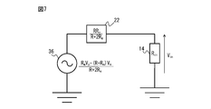
図6に示す等価回路において、等価電源33と等価電源35とは、等価抵抗22及び測定用抵抗14を介して直列に接続されているので、等価電源33と等価電源35とを1つにまとめると、図7に示すような等価電源36が得られる。図7において、等価電源36の電圧値V3は式5で表される。

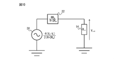
図7に示す等価回路において、等価電源36の電圧値V3を差動成分と同相成分とに分けると、図8に示すような等価電源37及び38が得られる。図8において、等価電源37の電圧値V4は差動成分であり、式6で表される。等価電源38の電圧値V5は同相成分であり、式7で表される。


図8に示す等価回路は、図9に示す直流成分の等価回路と図10に示す交流成分の等価回路とに分けることができる。
図9に示すように直流成分の等価回路では、差動成分V4を有する等価電源37に等価抵抗22及び測定用抵抗14が接続される。オームの法則を用いて測定用抵抗14に印加される電圧成分VinLを求めると、式8のように表される。式8において、直流成分を含まない信号成分である(Vp+Vn)/2をVcom、直流成分を含む信号成分(Vp-Vn)/2をVdifに置き換えている。電圧成分VinLは、抵抗電圧測定部15により測定された測定用抵抗14の抵抗電圧から直流成分抽出部16(ローパスフィルタ)により交流成分を除去することで得られる直流成分に対応する。

図10に示すように交流成分の等価回路では、同相成分V5を有する等価電源38に等価抵抗22及び測定用抵抗14が接続される。オームの法則を用いて測定用抵抗14に印加される電圧成分VinHを求めると、式9のように表される。式9において、直流成分を含まない信号成分である(Vp+Vn)/2をVcom、直流成分を含む信号成分(Vp-Vn)/2をVdifに置き換えている。電圧成分VinHは、抵抗電圧測定部15により測定された測定用抵抗14の抵抗電圧から交流成分抽出部17(ハイパスフィルタ)により直流成分を除去することで得られる交流成分に対応する。

式8及び式9についての連立方程式を絶縁抵抗値Rmについて解くことで、絶縁抵抗値Rmを求めるための式1が得られる。測定用抵抗14の一端がDCリンクの負電位線に接続される第1の形態では、絶縁抵抗値計算部19は、式1に従って、モータ3の絶縁抵抗値Rmを計算する。式1において、値Vcomは(Vp+Vn)/2によって表され、値Vdifは(Vp-Vn)/2によって表される。Vpは、インバータ部12による電力変換動作の停止時にDCリンク電位測定部18により測定されるDCリンクの正電位線における正電位である。Vnは、インバータ部12による電力変換動作の停止時にDCリンク電位測定部18により測定されるDCリンクの負電位線における負電位である。直流成分VinLは、インバータ部12による電力変換動作の停止時に抵抗電圧測定部15により測定された測定用抵抗14の抵抗電圧から直流成分抽出部16(ローパスフィルタ)により交流成分を除去することで得られる。交流成分VinHは、インバータ部12による電力変換動作の停止時に抵抗電圧測定部15により測定された測定用抵抗14の抵抗電圧から交流成分抽出部17(ハイパスフィルタ)により直流成分を除去することで得られる。測定用抵抗14の抵抗値Rinについては、予め測定しておくか、あるいは、規格表に規定された値を用いればよい。また、分圧抵抗13-1及び13-2の各抵抗値Rは、式8及び式9の連立方程式を解くことによって求めることができる。つまり、「式1に従ってモータ3の絶縁抵抗値Rmを計算する」とは、「直流成分抽出部16により抽出された抵抗電圧の直流成分VinLと、交流成分抽出部17により抽出された抵抗電圧の交流成分VinHと、DCリンク電位測定部18により測定されたDCリンクの正電位Vp及び負電位Vnとに基づいて、モータ3の絶縁抵抗値Rmを計算する」ことを意味する。
なお、第1の形態において、値Vcom及び交流成分VinH並びに値Vdif及び直流成分VinLについては、整流回路を通して直流に変換してから測定してもよい。この場合、例えば交流成分抽出部17により抽出された抵抗電圧の交流成分VinHを整流したうえで絶対値をとり、この値に基づいて式10に従ってモータ3の絶縁抵抗値Rmを計算する。あるいは、例えば交流成分抽出部17により抽出された抵抗電圧の交流成分VinHを整流したうえで絶対値をとるとともに直流成分抽出部16により抽出された抵抗電圧の直流成分VinLを整流したうえで絶対値をとり、これらの値に基づいて式10に従ってモータ3の絶縁抵抗値Rmを計算する。なお、式9の交流成分VinH及び式8の直流成分VinLの絶対値をとっているので、式10は、式1とは符号が一部異なったものとなる。

続いて、測定用抵抗14の一端がDCリンクの正電位線に接続される第2の形態による絶縁抵抗値計算部19における計算処理について説明する。
図11は、本開示の一実施形態によるモータ駆動装置(第2の形態)を示す図である。第2の形態では、測定用抵抗14は、分圧抵抗13-1と分圧抵抗13-2との接続点とDCリンクの正電位線との間に接続される。なお、これ以外の回路構成要素については図1に示す回路構成要素と同様であるので、同一の回路構成要素には同一符号を付して当該回路構成要素についての詳細な説明は省略する。また、第1の形態と同様に、第2の形態においても、インバータ部12内のブリッジ回路におけるスイッチング素子のオフ抵抗を、分圧抵抗13-1及び13-2として流用してもよい。
図11に示す第2の形態では、絶縁抵抗値計算部19は、式11に従って、モータ3の絶縁抵抗値Rmを計算する。式11において、測定用抵抗14の抵抗値をRin、インバータ部12による電力変換動作の停止時にDCリンク電位測定部18により測定されたDCリンクの正電位の値をVp、インバータ部12による電力変換動作の停止時にDCリンク電位測定部18により測定されたDCリンクの負電位の値をVnとする。また、直流成分抽出部16(ローパスフィルタ)により抽出されたインバータ部12による電力変換動作の停止時における抵抗電圧の直流成分の値をVinL、交流成分抽出部17(ハイパスフィルタ)により抽出されたインバータ部12による電力変換動作の停止時における抵抗電圧の交流成分の値をVinHとする。また、値Vcomを(Vp+Vn)/2、値Vdifを(Vp-Vn)/2とする。

ここで、測定用抵抗14の一端がDCリンクの正電位線に接続される第2の形態による絶縁抵抗値計算部19における計算処理において用いられる式11の導出過程について説明する。図12~図18は、第2の形態による絶縁抵抗値計算部の計算処理における式11の導出に用いられる等価回路を示す図である。
絶縁抵抗値計算部19による絶縁抵抗値Rmの算出には、インバータ部12による電力変換動作を停止させた状態において抵抗電圧測定部15及びDCリンク電位測定部18により測定されたデータが用いられる。インバータ部12による電力変換動作を停止させた状態では、図12~図18にはインバータ部12に関する回路は現れない。
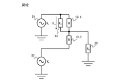
図11に示すDCリンクの正電位線における正電位Vpを、図12では等価電源51で表す。同様に、図3に示すDCリンクの負電位線における負電位Vnを、図12では等価電源52で表す。このとき、図11に示す分圧抵抗13-1及び13-2、測定用抵抗14、並びにモータ3の絶縁抵抗20は、等価電源51及び52に対して図12に示すように接続される。分圧抵抗13-1及び13-2の抵抗値をそれぞれRとし、測定用抵抗14の抵抗値をRinとし、モータ3の絶縁抵抗20の抵抗値をRmとする。抵抗電圧測定部15により測定される測定用抵抗14の抵抗電圧の値をVinとする。
図12に示す等価回路において、等価電源51及び52並びに分圧抵抗13-1及び13-2にテブナンの定理を適用すると、図13に示すような等価回路が得られる。図5において、等価電源54の電圧値V6は式12で表され、等価抵抗41の抵抗値はR/2となる。

図13に示す等価回路において、回路部分T3にテブナンの定理を適用すると、図14に示すような等価回路が得られる。図14において、等価電源55の電圧値V7は式13で表され、等価抵抗42の抵抗値R2は式14で表される。


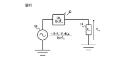
図14に示す等価回路において、等価電源53と等価電源55とは、等価抵抗42及び測定用抵抗14を介して直列に接続されているので、等価電源53と等価電源55とを1つにまとめると、図15に示すような等価電源56が得られる。図15において、等価電源56の電圧値V8は式15で表される。

図15に示す等価回路において、等価電源56の電圧値V8を差動成分と同相成分とに分けると、図16に示すような等価電源57及び58が得られる。図16において、等価電源57の電圧値V9は差動成分であり、式16で表される。等価電源58の電圧値V10は同相成分であり、式17で表される。


図16に示す等価回路は、図17に示す直流成分の等価回路と図18に示す交流成分の等価回路とに分けることができる。
図17に示すように直流成分の等価回路では、差動成分V9を有する等価電源57に等価抵抗42及び測定用抵抗14が接続される。オームの法則を用いて測定用抵抗14に印加される電圧成分VinLを求めると、式18のように表される。式18において、直流成分を含まない信号成分である(Vp+Vn)/2をVcom、直流成分を含む信号成分(Vp-Vn)/2をVdifに置き換えている。電圧成分VinLは、抵抗電圧測定部15により測定された測定用抵抗14の抵抗電圧から直流成分抽出部16(ローパスフィルタ)により交流成分を除去することで得られる直流成分に対応する。

図18に示すように交流成分の等価回路では、同相成分V10を有する等価電源58に等価抵抗42及び測定用抵抗14が接続される。オームの法則を用いて測定用抵抗14に印加される電圧成分VinHを求めると、式19のように表される。式19において、直流成分を含まない信号成分である(Vp+Vn)/2をVcom、直流成分を含む信号成分(Vp-Vn)/2をVdifに置き換えている。電圧成分VinHは、抵抗電圧測定部15により測定された測定用抵抗14の抵抗電圧から交流成分抽出部17(ハイパスフィルタ)により直流成分を除去することで得られる交流成分に対応する。

式18及び式19についての連立方程式を絶縁抵抗値Rmについて解くことで、絶縁抵抗値Rmを求めるための式11が得られる。測定用抵抗14の一端がDCリンクの正電位線に接続される第2の形態では、絶縁抵抗値計算部19は、式11に従って、モータ3の絶縁抵抗値Rmを計算する。式11において、値Vcomは(Vp+Vn)/2によって表され、値Vdifは(Vp-Vn)/2によって表される。Vpは、インバータ部12による電力変換動作の停止時にDCリンク電位測定部18により測定されるDCリンクの正電位線における正電位である。Vnは、インバータ部12による電力変換動作の停止時にDCリンク電位測定部18により測定されるDCリンクの負電位線における負電位である。直流成分VinLは、インバータ部12による電力変換動作の停止時に抵抗電圧測定部15により測定された測定用抵抗14の抵抗電圧から直流成分抽出部16(ローパスフィルタ)により交流成分を除去することで得られる。交流成分VinHは、インバータ部12による電力変換動作の停止時に抵抗電圧測定部15により測定された測定用抵抗14の抵抗電圧から交流成分抽出部17(ハイパスフィルタ)により直流成分を除去することで得られる。測定用抵抗14の抵抗値Rinについては、予め測定しておくか、あるいは、規格表に規定された値を用いればよい。また、分圧抵抗13-1及び13-2の各抵抗値Rは、式18及び式19の連立方程式を解くことによって求めることができる。つまり、「式11に従ってモータ3の絶縁抵抗値Rmを計算する」とは、「直流成分抽出部16により抽出された抵抗電圧の直流成分VinLと、交流成分抽出部17により抽出された抵抗電圧の交流成分VinHと、DCリンク電位測定部18により測定されたDCリンクの正電位Vp及び負電位Vnとに基づいて、モータ3の絶縁抵抗値Rmを計算する」ことを意味する。
なお、第2の形態において、値Vcom及び交流成分VinH並びに値Vdif及び直流成分VinLについては、整流回路を通して直流に変換してから測定してもよい。この場合、例えば交流成分抽出部17により抽出された抵抗電圧の交流成分VinHを整流したうえで絶対値をとり、この値に基づいて式20により抽出された抵抗電圧の交流成分VinHを整流したうえで絶対値をとるとともに直流成分抽出部16により抽出された抵抗電圧の直流成分VinLを整流したうえで絶対値をとり、これらの値に基づいて式20に従ってモータ3の絶縁抵抗値Rmを計算する。なお、式19の交流成分VinH及び式18の直流成分VinLの絶対値をとっているので、式20は、式11とは符号が一部異なったものとなる。

上述のように、第1の形態及び第2の形態のいずれにおいても、抵抗電圧測定部15による測定処理及びDCリンク電位測定部18による測定処理は、インバータ部12による電力変換動作を停止させた状態(すなわちインバータ部12内の全てのスイッチング素子をオフさせた状態)で実行され、このとき測定されたデータに基づいて絶縁抵抗値計算部19は絶縁抵抗値Rmを算出している。すなわち、本開示の一実施形態によれば、インバータ部12による電力変換動作を停止させた状態で、抵抗電圧測定部15、直流成分抽出部16、交流成分抽出部17、DCリンク電位測定部18、及び絶縁抵抗値計算部19を動作させることで、モータ3の絶縁抵抗値Rmを測定することができる。よって、モータ3の絶縁抵抗値Rmの測定に際して、従来のようにモータ駆動装置1を交流電源2から切り離す必要はない。また、モータ3の絶縁抵抗値Rmの測定のためにモータ駆動装置1と交流電源2との間に遮断器を設置する必要はないので、低コストである。モータ駆動装置1と交流電源2との間に遮断器が設置されない状況においても、モータ3の絶縁抵抗値Rmを測定することができる。
絶縁抵抗値計算部19により算出された絶縁抵抗値Rmを、例えば表示部(図示せず)に表示させてもよい。これにより、作業者は、モータ3の絶縁抵抗値Rmを迅速かつ容易に把握することができる。
また、絶縁抵抗値計算部19により算出された絶縁抵抗値Rmを絶縁劣化の判断基準となる閾値と比較してモータ3の絶縁劣化判定を行う判定部(図示せず)を設け、判定部により絶縁抵抗値Rmが閾値を超えたと判定した場合に、「モータ3に絶縁劣化が発生したこと」を表示部に表示させてもよい。表示部の例としては、単体のディスプレイ装置、モータ駆動装置1に付属のディスプレイ装置、並びに、パソコン及び携帯端末に付属のディスプレイ装置などがある。またあるいは、表示部とともにあるいは表示部に代えて、例えば音声、スピーカ、ブザー、チャイムなどのような音を発する音響機器にて、「モータ3に絶縁劣化が発生したこと」を作業者に通知するようにしてもよい。これにより、作業者は、モータ3に絶縁劣化が発生したことを迅速かつ容易に把握することができる。よって、作業者は、例えばモータ3の交換または修理といった対応をとること容易となる。
直流成分抽出部16、交流成分抽出部17、絶縁抵抗値計算部19、及び上位制御装置は、アナログ回路と演算処理装置との組み合わせで構成されてもよく、あるいは演算処理装置のみで構成されてもよく、あるいはアナログ回路のみで構成されてもよい。例えば、直流成分抽出部16、交流成分抽出部17、絶縁抵抗値計算部19、及び上位制御装置をソフトウェアプログラム形式で構築する場合は、演算処理装置をこのソフトウェアプログラムに従って動作させることで、直流成分抽出部16、交流成分抽出部17、絶縁抵抗値計算部19、及び上位制御装置の各機能を実現することができる。またあるいは、直流成分抽出部16、交流成分抽出部17、絶縁抵抗値計算部19、及び上位制御装置を、各部の機能を実現するソフトウェアプログラムを書き込んだ半導体集積回路として実現してもよい。またあるいは、直流成分抽出部16、交流成分抽出部17、絶縁抵抗値計算部19、及び上位制御装置を、各部の機能を実現するソフトウェアプログラムを書き込んだ記録媒体として実現してもよい。また、直流成分抽出部16、交流成分抽出部17、絶縁抵抗値計算部19、及び上位制御装置は、例えば工作機械の数値制御装置内に設けられてもよく、ロボットを制御するロボットコントローラ内に設けられてもよい。
抵抗電圧測定部15及びDCリンク電位測定部18は、アナログ回路と演算処理装置との組み合わせで構成されてもよく、あるいは演算処理装置のみで構成されてもよく、あるいはアナログ回路のみで構成されてもよい。抵抗電圧測定部15及びDCリンク電位測定部18については、モータ駆動装置1に一般的に設けられるものを流用してもよい。ただし、絶縁抵抗値計算部19による絶縁抵抗値Rmの算出には、インバータ部12による電力変換動作を停止させた状態において抵抗電圧測定部15及びDCリンク電位測定部18により測定されたデータが用いられる。
図19は、本開示の一実施形態によるモータ駆動装置の動作フローを示すフローチャートである。図19に示すフローチャートは、第1の形態及び第2の形態のいずれのモータ駆動装置1についても適用可能である。
モータ3の絶縁抵抗値Rmを測定するに際し、まず、ステップS101において、上位制御装置(図示せず)は、インバータ部12内の全てのスイッチング素子をオフさせてインバータ部12による電力変換動作を停止させる。
ステップS102において、抵抗電圧測定部15は、測定用抵抗14の両端の電位差である抵抗電圧Vinを測定する。抵抗電圧測定部15により測定された測定用抵抗14の抵抗電圧Vinに関する信号は、直流成分抽出部16及び交流成分抽出部17へ送られる。
ステップS103において、直流成分抽出部16は、抵抗電圧測定部15により測定された抵抗電圧Vinから直流成分VinLを抽出する。直流成分抽出部16により抽出された抵抗電圧の直流成分VinLに関する信号は、絶縁抵抗値計算部19へ送られる。
ステップS104において、交流成分抽出部17は、抵抗電圧測定部15により測定された抵抗電圧Vinから交流成分VinHを抽出する。交流成分抽出部17により抽出された抵抗電圧の交流成分VinHに関する信号は、絶縁抵抗値計算部19へ送られる。
なお、ステップS103の処理とステップS104の処理とは順序を入れ替えて実行してもよい。
ステップS105において、DCリンク電位測定部18は、DCリンクの正電位線における正電位Vp及び負電位線における負電位Vnを測定する。DCリンク電位測定部18により測定されたDCリンクの正電位Vp及び負電位Vnに関する信号は、絶縁抵抗値計算部19へ送られる。
なお、ステップS102~S104の処理とステップS105の処理とは順序を入れ替えて実行してもよい。
ステップS106において、絶縁抵抗値計算部19は、直流成分抽出部16により抽出された抵抗電圧の直流成分VinLと、交流成分抽出部17により抽出された抵抗電圧の交流成分VinHと、DCリンク電位測定部18により測定されたDCリンクの正電位Vp及び負電位Vnとに基づいて、モータ3の絶縁抵抗値Rmを計算する。測定用抵抗14の一端がDCリンクの負電位線に接続される第1の形態では、絶縁抵抗値計算部19は、式1に従ってモータ3の絶縁抵抗値Rmを計算する。測定用抵抗14の一端がDCリンクの正電位線に接続される第2の形態では、絶縁抵抗値計算部19は、式11に従ってモータ3の絶縁抵抗値Rmを計算する。
ステップS106の後、例えば、絶縁抵抗値計算部19により算出された絶縁抵抗値Rmを、表示部(図示せず)に表示させてもよい。また例えば、絶縁抵抗値計算部19により算出された絶縁抵抗値Rmを絶縁劣化の判断基準となる閾値と比較してモータ3の絶縁劣化判定を行う判定部(図示せず)を設け、判定部により絶縁抵抗値Rmが閾値を超えたと判定した場合に、「モータ3に絶縁劣化が発生したこと」を表示部に表示させてもよい。また例えば、表示部とともにあるいは表示部に代えて、例えば音声、スピーカ、ブザー、チャイムなどのような音を発する音響機器にて、「モータ3に絶縁劣化が発生したこと」を作業者に通知するようにしてもよい。
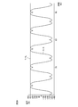
図20は、デルタ結線により交流電源と本開示の一実施形態によるモータ駆動装置とが結線される場合におけるDCリンクの正電位及び負電位のシミュレーション結果を説明する図である。式1及び式11に示したように、絶縁抵抗値Rmの計算にあたっては(Vp+Vn)/2で表される値Vcomと(Vp-Vn)/2で表されるVdifを用いている。図20に示すように、正電位Vpと負電位Vnの差「Vp-Vn」が一定であることから直流成分として機能しており、正電位Vpと負電位Vnの和「Vp+Vn」が一定であることから交流成分として機能していることが分かる。
1 モータ駆動装置
2 交流電源
3 モータ
4 DCリンクコンデンサ
11 コンバータ部
12 インバータ部
13-1、13-2 分圧抵抗
14 測定用抵抗
15 抵抗電圧測定部
16 直流成分抽出部
17 交流成分抽出部
18 DCリンク電位測定部
19 絶縁抵抗値計算部
20 モータの絶縁抵抗
21、22 等価抵抗
31、32、33、34、35、36、37、38 等価電源
41、42 等価抵抗
51、52、53、54、55、56、57、58 等価電源
2 交流電源
3 モータ
4 DCリンクコンデンサ
11 コンバータ部
12 インバータ部
13-1、13-2 分圧抵抗
14 測定用抵抗
15 抵抗電圧測定部
16 直流成分抽出部
17 交流成分抽出部
18 DCリンク電位測定部
19 絶縁抵抗値計算部
20 モータの絶縁抵抗
21、22 等価抵抗
31、32、33、34、35、36、37、38 等価電源
41、42 等価抵抗
51、52、53、54、55、56、57、58 等価電源
Claims (5)
- 交流電源から入力された交流電力を直流電力に変換してDCリンクへ出力するコンバータ部と、
前記DCリンクに設けられるDCリンクコンデンサと、
前記DCリンクにおける直流電力をモータの駆動のための交流電力に変換して出力するインバータ部と、
前記DCリンクを構成する正電位線と負電位線との間に設けられる互いに直列接続された2つの分圧抵抗であって、前記分圧抵抗どうしの接続点と前記モータの巻線とが接続される分圧抵抗と、
前記分圧抵抗どうしの前記接続点と前記DCリンクの前記正電位線または前記負電位線との間に接続される測定用抵抗と、
前記測定用抵抗の両端の電位差である抵抗電圧を測定する抵抗電圧測定部と、
前記抵抗電圧測定部により測定された前記抵抗電圧から直流成分を抽出する直流成分抽出部と、
前記抵抗電圧測定部により測定された前記抵抗電圧から交流成分を抽出する交流成分抽出部と、
前記DCリンクの前記正電位線における前記正電位及び前記負電位線における負電位を測定するDCリンク電位測定部と、
前記直流成分抽出部により抽出された前記直流成分と、前記交流成分抽出部により抽出された前記交流成分と、前記DCリンク電位測定部により測定された前記正電位及び前記負電位と、に基づいて、前記モータの絶縁抵抗値を計算する絶縁抵抗値計算部と、
を備える、モータ駆動装置。 - 前記測定用抵抗は、前記分圧抵抗どうしの前記接続点と前記DCリンクの前記負電位線との間に接続され、
前記絶縁抵抗値計算部は、前記測定用抵抗の抵抗値をRin、前記DCリンク電位測定部により測定された前記正電位の値をVp、前記DCリンク電位測定部により測定された前記負電位の値をVn、前記直流成分抽出部により抽出された前記直流成分の値をVinL、前記交流成分抽出部により抽出された前記交流成分の値をVinH、値Vcomを(Vp+Vn)/2、値Vdifを(Vp-Vn)/2としたとき、

- 前記測定用抵抗は、前記分圧抵抗どうしの前記接続点と前記DCリンクの前記正電位線との間に接続され、
前記絶縁抵抗値計算部は、前記測定用抵抗の抵抗値をRin、前記DCリンク電位測定部により測定された前記正電位の値をVp、前記DCリンク電位測定部により測定された前記負電位の値をVn、前記直流成分抽出部により抽出された前記直流成分の値をVinL、前記交流成分抽出部により抽出された前記交流成分の値をVinH、値Vcomを(Vp+Vn)/2、値Vdifを(Vp-Vn)/2としたとき、

- 前記分圧抵抗の各々は、前記DCリンクの前記正電位線と前記負電位線との間に接続される互いに直列接続された2つのDCリンク抵抗の各々にて構成される、請求項1~3のいずれか一項に記載のモータ駆動装置。
- 前記分圧抵抗の各々は、前記インバータ部内のブリッジ回路を構成する上アーム及び下アームのそれぞれに設けられるスイッチング素子のオフ時に発生するオフ抵抗の各々にて構成される、請求項1~3のいずれか一項に記載のモータ駆動装置。
Priority Applications (4)
| Application Number | Priority Date | Filing Date | Title |
|---|---|---|---|
| DE112021002712.3T DE112021002712T5 (de) | 2020-07-06 | 2021-06-29 | Motoransteuerungsvorrichtung, die einen isolationswiderstandswert eines motors berechnet |
| JP2022535261A JP7381756B2 (ja) | 2020-07-06 | 2021-06-29 | モータの絶縁抵抗値を計算するモータ駆動装置 |
| US17/918,611 US20230143105A1 (en) | 2020-07-06 | 2021-06-29 | Motor drive device that calculates insulation resistance value of motor |
| CN202180047729.2A CN115769485B (zh) | 2020-07-06 | 2021-06-29 | 计算电动机的绝缘电阻值的电动机驱动装置 |
Applications Claiming Priority (2)
| Application Number | Priority Date | Filing Date | Title |
|---|---|---|---|
| JP2020116538 | 2020-07-06 | ||
| JP2020-116538 | 2020-07-06 |
Publications (1)
| Publication Number | Publication Date |
|---|---|
| WO2022009740A1 true WO2022009740A1 (ja) | 2022-01-13 |
Family
ID=79553095
Family Applications (1)
| Application Number | Title | Priority Date | Filing Date |
|---|---|---|---|
| PCT/JP2021/024604 Ceased WO2022009740A1 (ja) | 2020-07-06 | 2021-06-29 | モータの絶縁抵抗値を計算するモータ駆動装置 |
Country Status (5)
| Country | Link |
|---|---|
| US (1) | US20230143105A1 (ja) |
| JP (1) | JP7381756B2 (ja) |
| CN (1) | CN115769485B (ja) |
| DE (1) | DE112021002712T5 (ja) |
| WO (1) | WO2022009740A1 (ja) |
Cited By (1)
| Publication number | Priority date | Publication date | Assignee | Title |
|---|---|---|---|---|
| WO2026033716A1 (ja) * | 2024-08-08 | 2026-02-12 | ファナック株式会社 | モータの絶縁抵抗値を計算するモータ駆動装置 |
Families Citing this family (1)
| Publication number | Priority date | Publication date | Assignee | Title |
|---|---|---|---|---|
| US12480996B2 (en) * | 2023-08-07 | 2025-11-25 | Garrett Transportation I Inc. | System and method for e-machine stator insulation resistance monitoring |
Citations (4)
| Publication number | Priority date | Publication date | Assignee | Title |
|---|---|---|---|---|
| JP2008102096A (ja) * | 2006-10-20 | 2008-05-01 | Fanuc Ltd | モータの絶縁抵抗劣化検出装置 |
| WO2013018411A1 (ja) * | 2011-07-29 | 2013-02-07 | 三洋電機株式会社 | モータ駆動回路、モータ装置、および移動体 |
| JP2020058209A (ja) * | 2018-10-04 | 2020-04-09 | ファナック株式会社 | モータ駆動装置 |
| JP2020080623A (ja) * | 2018-11-13 | 2020-05-28 | ファナック株式会社 | ダイナミックブレーキ回路を有するモータ駆動装置及びモータ駆動システム |
Family Cites Families (8)
| Publication number | Priority date | Publication date | Assignee | Title |
|---|---|---|---|---|
| JP2002311080A (ja) | 2001-04-13 | 2002-10-23 | Kawasaki Steel Corp | 電動機の絶縁劣化検出装置 |
| JP2008157672A (ja) * | 2006-12-21 | 2008-07-10 | Fanuc Ltd | モータの絶縁劣化検出装置 |
| EP2256506B1 (de) * | 2009-05-27 | 2019-07-03 | Bender GmbH & Co. KG | Verfahren und Vorrichtung zur Isolationsüberwachung von ungeerdeten Gleich- und Wechselspannungsnetzen |
| JP5442078B2 (ja) * | 2012-08-02 | 2014-03-12 | 山洋電気株式会社 | モータ制御装置及びモータの絶縁劣化検出方法 |
| WO2015075821A1 (ja) * | 2013-11-22 | 2015-05-28 | 三菱電機株式会社 | 絶縁検出器及び電気機器 |
| JP5788538B2 (ja) * | 2014-01-08 | 2015-09-30 | ファナック株式会社 | 絶縁劣化検出機能を備えたモータ駆動装置及びモータの絶縁抵抗検出方法 |
| JP6407931B2 (ja) * | 2016-09-28 | 2018-10-17 | ファナック株式会社 | 絶縁抵抗検出機能を備えたモータ駆動装置 |
| JP7489293B2 (ja) * | 2020-11-02 | 2024-05-23 | オークマ株式会社 | モータ絶縁検査機能付きインバータ装置 |
-
2021
- 2021-06-29 US US17/918,611 patent/US20230143105A1/en not_active Abandoned
- 2021-06-29 CN CN202180047729.2A patent/CN115769485B/zh active Active
- 2021-06-29 DE DE112021002712.3T patent/DE112021002712T5/de active Pending
- 2021-06-29 WO PCT/JP2021/024604 patent/WO2022009740A1/ja not_active Ceased
- 2021-06-29 JP JP2022535261A patent/JP7381756B2/ja active Active
Patent Citations (4)
| Publication number | Priority date | Publication date | Assignee | Title |
|---|---|---|---|---|
| JP2008102096A (ja) * | 2006-10-20 | 2008-05-01 | Fanuc Ltd | モータの絶縁抵抗劣化検出装置 |
| WO2013018411A1 (ja) * | 2011-07-29 | 2013-02-07 | 三洋電機株式会社 | モータ駆動回路、モータ装置、および移動体 |
| JP2020058209A (ja) * | 2018-10-04 | 2020-04-09 | ファナック株式会社 | モータ駆動装置 |
| JP2020080623A (ja) * | 2018-11-13 | 2020-05-28 | ファナック株式会社 | ダイナミックブレーキ回路を有するモータ駆動装置及びモータ駆動システム |
Cited By (1)
| Publication number | Priority date | Publication date | Assignee | Title |
|---|---|---|---|---|
| WO2026033716A1 (ja) * | 2024-08-08 | 2026-02-12 | ファナック株式会社 | モータの絶縁抵抗値を計算するモータ駆動装置 |
Also Published As
| Publication number | Publication date |
|---|---|
| US20230143105A1 (en) | 2023-05-11 |
| JP7381756B2 (ja) | 2023-11-15 |
| CN115769485B (zh) | 2025-12-23 |
| JPWO2022009740A1 (ja) | 2022-01-13 |
| DE112021002712T5 (de) | 2023-02-23 |
| CN115769485A (zh) | 2023-03-07 |
Similar Documents
| Publication | Publication Date | Title |
|---|---|---|
| JP5606387B2 (ja) | モータ制御装置及びモータの絶縁劣化検出方法 | |
| JP3218954B2 (ja) | 交流モータ制御回路の異常検出装置 | |
| JP5024827B2 (ja) | インバータ装置 | |
| JP6694006B2 (ja) | Dcリンクコンデンサの短絡判定部を有するモータ駆動装置 | |
| CN104113258B (zh) | 具备dc链路部异常检测功能的电动机驱动装置 | |
| JP2012233826A5 (ja) | ||
| JP6629893B2 (ja) | 浮遊容量を推定するモータ駆動装置 | |
| CN108604876B (zh) | 电动机控制装置 | |
| CN107800333B (zh) | 电动机控制装置 | |
| KR20150122069A (ko) | 전동기 구동 장치 | |
| CN115485945B (zh) | 检测并联驱动的开关的故障的故障检测装置及电动机驱动装置 | |
| CN112219348A (zh) | 转换器及电动机控制装置 | |
| US9641120B2 (en) | Motor control apparatus and method for controlling motor | |
| CN106961230A (zh) | 电动机控制装置 | |
| CN101385236A (zh) | 接地故障检测方法 | |
| JP7381756B2 (ja) | モータの絶縁抵抗値を計算するモータ駆動装置 | |
| WO2018078837A1 (ja) | 電動機駆動装置 | |
| JP5300349B2 (ja) | モータ制御装置およびモータ地絡検出方法 | |
| US20090052209A1 (en) | Inverter Device | |
| JP3900358B2 (ja) | 電気車制御装置 | |
| JP5959349B2 (ja) | 電気車制御装置および車両駆動システム | |
| JP2002233180A (ja) | 電力変換装置 | |
| CN115208273B (zh) | 电力转换装置以及电动机控制方法 | |
| JP6975060B2 (ja) | 浮遊容量を推定するモータ駆動装置 | |
| KR101393574B1 (ko) | 모터의 전력 케이블의 단선 검출 방법 및 모터 제어 방법 |
Legal Events
| Date | Code | Title | Description |
|---|---|---|---|
| 121 | Ep: the epo has been informed by wipo that ep was designated in this application |
Ref document number: 21837850 Country of ref document: EP Kind code of ref document: A1 |
|
| ENP | Entry into the national phase |
Ref document number: 2022535261 Country of ref document: JP Kind code of ref document: A |
|
| 122 | Ep: pct application non-entry in european phase |
Ref document number: 21837850 Country of ref document: EP Kind code of ref document: A1 |