WO2022009684A1 - 再多重装置、放送システム、再多重方法、及びプログラムが格納された非一時的なコンピュータ可読媒体 - Google Patents
再多重装置、放送システム、再多重方法、及びプログラムが格納された非一時的なコンピュータ可読媒体 Download PDFInfo
- Publication number
- WO2022009684A1 WO2022009684A1 PCT/JP2021/023861 JP2021023861W WO2022009684A1 WO 2022009684 A1 WO2022009684 A1 WO 2022009684A1 JP 2021023861 W JP2021023861 W JP 2021023861W WO 2022009684 A1 WO2022009684 A1 WO 2022009684A1
- Authority
- WO
- WIPO (PCT)
- Prior art keywords
- remultiplexing
- packet
- resolution
- broadcast data
- data
- Prior art date
- Legal status (The legal status is an assumption and is not a legal conclusion. Google has not performed a legal analysis and makes no representation as to the accuracy of the status listed.)
- Ceased
Links
Images



Classifications
-
- H—ELECTRICITY
- H04—ELECTRIC COMMUNICATION TECHNIQUE
- H04N—PICTORIAL COMMUNICATION, e.g. TELEVISION
- H04N21/00—Selective content distribution, e.g. interactive television or video on demand [VOD]
- H04N21/20—Servers specifically adapted for the distribution of content, e.g. VOD servers; Operations thereof
- H04N21/23—Processing of content or additional data; Elementary server operations; Server middleware
- H04N21/236—Assembling of a multiplex stream, e.g. transport stream, by combining a video stream with other content or additional data, e.g. inserting a URL [Uniform Resource Locator] into a video stream, multiplexing software data into a video stream; Remultiplexing of multiplex streams; Insertion of stuffing bits into the multiplex stream, e.g. to obtain a constant bit-rate; Assembling of a packetised elementary stream
- H04N21/23608—Remultiplexing multiplex streams, e.g. involving modifying time stamps or remapping the packet identifiers
-
- H—ELECTRICITY
- H04—ELECTRIC COMMUNICATION TECHNIQUE
- H04H—BROADCAST COMMUNICATION
- H04H20/00—Arrangements for broadcast or for distribution combined with broadcast
- H04H20/28—Arrangements for simultaneous broadcast of plural pieces of information
-
- H—ELECTRICITY
- H04—ELECTRIC COMMUNICATION TECHNIQUE
- H04H—BROADCAST COMMUNICATION
- H04H20/00—Arrangements for broadcast or for distribution combined with broadcast
- H04H20/44—Arrangements characterised by circuits or components specially adapted for broadcast
-
- H—ELECTRICITY
- H04—ELECTRIC COMMUNICATION TECHNIQUE
- H04N—PICTORIAL COMMUNICATION, e.g. TELEVISION
- H04N21/00—Selective content distribution, e.g. interactive television or video on demand [VOD]
- H04N21/20—Servers specifically adapted for the distribution of content, e.g. VOD servers; Operations thereof
- H04N21/23—Processing of content or additional data; Elementary server operations; Server middleware
- H04N21/236—Assembling of a multiplex stream, e.g. transport stream, by combining a video stream with other content or additional data, e.g. inserting a URL [Uniform Resource Locator] into a video stream, multiplexing software data into a video stream; Remultiplexing of multiplex streams; Insertion of stuffing bits into the multiplex stream, e.g. to obtain a constant bit-rate; Assembling of a packetised elementary stream
- H04N21/2362—Generation or processing of Service Information [SI]
-
- H—ELECTRICITY
- H04—ELECTRIC COMMUNICATION TECHNIQUE
- H04N—PICTORIAL COMMUNICATION, e.g. TELEVISION
- H04N21/00—Selective content distribution, e.g. interactive television or video on demand [VOD]
- H04N21/20—Servers specifically adapted for the distribution of content, e.g. VOD servers; Operations thereof
- H04N21/23—Processing of content or additional data; Elementary server operations; Server middleware
- H04N21/242—Synchronisation processes, e.g. processing of PCR [Programme Clock References]
-
- H—ELECTRICITY
- H04—ELECTRIC COMMUNICATION TECHNIQUE
- H04N—PICTORIAL COMMUNICATION, e.g. TELEVISION
- H04N21/00—Selective content distribution, e.g. interactive television or video on demand [VOD]
- H04N21/60—Network structure or processes for video distribution between server and client or between remote clients; Control signalling between clients, server and network components; Transmission of management data between server and client, e.g. sending from server to client commands for recording incoming content stream; Communication details between server and client
- H04N21/61—Network physical structure; Signal processing
- H04N21/6106—Network physical structure; Signal processing specially adapted to the downstream path of the transmission network
- H04N21/6112—Network physical structure; Signal processing specially adapted to the downstream path of the transmission network involving terrestrial transmission, e.g. DVB-T
Definitions
- the present invention relates to a remultiplexing device, a broadcasting system, a remultiplexing method, and a program.
- ARIB STD-B31 which is a standard for 2K broadcasting, generally indicates dependent synchronization and reference synchronization as the synchronization method of SFN (Single Frequency Network), but the ones actually operated are almost dependent synchronization. Is.
- 4K broadcasting by satellite was commercialized in advance.
- a line different from the line used in 2K broadcasting is used for data transmission from the performance station to the transmission station.
- an IP (Internet Protocol) network is used instead of the existing line that transmits MPEG-2 TS (Transport Stream).
- the existing line that transmits TS has a fixed delay time due to transmission, but in an IP network, the delay time due to transmission fluctuates by a certain amount due to fluctuations in the transfer path or load. For this reason, when transmitting data for 4K broadcasting over an IP network while transmitting data for 2K broadcasting from a performance station to a transmission station via an existing transmission line for 2K broadcasting, an existing fixed delay is used. SFN synchronization cannot be achieved due to dependent synchronization.
- the technique disclosed in Patent Document 1 is known.
- the output timing is determined by specifying the frame start timing using an absolute reference time (NTP (Network Time Protocol) information or the like).
- NTP Network Time Protocol
- Patent Document 1 The synchronization method described in Patent Document 1 is a reference synchronization using an absolute reference time, and it is not easy to apply it to an existing system that performs dependent synchronization.
- the present disclosure has been made to solve such a problem, and it is possible to realize synchronization of outputs when broadcasting the broadcast data of the first resolution and the broadcast data of the second resolution. It is an object of the present invention to provide a multiplexing device, a broadcasting system, a remultiplexing method, and a program.
- the remultiplexing device is In order to output the broadcast data of the first resolution as an OFDM (Orthogonal Frequency Division Multiplexing) modulated wave from one or more transmitters, the input broadcast data of the first resolution is remultiplexed and remultiplexed.
- a first remultiplexing means for outputting the first transmission data generated by the processing to the transmission device via the first line, and In order to output the broadcast data of the second resolution together with the broadcast data of the first resolution as the OFDM modulated wave from the transmission device, the input broadcast data of the second resolution is remultiplexed and the said.
- a second remultiplexing means for outputting the second transmission data generated by the remultiplexing process to the transmission device via the second line, and Have,
- the second remultiplexing means sets a difference in delay time between the first line and the second line at a timing corresponding to the timing of the first packet of the OFDM frame set by the first remultiplexing means.
- Insert a delay control packet which is a packet containing control information for compensation
- the second remultiplexing means generates, as the control information, an index value of a waiting time from the time when the delay control packet is received in the transmission device to the start of the modulation process for the packet following the delay control packet. do.
- the broadcasting system is With the remultiplexing device, One or more transmitters that output the data received from the remultiplexer as OFDM modulated waves, and Equipped with The remultiplexing device In order to output the broadcast data of the first resolution as an OFDM modulated wave from the transmission device, the input broadcast data of the first resolution is remultiplexed, and the first remultiplexing process is generated.
- a first remultiplexing means for outputting transmission data to the transmission device via the first line, and In order to output the broadcast data of the second resolution together with the broadcast data of the first resolution as the OFDM modulated wave from the transmission device, the input broadcast data of the second resolution is remultiplexed and the said.
- a second remultiplexing means for outputting the second transmission data generated by the remultiplexing process to the transmission device via the second line, and Have,
- the second remultiplexing means sets a difference in delay time between the first line and the second line at a timing corresponding to the timing of the first packet of the OFDM frame set by the first remultiplexing means.
- Insert a delay control packet which is a packet containing control information for compensation
- the second remultiplexing means generates, as the control information, an index value of a waiting time from the time when the delay control packet is received in the transmission device to the start of the modulation process for the packet following the delay control packet.
- the transmitter is A delay correction means for adjusting the timing of starting the modulation process for the packet following the delay control packet based on the control information. It has a modulation processing means that modulates the broadcast data of the first resolution and the broadcast data of the second resolution and outputs them as OFDM modulated waves.
- the input broadcast data of the first resolution is remultiplexed, and the first is generated by the remultiplexing process.
- the transmission data of 1 is output to the transmission device via the first line, and the transmission data is output to the transmission device.
- the input broadcast data of the second resolution is remultiplexed and the said.
- the second transmission data generated by the remultiplexing process is output to the transmission device via the second line.
- a delay control packet which is a packet containing control information for compensating for the difference in delay time between the first line and the second line, is generated.
- the delay control packet is inserted at a timing corresponding to the timing of the first packet of the OFDM frame set in the remultiplexing process for the broadcast data of the first resolution.
- the index value of the waiting time from the time when the delay control packet is received in the transmission device to the start of the modulation processing for the packet following the delay control packet is generated as the control information. ..
- the program according to the fourth aspect of the present disclosure is In order to output the broadcast data of the first resolution as an OFDM modulated wave from one or more transmission devices, the input broadcast data of the first resolution is remultiplexed, and the first is generated by the remultiplexing process.
- the first remultiplexing step of outputting the transmission data of 1 to the transmission device via the first line, and
- the input broadcast data of the second resolution is remultiplexed and the said.
- a second remultiplexing step of outputting the second transmission data generated by the remultiplexing process to the transmission device via the second line Let the computer run In the second remultiplexing step, the difference in delay time between the first line and the second line is set at a timing corresponding to the timing of the first packet of the OFDM frame set in the first remultiplexing step. Insert a delay control packet, which is a packet containing control information for compensation, In the second remultiplexing step, an index value of the waiting time from the time when the delay control packet is received in the transmission device to the start of the modulation processing for the packet following the delay control packet is generated as the control information. do.
- a remultiplexing device capable of realizing synchronization of outputs when broadcasting broadcast data of a first resolution and broadcast data of a second resolution are provided. Can be provided.
- FIG. It is a schematic diagram which shows an example of the structure of the broadcasting system which concerns on Embodiment 1.
- FIG. It is a block diagram which shows an example of the structure of the remultiplexing apparatus which concerns on Embodiment 1.
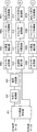
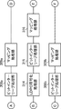
- FIG. It is a block diagram which shows an example of the structure of a modulation part. It is a block diagram which shows an example of the structure of a modulation part. It is a block diagram which shows an example of the structure of a modulation part.
- FIG. 1 is a schematic diagram showing an example of the configuration of the broadcasting system 10 according to the first embodiment.
- the broadcasting system 10 includes a remultiplexing device 20 and one or more transmitting devices 30.
- the remultiplexing device 20 is a device installed in a performance hall
- the transmitting device 30 is a device installed in a transmitting station.
- broadcast data is transmitted from the remultiplexing device 20 to the transmitting device 30, and the transmitting device 30 outputs a broadcast wave.
- the broadcasting system 10 is a system that broadcasts by a single frequency network (SFN).
- SFN single frequency network
- one or more transmitters 30 output broadcast waves using the same frequency band.
- the broadcasting system 10 outputs a signal for 2K broadcasting and a signal for 4K broadcasting from the transmission device 30 using the same frequency band.
- the broadcasting system 10 realizes SFN synchronization without using a reference signal such as a PPS (Pulse Per Second) signal of a GPS (Global Positioning System). That is, the broadcasting system 10 is a broadcasting system that performs subordinate synchronization, not reference synchronization.
- 2K is a general term for images whose screen resolution is full high-definition. That is, 2K is a general term for images having a width of about 2000 and a height of about 1000.
- the 2K screen resolution is horizontal 2048 x vertical 1080, horizontal 1920 x vertical 1080, horizontal 2048 x vertical 1152, horizontal 2560 x vertical 1600, horizontal 1440 x vertical 1080, and the like.
- 4K is a general term for images whose screen resolution is four times that of full high-definition. That is, 4K is a general term for images having a screen resolution of about 4000 in width ⁇ 2000 in height.
- the 4K screen resolution is horizontal 4096 ⁇ vertical 2160, horizontal 3840 ⁇ vertical 2160, horizontal 4096 ⁇ vertical 2304, horizontal 4096 ⁇ vertical 2048, and the like.
- Broadcast data for 2K broadcasting and broadcast data for 4K broadcasting to be transmitted from the transmission device 30 using the same frequency band at the same time as the broadcasting data for 2K broadcasting are input to the remultiplexing device 20. ..
- These broadcast data are input to the remultiplexing device 20 from, for example, another device provided in the performance hall equipped with the remultiplexing device 20 via an optical line or a coaxial cable.
- the re-multiplexing device 20 performs a re-multiplexing process described later on these broadcast data, and outputs the re-multiplexed data to each transmission device 30.
- Each transmitting device 30 performs OFDM modulation on the data received from the remultiplexing device 20 by the modulation unit 300, and outputs the received data as an OFDM modulated wave.
- each transmission device 30 synchronizes the output timing from each transmission device 30 by adjusting the start timing of the modulation process. That is, each transmission device 30 realizes SFN synchronization.
- the data for 2K broadcasting is used. It is necessary to adjust the start timing of the data modulation process for 4K broadcasting.
- the remultiplexing device 20 inserts a packet for controlling this timing (hereinafter, also referred to as a timing packet or a delay control packet) into the packet sequence transmitted from the remultiplexing device 20 to the transmitting device 30.
- the data for 2K broadcasting and the data for 4K broadcasting are transmitted from the remultiplexing device 20 to each transmitting device 30 on different lines.
- the data for 2K broadcasting is transmitted by the one-to-one microwave line 40a
- the data for 4K broadcasting is transmitted by the IP network 40b.
- FIG. 1 the transmission path of data for 2K broadcasting is shown by a solid line
- the transmission path of data for 4K broadcasting is shown by a broken line.
- the data for 2K broadcasting is wirelessly transmitted from the remultiplexing device 20 to the transmitting device 30, and the data for 4K broadcasting is transmitted by wire from the remultiplexing device 20 to the transmitting device 30. Is not limited to wireless or wired.
- transmission from the remultiplexing device 20 to the transmitting device 30 by the microwave line 40a may be performed via a relay device (not shown).
- the delay time in the transmission line is constant. That is, the delay time of transmission from the remultiplexing device 20 to one transmitting device 30 is constant in the delay time A, and the delay time of transmission from the remultiplexing device 20 to another transmitting device 30 is constant in the delay time B. Is. In general, the delay time A and the delay time B are different. On the other hand, in the IP network 40b, the delay time of transmission from the remultiplexing device 20 to the transmitting device 30 varies within a certain fluctuation range. Further, in general, the delay time of transmission of 4K broadcasting data in the IP network 40b is shorter than the delay time of transmission of 2K broadcasting data by the microwave line 40a.
- FIG. 2 is a block diagram showing an example of the configuration of the remultiplexing device 20 according to the first embodiment.
- the remultiplexing device 20 mainly includes a 2K remultiplexing unit 210, a 4K remultiplexing unit 220, and a packet output unit 230.
- the 2K remultiplexing unit 210 performs remultiplexing processing on the input 2K broadcasting data in order to output the 2K broadcasting data as an OFDM modulated wave from one or more transmission devices 30.
- the first transmission data (2K transmission data) generated by the remultiplexing process is output to the transmission device 30 via the microwave line 40a.
- the 4K remultiplexing unit 220 performs remultiplexing processing on the input 4K broadcasting data in order to output the 4K broadcasting data together with the 2K broadcasting data as an OFDM modulated wave from the transmission device 30.
- the second transmission data (4K transmission data) generated by the remultiplexing process is output to the transmission device 30 via the IP network 40b.
- Data for 2K broadcasting is input to the 2K remultiplexing unit 210.
- This data is a TS packet standardized by MPEG-2.
- data for 4K broadcasting is input to the 4K remultiplexing unit 220.
- This data is, for example, a TS packet, but may be a TLV (TypeLengthValue) packet.
- the data input to the 2K remultiplexing unit 210 and the 4K remultiplexing unit 220 is, for example, data in which video and audio are multiplexed.
- the 2K remultiplexing unit 210 is a processing unit that performs a known remultiplexing process.
- the 2K remultiplexing unit 210 is a transmission device 30 based on a predetermined parameter value of a modulation parameter (for example, multi-value degree, coding rate, etc.) of the primary modulation performed on the data for 2K broadcasting in the transmission device 30. Determine the data rate to enter in.
- the 2K re-multiplexing unit 210 converts a null packet, which is a packet in which null data is stored, into a 2K re-multiplexing unit so that broadcast data is output from the 2K re-multiplexing unit 210 at a determined data rate. Insert for the data input to 210. That is, the 2K remultiplexing unit 210 outputs the transport stream (TS) at a predetermined data rate specified based on the modulation parameter.
- a modulation parameter for example, multi-value degree, coding rate, etc.
- the 2K remultiplexing unit 210 outputs a processing clock (CLK) and a frame synchronization signal (Fsync) to the transmission device 30 in addition to the transport stream including data such as video and audio. These are received by the transmitting device 30 via the microwave line 40a. Since the output of TS, CLK, and Fsync by the 2K remultiplexing unit 210 is a known technique, detailed description thereof will be omitted.
- the processing clock (CLK) is the same as the clock used in the processing of the remultiplexing device 20, and the transmitting device 30 performs processing according to the processing clock received from the remultiplexing device 20.
- the frame synchronization signal is a signal synchronized with the period of the OFDM frame (frame length of the OFDM frame), and is a signal indicating the start of a data group (packet group) constituting one OFDM frame. be.
- the period of the OFDM frame is uniquely specified by the modulation parameters (mode and guard interval) of the OFDM modulation. In this way, it can be said that the 2K remultiplexing unit 210 sets the timing of the first packet of each OFDM frame to be configured by the transmitting device 30.
- the 2K remultiplexing unit 210 multiplexes the IIP (ISDB-T Information Packet) including TMCC (Transmission and Multiplexing Configuration Control) information and the like in the TS, as in the known remultiplexing unit. More specifically, the 2K remultiplexing unit 210 multiplexes the IIP to the TS every cycle of the frame synchronization signal (Fsync), that is, every cycle of the OFDM frame.
- the TMCC information is information including parameters such as modulation parameters that define modulation in the transmission device 30.
- the TMCC information multiplexed by the 2K remultiplexing unit 210 includes TMCC_synchronization_word defined by ARIB STD-B31.
- the value of TMCC_synchronization_word is set to either the first value W0 or the second value W1.
- the 2K remultiplexing unit 210 switches the value of TMCC_synchronization_word every cycle of the frame synchronization signal (Fsync), that is, every cycle of the OFDM frame, and multiplexes the TS. Therefore, the 2K remultiplexing unit 210 alternately outputs the first value W0 and the second value W1 for each cycle of the frame synchronization signal (Fsync).
- the parameter TMCC_synchronization_word can also be said to be information indicating whether the OFDM frame composed of the data group in which the parameter is multiplexed is the odd-numbered frame or the even-numbered frame. Alternatively, it can be said to be information indicating whether the data group (packet group) in which the parameter is multiplexed is the odd-numbered data group or the even-numbered data group.
- the IIP packet includes the continuity_counter used in the MPEG-2 transport stream. Therefore, the 2K remultiplexing unit 210 multiplexes and outputs the value of continuity_counter to the TS for each cycle of the frame synchronization signal (Fsync), that is, for each cycle of the OFDM frame.
- the continuity_counter is a parameter for sequentially counting the transmitted TS packets, and is a parameter included in the TS packet.
- the value of the continuity_counter of the first TS packet in the TS packet group in which the IIP packet is multiplexed is stored.
- the value of continuity_counter included in the IIP packet output by the 2K remultiplexing unit 210 for each cycle of the frame synchronization signal (Fsync) will fluctuate for each cycle of the frame synchronization signal (Fsync).
- the 2K remultiplexing unit 210 multiplexes the parameter values of predetermined parameters with the 2K broadcast data for each OFDM frame cycle to generate a transport stream.
- the 4K remultiplexing unit 220 has a rate adjusting unit 221 and a timing packet inserting unit 222.
- the rate adjustment unit 221 has a predetermined parameter value of the modulation parameter of the primary modulation performed on the 2K broadcast data and a predetermined parameter value of the modulation parameter of the primary modulation performed on the 4K broadcast data in the transmission device 30. Based on the above, the data rate to be input to the transmission device 30 is determined.
- the broadcasting system 10 outputs 2K broadcasting data and 4K broadcasting data as OFDM modulated waves using the same frequency band from the transmission device 30. Therefore, the transmittable capacity is shared between the transmission of 2K broadcasting data and the transmission of 4K broadcasting data.
- the transmission of the 4K broadcasting data is performed using the free capacity, which is the remaining capacity of the transmissible capacity used for the transmission of the 2K broadcasting data. Therefore, the rate adjustment unit 221 is for 4K broadcasting based on not only the modulation parameter value of the primary modulation performed on the 4K broadcasting data but also the modulation parameter value of the primary modulation performed on the 2K broadcasting data. Determine the data rate for the data. Then, the rate adjustment unit 221 sends a null packet, which is a packet in which null data is stored, to the rate adjustment unit 221 so that the broadcast data is output from the 4K remultiplexing unit 220 at the determined data rate. Insert for the input data. That is, the rate adjustment unit 221 outputs data at a predetermined data rate specified based on the modulation parameter.
- the timing packet insertion unit 222 generates a timing packet (also referred to as a delay control packet), and inserts the generated timing packet into the data string output from the rate adjustment unit 221.
- the timing packet is a packet containing control information for compensating for the difference in transmission delay time between the line for transmitting data for 2K broadcasting and the line for transmitting data for 4K broadcasting. In other words, the timing packet compensates for the difference between the transmission delay of the microwave line 40a between the remultiplexing device 20 and the transmitting device 30 and the transmission delay of the IP network 40b between the remultiplexing device 20 and the transmitting device 30. It is a packet containing control information. The control information is generated for each transmission device 30 by the timing packet insertion unit 222.
- the timing packet insertion unit 222 inserts a timing packet at a timing corresponding to the timing of the first packet of the OFDM frame. That is, the timing packet insertion unit 222 inserts the timing packet at the position corresponding to the position of the first packet. Specifically, the timing packet insertion unit 222 inserts a timing packet immediately before the 4K broadcast data packet corresponding to the head packet. At this time, the timing packet insertion unit 222 replaces the packet immediately before the 4K broadcast data packet corresponding to the head packet (the packet immediately before the 4K broadcast data packet corresponding to the head packet) with the timing packet. Therefore, the packet replaced by the timing packet is lost. Therefore, the rate adjustment unit 221 sets the packet at the position to be replaced as a Null packet.
- the control information stored in the timing packet is an index value of the waiting time (delay time) when the 4K delay correction unit 310 of the transmission device 30 described later delays the start of the modulation processing in the subsequent stage for delay compensation.
- the control information includes an index value of a waiting time from the time when the timing packet packet is received in the transmitting device 30 to the start of the modulation processing for the packet following the timing packet.
- the timing packet insertion unit 222 specifies this index value designated as control information based on the 2K transmission line delay information, the 4K transmission line delay information, and the period of the OFDM frame.
- the 2K transmission line delay information is the delay time for each transmission device 30 of the microwave line 40a used for transmission between the remultiplexing device 20 and the transmission device 30.
- the 4K transmission delay information is the delay time for each transmission device 30 of the IP network 40b used for transmission between the remultiplexing device 20 and the transmission device 30. This is a set time based on pre-measured results. As mentioned above, the delay time of the IP network 40b varies. Therefore, as the 4K transmission delay information, for example, the minimum delay time obtained as a measurement result may be set, or the average delay time may be set.
- the control information is generated for each transmission device 30.
- the generation of control information for a certain transmission device 30 will be described.
- the transmission device 30 will be referred to as a transmission device A.
- the delay time indicated by the 4K transmission line delay information for the transmission device A is 50 milliseconds
- the delay time indicated by the 2K transmission line delay information for the transmission device A is 300 milliseconds.
- the period of the OFDM frame is 231.336 milliseconds.
- the transmitting device A receives the 2K broadcast data 250 milliseconds later than the 4K broadcast data.
- This difference in delay time of 250 milliseconds is greater than or equal to the time corresponding to one cycle of the OFDM frame and less than the time corresponding to two cycles.
- the first packet of the 2K broadcast data received first after waiting for the time for one cycle is the packet immediately after the timing packet and the packet in time. It becomes a packet synchronized with. Therefore, in this case, the timing packet insertion unit 222 with respect to the transmission device A so that the transmission device A can specify at what timing the packet immediately after the timing packet corresponds to the first packet received by the transmission device A.
- the index value is set to 1, for example, and the packet is transmitted to the transmission device A.
- the difference between the delay times of the two transmission lines with respect to the transmission device A is equal to or longer than the time corresponding to the N (N is an integer) cycle of the OFDM frame and less than the time corresponding to the N + 1 cycle.
- N is set as an index value for the transmission device A.
- the cycle is set as the index value, but a specific time may be set. That is, the timing packet insertion unit 222 may set the value of the difference between the delay times of the two transmission lines with respect to the transmission device A as an index value. In this case, the timing packet insertion unit 222 may specify the index value without using the period of the OFDM frame.
- the timing packet insertion unit 222 determines the index value for each transmission device 30 as described above.
- the timing packet insertion unit 222 uses the parameter value of a predetermined parameter multiplexed by the 2K remultiplexing unit 210 for each OFDM frame cycle as control information.
- the 2K remultiplexing unit 210 generates a delay control packet including control information including an index value and a parameter value.
- the predetermined parameters used as control information are, specifically, TMCC_synchronization_word and continuity_counter described above. Since these parameter values are values that fluctuate for each frame period, they can be used as information for identifying frames. Therefore, by comparing the parameter value included in the timing packet of the 4K broadcast data with the parameter value of the IIP packet of the 2K broadcast data in the transmission device 30, the packet of the 2K broadcast data and the 4K broadcast data in the transmission device 30 are compared. It is possible to more accurately identify the temporal correspondence of packets in.
- the parameter value set as the control information is set to a value common to each transmission device 30.
- the packet output unit 230 converts the data output from the 4K remultiplexing unit 220 into data in an appropriate format for transmission on the IP network 40b, and the converted data is sent to the transmission device 30 via the IP network 40b. Output. Specifically, for example, the packet output unit 230 performs MAC (Media Access Control) framing processing, IP (Internet Protocol) framing processing, and UDP (User Datagram Protocol) for the data output from the 4K remultiplexing unit 220. ) Perform framing processing.
- MAC Media Access Control
- IP Internet Protocol
- UDP User Datagram Protocol
- the modulation unit 300 of the transmission device 30 includes an SFN delay correction unit 301, a forward code processing unit 302, a layer division unit 303, an energy diffusion unit 304a, b, a 2K delay correction unit 305a, b, and a byte interleave processing unit.
- 306a, b convolutional coding processing unit 307a, b, bit interleaving processing unit 308a, b, mapping processing unit 309a, b, 4K delay correction unit 310, FEC block configuration unit 311, energy diffusion unit 312, BCH coding processing.
- CLK processing clock
- FIGS. 3A to 3C show the configuration of the modulation unit 300 when the layer transmission is performed, and in the transmission of the 2K broadcast data using the microwave line 40a, more specifically, the data of the two layers is transmitted. It is assumed that it has been done.
- the 4K broadcast data is input to the SFN delay correction unit 301.
- the SFN delay correction unit 301 performs correction processing for compensating for the difference in transmission delay between the transmission devices 30. Specifically, the SFN delay correction unit 301 temporarily holds the input data for a predetermined waiting time, and then outputs the data to the processing block in the subsequent stage. That is, the SFN delay correction unit 301 performs a process of delaying the start of the subsequent process by a predetermined waiting time.
- the standby time is set in advance based on, for example, the maximum transmission delay time among the transmission delay times of each transmission device 30 in the transmission from the remultiplexing device 20 to each transmission device 30.
- the 2K broadcast data that has been delayed corrected by the SFN delay correction unit 301 is input to the external code processing unit 302 and the 4K delay correction unit 310. Further, the 4K broadcast data whose delay has been corrected by the SFN delay correction unit 301 is input to the 4K delay correction unit 310.
- the above-mentioned two layers of data are input to the external code processing unit 302. Then, the external code processing unit 302 performs a process of adding a predetermined code for inspection to the input data. In this example, the external code processing unit 302 performs a process of attaching a Reed-Solomon code (RS (204,188)) to the input data. Then, the external code processing unit 302 outputs the data with the code for inspection to the layer division unit 303.
- RS Reed-Solomon code
- the layer division unit 303 divides the data of the two layers, outputs one data to the energy diffusion unit 304a, and outputs the other data to the energy diffusion unit 304b.
- the energy diffusion unit 304a performs a predetermined energy diffusion process on the data output from the layer division unit 303, and outputs the processing result to the 2K delay correction unit 305a.
- the energy diffusion unit 304b performs a predetermined energy diffusion process on the data output from the layer division unit 303, and outputs the processing result to the 2K delay correction unit 305b.
- the 2K delay correction units 305a and b perform delay correction for compensating for the difference between the processing time from the energy diffusion unit 304a to the mapping processing unit 309a and the processing time from the energy diffusion unit 304b to the mapping processing unit 309b. That is, the 2K delay correction units 305a and b perform processing for delaying the start of the subsequent processing by a predetermined waiting time so that the end timings of the subsequent processing are aligned.
- the byte interleaving processing units 306a and b After the processing of the 2K delay correction units 305a and b, the processing of the byte interleaving processing units 306a and b is performed.
- the byte interleaving processing units 306a and b perform byte interleaving processing for sorting in byte units.
- the depth of interleaving is, for example, 12 bytes.
- the convolutional coding processing units 307a and b perform predetermined convolutional coding processing on the bitstreams that have been subjected to the convolutional byte interleaving processing by the byte interleaving processing units 306a and b, respectively.
- the punctured convolutional code is coded at the code rate.
- the bit interleaving processing units 308a and b perform bit interleaving processing according to the mapping performed by the subsequent mapping processing units 309a and b on the bit stream encoded by the convolutional coding processing units 307a and b. Give.
- the mapping processing units 309a and b perform mapping processing on the bitstream that has been bit-interleaved by the bit interleaving processing units 308a and b. Specifically, the mapping processing unit 309a performs QPSK (Quadrature Phase shift Keying) mapping processing on, for example, a bit stream that has been subjected to bit interleaving processing by the bit interleaving processing unit 308a. Further, the mapping processing unit 309b performs mapping processing such as 64QAM (Quadrature Amplitude Modulation) on the bit stream subjected to the bit interleaving processing by the bit interleaving processing unit 308b, for example. Then, the mapping processing units 309a and b output the signal to which the bitstream is mapped to the layer synthesis unit 317.
- QPSK Quadrature Phase shift Keying
- the 4K delay correction unit 310 compensates for the difference in transmission delay between the microwave line 40a and the IP network 40b in the transmission from the remultiplexing device 20 to the transmitting device 30 based on the timing packet inserted by the remultiplexing device 20. Performs correction processing. Specifically, the 4K delay correction unit 310 adjusts the start timing of the subsequent processing for the packet following the timing packet based on the control information included in the timing packet. In the present embodiment, as described below, the 4K delay correction unit 310 adjusts the timing for starting the subsequent processing with reference to the index value and the parameter value included in the control information, but adjusts the parameter value. The timing for starting the subsequent processing may be adjusted without reference. In this case, the control information does not have to include the parameter value. Further, the 4K delay correction unit 310 may adjust the timing for starting the subsequent processing by referring to only one of the parameter values of TMCC_synchronization_word and continuity_counter.
- the 4K delay correction unit 310 refers to the index value.
- this index value is information indicating how much the difference in delay time between the microwave line 40a and the IP network 40b is. For example, when the value of this index value is N (cycle), the difference in delay time between the microwave line 40a and the IP network 40b in the transmission device 30 corresponds to the N cycle of the OFDM frame in the 4K delay correction unit 310. It can be detected that the time is equal to or longer than the time and less than the time corresponding to the N + 1 cycle.
- the first packet of the 2K broadcast data frame received first after waiting for the time for N cycles is temporally different from the packet immediately after the timing packet. It is possible to detect that the packets are synchronized.
- the first packet of the frame of the 2K broadcast data is specified by monitoring the frame synchronization signal (Fsync) by the 4K delay correction unit 310.
- the 4K delay correction unit 310 may specify the first packet of the frame in the 2K broadcast data by referring to the IIP packet included in the 2K broadcast data instead of monitoring the frame synchronization signal (Fsync). ..
- the 4K delay correction unit 310 does not have to monitor the frame synchronization signal (Fsync).
- the 4K delay correction unit 310 When the 4K delay correction unit 310 identifies a packet of 2K broadcast data that is time-synchronized with the packet immediately after the timing packet based on the index value, it verifies whether the identification is correct. Specifically, the 4K delay correction unit 310 compares the parameter values (TMCC_synchronization_word and continuity_counter) included in the timing packet with those parameter values stored in the IIP packet corresponding to the specified packet. Determine if they match. When both match, the 4K delay correction unit 310 determines that there is no error in the specification based on the index value. On the other hand, when the two do not match, the 4K delay correction unit 310 determines that there is an error in the specification based on the index value. In this case, the 4K delay correction unit 310 identifies, for example, a packet of 2K broadcast data in which the first packet next to the first packet specified based on the index value is temporally synchronized with the packet immediately after the timing packet. do.
- the parameter values TMCC_synchronization
- the 4K delay correction unit 310 When it is verified that there is no error in the specification, the 4K delay correction unit 310 temporarily holds the packet following the timing packet until the time when the specified first packet is input, and then the processing block in the subsequent stage. Output data to. In other words, the 4K delay correction unit 310 temporarily holds the packet following the timing packet, and then starts the processing following the processing of the 4K delay correction unit 310. In this way, the 4K delay correction unit 310 performs a process of delaying the start of the subsequent process.
- the 4K delay correction unit 310 may perform delay correction for compensating for the difference between the processing time of the modulation unit 300 for the 2K broadcast data and the processing time of the modulation unit 300 for the 4K broadcast data. That is, the 4K delay correction unit 310 may further delay the start of the subsequent processing by a predetermined waiting time so that the end timing of the subsequent processing is aligned.
- the FEC block component 311 After the processing of the 4K delay correction unit 310, the processing of the FEC block configuration unit 311 is performed.
- the FEC block component 311 generates an FEC (Forward Error Correction) block from the input packet. That is, the FEC block configuration unit 311 arranges the input bit strings in a format for performing error correction coding and outputs them to the energy diffusion unit 312.
- FEC Forward Error Correction
- the energy diffusion unit 312 performs a predetermined energy diffusion process on the data output from the FEC block component unit 311 and outputs the processing result to the BCH coding processing unit 313.
- the BCH coding processing unit 313 adds BCH (Bose-Chaudhuri-Hocquenghem) coding parity, which is an error correction outer code, to the bit string output from the energy spreading unit 312, and outputs it to the LDPC coding processing unit 314. ..
- BCH Bit-Chaudhuri-Hocquenghem
- the LDPC coding processing unit 314 adds LDPC (Low-Density Parity-Check) coding parity, which is an error correction internal code, to the bit string output from the BCH coding processing unit 313, and adds the LDPC (Low-Density Parity-Check) coding parity to the bit interleaving processing unit 315. Output.
- LDPC Low-Density Parity-Check
- the bit interleaving processing unit 315 performs bit interleaving processing according to the mapping performed by the mapping processing unit 316 in the subsequent stage on the bit stream processed by the LDPC coding processing unit 314.
- the mapping processing unit 316 performs mapping processing on the bit stream that has been bit-interleaved by the bit interleaving processing unit 315. Specifically, the mapping processing unit 316 performs mapping processing such as 4096QAM, 1024QAM, or 256QAM on the bit stream that has been subjected to the bit interleaving processing by the bit interleaving processing unit 315, for example. Then, the mapping processing unit 316 outputs the signal to which the bit stream is mapped to the layer synthesis unit 317.
- the layer synthesizing unit 317 synthesizes the signals output by the mapping processing units 309a, 309b, and 316 with the parameters specified in advance, inserts them into the data segment, and performs the layer synthesizing process for speed conversion.
- the time interleaving processing unit 318 performs hierarchical composition processing in modulation symbol units (I, Q axis units) in order to temporally disperse the symbol data after modulation (mapping processing) and improve fading resistance performance.
- the signal is interleaved for a predetermined time.
- the frequency interleaving processing unit 319 performs frequency interleaving processing such as changing (rotating) the frequency of the carrier (carrier wave) in the segment or exchanging the frequency band used between each segment according to the time.
- the OFDM frame configuration unit 320 is input with a signal that has undergone frequency interleaving processing by the frequency interleaving processing unit 319, a pilot signal, a TMCC signal, and an AC (Auxiliary Channel) signal.
- the pilot signal is, for example, a continuous carrier.
- the TMCC signal is a signal generated based on the TMCC information received from the remultiplexing device 20.
- the AC signal is, for example, an expansion signal for transmitting additional information regarding broadcasting.
- the OFDM frame configuration unit 320 configures an OFDM frame based on each input signal. Specifically, the OFDM frame component 320 sets the value of each signal for each symbol in each carrier of OFDM, for example.
- the OFDM frame component 320 constitutes, for example, an OFDM frame for horizontally polarized waves and an OFDM frame for vertically polarized waves. Then, the OFDM frame component unit 320 outputs, for example, an OFDM frame for horizontally polarized waves to the OFDM processing unit 321a. Further, the OFDM frame component unit 320 outputs, for example, an OFDM frame for vertically polarized waves to the OFDM processing unit 321b.
- the IFFT processing units 321a and b perform IFFT (Inverse Fast Fourier Transform) processing on each of the input OFDM frames, and convert the signal in the frequency domain into the signal in the time domain. Then, the Fourier processing units 321a and b output the signals in the time domain after conversion to the guard interval addition units 322a and b, respectively.
- IFFT Inverse Fast Fourier Transform
- the guard interval addition units 322a and b perform guard interval processing in which data for a predetermined time is added to the input signal in the time domain before the effective symbol in the signal in the time domain.
- the quadrature modulation processing units 323a and b perform predetermined quadrature modulation processing on the signals in the time domain output by the guard interval addition units 322a and b. Specifically, the quadrature modulation processing unit 323a performs a predetermined quadrature modulation process on the signal in the time domain output by the guard interval addition unit 322a, and converts it into a first OFDM signal having a predetermined transmission frequency. Further, the quadrature modulation processing unit 323b performs a predetermined quadrature modulation process on the signal in the time domain output by the guard interval addition unit 322b, and converts it into a second OFDM signal having a predetermined transmission frequency.
- the first OFDM signal is output to a first antenna (not shown) for horizontally polarized waves included in the transmitting device 30, converted into electromagnetic waves by the first antenna, and radiated in horizontally polarized waves.
- the second OFDM signal is output to a second antenna (not shown) for vertically polarized waves included in the transmitting device 30, converted into an electromagnetic wave by the second antenna, and radiated by vertically polarized waves.
- FIG. 3C an example of the configuration of the modulation unit 300 in the case of transmitting by MIMO (Multiple-Input and Multiple-Output) is shown, but it is based on SISO (Single-Input and Single-Output) and the like. It goes without saying that transmission may be performed.
- MIMO Multiple-Input and Multiple-Output
- SISO Single-Input and Single-Output
- the remultiplexing device 20 inserts a timing packet for synchronizing the 2K broadcast data and the 4K broadcast data into the 4K broadcast data. Therefore, it is possible to realize synchronization of outputs when broadcasting 2K broadcast data and 4K broadcast data.
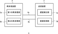
- FIG. 4 is a block diagram showing the configuration of the broadcasting system 1 according to the second embodiment.
- the broadcasting system 1 includes a remultiplexing device 2 and a transmitting device 3. Although one transmitting device 3 is shown in the example shown in FIG. 4, the broadcasting system 1 may include a plurality of transmitting devices 3.
- the remultiplexing device 2 has a first remultiplexing unit 2a and a second remultiplexing unit 2b.
- the first remultiplexing unit 2a re-reads the broadcasting data of the first resolution input to the first re-multiplexing unit 2a in order to output the broadcast data of the first resolution as an OFDM modulated wave from the transmission device 3. Perform multiple processing. Then, the first remultiplexing unit 2a outputs the first transmission data generated by the remultiplexing process to the transmission device 3 via the first line 4a.
- the first line 4a is, for example, a microwave line, but is not limited to this, and may be any other line.
- the second remultiplexing unit 2b is input to the second remultiplexing unit 2b in order to output the broadcast data of the second resolution together with the broadcast data of the first resolution as an OFDM modulated wave from the transmission device 3.
- the broadcast data of the second resolution is re-multiplexed.
- the second remultiplexing unit 2b outputs the second transmission data generated by the remultiplexing process to the transmission device 3 via the second line 4b.
- the second line 4b is, for example, the IP network 40b, but is not limited to this, and may be any other line different from the first line 4a.
- the second remultiplexing unit 2b is the difference between the delay times of the first line 4a and the second line 4b at the timing corresponding to the timing of the first packet of the OFDM frame set by the first remultiplexing unit 2a. Insert a delay control packet, which is a packet containing control information for compensating for. At that time, the second remultiplexing unit 2b sets the index value of the waiting time from the time when the delay control packet is received in the transmission device 3 to the start of the modulation processing for the packet following the delay control packet as the above-mentioned control information. Generate as.
- the transmission device 3 is a device that outputs the data received from the remultiplexing device 2 as an OFDM modulated wave, and has a delay correction unit 3a and a modulation processing unit 3b.
- the delay correction unit 3a adjusts the timing for starting the modulation processing for the packet following the delay control packet based on the control information included in the delay control packet generated by the second remultiplexing unit 2b of the remultiplexing device 2. .. Further, the modulation processing unit 3b modulates the broadcast data of the first resolution and the broadcast data of the second resolution and outputs them as an OFDM modulated wave.
- the second remultiplexing unit 2b of the remultiplexing device 2 generates a delay control packet for synchronizing the broadcast data of the first resolution and the broadcast data of the second resolution. .. Then, the modulation processing unit 3b of the transmission device 3 performs the modulation processing following the processing of the delay correction unit 3a at the timing adjusted by the delay correction unit 3a based on the delay control packet. Therefore, it is possible to realize synchronization of the output when broadcasting the broadcast data of the first resolution and the broadcast data of the second resolution.
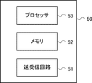
- FIG. 5 is a block diagram showing an example of the configuration of the computer 50 that performs the processing described in the embodiment.
- the computer 50 includes a transmission / reception circuit 51, a memory 52, and a processor 53.
- the transmission / reception circuit 51 is a transmission circuit and a reception circuit for transmitting / receiving data to / from other devices.
- the memory 52 is composed of, for example, a combination of a volatile memory and a non-volatile memory.
- the memory 52 is used to store software (computer program) containing one or more instructions executed by the processor 53.
- the processor 53 performs processing by reading software (computer program) from the memory 52 and executing the software (computer program).
- Non-transient computer-readable media include various types of tangible storage media (tangible studio media).
- Examples of non-temporary computer-readable media include magnetic recording media (eg, flexible disks, magnetic tapes, hard disk drives), optomagnetic recording media (eg, optomagnetic disks), CD-ROMs (Read Only Memory) CD-Rs, CDs. -R / W, including semiconductor memory (for example, mask ROM, PROM (Programmable ROM), EPROM (Erasable PROM), flash ROM, RAM (Random Access Memory)).
- the program may also be supplied to the computer by various types of temporary computer-readable media.
- Examples of temporary computer-readable media include electrical, optical, and electromagnetic waves.
- the temporary computer-readable medium can supply the program to the computer via a wired communication path such as an electric wire and an optical fiber, or a wireless communication path.
Landscapes
- Engineering & Computer Science (AREA)
- Signal Processing (AREA)
- Multimedia (AREA)
- Two-Way Televisions, Distribution Of Moving Picture Or The Like (AREA)
Abstract
第1の解像度の放送データと第2の解像度の放送データとを放送する場合の出力の同期を実現することができる再多重装置、放送システム、再多重方法、及びプログラムを提供する。再多重装置(2)は、第1の再多重部(2a)と第2の再多重部(2b)とを有する。第2の再多重部(2b)は、OFDMフレームの先頭パケットのタイミングに対応するタイミングで、第1の回線と第2の回線の遅延時間の差を補償するための制御情報を含むパケットである遅延制御パケットを挿入する。その際、第2の再多重部(2b)は、送信装置(3)において前記遅延制御パケットが受信された時点から前記遅延制御パケットに続くパケットに対する変調処理を開始するまでの待機時間の指標値を、前記制御情報として生成する。
Description
本発明は再多重装置、放送システム、再多重方法、及びプログラムに関する。
2K放送の規格であるARIB STD-B31では、SFN(Single Frequency Network)の同期方法として、概して、従属同期とリファレンス同期が示されているが、実際に運用されているものは、ほぼ、従属同期である。
ところで、日本では、4K放送に関して、衛星での4K放送が先行で商業化された。この放送において、演奏所から送信所へのデータの伝送には、2K放送で用いられていた回線とは別の種類の回線が用いられている。具体的には、MPEG-2 TS(Transport Stream)を伝送する既存の回線ではなく、IP(Internet Protocol)ネットワークが用いられている。TSを伝送する既存の回線は、伝送による遅延時間が固定であるが、IPネットワークでは、転送経路の変動又は負荷の変動などによって、伝送による遅延時間が一定量変動する。このため、演奏所から送信所へと、既存の2K放送用の伝送路で2K放送用のデータを伝送しつつ、4K放送用のデータをIPネットワークで伝送する場合、固定遅延を利用した既存の従属同期により、SFNの同期を実現できない。
関連する技術として、特許文献1に開示された技術が知られている。この文献では、フレーム先頭タイミングを絶対基準時刻(NTP(Network Time Protocol)情報など)を用いて特定することで、出力タイミングを決定している。
特許文献1に記載された同期方法は、絶対基準時刻を用いたリファレンス同期であり、従属同期を行う既存のシステムに適用するのは容易ではない。
本開示はこのような問題点を解決するためになされたものであり、第1の解像度の放送データと第2の解像度の放送データとを放送する場合の出力の同期を実現することができる再多重装置、放送システム、再多重方法、及びプログラムを提供することを目的とする。
本開示の第1の態様にかかる再多重装置は、
第1の解像度の放送データをOFDM(Orthogonal Frequency Division Multiplexing)変調波として1以上の送信装置から出力するために、入力された前記第1の解像度の放送データについて再多重処理を行い、当該再多重処理により生成された第1の伝送データを第1の回線を介して前記送信装置に出力する第1の再多重手段と、
第2の解像度の放送データを前記第1の解像度の放送データとともに前記OFDM変調波として前記送信装置から出力するために、入力された前記第2の解像度の放送データについて再多重処理を行い、当該再多重処理により生成された第2の伝送データを第2の回線を介して前記送信装置に出力する第2の再多重手段と、
を有し、
前記第2の再多重手段は、前記第1の再多重手段で設定されたOFDMフレームの先頭パケットのタイミングに対応するタイミングで、前記第1の回線と前記第2の回線の遅延時間の差を補償するための制御情報を含むパケットである遅延制御パケットを挿入し、
前記第2の再多重手段は、前記送信装置において前記遅延制御パケットが受信された時点から前記遅延制御パケットに続くパケットに対する変調処理を開始するまでの待機時間の指標値を、前記制御情報として生成する。
第1の解像度の放送データをOFDM(Orthogonal Frequency Division Multiplexing)変調波として1以上の送信装置から出力するために、入力された前記第1の解像度の放送データについて再多重処理を行い、当該再多重処理により生成された第1の伝送データを第1の回線を介して前記送信装置に出力する第1の再多重手段と、
第2の解像度の放送データを前記第1の解像度の放送データとともに前記OFDM変調波として前記送信装置から出力するために、入力された前記第2の解像度の放送データについて再多重処理を行い、当該再多重処理により生成された第2の伝送データを第2の回線を介して前記送信装置に出力する第2の再多重手段と、
を有し、
前記第2の再多重手段は、前記第1の再多重手段で設定されたOFDMフレームの先頭パケットのタイミングに対応するタイミングで、前記第1の回線と前記第2の回線の遅延時間の差を補償するための制御情報を含むパケットである遅延制御パケットを挿入し、
前記第2の再多重手段は、前記送信装置において前記遅延制御パケットが受信された時点から前記遅延制御パケットに続くパケットに対する変調処理を開始するまでの待機時間の指標値を、前記制御情報として生成する。
本開示の第2の態様にかかる放送システムは、
再多重装置と、
前記再多重装置から受信したデータをOFDM変調波として出力する1以上の送信装置と、
を備え、
前記再多重装置は、
第1の解像度の放送データをOFDM変調波として前記送信装置から出力するために、入力された前記第1の解像度の放送データについて再多重処理を行い、当該再多重処理により生成された第1の伝送データを第1の回線を介して前記送信装置に出力する第1の再多重手段と、
第2の解像度の放送データを前記第1の解像度の放送データとともに前記OFDM変調波として前記送信装置から出力するために、入力された前記第2の解像度の放送データについて再多重処理を行い、当該再多重処理により生成された第2の伝送データを第2の回線を介して前記送信装置に出力する第2の再多重手段と、
を有し、
前記第2の再多重手段は、前記第1の再多重手段で設定されたOFDMフレームの先頭パケットのタイミングに対応するタイミングで、前記第1の回線と前記第2の回線の遅延時間の差を補償するための制御情報を含むパケットである遅延制御パケットを挿入し、
前記第2の再多重手段は、前記送信装置において前記遅延制御パケットが受信された時点から前記遅延制御パケットに続くパケットに対する変調処理を開始するまでの待機時間の指標値を、前記制御情報として生成し、
前記送信装置は、
前記制御情報に基づいて、前記遅延制御パケットに続くパケットに対する変調処理を開始するタイミングを調整する遅延補正手段と、
前記第1の解像度の放送データと前記第2の解像度の放送データとを変調して、OFDM変調波として出力する変調処理手段と
を有する。
再多重装置と、
前記再多重装置から受信したデータをOFDM変調波として出力する1以上の送信装置と、
を備え、
前記再多重装置は、
第1の解像度の放送データをOFDM変調波として前記送信装置から出力するために、入力された前記第1の解像度の放送データについて再多重処理を行い、当該再多重処理により生成された第1の伝送データを第1の回線を介して前記送信装置に出力する第1の再多重手段と、
第2の解像度の放送データを前記第1の解像度の放送データとともに前記OFDM変調波として前記送信装置から出力するために、入力された前記第2の解像度の放送データについて再多重処理を行い、当該再多重処理により生成された第2の伝送データを第2の回線を介して前記送信装置に出力する第2の再多重手段と、
を有し、
前記第2の再多重手段は、前記第1の再多重手段で設定されたOFDMフレームの先頭パケットのタイミングに対応するタイミングで、前記第1の回線と前記第2の回線の遅延時間の差を補償するための制御情報を含むパケットである遅延制御パケットを挿入し、
前記第2の再多重手段は、前記送信装置において前記遅延制御パケットが受信された時点から前記遅延制御パケットに続くパケットに対する変調処理を開始するまでの待機時間の指標値を、前記制御情報として生成し、
前記送信装置は、
前記制御情報に基づいて、前記遅延制御パケットに続くパケットに対する変調処理を開始するタイミングを調整する遅延補正手段と、
前記第1の解像度の放送データと前記第2の解像度の放送データとを変調して、OFDM変調波として出力する変調処理手段と
を有する。
本開示の第3の態様にかかる再多重方法では、
第1の解像度の放送データをOFDM変調波として1以上の送信装置から出力するために、入力された前記第1の解像度の放送データについて再多重処理を行い、当該再多重処理により生成された第1の伝送データを第1の回線を介して前記送信装置に出力し、
第2の解像度の放送データを前記第1の解像度の放送データとともに前記OFDM変調波として前記送信装置から出力するために、入力された前記第2の解像度の放送データについて再多重処理を行い、当該再多重処理により生成された第2の伝送データを第2の回線を介して前記送信装置に出力し、
前記第2の解像度の放送データについての再多重処理では、
前記第1の回線と前記第2の回線の遅延時間の差を補償するための制御情報を含むパケットである遅延制御パケットを生成し、
前記第1の解像度の放送データについての再多重処理で設定されたOFDMフレームの先頭パケットのタイミングに対応するタイミングで、前記遅延制御パケットを挿入し、
前記遅延制御パケットの生成では、前記送信装置において前記遅延制御パケットが受信された時点から前記遅延制御パケットに続くパケットに対する変調処理を開始するまでの待機時間の指標値を、前記制御情報として生成する。
第1の解像度の放送データをOFDM変調波として1以上の送信装置から出力するために、入力された前記第1の解像度の放送データについて再多重処理を行い、当該再多重処理により生成された第1の伝送データを第1の回線を介して前記送信装置に出力し、
第2の解像度の放送データを前記第1の解像度の放送データとともに前記OFDM変調波として前記送信装置から出力するために、入力された前記第2の解像度の放送データについて再多重処理を行い、当該再多重処理により生成された第2の伝送データを第2の回線を介して前記送信装置に出力し、
前記第2の解像度の放送データについての再多重処理では、
前記第1の回線と前記第2の回線の遅延時間の差を補償するための制御情報を含むパケットである遅延制御パケットを生成し、
前記第1の解像度の放送データについての再多重処理で設定されたOFDMフレームの先頭パケットのタイミングに対応するタイミングで、前記遅延制御パケットを挿入し、
前記遅延制御パケットの生成では、前記送信装置において前記遅延制御パケットが受信された時点から前記遅延制御パケットに続くパケットに対する変調処理を開始するまでの待機時間の指標値を、前記制御情報として生成する。
本開示の第4の態様にかかるプログラムは、
第1の解像度の放送データをOFDM変調波として1以上の送信装置から出力するために、入力された前記第1の解像度の放送データについて再多重処理を行い、当該再多重処理により生成された第1の伝送データを第1の回線を介して前記送信装置に出力する第1の再多重ステップと、
第2の解像度の放送データを前記第1の解像度の放送データとともに前記OFDM変調波として前記送信装置から出力するために、入力された前記第2の解像度の放送データについて再多重処理を行い、当該再多重処理により生成された第2の伝送データを第2の回線を介して前記送信装置に出力する第2の再多重ステップと、
をコンピュータに実行させ、
前記第2の再多重ステップでは、前記第1の再多重ステップで設定されたOFDMフレームの先頭パケットのタイミングに対応するタイミングで、前記第1の回線と前記第2の回線の遅延時間の差を補償するための制御情報を含むパケットである遅延制御パケットを挿入し、
前記第2の再多重ステップでは、前記送信装置において前記遅延制御パケットが受信された時点から前記遅延制御パケットに続くパケットに対する変調処理を開始するまでの待機時間の指標値を、前記制御情報として生成する。
第1の解像度の放送データをOFDM変調波として1以上の送信装置から出力するために、入力された前記第1の解像度の放送データについて再多重処理を行い、当該再多重処理により生成された第1の伝送データを第1の回線を介して前記送信装置に出力する第1の再多重ステップと、
第2の解像度の放送データを前記第1の解像度の放送データとともに前記OFDM変調波として前記送信装置から出力するために、入力された前記第2の解像度の放送データについて再多重処理を行い、当該再多重処理により生成された第2の伝送データを第2の回線を介して前記送信装置に出力する第2の再多重ステップと、
をコンピュータに実行させ、
前記第2の再多重ステップでは、前記第1の再多重ステップで設定されたOFDMフレームの先頭パケットのタイミングに対応するタイミングで、前記第1の回線と前記第2の回線の遅延時間の差を補償するための制御情報を含むパケットである遅延制御パケットを挿入し、
前記第2の再多重ステップでは、前記送信装置において前記遅延制御パケットが受信された時点から前記遅延制御パケットに続くパケットに対する変調処理を開始するまでの待機時間の指標値を、前記制御情報として生成する。
本開示によれば、第1の解像度の放送データと第2の解像度の放送データとを放送する場合の出力の同期を実現することができる再多重装置、放送システム、再多重方法、及びプログラムを提供できる。
以下、図面を参照して本発明の実施の形態について説明する。
<実施の形態1>
図1は、実施の形態1にかかる放送システム10の構成の一例を示す模式図である。図1に示すように、放送システム10は、再多重装置20と1以上の送信装置30とを備えている。例えば、再多重装置20は、演奏所に設置された装置であり、送信装置30は、送信所に設置された装置である。放送システム10において、再多重装置20から送信装置30へと放送データが送信され、送信装置30は、放送波を出力する。ここで、放送システム10は、単一周波数ネットワーク(SFN)により、放送を行うシステムである。すなわち、1以上の送信装置30は、同じ周波数帯を用いて、放送波を出力する。また、本実施の形態では、放送システム10は、2K放送のための信号と4K放送のための信号を、同じ周波数帯を用いて送信装置30から出力する。放送システム10は、GPS(Global Positioning System)のPPS(Pulse Per Second)信号などのような基準信号を用いることなく、SFNの同期を実現する。すなわち、放送システム10は、リファレンス同期ではなく、従属同期を行う放送システムである。
<実施の形態1>
図1は、実施の形態1にかかる放送システム10の構成の一例を示す模式図である。図1に示すように、放送システム10は、再多重装置20と1以上の送信装置30とを備えている。例えば、再多重装置20は、演奏所に設置された装置であり、送信装置30は、送信所に設置された装置である。放送システム10において、再多重装置20から送信装置30へと放送データが送信され、送信装置30は、放送波を出力する。ここで、放送システム10は、単一周波数ネットワーク(SFN)により、放送を行うシステムである。すなわち、1以上の送信装置30は、同じ周波数帯を用いて、放送波を出力する。また、本実施の形態では、放送システム10は、2K放送のための信号と4K放送のための信号を、同じ周波数帯を用いて送信装置30から出力する。放送システム10は、GPS(Global Positioning System)のPPS(Pulse Per Second)信号などのような基準信号を用いることなく、SFNの同期を実現する。すなわち、放送システム10は、リファレンス同期ではなく、従属同期を行う放送システムである。
なお、2Kとは、画面解像度がフルハイビジョンである映像の総称である。すなわち、2Kとは、横2000程度×縦1000程度となるような映像の総称である。例えば、2Kの画面解像度とは、横2048×縦1080や、横1920×縦1080、横2048×縦1152、横2560×縦1600、横1440×縦1080等である。また、4Kとは、画面解像度がフルハイビジョンの4倍である映像の総称である。すなわち、4Kとは、画面解像度が横4000程度×縦2000程度となるような映像の総称である。例えば、4Kの画面解像度とは、横4096×縦2160や、横3840×縦2160、横4096×縦2304、横4096×縦2048等である。
再多重装置20には、2K放送用の放送データと、この2K放送用の放送データと同時に同じ周波数帯を用いて送信装置30から送信されることとなる4K放送用の放送データが入力される。これらの放送データは、例えば、再多重装置20を備えた演奏所に設けられた他の装置から光回線又は同軸ケーブルなどを介して、再多重装置20に入力される。再多重装置20は、これらの放送データに対して、後述する再多重処理を行ない、再多重処理が行われたデータを各送信装置30に出力する。
各送信装置30は、再多重装置20から受信したデータに対して、変調部300によりOFDM変調を行ない、受信したデータをOFDM変調波として出力する。ここで、各送信装置30は、変調処理の開始タイミングを調整することにより、各送信装置30からの出力タイミングを同期させる。すなわち、各送信装置30は、SFNの同期を実現する。本実施の形態では、2K放送のための信号と4K放送のための信号をOFDM変調波として同時に出力するため、複数の送信装置30間での出力タイミングの同期に加え、2K放送用のデータと4K放送用のデータの変調処理の開始タイミングを調整する必要がある。このために、再多重装置20は、再多重装置20から送信装置30に送信するパケット列に、このタイミングを制御するためのパケット(以下、タイミングパケット若しくは遅延制御パケットとも称す)を挿入する。
放送システム10において、2K放送用のデータと、4K放送用のデータは、それぞれ別の回線で再多重装置20から各送信装置30に伝送される。本実施の形態では、2K放送用のデータは、1対1のマイクロ波回線40aで送信され、4K放送用のデータは、IPネットワーク40bで伝送される。図1において、2K放送用のデータの伝送路が実線で示され、4K放送用のデータの伝送路が破線で示されている。なお、一例として、2K放送用のデータは、再多重装置20から送信装置30へ無線送信され、4K放送用のデータは、再多重装置20から送信装置30へ有線送信されるが、これらの伝送が無線又は有線に限られなくてもよい。また、マイクロ波回線40aによる再多重装置20から送信装置30への伝送は、中継装置(不図示)を介して行われてもよい。
ここで、マイクロ波回線40aによる伝送では、伝送路における遅延時間は一定である。すなわち、再多重装置20から、ある送信装置30への伝送の遅延時間は遅延時間Aで一定であり、再多重装置20から、別の送信装置30への伝送の遅延時間は遅延時間Bで一定である。なお、一般的に、遅延時間Aと遅延時間Bは異なる。これに対し、IPネットワーク40bでは、再多重装置20からある送信装置30への伝送の遅延時間は、一定の変動範囲内で変動する。また、一般的に、IPネットワーク40bにおける4K放送用データの伝送の遅延時間は、マイクロ波回線40aによる2K放送用データの伝送の遅延時間よりも、短い。
次に、再多重装置20の構成について説明する。図2は、実施の形態1にかかる再多重装置20の構成の一例を示すブロック図である。図2に示すように、再多重装置20は、主に、2K再多重部210と、4K再多重部220と、パケット出力部230とを有する。2K再多重部210は、2K放送データをOFDM変調波として1以上の送信装置30から出力するために、入力された2K放送データについて再多重処理を行う。これにより、当該再多重処理により生成された第1の伝送データ(2K伝送データ)がマイクロ波回線40aを介して送信装置30に出力される。また、4K再多重部220は、4K放送データを2K放送データとともにOFDM変調波として送信装置30から出力するために、入力された4K放送データについて再多重処理を行う。これにより、当該再多重処理により生成された第2の伝送データ(4K伝送データ)がIPネットワーク40bを介して送信装置30に出力される。
2K再多重部210には、2K放送用のデータが入力される。このデータは、MPEG-2で規格化されているTSパケットである。同様に、4K再多重部220には、4K放送用のデータが入力される。このデータは、例えば、TSパケットであるが、TLV(Type Length Value)パケットであってもよい。2K再多重部210及び4K再多重部220に入力されるデータは、例えば、映像及び音声などが多重化されたデータである。
2K再多重部210は、公知の再多重処理を行う処理部である。2K再多重部210は、送信装置30において、2K放送用データに対して行われる一次変調の変調パラメータ(例えば、多値度、符号化率など)の所定のパラメータ値に基づいて、送信装置30に入力するデータレートを決定する。そして、2K再多重部210は、決定したデータレートで2K再多重部210から放送データを出力するよう、ヌル(Null)データが格納されたパケットであるヌル(Null)パケットを、2K再多重部210に入力されるデータに対して挿入する。すなわち、2K再多重部210は、変調パラメータに基づいて特定される所定のデータレートで、トランスポートストリーム(TS)を出力する。
また、2K再多重部210は、映像及び音声などのデータを含むトランスポートストリームの他に、処理クロック(CLK)と、フレーム同期信号(Fsync)を送信装置30に出力する。これらは、マイクロ波回線40aを介して、送信装置30で受信される。なお、2K再多重部210によるTS、CLK、Fsyncの出力については、公知の技術であるため、その詳細な説明については省略する。処理クロック(CLK)は、再多重装置20の処理において用いられたクロックと同じであり、送信装置30は、再多重装置20から受信した処理クロックに従って、処理を行うこととなる。また、フレーム同期信号(Fsync)は、OFDMフレームの周期(OFDMフレームのフレーム長)と同期した信号であり、1つのOFDMフレームを構成することとなるデータ群(パケット群)の開始を示す信号である。なお、OFDMフレームの周期は、OFDM変調の変調パラメータ(モード及びガードインターバル)によって、一意に特定される。このように、2K再多重部210は、送信装置30で構成されこととなる各OFDMフレームの先頭パケットのタイミングを設定しているとも言える。
また、2K再多重部210は、公知の再多重部と同様、TSに、TMCC(Transmission and Multiplexing Configuration Control)情報などを含むIIP(ISDB-T Information Packet)を多重する。より詳細には、2K再多重部210は、フレーム同期信号(Fsync)の1周期ごとに、すなわち、OFDMフレームの1周期ごとに、TSに、IIPを多重する。TMCC情報は、送信装置30における変調を規定する変調パラメータなどのパラメータを含む情報である。ここで、2K再多重部210により多重されるTMCC情報は、ARIB STD―B31で規定されているTMCC_synchronization_wordを含む。TMCC_synchronization_wordの値には、第1の値W0か第2の値W1のいずれかの値が設定される。2K再多重部210は、フレーム同期信号(Fsync)の1周期ごとに、すなわち、OFDMフレームの1周期ごとに、TMCC_synchronization_wordの値を切り替えて、TSに多重する。このため、2K再多重部210は、フレーム同期信号(Fsync)の1周期ごとに、第1の値W0と第2の値W1を交互に出力する。このように、パラメータTMCC_synchronization_wordは、当該パラメータが多重されているデータ群により構成されるOFDMフレームが奇数番目のフレームであるか偶数番目のフレームであるかを示す情報ともいうことができる。または、当該パラメータが多重されているデータ群(パケット群)が奇数番目のデータ群であるか偶数番目のデータ群であるかを示す情報ともいうことができる。
また、IIPパケットには、MPEG-2トランスポートストリームで用いられているcontinuity_counterが含まれる。したがって、2K再多重部210は、フレーム同期信号(Fsync)の1周期ごとに、すなわち、OFDMフレームの1周期ごとに、continuity_counterの値を、TSに多重して出力する。continuity_counterは、伝送されるTSパケットを順番にカウントするパラメータであり、TSパケットに含まれているパラメータである。IIPパケットには、当該IIPパケットが多重されるTSパケット群のうちの例えば先頭のTSパケットのcontinuity_counterの値が格納される。フレーム同期信号(Fsync)の1周期ごとに2K再多重部210が出力するIIPパケットに含まれるcontinuity_counterの値は、フレーム同期信号(Fsync)の1周期ごとに変動することとなる。
このように、2K再多重部210は、OFDMフレームの周期毎に、所定のパラメータのパラメータ値を2K放送データに多重してトランスポートストリームを生成する。
次に、4K再多重部220について説明する。図2に示すように、4K再多重部220は、レート調整部221とタイミングパケット挿入部222とを有する。
レート調整部221は、送信装置30において2K放送用データに対して行われる一次変調の変調パラメータの所定のパラメータ値と、4K放送用データに対して行われる一次変調の変調パラメータの所定のパラメータ値とに基づいて、送信装置30に入力するデータレートを決定する。本実施の形態では、放送システム10は、2K放送用データと4K放送用データを、同じ周波数帯を用いたOFDM変調波として、送信装置30から出力する。このため、伝送可能容量を2K放送用データの伝送と4K放送用データの伝送とで共用する。このとき、本実施の形態では、4K放送用データの伝送は、伝送可能容量のうち、2K放送用データの伝送に用いられた容量の残りの容量である空き容量を用いて行われる。このため、レート調整部221は、4K放送用データに対して行われる一次変調の変調パラメータ値のみならず、2K放送用データに対して行われる一次変調の変調パラメータ値に基づいて、4K放送用データについてのデータレートを決定する。そして、レート調整部221は、決定したデータレートで4K再多重部220から放送データを出力するよう、ヌル(Null)データが格納されたパケットであるヌル(Null)パケットを、レート調整部221に入力されるデータに対して挿入する。すなわち、レート調整部221は、変調パラメータに基づいて特定される所定のデータレートで、データを出力する。
タイミングパケット挿入部222は、タイミングパケット(遅延制御パケットとも称される)を生成し、レート調整部221から出力されたデータ列に、生成したタイミングパケットを挿入する。タイミングパケットは、2K放送用のデータを伝送する回線と4K放送用のデータを伝送する回線の伝送の遅延時間の差を補償するための制御情報を含むパケットである。換言すると、タイミングパケットは、再多重装置20と送信装置30の間のマイクロ波回線40aの伝送遅延と再多重装置20と送信装置30の間のIPネットワーク40bの伝送遅延の差を補償するための制御情報を含むパケットである。制御情報は、タイミングパケット挿入部222により送信装置30毎に生成される。
タイミングパケット挿入部222は、OFDMフレームの先頭パケットのタイミングに対応するタイミングで、タイミングパケットを挿入する。すなわち、タイミングパケット挿入部222は、先頭パケットの位置に対応する位置に、タイミングパケットを挿入する。具体的には、タイミングパケット挿入部222は、先頭パケットと対応する、4K放送データのパケットの直前に、タイミングパケットを挿入する。このとき、タイミングパケット挿入部222は、先頭パケットと対応する4K放送データのパケットの直前のパケット(先頭パケットと対応する4K放送データのパケットの1つ前のパケット)を、タイミングパケットに置き換える。したがって、タイミングパケットに置換されるパケットは喪失される。このため、レート調整部221は、置換される位置のパケットをNullパケットとしておく。
ここで、タイミングパケットに格納される制御情報は、後述する送信装置30の4K遅延補正部310が遅延補償のために後段の変調処理の開始を遅延させる際の待機時間(遅延時間)の指標値を含む。より詳細には、制御情報は、送信装置30においてタイミングパケットパケットが受信された時点からタイミングパケットに続くパケットに対する変調処理を開始するまでの待機時間の指標値を含む。タイミングパケット挿入部222は、制御情報として指定するこの指標値を、2K伝送路遅延情報と、4K伝送路遅延情報と、OFDMフレームの周期とに基づいて特定する。2K伝送路遅延情報は、再多重装置20と送信装置30の間の伝送に用いられるマイクロ波回線40aの送信装置30毎の遅延時間である。これは、予め測定された固定の遅延時間である。また、4K伝送遅延情報は、再多重装置20と送信装置30の間の伝送に用いられるIPネットワーク40bの送信装置30毎の遅延時間である。これは、予め測定された結果に基づいて設定された時間である。上述の通り、IPネットワーク40bの遅延時間は、変動する。このため、4K伝送遅延情報として、例えば、測定結果として得られた最小遅延時間が設定されてもよいし、平均遅延時間が設定されてもよい。
上述の通り、制御情報は、送信装置30毎に生成される。ここで、ある送信装置30に対する制御情報の生成について説明する。ここでは、その送信装置30を送信装置Aと称すこととする。送信装置Aについての4K伝送路遅延情報が示す遅延時間が50ミリ秒であり、送信装置Aについての2K伝送路遅延情報が示す遅延時間が300ミリ秒であるとする。また、OFDMフレームの周期が231.336ミリ秒であるとする。この場合、送信装置Aでは、2K放送データが、4K放送データに比べて、250ミリ秒遅れて受信されることとなる。この250ミリ秒という遅延時間の差は、OFDMフレームの1周期に相当する時間以上かつ2周期に相当する時間未満である。この場合、4K放送データのタイミングパケットを送信装置Aが受信してから、1周期分の時間を待った上で最初に受信した2K放送データの先頭パケットが、当該タイミングパケットの直後のパケットと時間的に同期しているパケットとなる。したがって、この場合、タイミングパケットの直後のパケットが、送信装置Aにおいてどのタイミングで受信された先頭パケットに対応するかを送信装置Aが特定できるように、タイミングパケット挿入部222は、送信装置Aに対する指標値を例えば1として、送信装置Aに送信する。このように、タイミングパケット挿入部222は、送信装置Aに対する2つの伝送路の遅延時間の差がOFDMフレームのN(Nは整数)周期に相当する時間以上かつN+1周期に相当する時間未満である場合、送信装置Aに対する指標値として、Nを設定する。なお、本実施の形態では、指標値として、周期を設定しているが、具体的な時間を設定してもよい。すなわち、タイミングパケット挿入部222は、送信装置Aに対する2つの伝送路の遅延時間の差の値を指標値として設定してもよい。この場合、タイミングパケット挿入部222は、OFDMフレームの周期を用いずに、指標値を特定してもよい。タイミングパケット挿入部222は、送信装置30毎に、上述のようにして、指標値を決定する。
ところで、上述した通り、IPネットワーク40bの遅延時間は変動する。このため、設定された4K伝送路遅延情報に基づいて決定された指標値に基づいて遅延補償を行った場合、送信装置30は、誤って、1フレーム分ずれたタイミングで4K放送データの変調処理を行ってしまう恐れがある。よって、指標値以外に参照される値が存在することが好ましい。このため、本実施の形態では、タイミングパケット挿入部222は、制御情報として、OFDMフレームの周期毎に、2K再多重部210により多重された所定のパラメータのパラメータ値を用いる。すなわち、本実施の形態では、2K再多重部210は、指標値と、パラメータ値とを含む制御情報を含む遅延制御パケットを生成する。制御情報として用いられる所定のパラメータは、具体的には、上述したTMCC_synchronization_word及びcontinuity_counterである。これらのパラメータ値は、フレーム周期毎に変動する値であるため、フレームを識別する情報として用いることができる。したがって、送信装置30において、4K放送データのタイミングパケットに含まれるパラメータ値と、2K放送データのIIPパケットのパラメータ値とを比較することにより、送信装置30において、2K放送データのパケットと4K放送データのパケットの時間的な対応をより正確に特定できる。なお、指標値とは異なり、制御情報として設定されるパラメータ値には、各送信装置30に共通の値が設定される。
次に、パケット出力部230について説明する。パケット出力部230は、4K再多重部220から出力されたデータを、IPネットワーク40bで伝送するための適切な形式のデータに変換し、変換されたデータをIPネットワーク40bを介して送信装置30に出力する。具体的には、例えば、パケット出力部230は、4K再多重部220から出力されたデータに対して、MAC(Media Access Control)フレーミング処理、IP(Internet Protocol)フレーミング処理、及びUDP(User Datagram Protocol)フレーミング処理を行う。
次に、送信装置30の変調部300について説明する。図3A~3Cは、変調部300の構成の一例を示すブロック図である。図3A~3Cに示すように、変調部300は、SFN遅延補正部301、外符号処理部302、階層分割部303、エネルギー拡散部304a、b、2K遅延補正部305a、b、バイトインターリーブ処理部306a、b、畳込み符号化処理部307a、b、ビットインターリーブ処理部308a、b、マッピング処理部309a、b、4K遅延補正部310、FECブロック構成部311、エネルギー拡散部312、BCH符号化処理部313、LDPC符号化処理部314、ビットインターリーブ処理部315、マッピング処理部316、階層合成部317、時間インターリーブ処理部318、周波数インターリーブ処理部319、OFDMフレーム構成部320、IFFT処理部321a、b、ガードインターバル付加部322a、b、直交変調処理部323a、bを含む。これらの構成要素は、再多重装置20から受信した処理クロック(CLK)に従って、処理を行う。以下、変調部300の各構成要素について説明する。なお、図3A~3Cは、階層伝送が行われる場合の変調部300の構成を示しており、マイクロ波回線40aを用いた2K放送データの伝送では、より詳細には、2階層のデータが伝送されているものとする。
送信装置30から再多重装置20へとマイクロ波回線40aを介して伝送された2K放送データ及びフレーム同期信号(Fsync)と、送信装置30から再多重装置20へとIPネットワーク40bを介して伝送された4K放送データは、SFN遅延補正部301に入力される。
SFN遅延補正部301は、各送信装置30間の伝送遅延の差を補償するための補正処理を行う。具体的には、SFN遅延補正部301は、所定の待機時間だけ入力されたデータを一時的に保持し、その後、後段の処理ブロックにデータを出力する。すなわち、SFN遅延補正部301は、後続の処理の開始を所定の待機時間だけ遅延させる処理を行う。なお、この待機時間は、例えば、再多重装置20から各送信装置30への伝送における送信装置30毎の伝送遅延時間のうちの最大の伝送遅延時間に基づいて予め設定されている。
SFN遅延補正部301により遅延補正が行われた2K放送データは、外符号処理部302と、4K遅延補正部310とに入力される。また、SFN遅延補正部301により遅延補正が行われた4K放送データは、4K遅延補正部310に入力される。
外符号処理部302には、上述した2つの階層のデータが入力される。そして、外符号処理部302は、入力されたデータに、所定の検査用の符号を付す処理を施す。本例では、外符号処理部302は、入力されたデータに、リードソロモン符号(RS(204,188))を付す処理を施す。そして、外符号処理部302は、検査用の符号が付されたデータを階層分割部303に出力する。
階層分割部303は、2つの階層のデータを分割し、一方のデータをエネルギー拡散部304aに出力し、他方のデータをエネルギー拡散部304bに出力する。
エネルギー拡散部304aは、階層分割部303から出力されたデータに所定のエネルギー拡散処理を施し、処理結果を2K遅延補正部305aに出力する。同様に、エネルギー拡散部304bは、階層分割部303から出力されたデータに所定のエネルギー拡散処理を施し、処理結果を2K遅延補正部305bに出力する。
2K遅延補正部305a、bは、エネルギー拡散部304aからマッピング処理部309aまでの処理時間と、エネルギー拡散部304bからマッピング処理部309bまでの処理時間の差を補償するための遅延補正を行う。すなわち、2K遅延補正部305a、bは、後続の処理の終了タイミングがそろうように、所定の待機時間だけ後続の処理の開始を遅延させる処理を行う。
2K遅延補正部305a、bの処理の後、バイトインターリーブ処理部306a、bの処理が行われる。バイトインターリーブ処理部306a、bは、バイト単位での並び替えを行うバイトインターリーブの処理を行う。なお、インターリーブの深さは、例えば、12バイトである。
畳込み符号化処理部307a、bは、バイトインターリーブ処理部306a、bによってそれぞれ畳込みバイトインターリーブの処理が施されたビットストリームに、所定の畳込み符号化処理をそれぞれ施す。具体的には、畳込み符号化処理部a、bは、当該ビットストリームに、例えば、拘束長k=7、符号化率1/2の原符号をマザーコードとし、階層ごとにそれぞれ設定された符号化率で、パンクチャード畳込み符号の符号化処理を施す。
ビットインターリーブ処理部308a、bは、畳込み符号化処理部307a、bにより符号化処理が施されたビットストリームに、後段のマッピング処理部309a、bでなされるマッピングに応じたビットインターリーブの処理を施す。
マッピング処理部309a、bは、ビットインターリーブ処理部308a、bによってビットインターリーブの処理が施されたビットストリームに、マッピング処理を行う。具体的には、マッピング処理部309aは、例えば、ビットインターリーブ処理部308aがビットインターリーブの処理を施したビットストリームに、QPSK(Quadrature Phase shift Keying)のマッピング処理を施す。また、マッピング処理部309bは、例えば、ビットインターリーブ処理部308bがビットインターリーブの処理を施したビットストリームに、64QAM(Quadrature Amplitude Modulation)等のマッピング処理を施す。そして、マッピング処理部309a、bは、ビットストリームがマッピングされた信号を階層合成部317に出力する。
4K遅延補正部310は、再多重装置20により挿入されたタイミングパケットに基づいて、再多重装置20から送信装置30への伝送におけるマイクロ波回線40aとIPネットワーク40bの伝送遅延の差を補償するための補正処理を行う。具体的には、4K遅延補正部310は、タイミングパケットに含まれる制御情報に基づいて、タイミングパケットに続くパケットに対する後続の処理の開始タイミングを調整する。本実施の形態では、4K遅延補正部310は、以下で述べるように、制御情報に含まれる指標値とパラメータ値とを参照して、後続の処理を開始するタイミングを調整するが、パラメータ値を参照せずに、後続の処理を開始するタイミングを調整してもよい。この場合、制御情報はパラメータ値を含まなくてもよい。また、4K遅延補正部310は、TMCC_synchronization_wordとcontinuity_counterのうち、いずれか一方のパラメータ値のみを参照して、後続の処理を開始するタイミングを調整してもよい。
4K遅延補正部310は、タイミングパケットが受信されると(すなわち、4K遅延補正部310にタイミングパケットが入力されると)、指標値を参照する。上述の通り、この指標値は、マイクロ波回線40aとIPネットワーク40bの遅延時間の差がどのくらいあるかを示す情報である。例えば、この指標値の値がN(周期)である場合、4K遅延補正部310は、送信装置30におけるマイクロ波回線40aとIPネットワーク40bの遅延時間の差が、OFDMフレームのN周期に相当する時間以上かつN+1周期に相当する時間未満であることを検知することができる。すなわち、タイミングパケットが4K遅延補正部310に入力されてから、N周期分の時間を待った上で最初に受信した2K放送データのフレームの先頭パケットが、当該タイミングパケットの直後のパケットと時間的に同期しているパケットであることを検知することができる。ここで、2K放送データのフレームの先頭パケットは、フレーム同期信号(Fsync)を4K遅延補正部310が監視することにより特定される。なお、4K遅延補正部310は、フレーム同期信号(Fsync)を監視するのではなく、2K放送データに含まれるIIPパケットを参照することにより、2K放送データにおけるフレームの先頭パケットを特定してもよい。IIPパケットには、IIPパケットのどれだけ後ろに先頭パケットが存在するかを示す情報が含まれているため、この情報を参照することにより、先頭パケットを特定できるからである。この場合、4K遅延補正部310は、フレーム同期信号(Fsync)を監視しなくてもよい。
4K遅延補正部310は、指標値に基づいて、タイミングパケットの直後のパケットと時間的に同期している2K放送データのパケットを特定すると、その特定に誤りがないかを検証する。具体的には、4K遅延補正部310は、タイミングパケットに含まれるパラメータ値(TMCC_synchronization_word及びcontinuity_counter)と、特定されたパケットに対応するIIPパケットに格納されているこれらのパラメータ値とを比較して、両者が一致しているか否かを判定する。両者が一致している場合、4K遅延補正部310は、指標値に基づく特定に誤りがないと判定する。これに対し、両者が一致しない場合、4K遅延補正部310は、指標値に基づく特定に誤りがあると判定する。この場合、4K遅延補正部310は、例えば、指標値に基づいて特定された先頭パケットの次の先頭パケットをタイミングパケットの直後のパケットと時間的に同期している2K放送データのパケットである特定する。
4K遅延補正部310は、特定に誤りがないことが検証されると、特定された先頭パケットが入力される時点まで、タイミングパケットの後続のパケットを一時的に保持し、その後、後段の処理ブロックにデータを出力する。換言すると、4K遅延補正部310は、タイミングパケットの後続のパケット一時的に保持し、その後、4K遅延補正部310の処理に後続する処理を開始させる。このように、4K遅延補正部310は、後続の処理の開始を、遅延させる処理を行う。
なお、4K遅延補正部310は、2K放送データに対する変調部300の処理時間と、4K放送データに対する変調部300の処理時間との差を補償するための遅延補正を行ってもよい。すなわち、4K遅延補正部310は、後続の処理の終了タイミングがそろうように、所定の待機時間だけ、後続の処理の開始をさらに遅延させてもよい。
4K遅延補正部310の処理の後、FECブロック構成部311の処理が行われる。FECブロック構成部311は、入力されたパケットからFEC(Forward Error Correction)ブロックを生成する。すなわち、FECブロック構成部311は、入力されたビット列を、誤り訂正符号化を行うためのフォーマットに並べてエネルギー拡散部312に出力する。
エネルギー拡散部312は、FECブロック構成部311から出力されたデータに所定のエネルギー拡散処理を施し、処理結果をBCH符号化処理部313に出力する。
BCH符号化処理部313は、エネルギー拡散部312から出力されたビット列に、誤り訂正外符号であるBCH(Bose-Chaudhuri-Hocquenghem)符号化パリティを付加して、LDPC符号化処理部314に出力する。
LDPC符号化処理部314は、BCH符号化処理部313から出力されたビット列に、誤り訂正内符号であるLDPC(Low-Density Parity-Check)符号化パリティを付加して、ビットインターリーブ処理部315に出力する。
ビットインターリーブ処理部315は、LDPC符号化処理部314による処理が施されたビットストリームに、後段のマッピング処理部316でなされるマッピングに応じたビットインターリーブの処理を施す。
マッピング処理部316は、ビットインターリーブ処理部315によってビットインターリーブの処理が施されたビットストリームに、マッピング処理を行う。具体的には、マッピング処理部316は、例えば、ビットインターリーブ処理部315がビットインターリーブの処理を施したビットストリームに、4096QAM、1024QAM、又は256QAM等のマッピング処理を施す。そして、マッピング処理部316は、ビットストリームがマッピングされた信号を階層合成部317に出力する。
階層合成部317は、予め指定されたパラメータで、マッピング処理部309a、309b、316がそれぞれ出力した信号を合成してデータセグメントに挿入するとともに、速度変換を行う階層合成処理を行う。
時間インターリーブ処理部318は、変調(マッピング処理)後のシンボルデータを時間的に分散させ、耐フェージング性能を改善させるために、変調シンボル単位(I,Q軸単位)で、階層合成処理が施された信号に所定の時間インターリーブ処理を施す。
周波数インターリーブ処理部319は、時間に応じて、セグメント内でキャリア(搬送波)の周波数を変更(ローテーション)させたり、各セグメント間で使用する周波数帯を交換したりする周波数インターリーブの処理を行う。
OFDMフレーム構成部320には、周波数インターリーブ処理部319によって周波数インターリーブの処理が施された信号と、パイロット信号と、TMCC信号と、AC(Auxiliary Channel)信号とが入力される。なお、パイロット信号は、例えば、連続キャリアである。また、TMCC信号は、再多重装置20から受信したTMCC情報に基づいて生成される信号である。AC信号は、例えば、放送に関する付加情報を伝送するための拡張用信号である。
OFDMフレーム構成部320は、入力された各信号に基づいてOFDMフレームを構成する。具体的には、OFDMフレーム構成部320は、例えば、OFDMの各キャリアにおける各シンボルに、各信号の値を設定する。図3Cに示した例では、OFDMフレーム構成部320は、例えば、水平偏波用のOFDMフレームと、垂直偏波用のOFDMフレームとを構成する。そして、OFDMフレーム構成部320は、例えば、水平偏波用のOFDMフレームをIFFT処理部321aに出力する。また、OFDMフレーム構成部320は、例えば、垂直偏波用のOFDMフレームをIFFT処理部321bに出力する。
IFFT処理部321a、bは、入力された各OFDMフレームにそれぞれIFFT(Inverse Fast Fourier Transform)の処理を施し、周波数領域の信号を時間領域の信号に変換する。そして、IFFT処理部321a、bは、変換後の時間領域の信号をガードインターバル付加部322a、bにそれぞれ出力する。
ガードインターバル付加部322a、bは、入力された時間領域の信号に、当該時間領域の信号における有効シンボルの前に所定の時間分のデータを付加するガードインターバルの処理を施す。
直交変調処理部323a、bは、ガードインターバル付加部322a、bが出力した時間領域の信号に、所定の直交変調処理を施す。具体的には、直交変調処理部323aは、例えば、ガードインターバル付加部322aが出力した時間領域の信号に所定の直交変調処理を施して、所定の送信周波数の第1のOFDM信号に変換する。また、直交変調処理部323bは、例えば、ガードインターバル付加部322bが出力した時間領域の信号に所定の直交変調処理を施して、所定の送信周波数の第2のOFDM信号に変換する。第1のOFDM信号は、送信装置30が備える水平偏波用の第1のアンテナ(不図示)に出力され、第1のアンテナによって電磁波に変換されて水平偏波で放射される。また、第2のOFDM信号は、送信装置30が備える垂直偏波用の第2のアンテナ(不図示)に出力され、第2のアンテナによって電磁波に変換されて垂直偏波で放射される。
なお、図3Cに示した例では、MIMO(Multiple-Input and Multiple-Output)による送信を行う場合の変調部300の構成の一例を示したが、SISO(Single-Input and Single-Output)等による送信が行われてもよいことは言うまでもない。
以上、実施の形態1について説明した。本実施の形態によれば、再多重装置20により、2K放送データと4K放送データとを同期させるためのタイミングパケットが4K放送データに挿入される。このため、2K放送データと4K放送データとを放送する場合の出力の同期を実現することができる。
<実施の形態2>
次に、実施の形態2について説明する。実施の形態2は、実施の形態1の特徴的な要素から構成される実施の形態である。図4は、実施の形態2にかかる放送システム1の構成を示すブロック図である。図4に示すように、放送システム1は、再多重装置2と、送信装置3とを含む。なお、図4に示した例では、1つの送信装置3が示されているが、放送システム1は、複数の送信装置3を備えていてもよい。
次に、実施の形態2について説明する。実施の形態2は、実施の形態1の特徴的な要素から構成される実施の形態である。図4は、実施の形態2にかかる放送システム1の構成を示すブロック図である。図4に示すように、放送システム1は、再多重装置2と、送信装置3とを含む。なお、図4に示した例では、1つの送信装置3が示されているが、放送システム1は、複数の送信装置3を備えていてもよい。
再多重装置2は、第1の再多重部2aと、第2の再多重部2bとを有する。
第1の再多重部2aは、第1の解像度の放送データをOFDM変調波として送信装置3から出力するために、第1の再多重部2aに入力された第1の解像度の放送データについて再多重処理を行う。そして、第1の再多重部2aは、当該再多重処理により生成された第1の伝送データを第1の回線4aを介して送信装置3に出力する。なお、第1の回線4aは、例えばマイクロ波回線であるが、これに限られず、他の任意の回線でもよい。
第1の再多重部2aは、第1の解像度の放送データをOFDM変調波として送信装置3から出力するために、第1の再多重部2aに入力された第1の解像度の放送データについて再多重処理を行う。そして、第1の再多重部2aは、当該再多重処理により生成された第1の伝送データを第1の回線4aを介して送信装置3に出力する。なお、第1の回線4aは、例えばマイクロ波回線であるが、これに限られず、他の任意の回線でもよい。
また、第2の再多重部2bは、第2の解像度の放送データを第1の解像度の放送データとともにOFDM変調波として送信装置3から出力するために、第2の再多重部2bに入力された第2の解像度の放送データについて再多重処理を行う。そして、第2の再多重部2bは、当該再多重処理により生成された第2の伝送データを第2の回線4bを介して送信装置3に出力する。なお、第2の回線4bは、例えば、IPネットワーク40bであるが、これに限られず、第1の回線4aと異なる他の任意の回線でもよい。
第2の再多重部2bは、第1の再多重部2aで設定された、OFDMフレームの先頭パケットのタイミングに対応するタイミングで、第1の回線4aと第2の回線4bの遅延時間の差を補償するための制御情報を含むパケットである遅延制御パケットを挿入する。その際、第2の再多重部2bは、送信装置3において遅延制御パケットが受信された時点から遅延制御パケットに続くパケットに対する変調処理を開始するまでの待機時間の指標値を、上述の制御情報として生成する。
送信装置3は、再多重装置2から受信したデータをOFDM変調波として出力する装置であり、遅延補正部3aと、変調処理部3bとを有する。
遅延補正部3aは、再多重装置2の第2の再多重部2bが生成した遅延制御パケットに含まれる制御情報に基づいて、当該遅延制御パケットに続くパケットに対する変調処理を開始するタイミングを調整する。また、変調処理部3bは、第1の解像度の放送データと第2の解像度の放送データとを変調して、OFDM変調波として出力する。
このような構成によれば、再多重装置2の第2の再多重部2bにより、第1の解像度の放送データと第2の解像度の放送データとを同期させるための遅延制御パケットが生成される。そして、送信装置3の変調処理部3bは、遅延制御パケットに基づいて遅延補正部3aにより調整されたタイミングで、遅延補正部3aの処理に続く変調処理を行う。このため、第1の解像度の放送データと第2の解像度の放送データとを放送する場合の出力の同期を実現することができる。
以上、各実施の形態で説明した処理は、例えば、プログラム制御に従って処理を実行するCPU(Central Processing Unit)又はFPGA(Field Programmable Gate Array)などのプロセッサが搭載されたコンピュータによって実現されてもよい。すなわち、再多重装置2、20、送信装置3、30は、コンピュータとしての機能を備えていてもよい。図5は、実施の形態で説明した処理を行うコンピュータ50の構成の一例を示すブロック図である。図5に示すように、コンピュータ50は、送受信回路51、メモリ52、及びプロセッサ53を含む。
送受信回路51は、他の装置とデータを送受信するための送信回路と受信回路である。メモリ52は、例えば、揮発性メモリ及び不揮発性メモリの組み合わせによって構成される。メモリ52は、プロセッサ53により実行される、1以上の命令を含むソフトウェア(コンピュータプログラム)を格納するために使用される。プロセッサ53は、メモリ52からソフトウェア(コンピュータプログラム)を読み出して実行することで、処理を行う。
なお、上述したプログラムは、様々なタイプの非一時的なコンピュータ可読媒体(non-transitory computer readable medium)を用いて格納され、コンピュータに供給することができる。非一時的なコンピュータ可読媒体は、様々なタイプの実体のある記録媒体(tangible storage medium)を含む。非一時的なコンピュータ可読媒体の例は、磁気記録媒体(例えばフレキシブルディスク、磁気テープ、ハードディスクドライブ)、光磁気記録媒体(例えば光磁気ディスク)、CD-ROM(Read Only Memory)CD-R、CD-R/W、半導体メモリ(例えば、マスクROM、PROM(Programmable ROM)、EPROM(Erasable PROM)、フラッシュROM、RAM(Random Access Memory))を含む。また、プログラムは、様々なタイプの一時的なコンピュータ可読媒体(transitory computer readable medium)によってコンピュータに供給されてもよい。一時的なコンピュータ可読媒体の例は、電気信号、光信号、及び電磁波を含む。一時的なコンピュータ可読媒体は、電線及び光ファイバ等の有線通信路、又は無線通信路を介して、プログラムをコンピュータに供給できる。
以上、実施の形態を参照して本願発明を説明したが、本願発明は上記によって限定されるものではない。本願発明の構成や詳細には、発明のスコープ内で当業者が理解し得る様々な変更をすることができる。
この出願は、2020年7月6日に出願された日本出願特願2020-116182を基礎とする優先権を主張し、その開示の全てをここに取り込む。
1、10 放送システム
2、20 再多重装置
2a 第1の再多重部
2b 第2の再多重部
3、30 送信装置
3a 遅延補正部
3b 変調処理部
4a 第1の回線
4b 第2の回線
40a マイクロ波回線
40b IPネットワーク
50 コンピュータ
51 送受信回路
52 メモリ
53 プロセッサ
210 2K再多重部
220 4K再多重部
221 レート調整部
222 タイミングパケット挿入部
230 パケット出力部
300 変調部
301 SFN遅延補正部
302 外符号処理部
303 階層分割部
304a、b、312 エネルギー拡散部
305a、b 2K遅延補正部
306a、b バイトインターリーブ処理部
307a、b 畳込み符号化処理部
308a、b、315 ビットインターリーブ処理部
309a、b、316 マッピング処理部
310 4K遅延補正部
311 FECブロック構成部
313 BCH符号化処理部
314 LDPC符号化処理部
317 階層合成部
318 時間インターリーブ処理部
319 周波数インターリーブ処理部
320 OFDMフレーム構成部
321a、b IFFT処理部
322a、b ガードインターバル付加部
323a、b 直交変調処理部
2、20 再多重装置
2a 第1の再多重部
2b 第2の再多重部
3、30 送信装置
3a 遅延補正部
3b 変調処理部
4a 第1の回線
4b 第2の回線
40a マイクロ波回線
40b IPネットワーク
50 コンピュータ
51 送受信回路
52 メモリ
53 プロセッサ
210 2K再多重部
220 4K再多重部
221 レート調整部
222 タイミングパケット挿入部
230 パケット出力部
300 変調部
301 SFN遅延補正部
302 外符号処理部
303 階層分割部
304a、b、312 エネルギー拡散部
305a、b 2K遅延補正部
306a、b バイトインターリーブ処理部
307a、b 畳込み符号化処理部
308a、b、315 ビットインターリーブ処理部
309a、b、316 マッピング処理部
310 4K遅延補正部
311 FECブロック構成部
313 BCH符号化処理部
314 LDPC符号化処理部
317 階層合成部
318 時間インターリーブ処理部
319 周波数インターリーブ処理部
320 OFDMフレーム構成部
321a、b IFFT処理部
322a、b ガードインターバル付加部
323a、b 直交変調処理部
Claims (9)
- 第1の解像度の放送データをOFDM(Orthogonal Frequency Division Multiplexing)変調波として1以上の送信装置から出力するために、入力された前記第1の解像度の放送データについて再多重処理を行い、当該再多重処理により生成された第1の伝送データを第1の回線を介して前記送信装置に出力する第1の再多重手段と、
第2の解像度の放送データを前記第1の解像度の放送データとともに前記OFDM変調波として前記送信装置から出力するために、入力された前記第2の解像度の放送データについて再多重処理を行い、当該再多重処理により生成された第2の伝送データを第2の回線を介して前記送信装置に出力する第2の再多重手段と、
を有し、
前記第2の再多重手段は、前記第1の再多重手段で設定されたOFDMフレームの先頭パケットのタイミングに対応するタイミングで、前記第1の回線と前記第2の回線の遅延時間の差を補償するための制御情報を含むパケットである遅延制御パケットを挿入し、
前記第2の再多重手段は、前記送信装置において前記遅延制御パケットが受信された時点から前記遅延制御パケットに続くパケットに対する変調処理を開始するまでの待機時間の指標値を、前記制御情報として生成する
再多重装置。 - 前記第1の再多重手段は、OFDMフレームの周期毎に、所定のパラメータのパラメータ値を前記第1の解像度の放送データに多重して前記第1の伝送データを生成し、
前記第2の再多重手段は、前記制御情報としてさらに前記パラメータ値を含む前記遅延制御パケットを挿入する
請求項1に記載の再多重装置。 - 前記所定のパラメータは、ARIB STD―B31で規定されているTMCC_synchronization_wordである
請求項2に記載の再多重装置。 - 前記所定のパラメータは、MPEG-2トランスポートストリームで用いられているcontinuity_counterである
請求項2又は3に記載の再多重装置。 - 前記第1の回線は、マイクロ波回線であり、
前記第2の回線は、IP(Internet Protocol)ネットワークである
請求項1乃至4のいずれか1項に記載の再多重装置。 - 再多重装置と、
前記再多重装置から受信したデータをOFDM変調波として出力する1以上の送信装置と、
を備え、
前記再多重装置は、
第1の解像度の放送データをOFDM変調波として前記送信装置から出力するために、入力された前記第1の解像度の放送データについて再多重処理を行い、当該再多重処理により生成された第1の伝送データを第1の回線を介して前記送信装置に出力する第1の再多重手段と、
第2の解像度の放送データを前記第1の解像度の放送データとともに前記OFDM変調波として前記送信装置から出力するために、入力された前記第2の解像度の放送データについて再多重処理を行い、当該再多重処理により生成された第2の伝送データを第2の回線を介して前記送信装置に出力する第2の再多重手段と、
を有し、
前記第2の再多重手段は、前記第1の再多重手段で設定されたOFDMフレームの先頭パケットのタイミングに対応するタイミングで、前記第1の回線と前記第2の回線の遅延時間の差を補償するための制御情報を含むパケットである遅延制御パケットを挿入し、
前記第2の再多重手段は、前記送信装置において前記遅延制御パケットが受信された時点から前記遅延制御パケットに続くパケットに対する変調処理を開始するまでの待機時間の指標値を、前記制御情報として生成し、
前記送信装置は、
前記制御情報に基づいて、前記遅延制御パケットに続くパケットに対する変調処理を開始するタイミングを調整する遅延補正手段と、
前記第1の解像度の放送データと前記第2の解像度の放送データとを変調して、OFDM変調波として出力する変調処理手段と
を有する
放送システム。 - 前記第1の再多重手段は、OFDMフレームの周期毎に、所定のパラメータのパラメータ値を前記第1の解像度の放送データに多重して前記第1の伝送データを生成し、
前記第2の再多重手段は、前記制御情報としてさらに前記パラメータ値を含む前記遅延制御パケットを挿入する
請求項6に記載の放送システム。 - 第1の解像度の放送データをOFDM変調波として1以上の送信装置から出力するために、入力された前記第1の解像度の放送データについて再多重処理を行い、当該再多重処理により生成された第1の伝送データを第1の回線を介して前記送信装置に出力し、
第2の解像度の放送データを前記第1の解像度の放送データとともに前記OFDM変調波として前記送信装置から出力するために、入力された前記第2の解像度の放送データについて再多重処理を行い、当該再多重処理により生成された第2の伝送データを第2の回線を介して前記送信装置に出力し、
前記第2の解像度の放送データについての再多重処理では、
前記第1の回線と前記第2の回線の遅延時間の差を補償するための制御情報を含むパケットである遅延制御パケットを生成し、
前記第1の解像度の放送データについての再多重処理で設定されたOFDMフレームの先頭パケットのタイミングに対応するタイミングで、前記遅延制御パケットを挿入し、
前記遅延制御パケットの生成では、前記送信装置において前記遅延制御パケットが受信された時点から前記遅延制御パケットに続くパケットに対する変調処理を開始するまでの待機時間の指標値を、前記制御情報として生成する
再多重方法。 - 第1の解像度の放送データをOFDM変調波として1以上の送信装置から出力するために、入力された前記第1の解像度の放送データについて再多重処理を行い、当該再多重処理により生成された第1の伝送データを第1の回線を介して前記送信装置に出力する第1の再多重ステップと、
第2の解像度の放送データを前記第1の解像度の放送データとともに前記OFDM変調波として前記送信装置から出力するために、入力された前記第2の解像度の放送データについて再多重処理を行い、当該再多重処理により生成された第2の伝送データを第2の回線を介して前記送信装置に出力する第2の再多重ステップと、
をコンピュータに実行させ、
前記第2の再多重ステップでは、前記第1の再多重ステップで設定されたOFDMフレームの先頭パケットのタイミングに対応するタイミングで、前記第1の回線と前記第2の回線の遅延時間の差を補償するための制御情報を含むパケットである遅延制御パケットを挿入し、
前記第2の再多重ステップでは、前記送信装置において前記遅延制御パケットが受信された時点から前記遅延制御パケットに続くパケットに対する変調処理を開始するまでの待機時間の指標値を、前記制御情報として生成する
プログラムが格納された非一時的なコンピュータ可読媒体。
Priority Applications (1)
| Application Number | Priority Date | Filing Date | Title |
|---|---|---|---|
| US18/014,277 US12052451B2 (en) | 2020-07-06 | 2021-06-23 | Re-multiplexing apparatus, broadcasting system, re-multiplexing method, and non-transitory computer readable medium storing program |
Applications Claiming Priority (2)
| Application Number | Priority Date | Filing Date | Title |
|---|---|---|---|
| JP2020116182A JP6962615B1 (ja) | 2020-07-06 | 2020-07-06 | 再多重装置、放送システム、再多重方法、及びプログラム |
| JP2020-116182 | 2020-07-06 |
Publications (1)
| Publication Number | Publication Date |
|---|---|
| WO2022009684A1 true WO2022009684A1 (ja) | 2022-01-13 |
Family
ID=78409858
Family Applications (1)
| Application Number | Title | Priority Date | Filing Date |
|---|---|---|---|
| PCT/JP2021/023861 Ceased WO2022009684A1 (ja) | 2020-07-06 | 2021-06-23 | 再多重装置、放送システム、再多重方法、及びプログラムが格納された非一時的なコンピュータ可読媒体 |
Country Status (3)
| Country | Link |
|---|---|
| US (1) | US12052451B2 (ja) |
| JP (1) | JP6962615B1 (ja) |
| WO (1) | WO2022009684A1 (ja) |
Citations (2)
| Publication number | Priority date | Publication date | Assignee | Title |
|---|---|---|---|---|
| JP2015095679A (ja) * | 2013-11-08 | 2015-05-18 | ヒロテック株式会社 | Ip回線を利用したsfn放送システムおよび放送ts伝送方法 |
| WO2018155544A1 (ja) * | 2017-02-23 | 2018-08-30 | 日本電気株式会社 | 放送システム |
Family Cites Families (4)
| Publication number | Priority date | Publication date | Assignee | Title |
|---|---|---|---|---|
| US8467363B2 (en) * | 2011-08-17 | 2013-06-18 | CBF Networks, Inc. | Intelligent backhaul radio and antenna system |
| US10256942B2 (en) * | 2015-01-26 | 2019-04-09 | Sony Corporation | Receiver for receiving data in a broadcast system using redundancy data |
| EP3386193A1 (en) * | 2017-04-04 | 2018-10-10 | Thomson Licensing | Method of delivery of audiovisual content and corresponding device |
| JP7017029B2 (ja) | 2017-05-08 | 2022-02-08 | ソニーグループ株式会社 | 送信装置、及び送信方法 |
-
2020
- 2020-07-06 JP JP2020116182A patent/JP6962615B1/ja active Active
-
2021
- 2021-06-23 US US18/014,277 patent/US12052451B2/en active Active
- 2021-06-23 WO PCT/JP2021/023861 patent/WO2022009684A1/ja not_active Ceased
Patent Citations (2)
| Publication number | Priority date | Publication date | Assignee | Title |
|---|---|---|---|---|
| JP2015095679A (ja) * | 2013-11-08 | 2015-05-18 | ヒロテック株式会社 | Ip回線を利用したsfn放送システムおよび放送ts伝送方法 |
| WO2018155544A1 (ja) * | 2017-02-23 | 2018-08-30 | 日本電気株式会社 | 放送システム |
Non-Patent Citations (1)
| Title |
|---|
| SHIRAI, NORIYUKI: "SFN Field Experiment Using IP Multiplexing Scheme for Next- generation Terrestrial Broadcasting System. Proceedings of the 2018 LTE Annual Convention [ CD- ROM", RE-MULTIPLEXING DEVICE AND MODULATOR SPECIFICATIONS, 15 August 2018 (2018-08-15), pages 1 - 2 * |
Also Published As
| Publication number | Publication date |
|---|---|
| JP2022014041A (ja) | 2022-01-19 |
| US12052451B2 (en) | 2024-07-30 |
| US20230262276A1 (en) | 2023-08-17 |
| JP6962615B1 (ja) | 2021-11-05 |
Similar Documents
| Publication | Publication Date | Title |
|---|---|---|
| KR102481919B1 (ko) | 송신 장치, 송신 방법, 수신 장치, 및 수신 방법 | |
| CN102118242B (zh) | 接收设备和方法、程序和接收系统 | |
| CN111510234B (zh) | 在数字接收器中提供自动内容识别功能的方法及其装置 | |
| JP6309639B2 (ja) | 1つ以上のネットワークを介して放送コンテンツを送信又は受信するための方法及び装置 | |
| CN101998159B (zh) | 接收装置和方法及接收系统 | |
| US20210235135A1 (en) | Apparatuses and methods for transmitting or receiving a broadcast content via one or more networks | |
| KR101875664B1 (ko) | 방송 신호 송/수신 처리 방법 및 장치 | |
| BRPI0607484B1 (pt) | método, aparelho e sistema para a produção de uma pluralidade de símbolos coerentes a partir de uma pluralidade de transmissores de rf digitais | |
| TWI465082B (zh) | 接收裝置、電腦程式產品和接收系統 | |
| JP6258006B2 (ja) | Ip回線を利用したsfn放送システムおよび放送ts伝送方法 | |
| CN102118342B (zh) | 接收设备和方法、程序和接收系统 | |
| JP6603105B2 (ja) | 放送通信システム、放送通信装置及び放送通信方法 | |
| JP6962615B1 (ja) | 再多重装置、放送システム、再多重方法、及びプログラム | |
| JP2024044179A (ja) | パケット変換装置およびプログラム | |
| KR101176987B1 (ko) | 가상의 향상된 학습 시퀀스를 제공하는 장치, 시스템, 방법및 컴퓨터 제품 | |
| US20080235748A1 (en) | Transmitting and receiving method and apparatus for digital television broadcasting data | |
| MX2008012802A (es) | Sistema de emision digital y metodo para procesar datos del mismo. | |
| KR20170058726A (ko) | 방송 수신 장치를 포함하는 방송 수신 시스템 및 제어 방법 |
Legal Events
| Date | Code | Title | Description |
|---|---|---|---|
| 121 | Ep: the epo has been informed by wipo that ep was designated in this application |
Ref document number: 21837846 Country of ref document: EP Kind code of ref document: A1 |
|
| NENP | Non-entry into the national phase |
Ref country code: DE |
|
| 122 | Ep: pct application non-entry in european phase |
Ref document number: 21837846 Country of ref document: EP Kind code of ref document: A1 |