WO2022009680A1 - コンデンサ - Google Patents
コンデンサ Download PDFInfo
- Publication number
- WO2022009680A1 WO2022009680A1 PCT/JP2021/023817 JP2021023817W WO2022009680A1 WO 2022009680 A1 WO2022009680 A1 WO 2022009680A1 JP 2021023817 W JP2021023817 W JP 2021023817W WO 2022009680 A1 WO2022009680 A1 WO 2022009680A1
- Authority
- WO
- WIPO (PCT)
- Prior art keywords
- hole
- connection terminal
- case
- sealing member
- terminal portion
- Prior art date
- Legal status (The legal status is an assumption and is not a legal conclusion. Google has not performed a legal analysis and makes no representation as to the accuracy of the status listed.)
- Ceased
Links
Images




Classifications
-
- H—ELECTRICITY
- H01—ELECTRIC ELEMENTS
- H01G—CAPACITORS; CAPACITORS, RECTIFIERS, DETECTORS, SWITCHING DEVICES, LIGHT-SENSITIVE OR TEMPERATURE-SENSITIVE DEVICES OF THE ELECTROLYTIC TYPE
- H01G2/00—Details of capacitors not covered by a single one of groups H01G4/00-H01G11/00
- H01G2/10—Housing; Encapsulation
-
- H—ELECTRICITY
- H01—ELECTRIC ELEMENTS
- H01G—CAPACITORS; CAPACITORS, RECTIFIERS, DETECTORS, SWITCHING DEVICES, LIGHT-SENSITIVE OR TEMPERATURE-SENSITIVE DEVICES OF THE ELECTROLYTIC TYPE
- H01G4/00—Fixed capacitors; Processes of their manufacture
- H01G4/002—Details
- H01G4/228—Terminals
-
- H—ELECTRICITY
- H01—ELECTRIC ELEMENTS
- H01G—CAPACITORS; CAPACITORS, RECTIFIERS, DETECTORS, SWITCHING DEVICES, LIGHT-SENSITIVE OR TEMPERATURE-SENSITIVE DEVICES OF THE ELECTROLYTIC TYPE
- H01G4/00—Fixed capacitors; Processes of their manufacture
- H01G4/32—Wound capacitors
-
- H—ELECTRICITY
- H01—ELECTRIC ELEMENTS
- H01G—CAPACITORS; CAPACITORS, RECTIFIERS, DETECTORS, SWITCHING DEVICES, LIGHT-SENSITIVE OR TEMPERATURE-SENSITIVE DEVICES OF THE ELECTROLYTIC TYPE
- H01G4/00—Fixed capacitors; Processes of their manufacture
- H01G4/38—Multiple capacitors, i.e. structural combinations of fixed capacitors
Definitions
- the present invention relates to a capacitor.
- An electric element such as a capacitor element is housed in the case, and the terminal for external connection connected to this electric element is led out to the outside through the side surface of the case, and the case is filled with a filling resin such as epoxy resin.
- a filling resin such as epoxy resin.
- the gap closing resin When the gap closing resin is injected from the vicinity of the contact portion between the upper surface of the terminal inside the case and the inner peripheral surface of the through hole, the injected gap closing resin is between the terminal and the inner peripheral surface of the through hole. It invades into the minute gaps existing in the space by capillarity, and the gaps are closed by the gap closing resin. After the gap closing resin is cured, the case is filled with the filling resin.
- a gap closing resin is placed in the case before the process of injecting the filled resin into the case and raising the temperature of the injected filled resin to cure the resin-sealed electric component. It is necessary to inject and raise the temperature of the injected resin for closing the gap to cure it, which increases the number of man-hours and tends to make manufacturing difficult.
- an object of the present invention is to provide a capacitor that can easily prevent resin leakage from a through hole of a case through which a connection terminal portion of a bus bar is passed.
- the capacitor according to the first aspect of the present invention includes a capacitor element, a bus bar connected to an electrode of the capacitor element, a case in which the capacitor element is housed, a filling resin filled in the case, and the above.
- a through hole provided in the case, a connection terminal portion provided in the bus bar and led out from the through hole to the outside, and an outer surface of the connection terminal portion and an inner wall surface of the through hole. It is provided with an annular sealing member interposed between them.
- the sealing member has a deformable annular first protrusion on its outer surface. The outer diameter of the sealing member including the first protrusion is larger than the diameter of the through hole, and the first protrusion abuts on the inner wall surface of the through hole by being deformed.
- FIG. 1A is a perspective view of a film capacitor viewed from the front upper side according to the embodiment
- FIG. 1B is a perspective view of the film capacitor viewed from the front lower side according to the embodiment.
- FIG. 2A is a perspective view of the capacitor element unit seen from the front upper side according to the embodiment
- FIG. 2B is a perspective view of the capacitor element unit seen from the rear upper side according to the embodiment.
- FIG. 3A is a perspective view of the first bus bar as viewed from the front and lower sides according to the embodiment
- FIG. 3B shows the periphery of the first protrusion according to the embodiment. It is a partial side sectional view of the first bus bar.
- FIG. 1A is a perspective view of a film capacitor viewed from the front upper side according to the embodiment
- FIG. 1B is a perspective view of the film capacitor viewed from the front lower side according to the embodiment.
- FIG. 2A is a perspective view of the capacitor element unit seen from the front upper side according to the embodiment
- FIG. 4A is a perspective view of the second bus bar as viewed from the front and lower sides according to the embodiment, and FIG. 4B shows the periphery of the second protrusion according to the embodiment. It is a partial side sectional view of the second bus bar.
- FIG. 5 (a) is a perspective view of the case viewed from the front upper side according to the embodiment
- FIG. 5 (b) is a perspective view of the case viewed from the rear upper side according to the embodiment.
- FIG. 6A is a perspective view of a right side portion of the case viewed from the front lower side according to the embodiment
- FIG. 6B is a first through hole and a second through hole according to the embodiment. It is a partial front sectional view of the case which showed the periphery of.
- FIG. 7 (a) and 7 (b) are perspective views and plan views of the sealing member according to the embodiment, respectively, and FIG. 7 (c) is a sectional view taken along the line AA'of FIG. 7 (b).
- FIG. 8A is a side sectional view of the film capacitor in a state before being filled with the filling resin according to the embodiment
- FIG. 8B is a side sectional view of the film capacitor in a state before being filled with the filling resin according to the embodiment. It is a top view of the central part of the film capacitor in the state before.
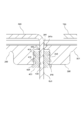
- FIG. 9 is a cross-sectional view of a main part of the film capacitor in a state before the filling resin is filled, showing the periphery of the first through hole according to the embodiment.
- the film capacitor 1 which is an embodiment of the capacitor of the present invention, will be described with reference to the drawings.
- each figure is appropriately marked with front-back, left-right, and up-down directions.
- the direction shown in the figure merely indicates the relative direction of the film capacitor 1, and does not indicate the absolute direction.
- names may be given according to the directions shown in the drawings.
- the film capacitor 1 corresponds to the "capacitor” described in the claims.
- the first through hole 240 and the second through hole 250 correspond to the "through hole” described in the claims.
- the fin portion 410 corresponds to the "first protrusion portion” described in the claims.
- the flange portion 420 corresponds to the "closed portion” described in the claims.
- the rib 430 corresponds to the "second protrusion” described in the claims.
- the first electrode 510 and the second electrode 520 correspond to the "electrode” described in the claims.
- the first bus bar 600 and the second bus bar 700 correspond to the "bus bar” described in the claims.
- the first lower connection terminal portion 650 and the second lower connection terminal portion 750 correspond to the "connection terminal portion” described in the claims.
- FIG. 1A is a perspective view of the film capacitor 1 seen from the front upper side
- FIG. 1B is a perspective view of the film capacitor 1 seen from the front lower part.
- the film capacitor 1 includes a capacitor element unit 100, a case 200 in which the capacitor element unit 100 is housed, a filling resin 300 filled in the case 200, and 2 It comprises two sealing members 400.
- the filling resin 300 is a thermosetting resin such as an epoxy resin, and is injected into the case 200 in which the capacitor element unit 100 is housed in a liquid phase state, and then cured by heating the inside of the case 200. Most of the material buried in the filling resin 300 of the capacitor element unit 100 is protected from moisture and impact.
- the three first upper connection terminal portions 630 and the three second upper connection terminal portions 730 of the capacitor element unit 100 are led out from the opening 200a on the upper surface of the case 200 to the outside.
- the first upper connection terminal portion 630 and the second upper connection terminal portion 730 are arranged side by side in the left-right direction so as to be adjacent to each other.
- the first lower connection terminal portion 650 and the second lower connection terminal portion 750 are led out to the outside through the first through hole 240 and the second through hole 250 provided in the bottom surface portion 201 of the case 200, respectively.
- FIG. 2A is a perspective view of the capacitor element unit 100 seen from the front upper side
- FIG. 2B is a perspective view of the capacitor element unit 100 seen from the rear upper side
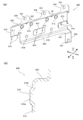
- FIG. 3A is a perspective view of the first bus bar 600 as viewed from the front lower side
- FIG. 3B is a partial side sectional view of the first bus bar 600 showing the periphery of the first protrusion 615.
- FIG. 4A is a perspective view of the second bus bar 700 as viewed from the front lower side
- FIG. 4B is a partial side sectional view of the second bus bar 700 showing the periphery of the second protrusion 715. Is.
- the capacitor element unit 100 includes three capacitor elements 500, a first bus bar 600, a second bus bar 700, and an insulating plate 800.
- the capacitor element 500 is formed by stacking two metallized films on which aluminum is vapor-deposited on a dielectric film, winding or laminating the stacked metallized films, and pressing them in a flat shape.
- the first electrode 510 is formed on one end face by spraying a metal such as zinc
- the second electrode 520 is formed on the other end face by spraying a metal such as zinc.
- the three capacitor elements 500 are arranged so that their peripheral surfaces face each other, and in this state, the first bus bar 600 and the second bus bar 700 are connected to the capacitor elements 500.
- the capacitor element 500 of the present embodiment is formed of a metallized film in which aluminum is vapor-deposited on a dielectric film, but in addition to this, metallization in which other metals such as zinc and magnesium are vapor-deposited. It may be formed of a film. Alternatively, the capacitor element 500 may be formed of a metallized film in which a plurality of metals are vapor-deposited among these metals, or may be formed of a metallized film in which an alloy of these metals is vapor-deposited. ..
- the first bus bar 600 is made of a conductive material, for example, a copper plate, and has a first electrode terminal portion 610, a first upper relay portion 620, three first upper connection terminal portions 630, and a first lower relay portion 640. And the first lower connection terminal portion 650.
- the first bus bar 600 is formed, for example, by appropriately cutting out and bending a single copper plate, the first electrode terminal portion 610, the first upper relay portion 620, the first upper connection terminal portion 630, and the first.
- the lower relay unit 640 and the first lower connection terminal unit 650 are integrated.
- the first electrode terminal portion 610 has a substantially rectangular plate shape and covers the first electrode 510 of each capacitor element 500.
- a notch portion 611 cut out in an substantially L shape is formed at the left end portion, and a substantially rectangular opening portion 612 is formed in the central portion, and is cut out in a substantially U shape.
- the cutout portion 613 is formed at the right end portion.
- a pair of electrode pins 614 are formed on the upper edges of the left and right notches 611, 613 and the opening 612. Each pair of electrode pins 614 is bonded to the first electrode 510 of the corresponding capacitor element 500 by a bonding method such as soldering. As a result, the first bus bar 600 is electrically connected to the capacitor element 500.
- each first protrusion 615 has a substantially flat truncated cone shape, the tip 615a is formed on a circular flat surface, and the peripheral surface 615b has a taper. Further, two circular holes 616 are formed in the lower portion of the first electrode terminal portion 610.
- the first upper relay unit 620 relays between the first electrode terminal unit 610 and the three first upper connection terminal units 630.
- the first upper relay portion 620 extends slightly rearward and then slightly upward from the upper end edge of the first electrode terminal portion 610.
- Two oval holes 621 are formed in the first upper relay portion 620 so as to be arranged in the left-right direction.
- the three first upper connection terminal portions 630 are formed at predetermined intervals on the upper edge portion of the first upper relay portion 620. Each first upper connection terminal portion 630 extends upward from the upper end edge of the first upper relay portion 620, the base end portion expands, and both corner portions of the tip portion have large R's. A circular mounting hole 631 is formed in each first upper connection terminal portion 630.
- the first lower relay unit 640 relays between the first electrode terminal unit 610 and the first lower connection terminal unit 650.
- the first lower relay portion 640 extends rearward from the lower end edge of the first electrode terminal portion 610.
- the first lower relay portion 640 includes a connection portion 641 extending rearward at the right end portion thereof with the same width as the first lower connection terminal portion 650 and connected to the first lower connection terminal portion 650.
- the first lower connection terminal portion 650 extends downward from the tip of the connection portion 641 of the first lower relay portion 640 and has a substantially rectangular plate shape.
- a circular mounting hole 651 is formed in the first lower connection terminal portion 650.
- the second bus bar 700 is made of a conductive material, for example, a copper plate, and has a second electrode terminal portion 710, a second upper relay portion 720, a second upper connection terminal portion 730, and a second lower relay portion 740. Includes the second lower connection terminal portion 750.
- the second bus bar 700 is formed, for example, by appropriately cutting out and bending a single copper plate, and includes these second electrode terminal portions 710, a second upper relay portion 720, and three second upper connection terminal portions 730.
- the second lower relay section 740 and the second lower connection terminal section 750 are integrated.
- the second electrode terminal portion 710 has a substantially rectangular plate shape and covers the second electrode 520 of each capacitor element 500.
- a notch portion 711 cut out in a substantially U shape is formed at the left end portion, and two substantially rectangular openings 712 and 713 are formed in the central portion and the right portion. ..
- a pair of electrode pins 714 are formed on the upper edges of the notch 711 and the two openings 712, 713.
- Each pair of electrode pins 714 is bonded to the second electrode 520 of the corresponding capacitor element 500 by a bonding method such as soldering.
- the second bus bar 700 is electrically connected to the capacitor element 500.
- each second protrusion 715 has a substantially flat truncated cone shape, the tip 715a is formed on a circular flat surface, and the peripheral surface 715b has a taper. Further, two circular holes 716 are formed in each of the upper portion and the lower portion of the second electrode terminal portion 710.
- the second upper relay unit 720 relays between the second electrode terminal unit 710 and the three second upper connection terminal units 730.
- the second upper relay portion 720 extends forward from the upper end edge of the second electrode terminal portion 710 and then slightly upwards.
- two oval holes 721 and four circular holes 722 are formed so as to be arranged in the left-right direction.
- three oval holes 723 are formed in front of the six holes 721 and 722 so as to be arranged in the left-right direction.
- the three second upper connection terminal portions 730 are formed at predetermined intervals on the upper edge portion of the second upper relay portion 720. Each second upper connection terminal portion 730 extends upward from the upper end edge of the second upper relay portion 720, the base end portion expands, and both corner portions of the tip portion have large R's. A circular mounting hole 731 is formed in each second upper connection terminal portion 730.
- the second lower relay section 740 relays between the second electrode terminal section 710 and the second lower connection terminal section 750.
- the second lower relay portion 740 extends forward from the lower end edge of the second electrode terminal portion 710.
- the second lower relay portion 740 includes a connection portion 741 extending rearward at the right end portion thereof with the same width as the second lower connection terminal portion 750 and connected to the second lower connection terminal portion 750.
- the second lower connection terminal portion 750 extends downward from the tip of the connection portion 741 of the second lower relay portion 740 and has a substantially rectangular plate shape.
- a circular mounting hole 751 is formed in the second lower connection terminal portion 750.
- the insulating plate 800 is formed of a resin material such as polyphenylene sulfide (PPS), and has a first upper relay portion 620 of the first bus bar 600, three first upper connection terminal portions 630, and a second upper relay portion of the second bus bar 700. It is interposed between the portions of the 720 and the three second upper connection terminal portions 730 that overlap in the front-rear direction.
- the insulating plate 800 ensures the insulation between the first bus bar 600 and the second bus bar 700.
- the first lower connection terminal portion 650 of the first bus bar 600 and the second lower connection terminal portion 750 of the second bus bar 700 are located at the lower right end.
- FIG. 5A is a perspective view of the case 200 seen from the front upper side
- FIG. 5B is a perspective view of the case 200 seen from the rear upper side
- FIG. 6A is a perspective view of the right side portion of the case 200 as viewed from the front lower side
- FIG. 6B is a case 200 showing the periphery of the first through hole 240 and the second through hole 250. It is a partial front sectional view.
- the case 200 is made of resin, is formed of, for example, polyphenylene sulfide (PPS), has a substantially rectangular parallelepiped box shape long in the left-right direction, and has an upper surface. Open.
- the case 200 includes a bottom surface portion 201 facing the opening 200a on the upper surface, a front side surface portion 202, a rear side surface portion 203, a left side surface portion 204, and a right side surface portion 205 that rise from the bottom surface portion 201 and surround the front, rear, left, and right sides of the bottom surface portion 201, respectively. Consists of.
- the front side surface portion 202 and the rear side surface portion 203 are a pair of side surface portions along the longitudinal direction of the case 200, and the width (dimension in the left-right direction) is relatively large. It is a pair of side surfaces along the lateral direction, and its width (dimensions in the front-rear direction) is relatively small.
- the left side surface portion 204 and the right side surface portion 205 are provided with mounting tabs 210 on the outer wall surface. Insertion holes 211 are formed on the upper side and the lower side of each mounting tab 210. A metal collar 212 is fitted into the insertion hole 211 in order to increase the strength of the hole.
- first ribs 220 and six second ribs 230 protruding from the inner wall surface to the inside of the case 200 in the left-right direction. Formed side by side. That is, the plurality of first ribs 220 and second ribs 230 are arranged so as to be dispersed at predetermined intervals over the entire side surface portions so that the front side surface portions 202 and the rear side surface portions 203 can be reinforced.
- Each first rib 220 and each second rib 230 extend from the vicinity of the bottom surface portion 201 to the vicinity of the opening portion 200a.
- Each of the first rib 220 and each second rib 230 has a substantially rectangular parallelepiped shape that is elongated in the vertical direction and flattened in the front-rear direction.
- the tips 221 and 231 of each first rib 220 and each second rib 230 are elongated rectangular flat surfaces.
- the upper ends (ends on the opening 200a side) 222 and 232 of each first rib 220 and each second rib 230 are inclined away from the opening 200a toward the inside of the case 200.
- the positions of the four first ribs 220 in the central portion correspond to the positions of the four first protrusions 615 of the first bus bar 600.
- the horizontal dimension of these four first ribs 220 is slightly smaller than the diameter (horizontal dimension) of the tip 615a of the first protrusion 615, and the vertical dimension is the first protrusion. It is significantly larger than the diameter (vertical dimension) of the tip 615a of the 615.
- the positions of the four second ribs 230 in the central portion correspond to the positions of the four second protrusions 715 of the second bus bar 700.
- the horizontal dimension of these four second ribs 230 is slightly smaller than the diameter of the tip 715a of the second protrusion 715, and the vertical dimension is the diameter of the tip 715a of the second protrusion 715. It is significantly larger than (vertical dimensions).
- the bottom surface portion 201 has a shape in which the portion near the right end 201a has a slightly deeper bottom than the other portions.
- a substantially square overhanging portion 206 is formed in the portion near the right end, and the wall thickness of the bottom surface portion 201 in the overhanging portion 206 is larger than that of the other portions.
- the first through hole 240 and the second through hole 250 are formed in the overhanging portion 206 so as to be lined up in the left-right direction.
- the first through hole 240 and the second through hole 250 include a first hole 241 and 251 and a second hole 242 and 252 continuous with the first hole 241 and 251.
- the second holes 242 and 252 are larger and longer (deeper) than the first holes 241 and 251.
- the first holes 241 and 251 are located inside the case 200, and the second holes 242 and 252 are located outside the case 200.
- the first holes 241 and 251 each have a shape corresponding to the horizontal cross-sectional shape of the first lower connection terminal portion 650 and the second lower connection terminal portion 750, that is, an elongated rectangular shape.
- the inner wall surfaces of the first holes 241 and 251 are provided with inclinations 241a and 251a so that the holes expand toward the inside of the case 200.
- the diameters of the lower end portions of the first holes 241 and 251 with the smallest openings are the diameters (thickness dimensions, thickness dimensions) of the first lower connection terminal portion 650 and the second lower connection terminal portion 750, respectively. It is slightly larger than the width dimension).
- the second holes 242 and 252 have a shape corresponding to the planar shape of the sealing member 400, that is, an oval shape. On the inner wall surface of the second holes 242 and 252, a draft of the mold for molding the case 200 is slightly formed.
- FIG. 7 (a) and 7 (b) are a perspective view and a plan view of the sealing member 400, respectively, and FIG. 7 (c) is a cross-sectional view taken along the line AA'of FIG. 7 (b).
- the two sealing members 400 are formed of an elastic material, for example, a rubber material such as silicone rubber, and have an oval tubular shape.
- each sealing member 400 an elastically deformable annular fin portion 410 is formed at the tip portion and the intermediate portion so as to go around the outer peripheral surface thereof.
- the fin portion 410 has a shape similar to a right triangle in cross section, and the surface 411 facing the tip direction (upward direction) is inclined while being gently convexly curved, and the base end.
- the surface 412 facing in the direction (downward) is gently concavely curved.
- the height of the fin portion 410 at the tip portion is slightly lower than the height of the fin portion 410 at the intermediate portion in order to match the draft of the second holes 242 and 252 of the case 200.
- each sealing member 400 is formed with a flange portion 420 at the base end portion.
- each sealing member 400 is formed with two elastically deformable annular ribs 430 that orbit the inner peripheral surface thereof.
- Each rib 430 has a semicircular cross section. In the length direction (vertical direction) of the sealing member 400, the rib 430 on the distal end side is located between the two fin portions 410, and the rib 430 on the proximal end side is located between the fin portion 410 and the flange portion 420 in the intermediate portion. Located in. That is, the positions of the two fin portions 410 and the positions of the two ribs 430 are different in the length direction of the sealing member 400.
- the outer diameter of the sealing member 400 including the fin portion 410 is larger than the diameters of the second holes 242 and 252 of the first through hole 240 and the second through hole 250. Further, the inner diameter of the sealing member 400 including the rib 430 is smaller than the diameter (thickness, width) of the first lower connection terminal portion 650 and the second lower connection terminal portion 750.
- FIG. 8A is a side sectional view of the film capacitor 1 in a state before the filling resin 300 is filled
- FIG. 8B is a side sectional view of the film capacitor 1 in a state before the filling resin 300 is filled. It is a top view of the central part.
- FIG. 9 is a cross-sectional view of a main part of the film capacitor 1 in a state before the filling resin 300 is filled, showing the periphery of the first through hole 240.
- the sealing member 400 shows the fin portion 410 and the rib 430 in a state before being deformed.
- the capacitor element unit 100 is housed in the case 200 through the opening 200a on the upper surface of the case 200.
- the first lower connection terminal portion 650 of the first bus bar 600 is passed through the first through hole 240 and led out to the outside
- the second lower connection terminal portion 750 of the second bus bar 700 is the second through hole 250. It is passed through to the outside.
- the first holes 241 and 251 of the first through hole 240 and the second through hole 250 extend toward the inside of the case 200, the first lower connection terminal portion 650 and the first lower connection terminal portion 650 and the first through inside the case 200. 2
- the lower connection terminal portion 750 can be easily inserted into the first through hole 240 and the second through hole 250.
- the positions of the first lower connection terminal portion 650 and the second lower connection terminal portion 750 that have passed through the first through hole 240 and the second through hole 250 are restricted by the first holes 241 and 251.
- the first electrode terminal portion 610 of the first bus bar 600 faces the front side surface portion 202, and the four first projection portions 615 of the first electrode terminal portion 610 At a position closer to the opening 200a than the upper portion of the case 200, that is, the bottom surface portion 201, the case abuts on the four first ribs 220 at the central portion of the front side surface portion 202.
- the second electrode terminal portion 710 of the second bus bar 700 faces the rear side surface portion 203, and the four second projection portions 715 of the second electrode terminal portion 710 are located on the rear side surface portion 203 in the upper part of the case 200. It abuts on the four second ribs 230 in the center.
- the flat surfaces of the tips 221 and 615a of the first rib 220 and the first protrusion 615 are in contact with each other, and the flat surfaces of the tips 231 and 715a of the second rib 230 and the second protrusion 715 are in contact with each other. They come into contact with each other. Therefore, even if the positions of the first rib 220 and the first protrusion 615 or the positions of the second rib 230 and the second protrusion 715 are slightly displaced in the left-right direction, they can be reliably brought into contact with each other.
- the diameters of the tips 615a and 715a of the first protrusion 615 and the second protrusion 715 are the widths of the tips 221 and 231 of the first rib 220 and the second rib 230 (dimensions in the left-right direction).
- the first rib 220 and the first protrusion 615 are combined with each other while suppressing an increase in the amount of resin in the case 200 due to the widening of the width of the first rib 220 and the second rib 230.
- the second rib 230 and the second protrusion 715 can be brought into contact with each other more reliably.
- the upper end portions 222 and 232 of the first rib 220 and the second rib 230, and the lower side of the peripheral surfaces 615b and 715b of the first protrusion 615 and the second protrusion 715, that is, the bottom surface 201 side is the case 200. It is inclined away from the opening 200a toward the inside of the. As a result, when the capacitor element unit 100 is inserted into the case 200 from above, the first protrusion 615 and the second protrusion 715 are less likely to be caught by the upper ends 222 and 232 of the first rib 220 and the second rib 230. .. Therefore, the capacitor element unit 100 can be smoothly housed in the case 200.
- the sealing member 400 is inserted into the first lower connection terminal portion 650 and the second lower connection terminal portion 750 from the outside of the case 200, and the first through hole is inserted. It is inserted into the second holes 242 and 252 of the 240 and the second through hole 250.
- the sealing member 400 is pushed into the second holes 242, 252 until its flange portion 420 abuts on the wall surface around the second holes 242, 252 in the overhanging portion 206 of the case 200, the sealing member 400 is pushed into the second holes 242, 252. Installation of 400 is completed. By confirming that the flange portion 420 is in contact with the wall surface of the overhanging portion 206, it can be confirmed that the sealing member 400 is completely mounted.
- the sealing member 400 is interposed between the outer surface of the first lower connection terminal portion 650 and the inner wall surface of the second hole 242 of the first through hole 240, and is connected to the first lower connection terminal portion 650.
- the space between the first through hole 240 and the hole 240 is sealed.
- the two fin portions 410 on the outer peripheral surface of the sealing member 400 are deformed downward, that is, in the direction opposite to the insertion direction of the sealing member 400 into the first through hole 240, and are deformed so as to shrink inward. It abuts on the inner wall surface of the two holes 242 all around. Each fin portion 410 is in a state of being pressed against the inner wall surface of the second hole 242.
- the two ribs 430 on the inner peripheral surface of the sealing member 400 are deformed so as to shrink inward, and abut on the outer surface of the first lower connection terminal portion 650 on the entire circumference.
- Each rib 430 is in a state of being pressed against the outer surface of the first lower connection terminal portion 650.
- the portion of the inner peripheral surface of the sealing member 400 other than the rib 430 does not come into contact with the outer surface of the first lower connection terminal portion 650. Therefore, the sealing member 400 can be easily inserted into the first lower connection terminal portion 650.
- the length from the tip of the sealing member 400 to the front of the flange portion 420 is shorter than the length of the second hole 242. As a result, a slight gap is formed between the wall surface between the first hole 241 and the second hole 242 of the first through hole 240 and the tip surface of the sealing member 400.
- the sealing member 400 is interposed between the outer surface of the second lower connection terminal portion 750 and the inner wall surface of the second hole 252 of the second through hole 250, and the second lower connection terminal portion 750 and the second penetration are provided.
- the space between the hole 250 and the hole 250 is sealed.
- the two fin portions 410 are deformed and abut against the inner wall surface of the second hole 252 all around, and the two ribs 430 are deformed and abut against the outer surface of the second lower connection terminal portion 750 all around. ..
- a slight gap is formed between the wall surface between the first hole 251 and the second hole 252 of the second through hole 250 and the tip surface of the sealing member 400.
- the fin portion 410 of the sealing member 400 has an inclined surface 411 facing the tip end direction, that is, the insertion direction. Therefore, the resistance generated when the sealing member 400 is inserted into the second holes 242 and 252 becomes smaller, and the sealing member 400 can be easily inserted into the second holes 242 and 252.
- the filled resin 300 in the liquid phase state is injected and stored in the case 200 in which the capacitor element unit 100 is housed through the opening 200a.
- the space between the first lower connection terminal portion 650 and the first through hole 240 is sealed by the sealing member 400, and the space between the second lower connection terminal portion 750 and the second through hole 250 is sealed. It is sealed by the member 400. This prevents the filled resin 300 in the liquid phase state from leaking from the first through hole 240 and the second through hole 250 to the outside of the case 200.
- the fin portion 410 strongly adheres to the inner wall surfaces of the second holes 242 and 252 of the first through hole 240 and the second through hole 250 due to the pressing force (stress) generated by the deformation thereof.
- the space between the sealing member 400 and the inner wall surfaces of the second holes 242 and 252 is strongly closed. Thereby, leakage of the filling resin 300 from between the sealing member 400 and the second holes 242 and 252 can be well prevented.
- the sealing member 400 is in close contact with the sealing member 400 because the rib 430 strongly adheres to the outer surfaces of the first lower connecting terminal portion 650 and the second lower connecting terminal portion 750 due to the pressing force (stress) generated by the deformation thereof.
- the space between the first lower connection terminal portion 650 and the outer surface of the second lower connection terminal portion 750 is strongly closed. Thereby, leakage of the filling resin 300 from between the sealing member 400 and the first lower connection terminal portion 650 and the second lower connection terminal portion 750 can be well prevented.
- the filling resin 300 is moved from the first through hole 240 and the second through hole 250 to the outside of the case 200. Leakage is further prevented.
- the vertical dimension of the first protrusion 615 (the direction in which the opening 200a and the bottom surface 201 are aligned) is smaller than the vertical dimension of the first rib 220, and at the positions of the four first ribs 220 in the central portion. In the vertical direction, a gap is formed between the first electrode terminal portion 610 and the first rib 220 except for the portion where the first rib 220 and the first protrusion 615 are in contact with each other.
- the vertical dimension of the second protrusion 715 is smaller than the vertical dimension of the second rib 230, and at the positions of the four second ribs 230 in the central portion, the second rib 230 and the second rib 230 are located in the vertical direction.
- a gap is formed between the second electrode terminal portion 710 and the second rib 230 except for the portion in contact with the second protrusion 715. Therefore, the filling resin 300 can smoothly move back and forth in the left-right direction at the positions of the first rib 220 and the second rib 230, and is between the front side surface portion 202 and the first electrode terminal portion 610, and the rear side surface portions 203 and the first. It spreads well between the two electrode terminal portions 710.
- the filling resin 300 flowing into the case 200 is circulated through the holes 616, 621 provided in the first bus bar 600 and the holes 716, 721, 722, 723 provided in the second bus bar 700. It is well distributed on the inner side of the capacitor element unit 100, that is, between the first bus bar 600 and the second bus bar 700 and the three capacitor elements 500.
- the case 200 is heated, whereby the filling resin 300 in the case 200 is cured. After that, the cured filling resin 300 is cooled, but at this time, the filling resin 300 may shrink. At this time, stress is generated on the front side surface portion 202, the rear side surface portion 203, the left side surface portion 204, and the right side surface portion 205 of the case 200 due to the filling resin 300 to be contracted to the inside of the case 200.
- the front side surface portion 202 and the rear side surface portion 203 are reinforced by six first ribs 220 and second ribs 230, respectively. Further, the four first ribs 220 and the second ribs 230 in the central portion abut on the first protrusion 615 and the second protrusion 715, so that the front side surface portion 202 and the rear side surface portion 203 are brought into the case 200. It is supported from the inside of the first protrusion 615 and the second protrusion 715. As a result, the warpage of the front side surface portion 202 and the rear side surface portion 203 toward the inside of the case 200 is strongly suppressed.
- the front side surface portion 202 and the rear side surface portion 203 tend to warp on the upper side near the opening 200a, but since the first protrusion 615 and the second protrusion 715 are located at the upper part, the front side surface portion 202 and the rear side surface portion 202 and the rear surface portion 203 are easily warped. The warp of the side surface portion 203 can be effectively suppressed.
- the left side surface portion 204 and the right side surface portion 205 have small dimensions in the front-rear direction and are reinforced by mounting tabs 210 formed on the outer wall surface.
- the left side surface portion 204 and the right side surface portion 205 are warped toward the inside of the case 200 even if the first rib 220 and the second rib 230 and the first protrusion 615 and the second protrusion 715 are not configured. Be prevented.
- the film capacitor 1 is completed as shown in FIGS. 1 (a) and 1 (b).
- the film capacitor 1 is mounted on various external devices such as an inverter device provided in an electric vehicle.
- a pair of external terminals (not shown) corresponding to these connection terminal portions 630 and 730 provided in an external device or the like are connected to the first upper connection terminal portion 630 and the second upper connection terminal portion 730.
- a pair of external terminals (not shown) corresponding to these connection terminal portions 650 and 750 provided in the external device are connected to the first lower connection terminal portion 650 and the second lower connection terminal portion 750.
- the front-back and left-right directions of the film capacitor 1 when mounted on an external device are the directions shown in the present embodiment, that is, the direction in which the opening 200a of the case 200 is in the upward direction and the bottom surface portion 201 is in the downward direction. Is not always the same.
- the film capacitor 1 may be installed in an external device so that the rear side surface portion 203 faces downward.
- a cooler (not shown) is mounted on the outer surface of the rear side surface portion 203. At this time, since the flatness of the rear side surface portion 203 of the film capacitor 1 is increased, the adhesion of the cooler is improved and good cooling performance can be obtained.
- the film capacitor 1 is an annular sealing member interposed between the outer surface of the first lower connection terminal portion 650 (second lower connection terminal portion 750) and the inner wall surface of the first through hole 240 (second through hole 250). It is equipped with 400.
- the sealing member 400 has a deformable annular fin portion 410 on its outer surface.
- the outer diameter of the sealing member 400 including the fin portion 410 is larger than the diameter of the first through hole 240 (second through hole 250), and the fin portion 410 is deformed to form the first through hole 240 (second through hole 250). It abuts on the inner wall surface of the hole 250).
- the space between the first lower connection terminal portion 650 (second lower connection terminal portion 750) and the first through hole 240 (second through hole 250) is sealed by the sealing member 400.
- the filling resin 300 in the liquid phase state is prevented from leaking from the first through hole 240 (second through hole 250) to the outside of the case 200.
- the fin portion 410 strongly closes the space between the sealing member 400 and the inner wall surface of the first through hole 240 (second through hole 250), the sealing member 400 and the first through hole 240 (second through hole 240) are strongly closed. Leakage of the filling resin 300 from between the through hole 250) can be well prevented.
- the sealing member 400 only needs to be attached to the first through hole 240 (second through hole 250), and leakage of the filling resin 300 from the first through hole 240 (second through hole 250) can be easily prevented. ..
- the sealing member 400 abuts on the wall surface around the first through hole 240 (second through hole 250) on the outside of the case 200, and the first through hole 240 (second through hole 250) is in contact with the wall surface.
- the filling resin 300 is further prevented from leaking from the first through hole 240 (second through hole 250) to the outside of the case 200.
- the first through hole 240 (second through hole 250) has a first hole 241 (251) and a second hole 242 (252) continuous with the first hole 241 (251).
- the second hole 242 (252) is larger than the first hole 241 (251), and the sealing member 400 is arranged in the second hole 242 (252).
- the position of the first lower connection terminal portion 650 (second lower connection terminal portion 750) is restricted by the first hole 241 (251), and the first lower connection terminal portion is regulated by the sealing member 400.
- the space between the 650 (second lower connection terminal portion 750) and the second hole 242 (252) can be sealed.
- the film capacitor 1 is configured such that the first hole 241 (251) is located inside the case 200 and the second hole 242 (252) is located outside the case 200.
- the sealing member 400 can be inserted into the second hole 242 (252) from the outside of the case 200, so that the sealing member 400 can be easily attached to the case 200.
- the sealing member 400 has a deformable annular rib 430 on the inner surface thereof.
- the inner diameter of the sealing member 400 including the rib 430 is smaller than the diameter of the first lower connection terminal portion 650 (second lower connection terminal portion 750), and the rib 430 is deformed to form the first lower connection terminal portion 650 (the first lower connection terminal portion 650). It abuts on the outer surface of the second lower connection terminal portion 750).
- the rib 430 strongly closes the space between the sealing member 400 and the outer surface of the first lower connecting terminal portion 650 (second lower connecting terminal portion 750), so that the sealing member 400 and the first Leakage of the filling resin 300 from the lower connection terminal portion 650 (second lower connection terminal portion 750) can be well prevented.
- the film capacitor 1 is configured such that the position of the fin portion 410 and the position of the rib 430 are different in the length direction of the sealing member 400.
- the stress applied to the inner wall surface of the first through hole 240 (second through hole 250) by the fin portion 410 and the rib 430 cause the outer surface of the first lower connection terminal portion 650 (second lower connection terminal portion 750). Since the position of the stress applied to the sealing member 400 can be dispersed in the length direction of the sealing member 400, the sealing member 400 can be easily inserted into the first through hole 240 (second through hole 250).
- two fin portions 410 having a shape similar to a right triangle in cross section are formed on the outer peripheral surface of the sealing member 400.
- the shape of the fin portion 410 is not limited to the above shape, and can be appropriately changed, and the number of fin portions 410 can also be appropriately changed according to the length of the sealing member 400 and the like.
- two ribs 430 having a semicircular cross section are formed on the inner peripheral surface of the sealing member 400.
- the shape of the rib 430 is not limited to the above shape, and can be appropriately changed, and the number of ribs 430 can also be appropriately changed according to the length of the sealing member 400 and the like.
- the sealing member 400 is not provided with the rib 430 on the inner peripheral surface, and the entire inner peripheral surface is configured to be in close contact with the outer surface of the first lower connection terminal portion 650 (second lower connection terminal portion 750). good.
- the sealing member 400 is provided with the flange portion 420.
- the sealing member 400 may be configured so that the flange portion 420 is not provided.
- the first through hole 240 and the second through hole 250 are composed of the first holes 241 and 251 and the second through holes 242 and 252.
- the first through hole 240 and the second through hole 250 may be configured such that the first through holes 241 and 251 are absent and the second through holes 242 and 252 are connected to the inside of the case 200.
- it is preferable that the length of the sealing member 400 is changed according to the length of the second holes 242 and 252 being changed.
- the first through hole 240 and the second through hole 250 are provided in the bottom surface portion 201 of the case 200.
- the first through hole 240 and the second through hole 250 may be provided in any of the front side surface portion 202, the rear side surface portion 203, the left side surface portion 204, and the right side surface portion 205 of the case 200.
- a first through hole and a second through hole may be provided on a plurality of side surface portions of the case 200, and a connection terminal portion corresponding to the through hole may be provided on the first bus bar 600 and the second bus bar 700. ..
- the capacitor element unit 100 includes three capacitor elements 500.
- the number of the capacitor elements 500 can be appropriately changed, including the case where the number of the capacitor elements is one.
- the capacitor element 500 is formed by stacking two metallized films on which aluminum is vapor-deposited on a dielectric film, and winding or laminating the laminated metallized films.
- these capacitor elements 500 may be formed by superimposing a metallized film in which aluminum is vapor-deposited on both sides of a dielectric film and an insulating film, and winding or laminating them.
- the film capacitor 1 is mentioned as an example of the capacitor of the present invention.
- the present invention can also be applied to capacitors other than the film capacitor 1.
- the terms such as “upward” and “downward” indicate the relative direction depending only on the relative positional relationship of the constituent members, and indicate the vertical direction and the horizontal direction. It does not indicate the absolute direction such as.
- the present invention is useful for capacitors used in various electronic devices, electrical devices, industrial devices, electrical components of vehicles, and the like.
Landscapes
- Engineering & Computer Science (AREA)
- Power Engineering (AREA)
- Microelectronics & Electronic Packaging (AREA)
- Manufacturing & Machinery (AREA)
- Fixed Capacitors And Capacitor Manufacturing Machines (AREA)
Priority Applications (2)
| Application Number | Priority Date | Filing Date | Title |
|---|---|---|---|
| JP2022535009A JP7664556B2 (ja) | 2020-07-07 | 2021-06-23 | コンデンサ |
| CN202180034670.3A CN115552558A (zh) | 2020-07-07 | 2021-06-23 | 电容器 |
Applications Claiming Priority (2)
| Application Number | Priority Date | Filing Date | Title |
|---|---|---|---|
| JP2020-117162 | 2020-07-07 | ||
| JP2020117162 | 2020-07-07 |
Publications (1)
| Publication Number | Publication Date |
|---|---|
| WO2022009680A1 true WO2022009680A1 (ja) | 2022-01-13 |
Family
ID=79552998
Family Applications (1)
| Application Number | Title | Priority Date | Filing Date |
|---|---|---|---|
| PCT/JP2021/023817 Ceased WO2022009680A1 (ja) | 2020-07-07 | 2021-06-23 | コンデンサ |
Country Status (3)
| Country | Link |
|---|---|
| JP (1) | JP7664556B2 (https=) |
| CN (1) | CN115552558A (https=) |
| WO (1) | WO2022009680A1 (https=) |
Citations (5)
| Publication number | Priority date | Publication date | Assignee | Title |
|---|---|---|---|---|
| JPS5790515U (https=) * | 1980-11-22 | 1982-06-03 | ||
| JPS5897826U (ja) * | 1981-12-24 | 1983-07-02 | 松下電器産業株式会社 | コンデンサ用蓋 |
| JP2004281226A (ja) * | 2003-03-14 | 2004-10-07 | Yuasa Corp | 密閉型蓄電池 |
| JP2016058688A (ja) * | 2014-09-12 | 2016-04-21 | 株式会社豊田自動織機 | コンデンサモジュールおよびコンデンサモジュールの製造方法 |
| WO2019131192A1 (ja) * | 2017-12-28 | 2019-07-04 | パナソニックIpマネジメント株式会社 | コンデンサ |
Family Cites Families (5)
| Publication number | Priority date | Publication date | Assignee | Title |
|---|---|---|---|---|
| JP4745864B2 (ja) * | 2006-02-28 | 2011-08-10 | 新電元工業株式会社 | 電解コンデンサ装置 |
| CA2912790C (en) * | 2013-06-14 | 2016-08-16 | Abb Technology Ag | Terminal bushing sealing unit for use in sound attenuation casing |
| JP6915548B2 (ja) * | 2015-12-28 | 2021-08-04 | 株式会社Gsユアサ | 封止部材、蓄電素子及び蓄電素子の製造方法 |
| JP6292243B2 (ja) * | 2016-02-16 | 2018-03-14 | トヨタ自動車株式会社 | 密閉型電池 |
| CN207587539U (zh) * | 2017-11-10 | 2018-07-06 | 佛山市泰豪包装实业有限公司 | 一种干式网状防爆金属化薄膜电容器 |
-
2021
- 2021-06-23 JP JP2022535009A patent/JP7664556B2/ja active Active
- 2021-06-23 WO PCT/JP2021/023817 patent/WO2022009680A1/ja not_active Ceased
- 2021-06-23 CN CN202180034670.3A patent/CN115552558A/zh active Pending
Patent Citations (5)
| Publication number | Priority date | Publication date | Assignee | Title |
|---|---|---|---|---|
| JPS5790515U (https=) * | 1980-11-22 | 1982-06-03 | ||
| JPS5897826U (ja) * | 1981-12-24 | 1983-07-02 | 松下電器産業株式会社 | コンデンサ用蓋 |
| JP2004281226A (ja) * | 2003-03-14 | 2004-10-07 | Yuasa Corp | 密閉型蓄電池 |
| JP2016058688A (ja) * | 2014-09-12 | 2016-04-21 | 株式会社豊田自動織機 | コンデンサモジュールおよびコンデンサモジュールの製造方法 |
| WO2019131192A1 (ja) * | 2017-12-28 | 2019-07-04 | パナソニックIpマネジメント株式会社 | コンデンサ |
Also Published As
| Publication number | Publication date |
|---|---|
| CN115552558A (zh) | 2022-12-30 |
| JP7664556B2 (ja) | 2025-04-18 |
| JPWO2022009680A1 (https=) | 2022-01-13 |
Similar Documents
| Publication | Publication Date | Title |
|---|---|---|
| JP4114497B2 (ja) | 回路構成体用ケース及び回路構成体の製造方法 | |
| JP6425024B2 (ja) | コンデンサおよびインバータ | |
| US11232905B2 (en) | Capacitor | |
| CN114072889B (zh) | 电容器 | |
| JP7050229B2 (ja) | コンデンサ | |
| US11404212B2 (en) | Capacitor | |
| CN113196427B (zh) | 电容器 | |
| JP2020017649A (ja) | カバー、該カバーを備えた回路基板ユニット、及び、前記カバーの製造方法 | |
| WO2022009680A1 (ja) | コンデンサ | |
| JPWO2019181109A1 (ja) | コンデンサ | |
| JP4940665B2 (ja) | ケースモールド型コンデンサ | |
| WO2022009681A1 (ja) | コンデンサ | |
| JP6832514B2 (ja) | コンデンサおよびコンデンサの製造方法 | |
| US11452228B2 (en) | Driver | |
| JP4197970B2 (ja) | 配電ユニット及びこの配電ユニットを含む電気接続箱 | |
| CN116157882B (zh) | 电容器 | |
| JP7535699B2 (ja) | コンデンサの製造方法 | |
| JP7634209B2 (ja) | コンデンサ | |
| JP7365679B2 (ja) | コンデンサ | |
| JP5293156B2 (ja) | 電気接続箱 | |
| WO2021085107A1 (ja) | コンデンサ |
Legal Events
| Date | Code | Title | Description |
|---|---|---|---|
| 121 | Ep: the epo has been informed by wipo that ep was designated in this application |
Ref document number: 21837400 Country of ref document: EP Kind code of ref document: A1 |
|
| ENP | Entry into the national phase |
Ref document number: 2022535009 Country of ref document: JP Kind code of ref document: A |
|
| NENP | Non-entry into the national phase |
Ref country code: DE |
|
| 122 | Ep: pct application non-entry in european phase |
Ref document number: 21837400 Country of ref document: EP Kind code of ref document: A1 |