WO2022009487A1 - クリップ構造及びピン部材 - Google Patents
クリップ構造及びピン部材 Download PDFInfo
- Publication number
- WO2022009487A1 WO2022009487A1 PCT/JP2021/013253 JP2021013253W WO2022009487A1 WO 2022009487 A1 WO2022009487 A1 WO 2022009487A1 JP 2021013253 W JP2021013253 W JP 2021013253W WO 2022009487 A1 WO2022009487 A1 WO 2022009487A1
- Authority
- WO
- WIPO (PCT)
- Prior art keywords
- protrusion
- leg
- clip structure
- pin member
- pedestal
- Prior art date
- Legal status (The legal status is an assumption and is not a legal conclusion. Google has not performed a legal analysis and makes no representation as to the accuracy of the status listed.)
- Ceased
Links
Images




Classifications
-
- F—MECHANICAL ENGINEERING; LIGHTING; HEATING; WEAPONS; BLASTING
- F16—ENGINEERING ELEMENTS AND UNITS; GENERAL MEASURES FOR PRODUCING AND MAINTAINING EFFECTIVE FUNCTIONING OF MACHINES OR INSTALLATIONS; THERMAL INSULATION IN GENERAL
- F16B—DEVICES FOR FASTENING OR SECURING CONSTRUCTIONAL ELEMENTS OR MACHINE PARTS TOGETHER, e.g. NAILS, BOLTS, CIRCLIPS, CLAMPS, CLIPS OR WEDGES; JOINTS OR JOINTING
- F16B19/00—Bolts without screw-thread; Pins, including deformable elements; Rivets
- F16B19/04—Rivets; Spigots or the like fastened by riveting
- F16B19/08—Hollow rivets; Multi-part rivets
- F16B19/10—Hollow rivets; Multi-part rivets fastened by expanding mechanically
- F16B19/1027—Multi-part rivets
- F16B19/1036—Blind rivets
- F16B19/1081—Blind rivets fastened by a drive-pin
-
- F—MECHANICAL ENGINEERING; LIGHTING; HEATING; WEAPONS; BLASTING
- F16—ENGINEERING ELEMENTS AND UNITS; GENERAL MEASURES FOR PRODUCING AND MAINTAINING EFFECTIVE FUNCTIONING OF MACHINES OR INSTALLATIONS; THERMAL INSULATION IN GENERAL
- F16B—DEVICES FOR FASTENING OR SECURING CONSTRUCTIONAL ELEMENTS OR MACHINE PARTS TOGETHER, e.g. NAILS, BOLTS, CIRCLIPS, CLAMPS, CLIPS OR WEDGES; JOINTS OR JOINTING
- F16B19/00—Bolts without screw-thread; Pins, including deformable elements; Rivets
- F16B19/04—Rivets; Spigots or the like fastened by riveting
- F16B19/08—Hollow rivets; Multi-part rivets
- F16B19/10—Hollow rivets; Multi-part rivets fastened by expanding mechanically
Definitions
- the present invention relates to a clip structure and a pin member to be attached to the attached member.
- the bumper retainer (glomet) moves in a direction that deviates from the body due to the load or external force of the bumper, the force acts in the direction of shearing the pin, the pin tilts, and the flange deforms.
- the present invention has been proposed in view of such circumstances. That is, it is an object of the present invention to provide a clip structure and a pin member having a high shearing force.
- a leg portion to be inserted into the attached member is formed on a pedestal portion facing the attached member, and the leg portion is arranged around the pedestal portion.
- It is a clip structure composed of a grommet member having a hole to be inserted and a pin member having a shaft portion inserted into the hole to be inserted and engaging with the leg portion, and the grommet member is the grommet member. It has a protrusion that protrudes toward the side opposite to the leg with respect to the pedestal, and the pin member meets the protrusion in a direction that intersects the shaft on the protrusion side of the pedestal. It is characterized by having a receiving portion to hit.
- the clip structure according to the present invention has a concave groove shape in which the shaft portion and the receiving portion are connected to each other, the flange portion is connected to the receiving portion, and the protrusion portion is inserted between the receiving portion and the flange portion. It is characterized by being formed in.
- the clip structure according to the present invention is characterized in that the flange portion has a thin-walled portion that is pressed against the pedestal portion.
- the clip structure according to the present invention is characterized in that the leg portion has a rib that hits the edge of a hole of the attached member.
- the clip structure according to the present invention is characterized in that the protrusion is formed in an annular shape at the edge of the inserted hole, and the receiving portion is formed in an annular shape on an extension of the shaft portion.
- the pin member according to the present invention is a grommet in which a leg portion to be inserted into the attached member is formed on a pedestal portion facing the attached member and an inserted hole is formed in which the leg portion is arranged around the pin member.
- a pin member that engages with a member and is an extension of the shaft portion that is inserted into the insertion hole and engages with the leg portion and on the side opposite to the leg portion with respect to the pedestal portion.
- An annular concave groove portion that is depressed on the opposite side of the shaft portion and into which a part of the grommet member is inserted, a receiving portion that is connected to the extension of the shaft portion and is a part of the concave groove portion, and the above. It is characterized by having a thin-walled portion connected to the concave groove portion and pressed against the pedestal portion.
- the grommet member has a protrusion that protrudes from the pedestal portion toward the side opposite to the leg portion, and the pin member intersects the shaft portion on the protrusion side of the pedestal portion. It has a receiving part that hits the protrusion in the direction of Even if some force acts on the grommet member in the direction that the grommet member deviates from the mounted member from the direction that intersects the shaft portion of the pin member, the tip of the direction in which the pin member tends to tilt. There is a protrusion of the grommet member, and the receiving portion of the pin member hits the protrusion to prevent the pin member from tilting. That is, it can be said that the present invention has a high shearing force.
- the clip structure according to the present invention is formed in a concave groove shape in which a shaft portion and a receiving portion are connected, a flange portion is connected to the receiving portion, and a protrusion is inserted between the receiving portion and the flange portion. That is, the protrusion of the grommet member is inserted into the concave groove-shaped portion of the pin member. In this state, even if some force acts in the direction in which the grommet member deviates from the attached member, the pin member in which the protrusion of the grommet member is inserted into the concave groove-shaped portion is prevented from tilting. Will be done. That is, it can be said that the present invention has a high shearing force.
- the clip structure according to the present invention has a thin-walled portion in which the flange portion is pressed against the pedestal portion. That is, since the pin member is prevented from tilting, the flange is not deformed, and the flange portion is pressed against the pedestal portion of the grommet member while covering the protrusion. Therefore, the present invention can realize watertightness.
- the legs have ribs that hit the edges of the holes of the attached member. That is, since the rigidity of the leg portion is increased by the rib, the grommet member is less likely to shift. Further, even when some force acts in the direction in which the grommet member deviates from the attached member, the rib of the leg portion of the grommet member hits the edge of the hole of the attached member, so that the grommet member can be formed. It is hard to shift.
- the protrusion is formed in an annular shape at the edge of the hole to be inserted, and the receiving portion is formed in an annular shape on the extension of the shaft portion.
- the receiving portion of the pin member and the protruding portion of the grommet member are in contact with each other on the entire peripheral surface to be firm, and a high shearing force is realized.
- the protrusion is on the edge of the inserted hole and the receiving portion is on the shaft portion of the pin member, the protrusion and the receiving portion are formed at a position away from the inserted hole and the shaft portion. In comparison, the pin member is prevented from tilting. That is, it can be said that the present invention has a high shearing force.
- the pin member according to the present invention is recessed on the side opposite to the leg portion with respect to the shaft portion inserted into the insertion hole and engaged with the leg portion, and on the side opposite to the shaft portion on the extension of the shaft portion.
- An annular concave groove portion into which a part of the grommet member is inserted, a receiving portion connected to the extension of the shaft portion and a part of the concave groove portion, and a thin wall portion connected to the concave groove portion and pressed against the pedestal portion. Has a part. Therefore, the pin member has the same effect as the clip structure described above.
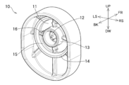
- FIG. 1 is a perspective view of the grommet member in the clip structure according to the embodiment of the present invention as viewed from the side to be inserted.
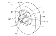
- FIG. 2 is a perspective view of the grommet member in the clip structure according to the embodiment of the present invention as viewed from the leg side.
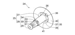
- FIG. 3 is a perspective view of the pin member in the clip structure according to the embodiment of the present invention as viewed from the flange portion side.
- FIG. 4 is a perspective view of the pin member in the clip structure according to the embodiment of the present invention as viewed from the shaft portion side.
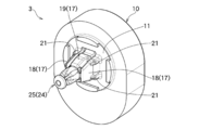
- FIG. 5 is a perspective view seen from the side where the pin member is inserted in the clip structure according to the embodiment of the present invention.
- FIG. 6 is a perspective view seen from the side in which the pin member is inserted in the clip structure according to the embodiment of the present invention.
- FIG. 7 is a rear view showing the side on which the pin member is inserted in the clip structure according to the embodiment of the present invention.
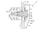
- FIG. 8 is a cross-sectional view taken along the line VIII-VIII in FIG. 7, which is a cross-sectional view of the clip structure according to the embodiment of the present invention.
- FIG. 9 is a cross-sectional view taken along the line IX-IX in FIG. 7, which is a cross-sectional view of the clip structure according to the embodiment of the present invention.
- FIGS. 1 and 2 show the grommet member 10 constituting the clip structure 3
- FIGS. 3 and 4 show the pin member 24 constituting the clip structure 3.
- 5 and 6 show the clip structure 3
- FIGS. 7, 8 and 9 show the appearance and cross section of the clip structure 3 attached to the attached member 1.
- the clip structure 3 has a pin member 24 attached to the grommet member 10, and FIGS. 7, 8 and 6.
- the clip structure 3 is attached to the attached member 1.
- the clip structure 3 is applied to, for example, a bumper retainer or the like used when a bumper is attached to the body of an automobile (the automobile, the body, the bumper and the bumper retainer are not shown). That is, the attached member 1 is formed on, for example, the body of an automobile, and the grommet member 10 is formed on, for example, a bumper retainer or the like. A bumper is attached to the bumper retainer, and in this state, the bumper retainer is attached to the body, so that the bumper is attached to the body.
- the present embodiment has a single clip structure 3, the number of clip structures 3 formed on the bumper retainer is arbitrary.
- the lower side of the insertion direction is the front (Front), the upper side is the rear (Back), and the directions orthogonal to the insertion direction are upward and downward (Up, Down), left and right (Left). Side, Right Side) (see FIGS. 1 and 3).
- the grommet member 10 has a pedestal portion 11 facing the body which is the mounted member 1, and the pedestal portion 11 is formed with an inserted hole 12 into which the pin member 24 is inserted. Has been done.
- a protrusion 13 is formed on the peripheral edge of the insertion hole 12.
- the protrusion 13 has an annular shape or a cylindrical shape centered on the hole 12 to be inserted, and protrudes rearward.
- a wall portion 14 is formed around the protrusion portion 13.
- the wall portion 14 has an annular shape or a cylindrical shape coaxial with the protrusion portion 13 and projects rearward. That is, the pedestal portion 11 is recessed with respect to the height of the wall portion 14.
- a step portion 15 is formed at the connecting portion between the pedestal portion 11 and the wall portion 14.
- the step portion 15 is formed in an annular shape along the wall portion 14.
- a plurality of step pieces 16 are formed between the protrusion portion 13 and the step portion 15.
- the step pieces 16 are formed radially around the protrusions 13 and are arranged at substantially equal intervals in the circumferential direction of the protrusions 13.
- a plurality of leg portions 17 are formed on the peripheral edge of the inserted hole 12.
- the legs 17 are substantially plate-shaped and project forward.
- the leg portions 17 are adjacent to a pair of first leg portions 18 facing each other on the left and right sides with the inserted hole 12 as the center, and are adjacent to the first leg portion 18 and are vertically and vertically centered on the inserted hole 12. It is composed of a pair of second legs 19 facing each other.
- a rib 21 is formed on the outer surface of the base portion 20 which is a portion of the first leg portion 18 connected to the pedestal portion 11.
- the ribs 21 are formed in two places and are arranged at the upper and lower ends of the base 20.
- a raised portion 22 is formed on the inner surface of the second leg portion 19 (see FIG. 8).
- the tip portions of the legs 18 and 19 are formed with a locking piece 23 projecting inward with the legs 18 and 19 facing each other.
- the locking piece 23 of the second leg portion 19 is connected to the raised portion 22.
- the pin member 24 includes a shaft portion 25 inserted into the inserted hole 12 of the grommet member 10 and a receiving portion 26 connected to the extension of the shaft portion 25. It has a flange portion 35 that is connected to the receiving portion 26 and attached to the pedestal portion 11.
- the shaft portion 25 has a substantially hollow cylindrical shape or a columnar shape.
- the shaft portion 25 has an intermediate portion 27 extending forward from the receiving portion 26 and a front end locking portion 28 extending forward from the intermediate portion 27.
- the front end locking portion 28 has a front end portion 29 which is a front end, a temporary fixing portion 30 extending rearward from the front end portion 29, and a locked groove portion 34 connected to the rear of the temporary fixing portion 30. ing.
- the front end portion 29 has a disk shape smaller than the flange portion 35, and the temporary fixing portion 30 is connected to the center thereof.
- the temporary fixing portion 30 is formed with a temporary fixing groove portion 31, an inclined surface 32 that widens toward the side toward the rear, and a plurality of partition portions 33 that project laterally.
- the partition portions 33 extend from the front end portion 29 to the inclined surface 32, and are arranged at substantially equal intervals in the circumferential direction of the shaft portion 25. Therefore, the temporary fixing groove portion 31 and the inclined surface 32 are separated by the partition portion 33.
- the locked groove portion 34 is recessed toward the center of the shaft portion 25 and is divided at the same interval as the partition portion 33.
- the intermediate portion 27 extending from the rear of the locked groove portion 34 has a cylindrical shape or a cylindrical shape without unevenness, and the receiving portion 26 has an annular shape or a cylindrical shape.
- the flange portion 35 has a top portion 37 which is a circular flat plate, an annular or cylindrical covering portion 39 protruding forward from the peripheral edge of the top portion 37, and an annular shape protruding outward from the front end of the covering portion 39. It has a thin-walled portion 40 of.
- An insertion hole 38 into which a tool or the like (not shown) is inserted is formed on the rear surface of the top portion 37.
- a receiving portion 26 is connected to the center of the front surface of the top portion 37.
- the receiving portion 26 has an annular shape or a cylindrical shape, and is arranged facing the inside of the covering portion 39.
- the receiving portion 26 and the covering portion 39 are concentric circles centered on the shaft portion 25, and a concave groove portion 41 having a concave groove shape is formed in a space surrounded by the receiving portion 26, the covering portion 39, and the top portion 37. ing. That is, the concave groove portion 41 is an annular shape having the receiving portion 26 as a part, and is recessed on the extension of the shaft portion 25 on the side opposite to the direction in which the shaft portion 25 extends.
- the thin-walled portion 40 is thinner than the top portion 37 and the covering portion 39, and easily bends.
- an inclined projecting piece 36 that protrudes forward and is inclined in the circumferential direction of the thin-walled portion 40 is formed in the vicinity of the portion connected to the covering portion 39.
- the inclined projecting pieces 36 are formed at two locations and are arranged laterally with respect to the shaft portion 25. In other words, the inclined projecting piece 36 is located at zero and 180 degrees on the circumference of the thin wall portion 40.
- the grommet member 10 and the pin member 24 are combined.
- the shaft portion 25 of the pin member 24 is inserted into the inserted hole 12 of the grommet member 10 and engages with the leg portions 18 and 19 of the grommet member 10.
- the process of engaging the pin member 24 and the grommet member 10 will be described with reference to the drawings.
- the legs 18 and 19 of the grommet member 10 are inserted into the mounted holes 2 formed in the mounted member 1.
- the rib 21 of the first leg portion 18 hits the edge inside the mounted hole 2.
- the shaft portion 25 of the pin member 24 is inserted into the inserted hole 12 of the grommet member 10.
- the front end portion 29 of the shaft portion 25 that has passed through the insertion hole 12 hits the raised portion 22 of the second leg portion 19 and advances while pushing the second leg portion 19 apart, and the second leg portion 19 bends and opens outward.
- the front end portion 29 that has passed through the raised portion 22 hits the locking piece 23 of the first leg portion 18 and advances while pushing the first leg portion 18 apart, and the first leg portion 18 bends and opens outward.
- the temporary fixing groove portion 31 of the shaft portion 25 faces the raised portion 22, so that the second leg portion 19 returns to the original state and the raised portion 22 returns to the temporary fixing groove portion 31. Is placed in.
- the first leg 18 also returns to its original state.
- the locking piece 23 is arranged in the temporary fixing groove portion 31. In this state, the pin member 24 is temporarily fixed to the grommet member 10.
- the inclined surface 32 of the pin member 24 hits the raised portion 22 and advances while expanding the second leg portion 19, and the second leg portion 19 bends and opens outward.
- the inclined surface 32 rubs against the raised portion 22 and hits the locking piece 23 to move forward while pushing the legs 18 and 19 apart, and the legs 18 and 19 bend and open outward.
- the locked groove portion 34 faces the locking piece 23, so that the legs 18 and 19 return to their original states and the locking piece 23 is locked in the locked groove portion. It is arranged at 34. In this state, the pin member 24 is engaged with the grommet member 10.
- the protrusion 13 of the grommet member 10 is inserted into the concave groove portion 41 of the pin member 24.
- the receiving portion 26 faces the protrusion 13 at the rear side of the pedestal portion 11 on the protrusion 13 side and in the direction intersecting the shaft portion 25.
- the flange portion 35 covers the protrusion portion 13. That is, the receiving portion 26, the covering portion 39, and the top portion 37 cover the protruding portion 13, and the tip of the thin-walled portion 40 is pressed against the stepped portion 15 of the grommet member 10 and bends, whereby the thin-walled portion 40 is formed. It is pressed against the pedestal portion 11 and the rear surface side of the pedestal portion 11 becomes watertight.
- the inclined projecting piece 36 of the flange portion 35 is arranged between the step pieces 16 in the grommet member 10.
- the peripheral edge of the inserted hole 12 of the grommet member 10 is an annular or cylindrical shape centered on the inserted hole 12 from the side opposite to the legs 18 and 19 with respect to the pedestal portion 11.
- the protrusion 13 is protruding.
- the pin member 24 is an extension of the shaft portion 25, and an annular or cylindrical receiving portion 26 is connected between the intermediate portion 27 of the shaft portion 25 and the flange portion 35, and this receiving portion is connected. It has an annular recessed groove 41 having 26 as a part.
- the protrusion 13 is inserted into the concave groove portion 41 behind the pedestal portion 11, and in the concave groove portion 41, the receiving portion 26 is the pedestal portion. Behind the eleven, the side surface faces the protrusion 13.
- the hole 12 to be inserted becomes a cylindrical hole that is pseudo-extended rearward from the pedestal portion 11 by the protrusion 13, and the cover of this cylinder.
- the shaft portion 25 and the receiving portion 26 of the pin member 24 are inserted into the insertion hole 12.
- annular or cylindrical receiving portion 26 and the annular or cylindrical protrusion 13 are in contact with each other on the entire peripheral surface and are firm, and a high shearing force is realized.
- the flange portion 35 of the pin member 24 includes a top portion 37 which is a circular flat plate connected to the receiving portion 26, and an annular or cylindrical covering portion 39 protruding forward from the peripheral edge of the top portion 37. It has an annular thin-walled portion 40 that protrudes outward from the front end of the covering portion 39.
- the flange portion 35 covers the protrusion 13 and the tip of the thin-walled portion 40 is pressed against the step portion 15 of the grommet member 10 to bend.
- the thin portion 40 is pressed against the pedestal portion 11. Therefore, watertightness can be realized on the rear surface side of the pedestal portion 11. Further, since the pin member 24 is prevented from being tilted, the flange portion 35 is not deformed and the watertightness can be maintained.
- the base 20 of the first leg 18 has ribs 21 formed on the outer surface thereof. That is, since the rigidity of the first leg portion 18 is increased by the rib 21, the grommet member 10 is less likely to shift. Further, when the legs 18 and 19 of the grommet member 10 are inserted into the mounted holes 2 of the mounted member 1, the ribs 21 hit the edges inside the mounted holes 2. With this configuration, even when some force F acts on the grommet member 10 from the side in the direction in which the grommet member 10 deviates from the mounted member 1, the rib is formed at the edge of the mounted hole 2. By hitting 21, the grommet member 10 is hard to shift. That is, it can be said that this embodiment has a high shearing force.
- the ribs are formed only at the base of the second leg. In another embodiment, ribs are formed at the base of the first leg and the base of the second leg, respectively. In other embodiments, the shape, number, and position of the ribs are arbitrary at the base.
- the protrusion is not a continuous ring, but a plurality of protrusions arranged in a ring. In another embodiment, the protrusion of the grommet member and the receiving portion of the pin member are formed at positions laterally separated from the insertion hole of the grommet member and the shaft portion of the pin member. In other embodiments, the pin member does not have a flange portion.
- the present invention is not limited to the above-described embodiments.
- the present invention can be modified in various ways as long as it does not deviate from the matters described in the claims.
- the present invention is also used, for example, in vehicles such as automobiles, aircraft, and ships.
- Attached member 1 Attached member 2 Attached hole 3 Clip structure 10 Grommet member 11 Pedestal 12 Inserted hole 13 Protrusion 14 Wall 15 Step 16 Step piece 17 Leg 18 First leg 19 Second leg 20 Base 21 Rib 22 Raised part 23 Locking piece 24 Pin member 25 Shaft part 26 Receiving part 27 Intermediate part 28 Front end locking part 29 Front end part 30 Temporary fixing part 31 Temporary fixing groove part 32 Inclined surface 33 Partition part 34 Locked groove part 35 Flange part 36 Inclined projectile 37 Top 38 Insertion hole 39 Cover 40 Thin wall 41 Concave groove F force
Landscapes
- Engineering & Computer Science (AREA)
- General Engineering & Computer Science (AREA)
- Mechanical Engineering (AREA)
- Insertion Pins And Rivets (AREA)
- Snaps, Bayonet Connections, Set Pins, And Snap Rings (AREA)
Abstract
剪断力が高いクリップ構造及びピン部材を提供する。グロメット部材10は、被挿入孔12の周縁であって、台座部11に対して各脚部18,19と反対側から、被挿入孔12を中心とした円環状又は円筒状の突部13が突出し、一方で、ピン部材24は、軸部25の延長上であって、軸部25の中間部27とフランジ部35との間に、円環状又は円筒状の受部26が連接され、この受部26を一部とする環状の凹溝部41を有している。突部13は、台座部11よりも後方で凹溝部41に挿入され、この凹溝部41において、受部26は、台座部11よりも後方において、側面が突部13と対面している。
Description
本発明は、被取付部材に取り付けられるクリップ構造及びピン部材に関するものである。
従来、自動車等のボディにバンパーを取り付けるために用いられる構造として、例えば、下記特許文献1に記載されたグロメットとピンとから成るクリップがある(以下、「文献公知発明」と記す。)。この文献公知発明では、バンパーリテーナーの一部に形成されたグロメットに、ボディに挿入される複数の脚が形成され、この脚同士の中央に、脚を開かせるためにピンが挿入される孔が形成されている。ピンの頭部には、肉薄のフランジが形成され、このフランジがグロメットに圧接することで、文献公知発明は防水機能を発揮する。
しかし、仮に、バンパーの荷重や外力によって、バンパーリテーナー(グロメット)がボディに対してズレる方向に動いた場合、ピンを剪断する方向に力が作用してピンが傾き、フランジが変形する。
本発明は、この様な実情に鑑みて提案されたものである。すなわち、剪断力が高いクリップ構造及びピン部材の提供を目的とする。
上記目的を達成するために、本発明に係るクリップ構造は、被取付部材と対峙する台座部に、前記被取付部材に挿入される脚部が形成されると共に当該脚部が周囲に配置された被挿入孔が形成されたグロメット部材と、前記被挿入孔に挿入されて前記脚部と係合する軸部を有するピン部材と、から構成されたクリップ構造であって、前記グロメット部材が、前記台座部に対して、前記脚部と反対側に向けて突出した突部を有し、前記ピン部材が、前記台座部よりも前記突部側で前記軸部と交差する方向において前記突部と当たる受部を有する、ことを特徴とする。
本発明に係るクリップ構造は、前記軸部と前記受部とが連接され、前記受部にフランジ部が連接され、前記受部と前記フランジ部とで、前記突部が挿入される凹溝状に形成された、ことを特徴とする。
本発明に係るクリップ構造は、前記フランジ部が、前記台座部に圧接される薄肉部を有する、ことを特徴とする。
本発明に係るクリップ構造は、前記脚部が、前記被取付部材の孔の縁に当たるリブを有する、ことを特徴とする。
本発明に係るクリップ構造は、前記突部が、前記被挿入孔の縁において環状に形成され、前記受部が、前記軸部の延長上において環状に形成された、ことを特徴とする。
本発明に係るピン部材は、被取付部材と対峙する台座部に、前記被取付部材に挿入される脚部が形成されると共に当該脚部が周囲に配置された被挿入孔が形成されたグロメット部材と係合するピン部材であって、前記被挿入孔に挿入されて前記脚部と係合する軸部と、前記台座部に対して前記脚部と反対側において、前記軸部の延長上で前記軸部と反対側に陥没して前記グロメットの部材一部が挿入される環状の凹溝部と、前記軸部の延長上に連接されて前記凹溝部の一部である受部と、前記凹溝部に連接されて前記台座部に圧接される薄肉部と、を有する、ことを特徴とする。
本発明に係るクリップ構造は、グロメット部材が、台座部に対して、脚部と反対側に向けて突出した突部を有し、ピン部材が、台座部よりも突部側で軸部と交差する方向において突部と当たる受部を有している。何らかの力が、グロメット部材に対し、ピン部材の軸部と交差する方向から、グロメット部材が被取付部材に対してズレる方向に作用した場合であっても、ピン部材が傾こうとする方向の先に、グロメット部材の突部があり、この突部にピン部材の受部が当たることで、ピン部材が傾くことが抑制される。すなわち、本発明は剪断力が高いといえる。
本発明に係るクリップ構造は、軸部と受部とが連接され、受部にフランジ部が連接され、受部とフランジ部とで、突部が挿入される凹溝状に形成されている。すなわち、グロメット部材の突部が、ピン部材の凹溝状部分に挿入される。この状態で、何らかの力が、グロメット部材が被取付部材に対してズレる方向に作用した場合であっても、グロメット部材の突部が凹溝状部分に挿入されたピン部材は、傾くことが抑制される。すなわち、本発明は剪断力が高いといえる。
本発明に係るクリップ構造は、フランジ部が、台座部に圧接される薄肉部を有している。すなわち、ピン部材が傾くことが抑制されるため、フランジは変形しないし、フランジ部が突部を覆った状態でグロメット部材の台座部に圧接される。したがって、本発明は、水密性を実現することができる。
本発明に係るクリップ構造は、脚部が、被取付部材の孔の縁に当たるリブを有している。すなわち、リブによって脚部の剛性が高まるため、グロメット部材がズレにくい。また、何らかの力が、グロメット部材が被取付部材に対してズレる方向に作用した場合であっても、被取付部材の孔の縁において、グロメット部材の脚部のリブが当たることで、グロメット部材がズレ難い。
本発明に係るクリップ構造は、突部が、被挿入孔の縁において環状に形成され、受部が、軸部の延長上において環状に形成されている。この構成により、ピン部材の受部とグロメット部材の突部とが、互いの周面の全面で当たって堅固であり、高い剪断力が実現する。また、突部が被挿入孔の縁にあり、受部がピン部材の軸部上にあることから、突部や受部が、被挿入孔や軸部から離れた位置に形成された場合と比較して、ピン部材は、傾くことが抑制される。すなわち、本発明は剪断力が高いといえる。
本発明に係るピン部材は、被挿入孔に挿入されて脚部と係合する軸部と、台座部に対して脚部と反対側において、軸部の延長上で軸部と反対側に陥没してグロメットの部材一部が挿入される環状の凹溝部と、軸部の延長上に連接されて凹溝部の一部である受部と、凹溝部に連接されて台座部に圧接される薄肉部とを有している。したがって、ピン部材は、上記したクリップ構造と同様の効果を奏する。
以下に、本発明の実施形態に係るクリップ構造を図面に基づいて説明する。図1及び図2は、クリップ構造3を構成するグロメット部材10が示され、図3及び図4は、クリップ構造3を構成するピン部材24が示されている。図5及び図6は、クリップ構造3が示され、図7、図8及び図9は、クリップ構造3が被取付部材1に取り付けられた状態の外観及び断面が示されている。図1、図2、図3、図4、図5及び図6に示されているとおり、クリップ構造3は、ピン部材24がグロメット部材10に取り付けられるものであり、図7、図8及び図9に示されているとおり、クリップ構造3は、被取付部材1に取り付けられる。クリップ構造3は、例えば、自動車のボディにバンパーが取り付けられる際に用いられるバンパーリテーナー等に施される(自動車、ボディ、バンパー及びバンパーリテーナーは、それぞれ図示省略。)。すなわち、被取付部材1は、例えば、自動車のボディ等であり、グロメット部材10は、例えば、バンパーリテーナー等に形成されている。バンパーリテーナーには、バンパーが取り付けられ、この状態で、バンパーリテーナーがボディに取り付けられることで、バンパーがボディに装着される。なお、本実施形態は、単一のクリップ構造3であるが、バンパーリテーナーに形成されるクリップ構造3の数は、任意である。
以下の説明では、挿入方向の下手側を前方(Front)とし、上手側を後方(Back)とし、挿入方向と直交する方向を、上方及び下方(Up、Down)、左方及び右方(Left Side、Right Side)とする(図1、図3参照。)。
図1に示されているとおり、グロメット部材10は、被取付部材1であるボディと対峙する台座部11を有し、この台座部11に、ピン部材24が挿入される被挿入孔12が形成されている。台座部11の後面において、被挿入孔12の周縁には、突部13が形成されている。突部13は、被挿入孔12を中心とした円環状又は円筒状であって、後方に向けて突出している。台座部11の後面において、突部13の周囲には、壁部14が形成されている。壁部14は、突部13と同軸の円環状又は円筒状であって、後方に向けて突出している。すなわち、台座部11は、壁部14の高さに対して、窪んで配置されている。台座部11と壁部14との連接部分には、段部15が形成されている。段部15は、壁部14に沿って環状に形成されている。台座部11のうち、突部13と段部15との間には、複数の段片16が形成されている。段片16は、突部13を中心として放射状に形成され、突部13の円周方向においてほぼ等間隔に配置されている。
図2に示されているとおり、台座部11の下面において、被挿入孔12の周縁には、複数の脚部17が形成されている。脚部17は、ほぼ板状であって、前方に向けて突出している。脚部17は、被挿入孔12を中心に、左右側方において互いに対面した一対の第一脚部18と、この第一脚部18に隣接すると共に、被挿入孔12を中心に、上下において互いに対面した一対の第二脚部19とから構成されている。第一脚部18のうち、台座部11と連接した部分である基部20は、外側面に、リブ21が形成されている。リブ21は、二箇所に形成され、基部20において上下の端部に配置されている。第二脚部19の内側面には、隆起部22が形成されている(図8参照。)。各脚部18,19の先端部は、各脚部18,19が対面する内側に向けて突出した係止片23が形成されている。第二脚部19の係止片23は、隆起部22と連接されている。
図3及び図4に示されているとおり、ピン部材24は、グロメット部材10の被挿入孔12に挿入される軸部25と、この軸部25の延長上に連接された受部26と、この受部26と連接されて台座部11に取り付けられるフランジ部35とを有している。軸部25は、ほぼ中空の円筒状又は円柱状である。軸部25は、受部26から前方に伸びた中間部27と、この中間部27から前方に伸びた前端係止部28とを有している。前端係止部28は、前端である前端部29と、この前端部29から後方に伸びた仮止め部30と、この仮止め部30の後方に連接された被係止溝部34とを有している。前端部29は、フランジ部35よりも小さな円板状であり、中心に仮止め部30が連接されている。仮止め部30は、仮止め溝部31と、後方に向かうにしたがって側方に向けて広がった傾斜面32と、側方に突出した複数の仕切り部33とが形成されている。仕切り部33は、前端部29から傾斜面32に渡っており、軸部25の周方向においてほぼ等間隔に配置されている。したがって、仮止め溝部31及び傾斜面32は、仕切り部33によって区分されている。被係止溝部34は、軸部25の中心に向けて窪み、仕切り部33と同じ間隔で区分されている。被係止溝部34の後方から伸びた中間部27は、凹凸の無い円筒状又は円柱状であり、受部26は円環状又は円筒状である。
フランジ部35は、円形の平板である頂部37と、この頂部37の周縁から前方に突出した円環状又は円筒状の覆部39と、この覆部39の前端から外側に向けて突出した円環状の薄肉部40を有している。頂部37の後面には、工具等(図示省略。)が差し込まれる被差し込み孔38が形成されている。頂部37の前面には、中央に受部26が連接されている。受部26は円環状又は円筒状であり、覆部39の内側に対面して配置されている。受部26と覆部39とは、軸部25を中心とした同心円であり、受部26、覆部39及び頂部37とで囲まれた空間に、凹溝状である凹溝部41が形成されている。すなわち、凹溝部41は、受部26を一部とする環状であって、軸部25の延長上で軸部25が伸びる方向とは反対側に陥没している。薄肉部40は、頂部37及び覆部39と比較して厚みが薄く、容易に撓む。薄肉部40において、覆部39との連接部分の近傍には、前方に突出すると共に薄肉部40の円周方向に傾斜した傾斜突片36が形成されている。傾斜突片36は、二箇所に形成され、軸部25を中心とした側方に配置されている。換言すれば、傾斜突片36は、薄肉部40の円周上においてゼロ度及び180度の位置にある。
図5及び図6に示されているとおり、グロメット部材10とピン部材24とは合体する。ピン部材24の軸部25が、グロメット部材10の被挿入孔12に挿入されると共に、グロメット部材10の各脚部18,19と係合する。
ここで、ピン部材24とグロメット部材10とが係合する過程を図面に基づいて説明する。図7、図8及び図9に示されているとおり、グロメット部材10の各脚部18,19が、被取付部材1に形成された被取付孔2に挿入される。その際、第一脚部18のリブ21は、被取付孔2の内側において縁に当たる。この状態で、ピン部材24の軸部25が、グロメット部材10の被挿入孔12に挿入される。被挿入孔12を通過した軸部25の前端部29は、第二脚部19の隆起部22に当たって第二脚部19を押し広げながら前進し、第二脚部19は撓んで外側に開く。隆起部22を通過した前端部29は、第一脚部18の係止片23に当たって第一脚部18を押し広げながら前進し、第一脚部18は撓んで外側に開く。前端部29が係止片23を通過すると、軸部25の仮止め溝部31が隆起部22と対面することで、第二脚部19が元の状態に戻ると共に隆起部22が仮止め溝部31に配置される。同時に、第一脚部18も元の状態に戻る。係止片23は、仮止め溝部31に配置される。この状態では、ピン部材24が、グロメット部材10に対して、仮止めされている。
ピン部材24が更に押し込まれると、ピン部材24の傾斜面32が隆起部22に当たって第二脚部19を押し広げながら前進し、第二脚部19は撓んで外側に開く。傾斜面32は、隆起部22と擦れ、係止片23に当たって各脚部18,19を押し広げながら前進し、各脚部18,19は撓んで外側に開く。傾斜面32が係止片23を通過すると、被係止溝部34が係止片23と対面することで、各脚部18,19が元の状態に戻ると共に係止片23が被係止溝部34に配置される。この状態では、ピン部材24はグロメット部材10と係合している。
この係合状態において、グロメット部材10の突部13は、ピン部材24の凹溝部41に挿入されている。受部26は、台座部11よりも突部13側である後方で、軸部25と交差する方向である側方において突部13と対面している。フランジ部35は、突部13を覆っている。すなわち、受部26と覆部39と頂部37とで突部13を覆い、また、薄肉部40の先端が、グロメット部材10の段部15に押し当てられて撓むことで、薄肉部40が台座部11に圧接され、台座部11の後面側が水密となる。フランジ部35の傾斜突片36は、グロメット部材10における段片16同士の間に配置されている。
なお、係合状態を解除する場合、ピン部材24の被差し込み孔38に工具が差し込まれ、工具を介してピン部材24が回転することで、ピン部材24の傾斜突片36がグロメット部材10の段片16に乗り上がると共に、ピン部材24がグロメット部材10に対して浮き上がる。同時に、軸部25が、各脚部18,19から外れる。
次に、本実施形態の作用及び効果を説明する。
本実施形態では、グロメット部材10の被挿入孔12の周縁であって、台座部11に対して各脚部18,19と反対側から、被挿入孔12を中心とした円環状又は円筒状の突部13が突出している。一方で、ピン部材24は、軸部25の延長上であって、軸部25の中間部27とフランジ部35との間に、円環状又は円筒状の受部26が連接され、この受部26を一部とする環状の凹溝部41を有している。この構成により、ピン部材24がグロメット部材10と係合した状態において、突部13は、台座部11よりも後方で凹溝部41に挿入され、この凹溝部41において、受部26は、台座部11よりも後方において、側面が突部13と対面している。換言すれば、突部13が被挿入孔12の周縁にあることから、被挿入孔12は、突部13によって、疑似的に台座部11から後方に伸びた円筒の孔となり、この円筒の被挿入孔12に、ピン部材24の軸部25及び受部26が挿入される。
何らかの力Fが、グロメット部材10に対し、側方から、グロメット部材10が被取付部材1に対してズレる方向(図8において上下方向)に作用した場合、ピン部材24は、被挿入孔12の内面に押されて傾こうとするところ、ピン部材24が傾こうとする方向の先に、突部13が伸びており、この突部13に受部26が当たることで、ピン部材24が傾くことが抑制される。すなわち、本実施形態は、剪断力が高いといえる。
ピン部材24がグロメット部材10と係合した状態では、グロメット部材10の突部13が、凹溝部41に挿入され、その分、ピン部材24は、傾くことが抑制される。すなわち、本実施形態は剪断力が高いといえる。
特に、円環状又は円筒状の受部26と、円環状又は円筒状の突部13とが、互いの周面の全面で当たって堅固であり、高い剪断力が実現する。
本実施形態では、ピン部材24のフランジ部35は、受部26と連接した円形の平板である頂部37と、この頂部37の周縁から前方に突出した円環状又は円筒状の覆部39と、この覆部39の前端から外側に向けて突出した円環状の薄肉部40を有している。ピン部材24がグロメット部材10と係合した状態では、フランジ部35が、突部13を覆うと共に、薄肉部40の先端が、グロメット部材10の段部15に押し当てられて撓むことで、薄肉部40が台座部11に圧接される。したがって、台座部11の後面側において、水密性を実現することができる。また、ピン部材24が傾くことが抑制されるため、フランジ部35は、変形せず、水密性を維持することができる。
本実施形態では、第一脚部18の基部20は、外側面に、リブ21が形成されている。すなわち、リブ21によって第一脚部18の剛性が高まるため、グロメット部材10がズレにくい。また、グロメット部材10の各脚部18,19が、被取付部材1の被取付孔2に挿入されると、リブ21が、被取付孔2の内側において縁に当たる。この構成により、何らかの力Fが、グロメット部材10に対し、側方から、グロメット部材10が被取付部材1に対してズレる方向に作用した場合であっても、被取付孔2の縁において、リブ21が当たることで、グロメット部材10がズレ難い。すなわち、本実施形態は、剪断力が高いといえる。
本発明の他の実施形態では、リブが、第二脚部の基部にのみ形成されている。
他の実施形態では、リブが、第一脚部の基部及び第二脚部の基部にそれぞれ形成されている。
他の実施形態では、リブの形状、数、位置は、基部において任意である。
他の実施形態では、突部は、連続した環状ではなく、複数の突起が環状に整列している。
他の実施形態では、グロメット部材の突部やピン部材の受部が、グロメット部材の被挿入孔やピン部材の軸部から側方に離れた位置に形成されている。
他の実施形態では、ピン部材が、フランジ部を有していない。
他の実施形態では、リブが、第一脚部の基部及び第二脚部の基部にそれぞれ形成されている。
他の実施形態では、リブの形状、数、位置は、基部において任意である。
他の実施形態では、突部は、連続した環状ではなく、複数の突起が環状に整列している。
他の実施形態では、グロメット部材の突部やピン部材の受部が、グロメット部材の被挿入孔やピン部材の軸部から側方に離れた位置に形成されている。
他の実施形態では、ピン部材が、フランジ部を有していない。
以上、本発明の実施形態を詳述したが、本発明は上記した実施形態に限定されるものではない。そして本発明は、特許請求の範囲に記載された事項を逸脱することがなければ、種々の設計変更を行うことが可能である。本発明は、例えば、自動車、航空機、船舶等の乗り物にも用いられる。
1 被取付部材
2 被取付孔
3 クリップ構造
10 グロメット部材
11 台座部
12 被挿入孔
13 突部
14 壁部
15 段部
16 段片
17 脚部
18 第一脚部
19 第二脚部
20 基部
21 リブ
22 隆起部
23 係止片
24 ピン部材
25 軸部
26 受部
27 中間部
28 前端係止部
29 前端部
30 仮止め部
31 仮止め溝部
32 傾斜面
33 仕切り部
34 被係止溝部
35 フランジ部
36 傾斜突片
37 頂部
38 被差し込み孔
39 覆部
40 薄肉部
41 凹溝部
F 力
2 被取付孔
3 クリップ構造
10 グロメット部材
11 台座部
12 被挿入孔
13 突部
14 壁部
15 段部
16 段片
17 脚部
18 第一脚部
19 第二脚部
20 基部
21 リブ
22 隆起部
23 係止片
24 ピン部材
25 軸部
26 受部
27 中間部
28 前端係止部
29 前端部
30 仮止め部
31 仮止め溝部
32 傾斜面
33 仕切り部
34 被係止溝部
35 フランジ部
36 傾斜突片
37 頂部
38 被差し込み孔
39 覆部
40 薄肉部
41 凹溝部
F 力
Claims (6)
- 被取付部材と対峙する台座部に、前記被取付部材に挿入される脚部が形成されると共に当該脚部が周囲に配置された被挿入孔が形成されたグロメット部材と、
前記被挿入孔に挿入されて前記脚部と係合する軸部を有するピン部材と、から構成されたクリップ構造であって、
前記グロメット部材が、
前記台座部に対して、前記脚部と反対側に向けて突出した突部を有し、
前記ピン部材が、
前記台座部よりも前記突部側で前記軸部と交差する方向において前記突部と当たる受部を有する、
ことを特徴とするクリップ構造。 - 前記軸部と前記受部とが連接され、
前記受部にフランジ部が連接され、
前記受部と前記フランジ部とで、前記突部が挿入される凹溝状に形成された、
ことを特徴とする請求項1に記載されたクリップ構造。 - 前記フランジ部が、
前記台座部に圧接される薄肉部を有する、
ことを特徴とする請求項2に記載されたクリップ構造。 - 前記脚部が、
前記被取付部材の孔の縁に当たるリブを有する、
ことを特徴とする請求項1から請求項3のいずれか1項に記載されたクリップ構造。 - 前記突部が、前記被挿入孔の縁において環状に形成され、
前記受部が、前記軸部の延長上において環状に形成された、
ことを特徴とする請求項1から請求項4のいずれか1項に記載されたクリップ構造。 - 被取付部材と対峙する台座部に、前記被取付部材に挿入される脚部が形成されると共に当該脚部が周囲に配置された被挿入孔が形成されたグロメット部材と係合するピン部材であって、
前記被挿入孔に挿入されて前記脚部と係合する軸部と、
前記台座部に対して前記脚部と反対側において、前記軸部の延長上で前記軸部と反対側に陥没して前記グロメット部材の一部が挿入される環状の凹溝部と、
前記軸部の延長上に連接されて前記凹溝部の一部である受部と、
前記凹溝部に連接されて前記台座部に圧接される薄肉部と、を有する、
ことを特徴とするピン部材。
Priority Applications (3)
| Application Number | Priority Date | Filing Date | Title |
|---|---|---|---|
| MX2023000408A MX2023000408A (es) | 2020-07-08 | 2021-03-29 | Estructura de clip y miembro de pasador. |
| CN202180056743.9A CN116034223B (zh) | 2020-07-08 | 2021-03-29 | 夹具构造以及销构件 |
| US18/004,204 US20240280129A1 (en) | 2020-07-08 | 2021-03-29 | Clip structure and pin member |
Applications Claiming Priority (2)
| Application Number | Priority Date | Filing Date | Title |
|---|---|---|---|
| JP2020-117576 | 2020-07-08 | ||
| JP2020117576A JP7350695B2 (ja) | 2020-07-08 | 2020-07-08 | クリップ構造及びピン部材 |
Publications (1)
| Publication Number | Publication Date |
|---|---|
| WO2022009487A1 true WO2022009487A1 (ja) | 2022-01-13 |
Family
ID=79552858
Family Applications (1)
| Application Number | Title | Priority Date | Filing Date |
|---|---|---|---|
| PCT/JP2021/013253 Ceased WO2022009487A1 (ja) | 2020-07-08 | 2021-03-29 | クリップ構造及びピン部材 |
Country Status (5)
| Country | Link |
|---|---|
| US (1) | US20240280129A1 (ja) |
| JP (1) | JP7350695B2 (ja) |
| CN (1) | CN116034223B (ja) |
| MX (1) | MX2023000408A (ja) |
| WO (1) | WO2022009487A1 (ja) |
Cited By (1)
| Publication number | Priority date | Publication date | Assignee | Title |
|---|---|---|---|---|
| WO2024116687A1 (ja) * | 2022-12-01 | 2024-06-06 | 株式会社ニフコ | 留め具及び取付構造 |
Families Citing this family (1)
| Publication number | Priority date | Publication date | Assignee | Title |
|---|---|---|---|---|
| JP2025081993A (ja) | 2023-11-16 | 2025-05-28 | 株式会社ニフコ | クリップ |
Citations (5)
| Publication number | Priority date | Publication date | Assignee | Title |
|---|---|---|---|---|
| JPH0814231A (ja) * | 1994-06-28 | 1996-01-16 | Piolax Inc | 止め具 |
| JP2007315556A (ja) * | 2006-05-29 | 2007-12-06 | Toyota Motor Corp | 締結具 |
| JP2016166650A (ja) * | 2015-03-10 | 2016-09-15 | ポップリベット・ファスナー株式会社 | 留め具及び締結構造 |
| JP2020034024A (ja) * | 2018-08-27 | 2020-03-05 | 株式会社パイオラックス | 留め具 |
| WO2020059680A1 (ja) * | 2018-09-18 | 2020-03-26 | 株式会社パイオラックス | 留め具 |
Family Cites Families (13)
| Publication number | Priority date | Publication date | Assignee | Title |
|---|---|---|---|---|
| US4085651A (en) * | 1977-02-14 | 1978-04-25 | Illinois Tool Works Inc. | Plastic fastener |
| US4391559A (en) * | 1980-07-28 | 1983-07-05 | Nifco Inc. | Plastic fastener |
| US4405272A (en) * | 1981-03-11 | 1983-09-20 | Phillips Plastics Corporation | Two-piece fastener with front shoulder |
| JP3290292B2 (ja) * | 1994-03-29 | 2002-06-10 | 株式会社ニフコ | 留め具 |
| FR2776345B1 (fr) * | 1998-03-17 | 2000-06-30 | Itw De France | Dispositif a monter en aveugle |
| JP2003232318A (ja) * | 2002-02-08 | 2003-08-22 | Zen Kenchiku Sekkei Jimusho:Kk | ファスナー |
| JP2005249111A (ja) * | 2004-03-05 | 2005-09-15 | Nifco Inc | 連結軸具、および、電子機器 |
| JP5360480B2 (ja) * | 2009-06-22 | 2013-12-04 | 株式会社ニフコ | 留め具 |
| EP2827006A1 (de) * | 2013-05-13 | 2015-01-21 | Schaeffler Technologies GmbH & Co. KG | Blindnietsystem |
| DE112014002282T5 (de) * | 2013-06-20 | 2016-01-21 | Illinois Tool Works Inc. | Einschubbefestigungselement |
| CN106715929B (zh) * | 2014-07-08 | 2019-03-01 | 百乐仕株式会社 | 固定件 |
| TWI625471B (zh) * | 2017-05-22 | 2018-06-01 | 技嘉科技股份有限公司 | 卡扣及使用其之組合件 |
| EP4012199A4 (en) * | 2019-09-12 | 2023-10-18 | Nifco Inc. | BRACKET AND BRACKET MOUNTING STRUCTURE |
-
2020
- 2020-07-08 JP JP2020117576A patent/JP7350695B2/ja active Active
-
2021
- 2021-03-29 US US18/004,204 patent/US20240280129A1/en active Pending
- 2021-03-29 MX MX2023000408A patent/MX2023000408A/es unknown
- 2021-03-29 CN CN202180056743.9A patent/CN116034223B/zh active Active
- 2021-03-29 WO PCT/JP2021/013253 patent/WO2022009487A1/ja not_active Ceased
Patent Citations (5)
| Publication number | Priority date | Publication date | Assignee | Title |
|---|---|---|---|---|
| JPH0814231A (ja) * | 1994-06-28 | 1996-01-16 | Piolax Inc | 止め具 |
| JP2007315556A (ja) * | 2006-05-29 | 2007-12-06 | Toyota Motor Corp | 締結具 |
| JP2016166650A (ja) * | 2015-03-10 | 2016-09-15 | ポップリベット・ファスナー株式会社 | 留め具及び締結構造 |
| JP2020034024A (ja) * | 2018-08-27 | 2020-03-05 | 株式会社パイオラックス | 留め具 |
| WO2020059680A1 (ja) * | 2018-09-18 | 2020-03-26 | 株式会社パイオラックス | 留め具 |
Cited By (3)
| Publication number | Priority date | Publication date | Assignee | Title |
|---|---|---|---|---|
| WO2024116687A1 (ja) * | 2022-12-01 | 2024-06-06 | 株式会社ニフコ | 留め具及び取付構造 |
| JP2024080109A (ja) * | 2022-12-01 | 2024-06-13 | 株式会社ニフコ | 留め具及び取付構造 |
| JP7704729B2 (ja) | 2022-12-01 | 2025-07-08 | 株式会社ニフコ | 留め具及び取付構造 |
Also Published As
| Publication number | Publication date |
|---|---|
| JP2022015002A (ja) | 2022-01-21 |
| CN116034223B (zh) | 2025-08-05 |
| MX2023000408A (es) | 2023-04-10 |
| JP7350695B2 (ja) | 2023-09-26 |
| CN116034223A (zh) | 2023-04-28 |
| US20240280129A1 (en) | 2024-08-22 |
Similar Documents
| Publication | Publication Date | Title |
|---|---|---|
| JP5627940B2 (ja) | グロメット | |
| JP4485281B2 (ja) | 留め具 | |
| JP5379068B2 (ja) | 部材締結構造 | |
| JP5128546B2 (ja) | 締結具 | |
| JP6446741B2 (ja) | 留め具及び締結構造 | |
| JP2022015002A (ja) | クリップ構造及びピン部材 | |
| US7640707B2 (en) | Fastening clip | |
| WO2015041103A1 (ja) | クリップ | |
| JP6843098B2 (ja) | グロメット | |
| WO2014050047A1 (ja) | クリップ | |
| JP5911023B2 (ja) | 樹脂部材取付構造 | |
| JP2014173643A (ja) | クリップ | |
| JP7211882B2 (ja) | 取付構造 | |
| JP2006022898A (ja) | Ea材及びその取付構造 | |
| JP4408081B2 (ja) | フォグランプフィニッシャ構造 | |
| WO2021251047A1 (ja) | ボールジョイント | |
| US20260085712A1 (en) | Fastening structure | |
| JP5850785B2 (ja) | クリップ | |
| JP2025141666A (ja) | リテーナ固定構造 | |
| JP2011020533A (ja) | フロントグリルの取り付け構造 | |
| JP2008095880A (ja) | 部品の取付構造 | |
| WO2024135394A1 (ja) | 出没式筆記具 | |
| JP6694273B2 (ja) | クッションクリップ | |
| WO2026094386A1 (ja) | コネクタ装置 | |
| WO2014050120A1 (ja) | クリップ |
Legal Events
| Date | Code | Title | Description |
|---|---|---|---|
| 121 | Ep: the epo has been informed by wipo that ep was designated in this application |
Ref document number: 21837585 Country of ref document: EP Kind code of ref document: A1 |
|
| NENP | Non-entry into the national phase |
Ref country code: DE |
|
| 122 | Ep: pct application non-entry in european phase |
Ref document number: 21837585 Country of ref document: EP Kind code of ref document: A1 |
|
| WWG | Wipo information: grant in national office |
Ref document number: 202180056743.9 Country of ref document: CN |